1
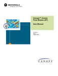
Canopy™ Access Point Cluster
and Gen I Cluster Management
Module
USER MANUAL
APCMM102-UM-E
R 03 01
© 2002 Motorola, Inc. All rights reserved. Printed in the U.S.A.
NOTICES
Federal Communication Commision (FCC) and Industry Canada (IC) Notification:
This device complies with part 15 of the FCC Rules and Regulations and RSS-210 of Industry
Canada. Operation is subject to the following two conditions: (1) This device may not cause
harmful interference, and (2) This device must accept any interference received, including
interference that may cause undesired operation. In Canada, users should be cautioned to take
note that high power radars are allocated as primary users (meaning they have priority) of 5250 –
5350 MHz and 5650 – 5850 MHz and these radars could cause interference and/or damage to
license-exempt local area networks (LELAN).
This equipment has been tested and found to comply with the limits for a Class B digital device,
pursuant to Part 15 of the FCC Rules and RSS-210 of Industry Canada. These limits are designed
to provide reasonable protection against harmful interference in a residential installation. This
equipment generates, uses, and can radiate radio-frequency energy and, if not installed and used
in accordance with these instructions, may cause harmful interference to radio communications.
If this equipment does cause harmful interference to radio or television reception, which can be
determined by turning the equipment on and off, the user is encouraged to correct the interference
by one or more of the following measures:
• Increase the separation between the affected equipment and the unit;
• Connect the affected equipment to a power outlet on a different circuit from that which the
receiver is connected to;
• Consult the dealer and/or experienced radio/TV technician for help.
FCC ID: ABZ89FC3789
FCC ID: ABZ89FC4816
IC: 109W-5200
IC: 109W-5700
The term “IC:” before the radio certification number only signifies that Industry Canada
technical specifications were met.
Important Note:
Intentional or unintentional changes or modifications must not be made unless under the express
consent of the party responsible for compliance. Any such modifications could void the user’s
authority to operate the equipment and will void the manufacturer’s warranty. The Canopy
Subscriber Module (SM) must be installed to provide a separation distance of at least 20 cm (7.9
in) from all persons, when adding the Canopy reflector dish (in the 5.7 GHz band), the reflector dish
must be installed to provide a separation distance of at least 1.5m (59.1 in) from all persons and
does not emit a RF field in excess of Health Canada limits for the general population; consult
Safety Code 6, obtainable from Health Canada’s website http://www.hc-sc.gc.ca/rpb. Furthermore,
it must not be co-located or operating in conjunction with any other antenna or transmitter.
MOTOROLA, the stylized M Logo and all other trademarks indicated as such herein are
trademarks of Motorola, Inc. ® Reg. U.S. Pat & Tm. Office. Canopy is a trademark of Motorola,
Inc. All other product or service names are the property of their respective owners.
Motorola, Inc
Broadband Wireless Technology Center
50 East Commerce Drive
Schaumburg, IL 60173
http://www.motorola.com/canopy
Page 2
TABLE OF CONTENTS
GETTING STARTED ..............................................................................................5
Welcome......................................................................................................................................... 5
Intended Use .................................................................................................................................. 5
Warranty ......................................................................................................................................... 5
PRODUCT DESCRIPTION .....................................................................................6
Operation ........................................................................................................................................ 6
Configuration .................................................................................................................................. 6
BACKGROUND INFORMATION on NETWORKING.............................................9
SYSTEM OVERVIEW AND SITE PLANNING ......................................................10
Site Selection Criteria ................................................................................................................... 11
General Considerations................................................................................................................ 12
Channel Plans .............................................................................................................................. 13
5.2 GHz Recommended Frequencies....................................................................................... 13
5.7 GHz Recommended Frequencies....................................................................................... 13
Single Access Point Module ..................................................................................................... 13
Single Access Point Cluster...................................................................................................... 13
Multiple Access Points Clusters................................................................................................ 14
Networking Information................................................................................................................. 15
Lightning Protection ...................................................................................................................... 15
Electrical Requirements................................................................................................................ 15
ADVANCED FEATURES......................................................................................16
DES Encryption ............................................................................................................................ 16
Bandwidth Capping....................................................................................................................... 16
High Priority Bandwith .................................................................................................................. 16
Branding ....................................................................................................................................... 17
SNMP ........................................................................................................................................... 18
INSTALLATION ....................................................................................................19
Unpack the Canopy Products....................................................................................................... 19
Configuration of the Access Point Modules.................................................................................. 19
Configuration of the Cluster Management Module....................................................................... 20
Installation of the Equipment ........................................................................................................ 20
Verification .................................................................................................................................... 22
CABLING..............................................................................................................23
THE INTERFACE SCREENS ...............................................................................25
Quick Start .................................................................................................................................... 25
Status Page .................................................................................................................................. 26
Configuration ................................................................................................................................ 28
Event Log...................................................................................................................................... 33
LUID Select................................................................................................................................... 33
Link Test ....................................................................................................................................... 34
Time & Date.................................................................................................................................. 34
Page 3
Sessions ....................................................................................................................................... 35
GPS Status ................................................................................................................................... 37
Ethernet Stats ............................................................................................................................... 37
Expanded Stats ............................................................................................................................ 38
ACCESSORIES ....................................................................................................39
APPENDIX............................................................................................................40
SPECIFICATIONS ................................................................................................41
Access Point Module .................................................................................................................... 41
Cluster Management Module Gen I.............................................................................................. 42
Environmental............................................................................................................................... 42
AC Power...................................................................................................................................... 42
DC Power (24V)............................................................................................................................ 42
DC Power (12V)............................................................................................................................ 42
Cable Specifications ..................................................................................................................... 42
Page 4
GETTING STARTED
WELCOME
Thank you for your purchase of a Motorola Canopy access point cluster and/or cluster
management module. This new technology is the latest innovation in high speed wireless
networking. Some of the Canopy system features are:
-
Network speeds of 10/100 BaseT
Small compact design
No special set up on your PC.
INTENDED USE
This manual is intended to be used with Canopy software release version 3.x or greater. The
intended audience for this manual is system operators and equipment installers.
WARRANTY
Motorola offers a warranty covering a period of 90 days from the date of purchase by the customer.
If a product is found defective during the warranty period, Motorola will repair or replace the product
with the same or a similar model, which may be a reconditioned unit, without charge for parts or
labor.
IN NO EVENT SHALL MOTOROLA BE LIABLE TO YOU OR ANY OTHER PARTY FOR ANY
DIRECT, INDIRECT, GENERAL, SPECIAL, INCIDENTAL, CONSEQUENTIAL, EXEMPLARY OR
OTHER DAMAGE ARISING OUT OF THE USE OR INABILITY TO USE THE PRODUCT
(INCLUDING, WITHOUT LIMITATION, DAMAGES FOR LOSS OF BUSINESS PROFITS,
BUSINESS INTERRUPTION, LOSS OF BUSINESS INFORMATION OR ANY OTHER
PECUNIARY LOSS, OR FROM ANY BREACH OF WARRANTY, EVEN IF MOTOROLA HAS
BEEN ADVISED OF THE POSSIBILITY OF SUCH DAMAGES. (Some states do not allow the
exclusion or limitation of incidental or consequential damages, so the above exclusion or limitation
may not apply to you.) IN NO CASE SHALL MOTOROLA’S LIABILITY EXCEED THE AMOUNT
YOU PAID FOR THE PRODUCT.
Page 5
PRODUCT DESCRIPTION
OPERATION
The Canopy access point modules’ simple design allows for deployment ease. The Canopy cluster
management module provides everything necessary to make a system of single or multiple Canopy
access point modules operational. It provides power, GPS synchronization and Ethernet
connectivity.
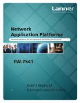
CONFIGURATION
Access Point Module
As shown below, the base cover of the module snaps off to expose the Ethernet and GPS sync
connectors as well as diagnostic LEDs. The base cover is released by depressing a lever on the
back side of the base cover.
Canopy AP
RJ45
Connector
RJ11
Connector
Connection
LEDs
Base Cover
Base Cover
Release
Lever
Ethernet
Cable
Base Cover
Ethernet
Cable
The diagnostic LEDs report information about the current status of the access point module. The
following descriptions explain the function of each LED from left to right.
LNK: The link LED displays the status of the Ethernet link to the Canopy module. The LED will be
constantly lit if there is an Ethernet link present. The LED is colored green.
ACT/4: The activity LED displays the status of any data activity on the Ethernet link. The LED will
flash (at no particular speed) when data is being transferred on the Ethernet link. The LED is
colored orange.
GPS/3: The GPS LED displays the status of the sync pulse and is lit constantly when the pulse is
being received. The LED is red.
SES/2: The session LED is not used on the access point module. The LED is green.
Page 6
SYN/1: The sync LED displays sync status. In short, this LED will lit all the time on an access
point module. The LED is orange.
PWR: The power LED displays the status of power to the module. The LED will be constantly lit if
power is applied correctly. The LED is red.
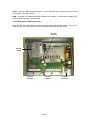
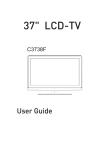
Cluster Management Module generation I
There are four major assemblies contained inside the cluster management module. They are the
Ethernet switch, the power transformer, the interconnect board and the GPS receiver.
DC power
connectors
Ethernet
Switch
GPS Sync
connectors
Ethernet
connectors
Page 7
AC power
connectors
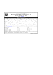
There are three openings on the bottom of the cluster management module as shown in the figure.
GPS Sync cable
opening
N-connector
Ethernet cable
opening
Page 8
Power cable
opening
BACKGROUND INFORMATION ON NETWORKING
Computers are assigned IP addresses by network operators, which have two methods available,
static or dynamic IP addressing. The user of this document will need to understand how IP
addressing is done at their particular location.
All Canopy radio products (Subscriber Modules, Access Point Modules, and Backhaul Modules)
have the default IP address of 169.254.1.1. For a computer to talk to Canopy, as it comes from the
factory, either of the following conditions must be met:
•
•
If the computer is not configured for DHCP, then it has to have a static IP address on the
169.254 network (i.e. 169.254.1.5)
If the computer is configured for DHCP, then it will automatically obtain an IP address on
the 169.254 network after minute or two as long as it is not connected to the network.
Page 9
SYSTEM OVERVIEW AND SITE PLANNING
Definitions:
Access Point Module – one (1) module that is used to distribute Internet services in a 60-degree
sector of up to 200 subscribers.
Access Point Cluster – two (2) to six (6) access point modules used to distribute Internet service to
a community of up to 1200 subscribers. Each access point module will cover a 60-degree sector
for a total of up to 360 degrees.
Cluster Management Module – a module that contains power, GPS timing, and networking for an
access point cluster. Canopy backhaul modules can also be connected to the cluster management
module making it the central connectivity point for an entire site.
Overview:
In the Canopy System, each subscriber module communicates with an access point module in an
assign time slot that is controlled by the access point. The access point module coordinates the
data needs of the subscriber in both the downlink and the uplink to allow for seamless
communication throughout the entire network.
Access point modules utilize a multipoint protocol to communication with each of the subscriber
modules registered in the system. Access point modules can be deployed in either the 5.2 GHz
band or the 5.7 GHz band allowing for a very versatile system architecture to reach out through the
last-mile to all potential customers.
In the 5.2 GHz band, subscriber module may be as far as 2 miles away from the access point
module. In the 5.7 GHz band, subscriber module may be as far as 10 miles away from the access
point module when utilizing a Canopy passive reflector kit on the subscriber. Note: Distances may
vary based on terrain and other line of sight issues.
To bring a network feed out to a remotely located access point cluster the Canopy backhaul
module can be utilized to create a point-to-point link out to the location. The Canopy backhaul
module will interface with the cluster management module to seamlessly integrate the entire
system. For more information on the Canopy Backhaul Module see its user manual.
The cluster management module is key to the operation of the Canopy System. At one cluster site
or throughout the system the cluster management module provides a GPS timing pulse to each
module so that their transmission cycles are synchronized. If one access point module were to not
be synchronized then it may be transmitting during a receive cycle of the other modules and cause
the receiver to be desensitized. This is also true of the Canopy backhaul timing master modules.
Page 10
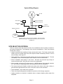
System Wiring Diagram
AP units
GPS sync & Ethernet
cables from each unit*
GPS antenna
GPS antenna
cable
Network Connection
in
optional
backhaul module
300SS
AP Installation Kit
AC or DC
power in
grounding
system
* Cables from only 1 sector are shown in diagram. There are 2 cables,
Ethernet and GPS sync, that would connect each sector unit to the AP
Installation kit.
SITE SELECTION CRITERIA
There are various issues that need to be taken into consideration when choosing a location for
the network infrastructure. The following is a list of those considerations. There may be others
as each site is unique.
• Height is essential when installing a Canopy access point cluster. The Canopy access point
cluster must be mounted higher than other objects located immediately around it such as
trees, buildings, tower legs, etc.
• There should be no obstructions that will interfere with the unit’s internal antenna. The area
immediately in front of an access point module must be clear of all obstructions.
• Will the installation area change in the future? Will there be structures high enough to
interfere with the signal? Will trees grow into the line-of-sight path?
• When possible, avoid high RF energy sites (i.e. AM/FM stations, high powered antennas,
etc.) Do not place Canopy equipment in the same plane as other RF equipment.
• The means used by the installer to attach the access point cluster to the tower, rooftop, or
pole should be rigid and should not move or flex due to wind or other vibrations.
• Tower availability…will a tower have to erected?
• There must be grounding systems available for protection of the Canopy equipment.
• Lighting arrestors are required in installation area to transport lightning strikes away from
equipment.
Page 11
GENERAL CONSIDERATIONS
•
Fresnel Loss - The Fresnel Zone is a theoretical area around the line of sight of an antenna
transmission that can affect the signal strength. Objects that penetrate the Fresnel Zone can
cause fading of the transmitted signal. This fading is caused by the cancellation of the signal
due to out-of-phase reflections. An unobstructed line of sight is important, but it is not the
only determination of an adequate placement. Even though the path has a clear line of
sight, if obstructions (such as terrain, vegetation, metal roofs, cars, etc.) penetrate the
Fresnel zone, there may be signal loss. The following illustrates a Fresnel zone.
Fresnel Zone
D1
D2
Transmitter
Receiver
•
Free Space Path Loss – As an RF signal travels through space, it is attenuated by the
distance from the initial transmission point. The farther away from the transmission point,
the weaker the RF signal.
•
Foliage Loss – Tree and plant foliage will cause additional signal loss. Seasonal density,
moisture content of the foliage, and other factors such as wind may change the amount of
loss. Caution should be used when a link may transmit though this type of environment.
•
Carrier to Interference – describes how much signal advantage must be engineered into
the radio link to tolerate an interfering transmission.
•
How many access point clusters are being planned for deployment? Each cluster will need
to utilize a cluster management module for seamless operation within the entire Canopy
System.
•
How many access point modules are being planned for each site in the deployment?
Access point modules can be distributed; they do not necessarily have to be mounted
immediately next to each other for operation. For example, if the site is a three-legged
tower, two access point modules can be mounted to each of the tower legs.
•
How will the subscriber modules be deployed relative to planned access point clusters?
Page 12
CHANNEL PLANS
Whether utilizing 5.2 GHz or 5.7 GHz modules, frequencies should never be placed
closer than 20 MHz. The Canopy modules allow the operator to chose frequencies every
5 MHz. This is so that in the event of co-location with other equipment the operator can
customize the channel layout for interoperability.
5.2 GHz Recommended Frequencies
The following are the 3 non-overlapping channels that are recommended by the Canopy team for
use with an access point cluster:
•
5.275 GHz
•
5.300 GHz
•
5.325 GHz
5.7 GHz Recommended Frequencies
The following are the 4 non-overlapping channels that are recommended by the Canopy team for
use with an access point cluster Note: only 3 channels are actually needed for the fully populated
cluster. The four channels are also used for backhaul point-to-point links:
•
5.745 GHz
•
5.765 GHz
•
5.785 GHz
•
5.805 GHz
Single Access Point Module
A single access point module can utilize any of the frequency channels that are available.
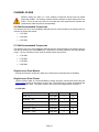
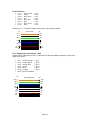
Single Access Point Cluster
Use the following table as a recommendation to assign frequency channels and sector IDs (see
Configuration section for information on sector IDs. Each frequency is reused on the sector that
is at a 180-degree offset. The symbol refers to the layout in the diagram below (FIGURE 1).
5.2 GHz Plan
Direction of Access Point sector
0
North – (0 )
Frequency
Sector ID
Symbol
5.275 GHz
0
A
5.300 GHz
1
B
Southeast – (120 )
5.325 GHz
2
C
South – (1800)
0
Northeast – (60 )
0
5.275 GHz
3
A
0
Southwest – (240 )
5.300 GHz
4
B
Northwest – (3000)
5.325 GHz
5
C
Page 13
5.7 GHz Plan
Direction of Access Point sector
Frequency
North – (00)
5.745 GHz
0
A
5.765 GHz
1
B
5.785 GHz
2
C
0
Northeast – (60 )
0
Southeast – (120 )
0
South – (180 )
Sector ID
Symbol
5.745 GHz
3
A
0
Southwest – (240 )
5.765 GHz
4
B
Northwest – (3000)
5.785 GHz
5
C
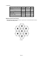
Multiple Access Points Clusters
When deploying multiple access point cluster in a given area it is recommended that the clusters
be aligned in the following manner.
A
C
A
B
B
B
A
B
C
A
A
B
A
B
C
A
C
A
C
C
A
FIGURE 1
Page 14
B
B
B
B
C
A
C
B
B
B
B
C
A
C
C
A
A
C
C
C
A
NETWORKING INFORMATION
The Canopy access point module will each utilize an IP address on the operator’s network. It is
recommended that the access point modules never be placed directly onto the Internet. IP
addresses may be assigned sequentially clockwise around an access point cluster for easier
manageability. The operator will also need to identify the appropriate subnet mask and network
gateway each of the modules.
From the factory, each access point module is assigned a unique MAC address and the following
default networking information:
•
IP address of 169.254.1.1
•
Subnet mask of 255.255.0.0
•
Network gateway of 169.254.0.0
LIGHTNING PROTECTION
• The Canopy access point module, cluster management module, and GPS antenna must
be mounted at least 2 feet below the highest point at the site for lightning strike mitigation.
It is highly recommended that the site have a lightning protection system installed.
• Ensure the location is properly grounded for lightning protection according to all applicable
national and local codes.
• To protect operator equipment from surges on the Ethernet cable that is connected to the
Canopy System, the Canopy surge suppressor must be used.
ELECTRICAL REQUIREMENTS
•
Specifications for the voltages and distance can be found in the Specification section of
this manual.
•
Make certain the installation conforms to the National Electrical Code (NEC), country and
local codes.
If uncertain of code requirements, obtain the services of a licensed
electrician.
Page 15
ADVANCED FEATURES
These features may be utilized in the Canopy System but are not required for basic operation.
DES ENCRYPTION
DES (Data Encryption Standard) is a secret key encryption scheme. The basics of DES are that it
performs a series of bit permutations, substitutions, and recombination operations on blocks of data
utilizing a secret key. On the Canopy system, DES encryption of the over the air link is done on a
per access point module or backhaul timing master module basis and does not affect the
performance or throughput of the system. The Canopy modules contain unique factory
programmed secret keys to establish the encrypted link.
BANDWIDTH CAPPING
Bandwidth capping is done on a per access point module basis. All subscriber modules that
register to an access point module will receive the same bandwidth cap information. The tokenbucket schema that is used for bandwidth capping consists of a “bucket” who’s volume defines the
burst rate and is “filled with tokens” at a rate defined by the data rate. When user data is controlled
by Canopy bandwidth capping, traffic is only passed if enough tokens exist within the bucket. As
traffic is passed, each packet uses some of the tokens.
For example, imagine an access point module is configured for a 256 Kbps continuous rate with a
10 Mbit burst to each of the registered subscriber modules. A 10 Mbit token bucket is created for a
subscriber. This bucket will be filled with tokens at the rate of 256 Kbps. If no transmissions were
to occur, then the bucket will continue to fill at the rate until it reaches its 10 Mbit token capacity.
When user traffic is identified, a check is made to see if that many tokens exist in the bucket. If
there are enough, then the tokens are removed that the user data is sent on its way. If there are
not enough tokens, the the user data is discarded.
To the user, the schema has two intended effects:
• Traffic that requires data streams of less than 10 Mbits in size are delivered at the
maximum supported rate by the air interface.
• Large downloads (such as a Windows update or MPEG file) are limited to 256 Kbps after
their initial burst runs out.
HIGH PRIORITY BANDWITH
To support traffic with a low latency requirement such as VoIP (voice over IP), the Canopy System
implements a high priority data pipe. This implementation does not affect the inherent latencies in
the Canopy System but allows high priority traffic to be serviced immediately. The high priority pipe
separates low latency trafiic from traffic that is latency tolerant such as standard web surfing and
file downloads. This traffics is separated by the Canopy System via the IPv4 TOS (type of service)
Low Latency bit. If this bit is set, the packet will be sent on the high priority pipe. This pipe is
serviced before any normal priority traffic.
The high priority system is enabled via four fields found in the Configuration web page. The fields
are:
• High Priority Uplink Percentage
• Uacks Reserved High
• Dacks Reserved High
• NumCtrlSlots Reserved High
The High Priority Uplink Percentage parameter describes the percentage of the uplink bandwidth
that will be dedicated to low latency traffic. When set, this percentage of RF link bandwidth will be
permanently allocated to low latency traffic regardless of the amount of this kind of traffic present.
Page 16
There is no corresponding downlink parameter as this bandwidth is allocated on as-needed basis
by the scheduling algorithms.
The UAcks (Uplink ACK) Reserved High parameter describes the number of slots used to
acknowledge high priority data that is received by a subscriber module. The Canopy team
recommends that this parameter be set to 3 and then the TotalNumUAcksSlots parameter should
be set to 6.
The DAcks (Downlink ACK) Reserved High parameter describes the number of slots used to
acknowledge high priority data that is received by an access point module. The Canopy team
recommends that this parameter be set to 3 and NumDAckSlots parameter should be set to 6.
The NumCtrlSlots Reserved High parameter describes the number of slots used to send control
messages to an access point module. The Canopy team recommends that this parameter be set
to 3 and the NumCtlSlots parameter should be set to 6.
When all these parameters are configured, all high priority traffic in the uplink direction will be
serviced via this pipe at the percentage configured. This is true even if the high priority traffic
volume exceeds the configured capacity and there is no non-high priority traffic.
BRANDING
On each Canopy module, the web-based interface screens have a Canopy logo that can be
replaced with an operator’s company logo. The Canopy logo file is called canopy.jpg and the
replacement file must also be called canopy.jpg. The new file is transferred via FTP to the module
and then added to a special filesystem through a telnet session. The following command can be
used during a telnet session:
• addwebfile – add a custom logo file to the filesystem
• clearwebfile – clear the customer logo file from the filesystem
• lsweb – list the custom logo file and display the storage space available on the filesystem
The following is a sample FTP session:
> ftp 169.254.1.1
Connected to 169.254.1.1
220 FTP server ready
Name (169.254.1.1:none): root
331 Guest login ok
Password: <password-if-configured>
230 Guest login ok, access restrictions apply.
ftp> binary
200 Type set to I
ftp> put canopy.jpg
ftp> quit
221 Goodbye
The following is a sample telnet session:
/---------\
C A N O P Y
Motorola Broadband Wireless Technology Center
(Copyright 2001, 2002 Motorola Inc.)
Login: root
Password: <password-if-configured>
Telnet+> lsweb
Flash Web files
free directory entries: 32
free file space
64336 bytes
Page 17
Telnet+> addwebfile canopy.jpg
Telnet +> lsweb
Flash Web files
/canopy.jpg
7867
free directory entries: 31
free file space: 56468
Telnet +> clearwebfile
Telnet+> lsweb
Flash Web files
free directory entries: 32
free file space
64336 bytes
SNMP
Simple Network Management Protocol (SNMP) can be utilized to monitor the Canopy modules.
The standard MIB-II (systems and interfaces) objects are programmed into the modules. For
specific information on this MIB see RFC 1213 for details.
Page 18
INSTALLATION
The following steps are required to install the Canopy access point module(s), the cluster
management module, and the GPS antenna:
•
Unpack the Canopy products
•
Configuration of the access point modules
•
Configuration of the cluster management module
•
Installation of the access point modules, cluster management module, and GPS antenna
•
Verification
UNPACK THE CANOPY PRODUCTS
Upon receipt, carefully inspect all shipping boxes for signs of damage. If there is damage,
immediately notify the transporatation company.
Unpack equipment, making sure that all ordered components have arrived. It is recommended that
you save all the packing materials. They can be used for transportation of the equipment to and
from installation sites.
CONFIGURATION OF THE ACCESS POINT MODULES
In all cases, when a configuration parameter is modified, the change must be saved and
the module must be rebooted.
The are two methods that can be utilized to configure each of the access point modules. The first
method is to utilize the Quick Start feature of the product. For more information on Quick Start see
The Interface Screens. The second is to manually set each of the parameters.
The access point module, from the factory, is configured to not transmit on any frequency. This is
done so that an operator does not accidentally turn on an unsynchronized access point module.
An operator will need to verify the following information:
•
Will the access point module need to generate its own sync pulse or will it receive it from
the cluster management module?
•
The operator will assign a RF frequency for the module to transmit.
•
The operator may assign value for uplink and downlink bandwidth capping. If the access
point module is in a cluster with other modules then this parameters on all units must be
set exactly the same.
•
The operator will assign an IP address to the module for the network it will be installed on
and assign an appropriate subnet mask and network gateway.
•
The operator must configure the appropriate color code on the access point module so that
subscriber modules can register with it. The color codes must match for registration.
•
The operator must configure the maximum range that the access point module will register
a subscriber module. If the access point module is in a cluster with other modules then this
parameter on all units must be set exactly the same.
•
The operator can prevent unauthorized users from connectig to the access point module’s
web based interface by assigning a password. There is no default password and
password protection is turn off is turn off from the factory.
Page 19
Passwords can be from 1 to 16 characters. Any combination of characters is allowed,
except for these special characters: “ , . ‘ { } / \ ; : [ ] ( ) ` ~
NOTE: If the operator forgets either the password or the IP address for the module, a
Canopy default plug can be used to regain access. See Configuration section for detail on
default plug.
There are two types of passwords that can be configured: display-only or full-access. The
display-only password allows the operator to view the module’s current status. The fullaccess password allows the operator to view the module’s current status and change its
configuration. By viewing the red lettering to the right of the entry fields, the operator can
discern that a password is set.
•
The operator can enter in information about the Site Name, Location, and Contact. This is
optional.
CONFIGURATION OF THE CLUSTER MANAGEMENT MODULE
The operator will need to verify the following when configuring a cluster management module:
•
What type of power will the module utilize, AC or DC?
•
If utilizing AC power, connect to the AC power connectors.
•
If utilizing DC power, disconnect the power transformer from the DC power connectors and
connect DC power lines.
INSTALLATION OF THE EQUIPMENT
The following tools may be needed during installation:
• 3/8” nut driver
• 12” adjustable wrench
• 7/16” wrench for installation of GPS mounting bracket
• Needle-nose pliers
• Utility knife
When power is applied to a Canopy module or the unit reset via the web-based interface, the
module will take approximately 25 seconds to boot up. During this boot up time, power on selftests and other diagnostics are being performed.
The following steps are needed to install the Canopy equipment:
• Remove the base cover from all Canopy access point modules to be installed.
• Remove the GPS sync cable knockout from the base cover with needle-nose pliers.
• Mount the access point modules:
o
•
The modules can be mounted in a variety of locations, choose the best location
for your particular application. Mounting can be done by utilizing stainless steel
hose clamps or another equivalent fastener.
Mount the cluster management module
o
Mount the module in a location that will allow access for service if necessary.
The farthest that the access point modules can be is 100 feet (30.5 meters).
Page 20
o
o
The module should not be mounted closer than 6 feet to the access point modules
or backhaul modules
• Mount the GPS antenna
o
The GPS antenna must be located so that it has an unobstructed view of the sky
(20-degrees off the horizon) and is not the highest item at the installation site.
o
The GPS antenna mount is provided with U-bolts for pole sizes of 1.25 – 1.50
inches (31.8 – 38.1 mm).
• Route the Ethernet cables from the access point modules to the cluster management module.
The strain relief plugs need to be cut to slip cables in.
o
The Ethernet cables use RJ-45 connectors (standard Ethernet) that connect to
matching ports within the cluster management module.
Always connect
modules starting at port 1. This port is the master port for the CMM.
o
A total of 8 ports are available on the cluster management module, to
accommodate a combination of access point modules and potentially backhaul
modules.
o
Connect the remaining Ethernet cables in the same manner.
• Route the GPS sync (serial) cables from the access point modules to the cluster
management module.
o
The GPS sync cables use 6 conductor RJ-11 connectors that connect to matching
ports within the cluster management module. Always connect modules starting
with port 1. This port is the master port for the CMM.
o
Connect the remaining GPS sync cables in the same manner.
• If necessary, route a network cable into the cluster management module and connect to the
uplink port on the switch. As with any such installed devices, proper grounding of the
Ethernet cable is necessary. The Canopy Surge Suppressor is such a device for this
situation.
• Connect GPS coax cable to N-connector on the outside of the cluster management module.
Page 21
• Connect AC or DC power to the cluster management module.
• When power is applied the “power” LED on the Ethernet switch should come on.
• Verify that all of the access point modules are reliably connected to the Ethernet switch by
observing that each port indicator LED on the Ethernet switch are lit.
• Replace the base cover on all of the access point modules.
• Close and lock the cluster management module.
All Canopy modules connected to the cluster management module must be configured to
“Sync to Received Signal”. Otherwise GPS timing pulse will not be transmitted to the
modules.
VERIFICATION
•
Access the web based interface for each access point module by opening up http://<ipaddress> where the <ip-address> is the address of the individual module.
•
Click on “GPS Status” from the menu located on the left hand side of the web page.
•
Verify that the access point module is seeing and tracking satellites. The module must be
tracking at least 4 satellites for the timing pulse to be generated.
•
Take a subscriber module into the area surrounding the newly installed access point
cluster and verify that the subscriber module registers to each of the installed access point
modules. The subscriber must have the same color code as the access point for
successful registration (assuming that there is also a clear line-of-sight).
•
When the subscriber module is registered, verify the following:
o
Frequency of the access point module registered to
o
Sector ID of the access point module registered to
o
Physical position of the Access Point Module registered to
If the information that is reported back does not conform to your initial deployment plan, reconfigure
the access point cluster to bring it into compliance.
Page 22
CABLING
The following information describes the wiring standards for installing a Canopy system. All
diagrams utilize the EIA/TIA 568B color standard.
•
•
•
When connecting a Canopy device directly to a network interface card (NIC)
utilize a RJ-45 straight-thru cable.
When connecting a Canopy device directly to a hub, switch, or router utilize a
RJ-45 crossover cable.
The maximum cable run with the AC wall adapter is 328 feet (100 meters).
When utilizing the Canopy AC wall adapter the +V is +11.5VDC to +30VDC with a nominal value of
+24 VDC.
RJ-45 Straight-Thru:
pin 1 →
pin 2 →
pin 3 →
pin 4 →
pin 5 →
pin 6 →
pin 7 →
pin 8 →
white / orange
orange
white / green
blue
white / blue
green
white / brown
brown
← pin 1
← pin 2
← pin 3
← pin 4
← pin 5
← pin 6
← pin 7
← pin 8
Where pins 4, 5, 7, and 8 are used to carry power to the Canopy modules.
Pin
RJ-45 Straight-Thru
Pin
TX+ 1
1 RX+
TX- 2
2 RX-
RX+ 3
3 TX+
+V
4
4
5
5
RX- 6
+V
return
+V
6 TX-
7
7
8
8
+V
return
Page 23
RJ-45 Crossover:
pin 1 →
pin 2 →
pin 3 →
pin 4 →
pin 5 →
pin 6 →
pin 7 →
pin 8 →
white / orange
orange
white / green
blue
white / blue
green
white / brown
brown
← pin 3
← pin 6
← pin 1
← pin 4
← pin 5
← pin 2
← pin 7
← pin 8
Where pins 4, 5, 7, and 8 are used to carry power to the Canopy modules.
Pin
RJ-45 Crossover
Pin
TX+ 1
3 RX+
TX- 2
6 RX-
RX+ 3
1 TX+
+V
4
4
5
5
2 TX-
RX- 6
+V
return
+V
7
7
8
8
+V
return
RJ-11 Straight-Thru (for GPS sync cable)
Utilizing CAT 5 cable and 6-pin RJ-11 connectors, the following diagram shows the wiring of the
cable for GPS sync.
pin 1 → white / orange
pin 2 → white / green
pin 3 → white / blue
pin 4 → green
pin 5 → blue
pin 6 → orange
the 4th pair is not utilized
Pin
1-pps 1
← pin 1
← pin 2
← pin 3
← pin 4
← pin 5
← pin 6
RJ-11 Straight-Thru
Pin
1 1-pps
TX+ 2
2 RX+
RX+ 3
3 TX+
not
used
4
4
5
5
not
used
gnd 6
6 gnd
not
used
not
used
Page 24
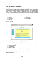
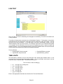
THE INTERFACE SCREENS
The Canopy access point module contains a series of web pages that are used to interface to the
unit. The following is a quick reference to interface screens. Note: These screens are subject to
change by subsequent software versions. To access the web based interface you first must be on
a computer that is in some way connected to the access point module. This can be done either
directly or through a network. Enter the IP address of the access point module (default is
169.254.1.1) into the address bar of your browser and hit enter on your keyboard. The following
web based interface pages are accessible:
•
•
•
•
•
•
•
•
•
•
•
Quick Start
Status
Configuration
Event Log
LUID Select
Link Test
Time & Date
Sessions
GPS Status
Ethernet Stats
Extended Stats
QUICK START
The Canopy System consists of a family of highly flexible, fixed wireless access devices that can
be put into service quickly and with a minimal configuration. The Quick Start is a wizard that walks
the operator through that configuration. To place an access point module into operation, only three
parameters need to be configured:
•
•
•
RF Carrier Frequency
Synchronization
Network IP Address
Each of the pages in the Quick Start will explain a little about Canopy and ask the operator for a
choice that best addresses the network requirements. At the end, the operator will be given the
opportunity to review the configuration selected and save it to non-volatile memory. None of the
changes made prior to saving the configuration will affect the system so experimentation with the
interface is encouraged.
Page 25
STATUS PAGE
The Status page contains information on the operation of the product. It is the default web page.
The following parameters are displayed:
Device Type: displays the type of Canopy module that is currently being viewed. This field will let
the operator know the frequency band of the module, the protocol that it is utilizing, and the MAC
address of the module. The frequency band can either be in the 5.2 GHz or 5.7 GHz band.
Software Version: displays the version of the software that is currently loaded into the module.
Please make note of this information when obtaining technical support.
FPGA Version: displays the version of the FPGA (field programmable gate array) that is currently
loaded into the module. Please make not of this information when obtaining technical support.
Uptime: displays the length of time the module has been operating since power was applied.
System Time: displays the current time. If the access point module is connected to a Cluster
Management Module (CMM) then the time will be Greenwich Mean Time (GMT). Any subscriber
module that registers to the access point module will inherit the system time.
Ethernet Interface: displays the configuration of the Ethernet interface on the module.
Registered SM Count: displays the number of subscriber modules currently registered to the
access point module.
GPS Sync Pulse Status: displays the current status of the type of synchronization the access
point module is receiving. There are 3 values that could be displayed:
• Generating sync: If the module is set to generate its own sync pulse then this message will
be displayed.
• Receiving Sync: If the module is set to receive a sync pulse from an outside source (not
itself) and is actually receiving the pulse then this message will be displayed.
• ERROR: No Sync Pulse: If the module is set to receive a sync pulse from an outside
source (not itself) and it is currently not receiving the pulse this message will be displayed.
Page 26
When this message is displayed the access point module will turn its transmitter off so as
to not create any self-interference within the Canopy System.
Radio Slicing Value: displays information to be used be Canopy technical support.
Radio Transmit Gain Setting: displays information to be used by Canopy technical support.
Site Name: displays information relating to the name of the physical module. This parameter can
be set by the operator on the Configuration web page. This information is set into the sysName
SNMP MIB-II object and can be polled via a SNMP management server.
Site Contact: displays contact information for the physical module. This parameter can be set by
the operator on the Configuration web page. This information is set into the sysContact SNMP MIBII object and can be polled via a SNMP management server.
Page 27
CONFIGURATION
The Configuration web page contains information and configurable parameters pertaining to the
operation of the product. The first line of information on the Configuration screen is a repeat of the
Device Type from the Status web page. The following are the parameters and their descriptions.
Sync Input: choose the type of synchronization that this access point module will utilize. If “Sync
to Received Signal” is chosen, then it is assumed that:
• this access point module it connected to a Cluster Management Module and will be
receiving a sync pulse via GPS
• this access point module is connected to another access point module that is generating its
own sync pulse.
If “Generate Sync Signal” is chosen then it is assumed that:
• this access point module is a stand-alone module with no other access point modules
within a 5 mile radius.
• this access point module is generating the sync pulse for a cluster of access point modules
and there are no other access point modules within a 5 mile radius.
Link Negotiation Speeds: choose the type of link speed desired for the Ethernet connection. The
default for this parameter is for all the choices to be checked.
RF Frequency Carrier: choose the frequency that the module will transmit on. The default from
the factory is to have this parameter set to none.
Downlink Data: choose the percentage of the aggregate throughput that is needed for the
downlink (i.e going from the access point module to the subscriber). For example, if the aggregate
throughput on the access point module is 6 Mbits, then configuring this parameter for 75% will
allocate 4.5 Mbits for the downlink and 1.5 Mbits for the uplink. If the access point module is in a
cluster with other modules then this parameter on all units must be set exactly the same. The
default for this parameter is 75%.
High Priority Uplink Percentage: describes the percentage of the uplink bandwidth that will be
dedicated to low latency traffic. When set, this percentage of RF link bandwidth will be
permanently allocated to low latency traffic regardless of the amount of this kind of traffic present.
Page 28
There is no corresponding downlink parameter as this bandwidth is allocated on as-needed basis
by the scheduling algorithms.
Total NumUAckSlots: describes the total number of slots used to acknowledge data that is
received by a subscriber module. If the access point module is in a cluster with other modules then
these parameters on all units must be set exactly the same. The default should be set to 3.
Uacks Reserved High: describes the number of slots used to acknowledge high priority data that
is received by a subscriber module. The Canopy team recommends that this parameter be set to 3
and then the Total NumUAcksSlots parameter should be set to 6.
NumDAckSlots: describes the total number of slots used to acknowledge data that is received by
an access point module. If the access point module is in a cluster with other modules then these
parameters on all units must be set exactly the same. The default should be set to 3.
Dacks Reserved High: describes the number of slots used to acknowledge high priority data that
is received by an access point module. The Canopy team recommends that this parameter be set
to 3 and NumDAckSlots parameter should be set to 6.
NumCtlSlots: describes the total number of slots used to send control messages to an access
point module. If the access point module is in a cluster with other modules then these parameters
on all units must be set exactly the same. The default should be set to 3.
NumCtlSlots Reserved High: describes the number of slots used to send control messages to an
access point module. The Canopy team recommends that this parameter be set to 3 and the
NumCtlSlots parameter should be set to 6.
Sustained Uplink Data Rate: choose the rate at which all registered subscribers modules will be
capped in the uplink direction. The default is 10,000 kbps, which means that there is no restriction
on the uplink.
Uplink Burst Allocation: choose the maximum value that each individual subscriber module
would have for burst traffic in the uplink direction. The default is 10,000 kbps.
Sustained Downlink Data Rates: choose the rate at which all registered subscriber modules will
be capped in the downlink direction. The default is 10,000 kbps, which means that there is no
restriction on the downlink.
Downlink Burst Allocation: choose the maximum value that each individual subscriber module
would have for burst traffic in the downlink direction. The default is 10,000 kbps.
LAN IP: enter in the IP address that will be associated with the Ethernet connection on this
module. The default address is 169.254.1.1. If the IP address is forgotten, the operator will need
physical access to the module and will need to create a Canopy “default plug”. See steps at the
end of this section for use of a default plug.
LAN Subnet Mask: enter in an appropriate subnet mask for the module to “talk” on the network.
The default value for this parameter is 255.255.255.0
Default Gateway: enter in the appropriate gateway for the module to “talk” on the network. The
default for this parameter is 169.254.0.0
Private IP: the default for this parameter is 192.168.101.1. It is recommended that the operator
not change this parameter. A flat, class C subnet is used to communicate with each of the
subscriber modules that have registered. The access point utilizes a combination of the private IP
and the logical unit ID (LUID) of the subscriber module.
Page 29
For example, if there are two subscriber modules (LUID 2 and LUID 3) registered to an access
point module, then the access point uses the following to communicate to each:
Unit
access point module
subscriber module 1
subscriber module 2
LUID
1
2
3
Private IP
192.168.101.1
192.168.101.2
192.168.101.3
If the private IP address is changed then it must designate a Class C subnet that s not utilized for
anything else and the address must be in the form of xxx.xxx.xxx.1, where 1 is the last octet of the
address.
Color Code: enter in a value (0-254). The color code on the subscriber module and the access
point module must match in order for registration to occur. Color code is not a security feature. It
is a means for the Canopy System operator to segregate an individual network or neighbor Canopy
networks. Also, color code can be used to force a subscriber module to only register to a specific
access point module even though the subscriber module may be able to see multiple access point
modules. The default value for this parameter is 0 on all Canopy modules.
Sector ID: choose an ID number to give to this access point module. This parameter does not
affect the operation of the module in any way. Its purpose is just another means to identify the
access point module. When observing a subscriber module’s AP Eval Data web page, the sector
ID is one of the distinguishing fields present to help the operator understand what access point
module is seen. It is recommended that when constructing an access point cluster (2-6 modules)
that each sector be given a different ID and that the pattern be repeated throughout the entire
Canopy System for manageability.
Max Range: enter in a distance (in miles). This parameter controls the maximum distance that a
subscriber module will be allowed to register. The subscriber module must still meet minimum
requirements for an acceptable link in order to register. If the access point module is in a cluster
with other modules then this parameter on all units must be set exactly the same. The default for
this parameter is 2 miles.
Display-Only Access: enter the same password in both fields for verification. The display-only
password, when used, will allow only view activities to the module. When the display-only
password is set and not the full-access password, the display-only password will be tied to telnet
and FTP sessions to the module. If the full-access password is also set then it has precedence on
the telnet and FTP sessions. If the password is forgotten, the operator will need physical access to
the module and will need to create a Canopy “default plug” to override the unit. See steps at end of
section for use and creation of a default plug.
Full Access: enter the same password in both fields for verification. The full-access password,
when used, will allow view and change activities to the module. When the full-access password is
set, the password will also be tied to telnet and FTP sessions to the module. When prompted for
the password via the web-based interface, there is no username required; however when prompted
for the password via a telnet or FTP session, the user that MUST be used is “root”. If the password
is forgotten, the operator will need physical access to the module and will need to create a Canopy
“default plug” to override the unit. See steps at end of this section for use of a default plug.
Webpage Auto Update: enter time period (in seconds) desired to have the web browser refresh
the web-based interface. The default setting is 0, which will cause the web-based interface to
never refresh.
Page 30
Airlink Security: choose the type of air link security that is to be utilized on this access point
module. There are two choices:
• Normal: If utilizing this mode there is no encryption on the air link. This is the default
operation.
• DES: If utilizing this mode the air link is encrypted using single DES.
Bridge Entry Timeout: choose the appropriate bridge timeout for correct network operation with
existing network infrastructure. It is important that this parameter be set for a longer time period
than the ARP (address resolution protocol) cache timeout of the router being used to feed the
network.
Note: Failure to properly configure this may lead to temporary loss of
communication to specific end users.
AP Background BER Mode: choose to have this feature turned on or off. Bit Error Rate (BER)
mode will allow an operator another means to verify the functionality of a link. When BER mode is
turn on a bit error rate can be read on the subscriber side to determine the quality of a registered
link. If the access point module is in a cluster with other modules then this parameter on all units
must be set exactly the same. Continually, when this feature is on the aggregate available
bandwidth will decrease by ~200 Kbps.
Community String: enter a string that will allow a SNMP management server accessibility to the
SNMP information. There must not be any spaces in the community string. The default for this
parameter is “Canopy”.
Accessing Subnet: enter the network that will be allowed to access SNMP information from the
canopy module. There are two pieces of information needed:
• The network in the form of xxx.xxx.xxx.xxx
• The CIDR (Classless Interdomain Routing) prefix length in the form of /xx
An example would be 198.32.0.0/16 where /16 is a subnet mask of 255.255.0.0. An Internet
search on Classless Interdomain Routing will provide greater detail on this subject for the
inexperienced network operator. The default is to allow all networks access.
Trap Address: enter in an IP address (xxx.xxx.xxx.xxx) of an SNMP management server where
trap information can be sent. A trap is a way for the module to tell the monitoring system that
something has happened. The following are scenarios where traps would be sent:
• after a reboot of the module
• if a SNMP management server tried to access agent information and supplied the wrong
community string, wrong SNMP version number, or came from the wrong accessing
subnet.
Site Name: enter information relating to a name given to the physical module. This parameter will
set the supplied information into the sysName SNMP MIB-II object and can be polled by a SNMP
management server. The buffer size for this field is 128 characters.
Site Contact: enter contact information relating to the module. This parameter will set the
supplied information into the sysContact SNMP MIB-II object and can be polled by a SNMP
management server. The buffer size for this field is 128 characters.
Site Location: enter information relating to the physical location of the module. This parameter
will set the supplied information into the sysLocation SNMP MIB-II object and can be polled by a
SNMP management server. The buffer size for this field is 128 characters.
Save Changes: by clicking on this button, any changes that have been made on the Configuration
page will be committed to flash memory and will take effect after the next module reboot.
Page 31
Undo Save Changes: by clicking on this button, any changes that have been made and not
committed through a reboot of the module.
Set to Factory Defaults: depressing this button will change all of the configurable parameters (all
of which are contained on the Configuration page) back to their factory settings.
Reboot: depressing this button will reboot the module.
Canopy Default Plug
When inserted, the default plug brings the module up with a default configuration. This allows the
operator to regain control of a module, which may be using an IP address and/or password that
has been forgotten. The default plug will also override the passwords for access and change
control and set the LAN1 IP address back to 169.254.1.1. This does not, by itself, change any
configuration, rather, it allows the operator to attach to the module using the default configuration
so that they can read the actual non-default values and set them accordingly.
The following steps outline the creation of a default plug (this plug can also be purchase for a
nominal fee at http://www.best-tronics.com/motorola):
•
•
Obtain a RJ-11, 6-pin connector and a small length of CAT 5 cable.
Pin-out all 6-pins according the following diagram and then short (i.e. solder) together pins
4 and 6 on the other end. Remaining wires should not be connected to anything.
The following diagram shows the wiring of a default plug:
o
o
o
o
o
o
•
pin 1 → white / orange
pin 2 → white / green
pin 3 → white / blue
pin 4 → green
pin 5 → blue
pin 6 → orange
← pin 4
← pin 6
Insert “default plug” in the GPS sync port of the module and apply power to the module via
its Ethernet cable.
When the module is booted up (power applied) it will be in default mode where the IP address will
be 169.254.1.1 and the passwords will be blank. All other configurations will have been preserved.
Page 32
EVENT LOG
This page contains information that is recorded from the subscriber module for troubleshooting
purposes. Please make note of the information that is gathered here when calling for technical
support.
Clear Event Log: this button will clear the event log.
LUID SELECT
This web page makes is possible for the operator to view the web pages of registered subscriber
modules over the RF link. The operator should view the Sessions web page to determine what the
logical unit ID (LUID) is for the subscriber module in question. Enter the LUID into the supplied
field and click the “Change LUID” button to set the parameter. Click “View Current Subscriber
Modem” to then access the subscriber module.
Page 33
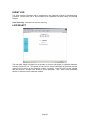
LINK TEST
The Link Test is a test for measuring the throughput and efficiency of the RF link between two
Canopy modules.
To perform a link test enter a number into the field labeled “Duration”. The duration is the number
of seconds the RF link will be tested. Start the link test by clicking the “Start Test” button. The test
will now run for the set duration. If the web page is not set to automatically refresh, click the
“Refresh Display” button to see the results. For a Canopy System link to be considered acceptable
it is necessary for the efficiencies of the link test to be greater than 90% in both the uplink and
downlink direction. It is recommended that when a new link is installed that a link test be executed
to ensure that the efficiencies are within recommended guidelines.
The key fields are:
• Downlink RATE, bits per second
• Uplink RATE, bits per second
•
•
Downlink Efficiency, percent
Uplink Efficiency, percent
TIME & DATE
This web page is utilized to set the time and date of the access point module when it is not
connected to a Cluster Management Module (CMM). The time and date would need to be set
every time there is a power cycle. The format for the entry is:
Time: hh:mm:ss Date: mm/dd/yyyy
•
•
•
•
•
•
hh:
mm:
ss:
mm:
dd:
yyyy:
two digit hour in military time
two digit minute
two digit second
two digit month
two digit day
four digit year
Enter in the appropriate information and click the Set Time and Date button.
Page 34
SESSIONS
The Session web page contains information on each of the subscriber modules that has registered
to the access point module. For each of the subscriber modules certain bits of information are
shown on this web page. An example of such information is:
LUID: 002 : MAC: 0a-00-3e-00-02-2f State: IN SESSION
Software Version : CANOPY 3.1 Aug 21 2002 13:52:12
FPGA Version : 08200207
Session Timeout: 7, AirDelay 5
Session Count: 2, Reg Count 2, Re-Reg Count 2
Average RSSI: 1842, Last RSSI: 1873
Average Jitter: 6, Last Jitter: 5
Descriptions of the parameters that are useful for managing and troubleshooting a Canopy System
are:
LUID: displays the logical unit ID of the subscriber module. As each subscriber module registers
to the access point module it is assigned a LUID. The LUID range starts at 2. If a subscriber
module were to lose its registration with the access point and then regain the registration it will
retain the same LUID, as long power has not cycled on the access point module.
MAC: displays the MAC address (or electronic serial number) of the subscriber module.
State: displays the current status of the subscriber module. There are two states:
• IN SESSION: the subscriber module is currently registered to the access point module.
• IDLE: the subscriber module was registered to the access point module at one time, but is
not currently.
Software Version: displays the version of software that is running on the subscriber module. If
this parameter is not present, then a software version prior to release version 3.1 is on that module.
FPGA Version: displays the version of FPGA that is running on the subscriber module. If this
parameter is not present, then a FPGA version prior to release version 082002 is on the module.
AirDelay: displays the distance of the subscriber module from the access point module. The
number presented needs to be multiplied by 49 to convert the number to feet.
Session Count: displays the number of sessions that this subscriber module has had with the
access point module. If this value is excessive large compared to other subscriber modules
registered with this access point, there may be an issue with the installation of the subscriber.
Reg Count: displays the number of registration request messages the access point module has
seen from the subscriber module. If this value is excessive large compared to other subscriber
modules registered with this access point, there may be an issue with the installation of the
subscriber.
Re-Reg Count: displays the number of registration request messages the access point module
has seen from the subscriber module that is already in session. If this value is excessive large
compared to other subscriber modules registered with this access point, there may be an issue
with the installation of the subscriber.
Average RSSI: displays the average RSSI value for the subscriber module.
Last RSSI: displays the last RSSI value for the subscriber module.
Page 35
Average Jitter: displays the average Jitter value for the subscriber module.
Last Jitter: displays the last Jitter value for the subscriber module.
Page 36
GPS STATUS
The GPS Status web page displays information about satellites seen and tracked when the access
point module is configured to “sync to the received signal” and is connected to a Cluster
Management Module.
ETHERNET STATS
The Packet Stats web page reports TCP throughput and error information for the Ethernet
connection of the subscriber module. The following definitions are available:
inoctets count: displays the total number of octets received on the interface, including framing
characters.
inucastpkts count: displays the total number of subnetwork-unicast packets delivered to a higher
layer protocol
innucastpkts count: displays the total number of non-unicast (i.e. subnetwork-broadcast or
subnetwork-multicast) packets delivered to a higher layer protocol.
indiscards count: displays the total number of inbound packets which were chosen to be
discarded even though no errors had been detected to prevent their be deliverable to higher layer
protocol. One possible reason to discard could be to free up buffer space.
inerrors count: displays the total number of inbound packets that contained errors preventing
them from being delivered to a higher layer protocol.
inunknownprotos count: displays the total number of packets received via the interface which
were discards because of an unknown or unsupported protocol.
outoctets count: displays the total number of octets transmitted out of the interface, including
framing characters.
outucastpkts count: displays the total number of packets that higher-level protocols requested be
transmitted to a subnetwork-unicast address, including those that were discarded or not sent.
outnucastpkts count: displays the total number of packets that higher-level protocols requested
be transmitted to a non-unicast (i.e. subnetwork-broadcast or subnetwork-multicast) address,
including those that were discarded or not sent.
outdiscards count: displays the total number of outbound packets which were chosen to be
discarded even though no errors had been detected to prevent their being transmitted. One
possible reason for discarding such a packet could be to free up buffer space.
outerrrors count: displays the total number of outbound packets that could not be transmitted
because of errors.
RxBabErr: displays the total number of receiver babble errors.
EthBusErr: displays the total number of Ethernet bus errors on the Ethernet controller.
CRCError: displays the total number of CRC errors on the Ethernet controller.
RxOverrun: displays the total number of receiver-overrun errors on the Ethernet controller.
Page 37
Late Collision: displays the total number of late collisions on the Ethernet controller. A normal
collision occurs during the first 512 bits of the frame transmission. If a collision occurs after the 512
bit times, then it is considered a late collision. A late collision should be taken as a serious network
problem, since it causes the frame being transmitted to be discarded. The most common cause of
late collisions is a mismatch between duplex configurations at each end of a link segment.
RetransLimitExp: displays the total number of retransmit limit expirations.
TxUnderrun: displays the total number of transmission-underrun errors on the Ethernet controller.
CarSenseLost: displays the total number of carrier sense lost errors occurred on the Ethernet
controller.
EXPANDED STATS
Clicking on the Expanded Stats link will display a number of pages of statistics that are maintained
by the Canopy module. Canopy Technical Support may ask the operator for specific information in
this section when troubleshooting an issue.
Page 38
ACCESSORIES
The following accessories are available for use with the Canopy System. To purchase
accessories, please contact an authorized Canopy dealer, unless otherwise noted.
•
Universal mounting bracket
•
Passive reflector dishes for use with 5.7 GHz subscriber modules.
•
90-220V AC power supply (part number ACPSSW-01)
•
Cable assemblies for the Canopy System can be ordered from Best-Tronics Manufacturing
Inc. by going to their website at HTTP://WWW.BEST-TRONICS.COM/MOTOROLA
Page 39
APPENDIX
There are two basic concepts that are needed for a basic understanding of networking, IP
addresses and subnet masks.
IP addresses are 32-bit binary numbers that have two
corresponding parts or sub-addresses, the first part identifying the network and the second part
identifying the hosts on the network. An imaginary boundary separates the first part from the
second. This imaginary boundary is marked by way of the subnet mask. The subnet mask is
another 32-bit binary number the acts like a filter on the IP address. When a subnet mask has a bit
set to 1, the corresponding bit in the IP address is part of the network address. A subnet is
classified as either a class A, class B, or class C network. The following table shows the common
subnet mask classes:
Class
Network Portion
Host Portion
A
11111111
00000000 00000000 00000000
B
11111111 11111111
00000000 00000000
C
11111111 11111111 11111111
00000000
For example, if you have an IP address of 169.254.1.1 and a subnet mask of 255.255.0.0, then the
first 16-bits of the 32-bit IP address identify the network.
10101001 11111110 00000001 00000001
11111111 11111111 00000000 00000000
IP address
Subnet Mask
There are 216 (65,536) addressable hosts in this example and 169.254 is the network. There is one
last piece of information that is needed here. Subnet masks are not shipped around in the IP
packet, the packet only contains the 32-bit IP address of the destination. So without this valuable
piece of information devices have no idea what portion of the IP address is part of the network and
which is part of the host address. How does data know where it is supposed to go? IP systems
developed a unique form of logic to make this determination. Class A network addresses always
have the first bit of their IP address set to 0. Class B network addresses always have their first bit
set to 1 and their second bit set to 0. Class C network addresses always have their first two bits
set to 1 and the third bit set to 0. By examining these first bits of the IP address a device can
determine what subnet mask should be applied to the IP address and determine where to route the
data.
The following is a synopsis of an Internet Draft (http://www.ietf.org/internet-drafts/draft-ietfzeroconf-ipv4-linklocal-05.txt) that describes how Microsoft and Apple operating systems react
when a DHCP server is not found on the network. In general, a computer needs certain
configuration information to operate on a network. Those configurations are an IP address, a
subnet mask, and possibly a gateway address. A DHCP server will automatically assign this
configuration information to a computer on a network or an operator is required to manually input
these configurable items. When a computer is brought online and a DHCP server is not accessible
(i.e. server is down or the computer is not plugged into the network) Microsoft and Apple operating
systems will default to an IP address and subnet mask of 169.254.x.x and 255.255.0.0
(169.254/16).
Page 40
SPECIFICATIONS
ACCESS POINT MODULE
Operating Frequency Range U-NII
5.25 to 5.35 GHz and 5.725 to 5.825 GHz
Access Method
TDD/TDMA
Signaling Rate
10 Mbps
Modulation Type
High Index BFSK
(Optimized for interference rejection)
Carrier to Interference (C/I)
3dB nominal
Receiver Sensitivity
-83dBm 10-4 BER
Operating Range
Up to 2 miles with integrated antenna in the 5.2
GHz band. Up to 10 miles with passive reflector
in the 5.7 GHz band.
Transmitter Power
Meets FCC UNII ERP Limit
DC Power
.3A @ 24 VDC (7.2 watts)
Interface
10/100 BaseT, half/full duplex
Rate auto negotiated (802.3 compliant)
Protocols Used by CANOPY
IPV4, UDP, TCP, ICMP, Telnet,
HTTP, FTP, SNMP, DES
Protocols Supported by Canopy
Switched Layer 2 Transport with support for all
common Ethernet protocols including IPV6,
NetBIOS, DHCP, IPX, etc.
Software Upgrade Path
Remotely downloaded into FLASH via RF link
Network Management
HTTP, TELNET, FTP, SNMP
Temperature
-30°C to +55°C (-22o to +131ºF)
Weight
1 lb. (.45kg)
Dimensions
11.75” H x 3.4” W x 3.4” D (29.9 cm H x 8.6 cm
W x 8.6 cm D)
Page 41
CLUSTER MANAGEMENT MODULE GEN I
ENVIRONMENTAL
Limits or Conditions
Max length any one radio can be from cluster
management module
100 feet (30.5 meters)
Dimensions
11.75” H x 15.0” W x 6.25” D
(29.9 cm H x 38.10 cm W x 15.88 cm D)
Weight
19.0 lbs. (8.6 kg)
Operation Temperature
-40°C to +55°C (-40ºF to +131ºF)
AC POWER
input voltage
90 to 260 VAC
frequency
47 to 63 Hz
input power
Nominal 90 watts, max 110 watts with 8 modules connected to the CMM at max
cable length.
DC POWER (24V)
input voltage
24 VDC @ 9A
input power
Nominal 90 watts, max 110 watts with 8 modules connected to the CMM at max
cable length.
DC POWER (12V)
input voltage
12 VDC @ 8A
Modules 20 feet maximum from CMM. Power supply can only be 10 feet from
CMM with 12 AWG wire.
CABLE SPECIFICATIONS
Ethernet, GPS sync, and GPS coax cables
The use of cables that conform to the operational
temperature of the product as well as being UV light
protected is mandatory. See Accessories for retailer
of cables.
Page 42