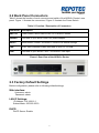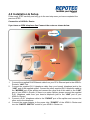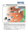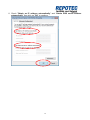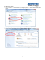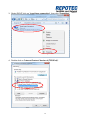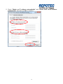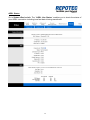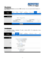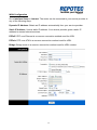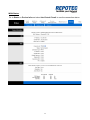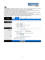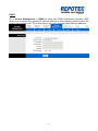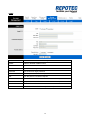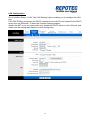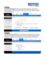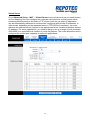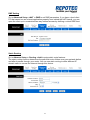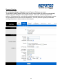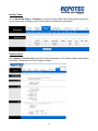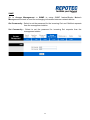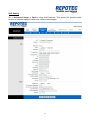
1
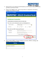
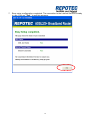
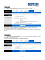
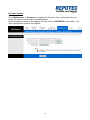
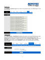
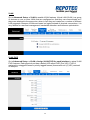
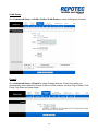
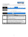
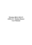
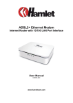
User Manual ADSL2/2+ Broadband Router INDEX 1.0 About This Manual ................................................................................................. 1 1.1 Document Objectives ............................................................................................ 1 1.2 Product Overview ................................................................................................... 1 1.3 Product Description ............................................................................................... 1 2.0 Specification ............................................................................................................. 2 2.1 LED Meaning ........................................................................................................... 3 2.2 Back Panel Connectors ........................................................................................ 4 2.3 Factory Default Settings ....................................................................................... 4 3.0 Hardware Requirements ...................................................................................... 5 3.1 Setting up the Hardware Environment ............................................................. 5 3.2 Powering on ADSL2+ Router.............................................................................. 5 4.0 Installation & Setup ................................................................................................ 6 5.0 Configuration Procedures .................................................................................... 8 6.0 ADSL2+ Router Configuration .......................................................................... 16 7.0 Technology Glossary ........................................................................................... 20 8.0 Introduction of the Web Configuration ........................................................... 23 8.1 Web Configuration Overview ............................................................................ 23 8.2 Accessing ADSL2+ Router Web Configuration ........................................... 23 9.0 Universal Plug-and-Play (UPnP) ..................................................................... 50 9.1 Universal Plug and Play Overview .................................................................. 50 9.2 How do I know if I'm using UPnP? .................................................................. 50 9.3 NAT Traversal ........................................................................................................ 50 9.4 Cautions with UPnP ............................................................................................. 50 9.5 Configuring UPnP................................................................................................. 51 9.6 Installing UPnP in Windows Example ............................................................ 52 9.7 Installing UPnP in Windows Me ....................................................................... 52 9.8 Installing UPnP in Windows XP ....................................................................... 53 9.9 Using UPnP in Windows XP Example ........................................................... 55 9.10 Auto-discover Your UPnP-enabled Network Device ............................... 55 10.0 Web Configuration Easy Access ................................................................... 57 11.0 Troubleshooting .................................................................................................. 60 A.1 Using LEDs to Diagnose Problems ....................................................60 A.1.1 Power LED ......................................................................................60 A.1.2 LAN LED .........................................................................................60 A.1.3 DSL LED ( ACT & LINK) ..................................................................60 A.2 Telnet..................................................................................................61 A.3 Web Configuration .............................................................................61 A.4 Login Username and Password .........................................................62 A.5 LAN Interface .....................................................................................62 A.6 WAN Interface ....................................................................................62 A.7 Internet Access...................................................................................63 A.8 Remote Node Connection ..................................................................63 1.0 About This Manual This manual is developed for users, system managers, network managers, and contains installation, configuration, and operation of the ADSL2+ Router. 1.1 Document Objectives The objectives of this manual are to describe all the initial hardware installation and basic configuration procedure for the ADSL2+ Router. After completing the installation and basic configuration procedures, you can then use the appropriate contents to more completely configure your system. 1.2 Product Overview This section provides an overview of the ADSL2+ Router. It also describes the general applications available with the ADSL2+ Router. Note! This section documents general product features available in the ADSL2+ Router product series. Please refer to the release notes for a current list of upgraded hardware and software specifications. 1.3 Product Description ADSL2+ Router is a low cost, high performance and high-speed device that provides a full rate ADSL2+ Router with the superb reliability and a complete solution for home and office router. ADSL2+ Router can have a maximum downstream data rate of up to 24Mbps and an upstream of up to 1Mbps. When configured as a DHCP server, it will assign IP address to every connected PC and acts as the only externally recognized Internet device on your local area network. With build-in NAT, ADSL2+ Router serves as an Internet firewall, protecting your network from being accessed by outside users. You can safely enjoy the new generation broadband Internet with ADSL2+ Router. 2.0 Specification ADSL Standards supported ● Compliant to ITU-T G.992.1 (G.dmt), G.992.2 (G.lite), G.992.3 (ADSL2), G.992.4 (splitterless ADSL2), G.992.5 (ADSL2+) for Annex A, B ● G.lite (G.992.2) with line rate support of up to 1.5Mbps downstream and 512Kbps upstream. ● Supports Multi-Mode standard (ANSI T1.413, Issue 2; G.dmt (G.992.1); G.994.1 and G.996.1(for ISDN only); G.991.1;G.lite (G992.2)). ● Supports OAM F4/F5 loop-back, AIS and RDI OAM cells. ● ATM Forum UNI 3.1/4.0 PVC. ● Supports up to 8 PVCs (UBR, CBR, VBR). ● Multiple Protocols over AAL5 (RFC 1483). ● PPP over AAL5 (RFC 2364). ● PPP over Ethernet (RFC 2516). Network Address Translation (NAT) Network Address Translation (NAT) allows the translation of an Internet protocol address used within one network (for example a private IP address used in a local network) to a different IP address known within another network (for example a public IP address used on the Internet). Universal Plug and Play (UPnP) Using the standard TCP/IP protocol, the ADSL2+ Router and other UPnP enabled devices can dynamically join a network, obtain an IP address and convey its capabilities to other devices on the network. 10/100M Auto-negotiation Ethernet/Fast Ethernet Interface This auto-negotiation feature allows the ADSL2+ Router to detect the speed of incoming transmissions and adjust appropriately without manual intervention. It allows data transfer of either 10 Mbps or 100 Mbps in either half-duplex or full-duplex mode depending on your Ethernet network. Dynamic DNS Support With Dynamic DNS support, you can have a static hostname alias for a dynamic IP address. Multiple PVC (Permanent Virtual Circuits) Support Your ADSL2+ Router supports up to 8 PVC’s. DHCP Support DHCP (Dynamic Host Configuration Protocol) allows individual clients (computers) to obtain TCP/IP configuration at start-up from a centralized DHCP server. The ADSL2+ Router has built-in DHCP server capability enabled by default. It can assign IP addresses, an IP default gateway and DNS servers to DHCP clients. The ADSL2+ Router can now also act as a surrogate DHCP server (DHCP Relay) where it relays IP address assignment from the actual real DHCP server to the clients. 2 2.1 LED Meaning Your ADSL2+ Router has indicator lights. Please see below for an explanation of the function of each indicator light. Power indicator Ethernet Active indicator ADSL Link indicator Internet Active indicator Table 1. LED function Label Color On Flash Off Green Ready Not Ready Power Off Green Ethernet Connected Transmit / Receive Data Ethernet Disconnected Green Connect to DSLAM Disconnect to DSLAM N/A Green Connect to Internet /IDLE Transmit / Receive Data Disconnect to Internet The icons appear on the products are for application indication only. The trademark or intellectual property is belonging to their respective owners. 3 2.2 Back Panel Connectors Table 2 shows the function of each connector and switch of the ADSL2+ Router’s rear panel. Figure 1. illustrate the connectors / Figure 2. illustrate the Power Switch.. Table 2. Function / Description of Connectors Connector Description SWITCH Power Switch, which used to ON / OFF ADSL2+ Router POWER Connects to your ADSL router 12V power adaptor RESET Reset bottom, RESET the ADSL2+ router to its default settings LAN RJ-45 Jack (Ethernet Cable) connects to your PC, or HUB LINE Connects to your ADSL2+ line – for ADSL2+ Line input Figure1. Rear View of the ADSL2+ Router 2.3 Factory Default Settings Before configuration, please refer to following default settings, Web interface: Username: admin Password: admin LAN IP Settings: IP Address: 192.168.16.1 Subnet Mask: 255.255.255.0 DHCP: DHCP Server: Enable 4 3.0 Hardware Requirements To use ADSL2+ Router, please have following hardware / accessories ready. A PC with Pre-installed Ethernet Adapter (Required) 12V power adaptor (Included in the package) RJ-45 Ethernet cable (Included in the package) RJ-11cable (Included in the package) 3.1 Setting up the Hardware Environment Note! Be sure that you are well insulated from any power source to avoid electricity shock. Please kindly refer to chapter 4.0 “Installation & Setup” 3.2 Powering on ADSL2+ Router Note! Use only the manufacturer-approved power supply that shipped with the ADSL2+ Router. 1. Connect the power to the ADSL2+ Router by plugging the power supply into an appropriate electrical outlet. 2. If the Power LED is off, refer to “Troubleshooting” for information. Please kindly refer to chapter 4.0 “Installation & Setup” 5 4.0 Installation & Setup Follow each STEP carefully and only go to the next step once you have completed the previous STEP. Connection of ADSL2+ Router If you have an ISDN telephone line Connect the router as shown below: 1. 2. 3. 4. Connect the supplied RJ45 Ethernet cable from your PC's Ethernet port to the ADSL2+ Router's “LAN” Port. Connect the supplied RJ11 telephone cable from your home's telephone jack to the “LINE” port of the supplied splitter. Connect the other supplied RJ11 telephone cable to the “MODEM” port of the splitter and connect the other end of this cable to the “LINE” port of your ADSL2+ Router. (If there is no option Splitter, please connect the supplied RJ11 telephone cable from your home's telephone jack to the “LINE” port of your ADSL2+ Router.) Connect a RJ11 telephone cable to the “PHONE” port of the splitter and connect the other end to the telephone. Connect the power adapter to the power inlet “POWER” of the ADSL2+ Router and turn the “ON/OFF SWITCH” switch of your ADSL2+ Router on. 6 If you have a PSTN telephone line (normal analog line) Connect the router as shown below: 1. 2. 3. 4. Connect the supplied RJ45 Ethernet cable from your PC's Ethernet port to ADSL2+ Router's “LAN” Port. Connect the supplied RJ11 telephone cable from your home's telephone jack to the “LINE” port of the supplied splitter. Connect the other supplied RJ11 telephone cable to the “DSL” port of the splitter and connect the other end of this cable to the “LINE” port of your ADSL2+ Router. (If there is no option Splitter, please connect the supplied RJ11 telephone cable from your home's telephone jack to the “LINE” port of your ADSL2+ Router.) Connect a RJ11 telephone cable to the “PHONE” port of the splitter and connect the other end to your telephone. Connect the power adapter to the power inlet “POWER” of the ADSL2+ Router and turn the “ON/OFF SWITCH” switch of your ADSL2+ Router on. 7 5.0 Configuration Procedures Before starting the ADSL2+ Router configuration, please kindly configure the PC computer as below, to have automatic IP address / DNS Server. For Windows 98SE / ME / 2000 / XP 1. Click on “Start” -> “Control Panel” (in Classic View). In the Control Panel, double click on “Network Connections” to continue. 2. Single RIGHT click on “Local Area connection”, then click “Properties”. 8 3. Double click on "Internet Protocol (TCP/ IP)". 4. Check "Obtain an IP address automatically" and “Obtain DNS server address automatically” then click on "OK" to continue. 5. Click "Show icon in notification area when connected" (see screen image in 3. above) then Click on "OK" to complete the setup procedures. 9 For Windows Vista-32/64 1. Click on “Start” -> “Control Panel” -> “View network status and tasks”. 2. In the Manage network connections, click on “Manage network connections” to continue. 10 3. Single RIGHT click on “Local Area connection", then click "Properties". 4. The screen will display the information “User Account Control” and click “Continue” to continue. 5. Double click on "Internet Protocol Version 4 (TCP/IPv4)". 11 6. Check "Obtain an IP address automatically" and “Obtain DNS server address automatically” then click on "OK" to continue. 12 For Windows 7-32/64 1. Click on “Start” -> “Control Panel” (in Category View) -> “View network status and tasks”. 2. In the Control Panel Home, click on “Change adapter settings” to continue. 13 3. Single RIGHT click on “Local Area connection", then click "Properties". 4. Double click on "Internet Protocol Version 4 (TCP/IPv4)". 14 5. Check "Obtain an IP address automatically" and “Obtain DNS server address automatically” then click on "OK" to continue. 15 6.0 ADSL2+ Router Configuration 1. Please insert the supplied CD into your CD-ROM drive. 2. The CD should auto-start, displaying as below. Please click “Run autorun.exe” to continue. If your CD does not start automatically go to Windows Explorer, Select your CD drive and click “autorun.exe”. 3. Please click “Easy Configuration”. 16 4. Enter the VPI, VCI, Username and Password your ISP (Internet Services Provider) provided, and Protocol mode. 5. Please click “Setup” button, when the procedure is completed, it will start to configure the device for a while. 6. Now, checking ADSL 2+ Router hardware connection, ADSL2+ settings, and ADSL2+ Line connection status. 17 7. Easy setup configuration completed. The connection to the Internet Service is ready to use. Click on " Exit " to exit this program. 18 8. Click on " Exit " to exit this program. 9. Now, the ADSL2+ Router has been configured completed, and suitable for Internet Connections. 19 7.0 Technology Glossary 10Base-T An adaptation of the Ethernet standard for Local Area Network (LAN). 10Base-T uses a twisted pair cable with maximum length of 100 meters. AAL ATM Adaptation Layer that defines the rules governing segmentation and reassembly of data into cells. Different AAL types are suited to different traffic classes. Address mask A bit mask used to select bits from an Internet address for subnet addressing. The mask is 32 bits long and selects the network portion of the Internet address and one or more bits of the local portion. Sometimes called subnet mask. ADSL Asymmetric Digital Subscriber Line, as it’s name showing, is an asymmetrical data transmission technology with high traffic rate downstream and low traffic rate upstream. ADSL technology satisfies the bandwidth requirement of applications, which demand “asymmetric” traffic, such as web surfing, file download and Video-on-demand (VOD). ATM Asynchronous Transfer Mode is a layer 2 protocol supporting high-speed asynchronous data with advanced traffic management and quality of service features. bps Bits per second. A standard measurement of digital transmission speeds. Bridge A device that connects two or more physical networks and forwards packets between them. Bridges can usually be made to filter packets, that is, to forward only certain traffic. Related devices are: repeaters which simply forward electrical signals from one cable to the other, and full-fledged routers which make routing decisions based on several criteria. CPE Customer Premises Equipment, such as ADSL router, USB modem. DHCP Dynamic Host Configuration Protocol. Used for assigning dynamic IP address to devices on a network. Used by ISPs for dialup users. DNS Domain Name Server, translates domain names into IP addresses to help user recognize and remember. However, the Internet actually runs on numbered IP addresses, DNS servers needs to translate domain names back to their respective IP addresses. DSL Digital Line Subscriber (DSL) technology provides high-speed access over twisted copper pair for connection to the Internet, LAN interfaces, and to broadband services such as video-on-demand, distance learning, and video conferencing. FTP File Transfer Protocol. The Internet protocol (and program) used to transfer files between hosts. IPoA (RFC 1577) Classical IP and ARP over ATM. Considers ATM configured as a Logic IP Sub-network(LIS) to replace Ethernet local LAN segments. ISP Internet service provider. A company that allows home and corporate users to connect to the Internet. LAN Local area network. A limited distance (typically under a few kilometers or a couple of miles) high-speed network (typically 4 to 100 Mbps) that supports many computers. MAC Media Access Control Layer. A sub-layer of the Data Link Layer (Layer 2) of the ISO OSI Model responsible for media control. MTU Maximum Transmission Unit NAT Network Address Translator as defined by RFC 1631. Enables a LAN to use one set of IP address for internal traffic. A NAT box located where the LAN meets the Internet provides the necessary IP address translation. This helps provide a sort of firewall and allow for a wider address range to be used internally without danger of conflict. PPP Point-to-Point-Protocol. The successor to SLIP, PPP provides router-to-router and host-to-network connections over both synchronous and asynchronous circuits. PPPoA (RFC 2364) The Point-to-Point Protocol(PPP) provides a standard method for transporting multi-protocol datagrams over point-to-point links. This document describes the use of ATM Adaptation Layer 5 (AAL5) for framing PPP encapsulated packets. PPPoE (RFC 2516) This document describes how to build PPP sessions and encapsulate PPP packets over Ethernet. PPP over Ethernet (PPPoE) provides the ability to connect a network of hosts over a simple bridging access device to a remote Access Concentrator. PVC Permanent Virtual Circuit. Connection-oriented permanent leased line circuit between end-stations on a network over a separate ATM circuit. RFC Request for Comments. The document series, begun in 1969, which describes the Internet suite of protocols and related experiments. Not all RFCs describe Internet standards, but all Internet standards 21 are written up as RFCs RFC 1483 Multi-protocol encapsulation over AAL-5. Two encapsulation methods for carrying network interconnect traffic over ATM AAL-5. The first method allows multiplexing of multiple protocols over a single ATM virtual circuit. The protocol of a carried PDU is identified by prefixing the PDU by an IEEE 802.2 Logical Link Control (LLC) header. This method is in the following called "LLC Encapsulation". The second method does higher-layer protocol multiplexing implicitly by ATM Virtual Circuits (VCs). It is in the following called "VC Based Multiplexing". Router A system responsible for making decisions about which of several paths network (or Internet) traffic will follow. To do this, it uses a routing protocol to gain information about the network and algorithms to choose the best route based on several criteria known as "routing metrics. Spanning Tree Spanning-Tree Bridge Protocol (STP). Part of an IEEE standard. A mechanism for detecting and preventing loops from occurring in a multi-bridged environment. When bridges connect three or more LAN segments, a loop can occur. Because a bridge forwards all packets that are not recognized as being local, some packets can circulate for long periods of time, eventually degrading system performance. This algorithm ensures only one path connects any pair of stations, selecting one bridge as the 'root' bridge, with the highest priority one as identifier, from which all paths should radiate. TELNET The virtual terminal protocol in the Internet suite of protocols. Allows users of one host to log into a remote host and act as normal terminal users of that host. VCI Virtual Circuit Identifier. Part of the ATM cell header, a VCI is a tag indicating the channel over which a cell will travel. The VCI of a cell can be changed as it moves between switches via Signaling. VPI Virtual Path Identifier. Part of the ATM cell header, a VPI is a pipe for a number of Virtual Circuits. WAN Wide area network. A data communications network that spans any distance and is usually provided by a public carrier (such as a telephone company or service provider) 22 8.0 Introduction of the Web Configuration 8.1 Web Configuration Overview The embedded web configuration allows you to manage ADSL2+ Router from anywhere through a browser such as Microsoft Internet Explorer or Netscape Navigator. Use Internet Explorer 6.0 and later or Netscape Navigator 7.0 and later versions with JavaScript enabled. It is recommended that you set your screen resolution to 1024 by 768 pixels 8.2 Accessing ADSL2+ Router Web Configuration Step 1. Make sure your ADSL2+ Router is properly connected Step 2. Prepare your computer/computer network to connect to the ADSL2+ Router Step 3. Launch your web browser. Step 4. Type "192.168.16.1" . Step 5. An Enter Network Password window displays. Enter the user name (“admin” is the default), password (“admin” is the default) and click OK. Step 6. You should now see the Site Map screen. 24 Quick Start Guide You can use "Quick Start" to setup the router as follows, and the router will connect to the Internet via ADSL line. Click "Quick Start" to get into the quick setup procedures. Click "RUN WIZARD" to start up this procedure. 25 Step 1 – Please click "Next" to setup your new administrator's password. Step 2 – Please click "Next" to setup your time zone. 26 Step 3 – Please click "Next" to setup your Internet connection type. You can have this information from your Internet Service Provider. Step 4 - Enter the connection information provided by your ISP and click “Next “. 27 Step 5 - Enter the connection information provided by your ISP and click “Next “. Step 6 – Please click “CLOSE “ to finish Quick Start. 28 System Time Go to Maintenance->Time Zone and select system time as you wish. Connecting to a Simple Network Time Protocol (SNTP) server allows the router to synchronize the system clock to the global Internet. The synchronized clock in the router is used to recorded the security log and control client filtering. Admin Setting Go to Maintenance-> Administration to set a new username and password to restrict management access to the router. The default is admin (Username) and admin (Password) 29 Firmware Update Go to Maintenance -> Firmware to upgrade the firmware. The new firmware for your router can improve functionality and performance. Enter the path and name of the upgrade file then click the UPGRADE button below. You will be prompted to confirm the upgrade. 30 System Log Go to Status -> System Log and you can see the system log file. Click “Save Log” to save system log file. System Reset Go to Maintenance -> SysRestart to restart your system.In the event that the router stops responding correctly or in some way stops functioning, you can perform a reset. Your settings will not be changed. To perform the reset, select "Current Setting" and click on the "RESTART" button below. The router will reboot with current setting. Select "Factory Default Setting" and click on the “RESTART” button, the router will reboot with factory default setting. 31 ADSL Status Go to Status->Device Info. The ' ADSL Line Status ' enables you to check the status of your ADSL connection including how fast data is being transferred. 32 ADSL Statistics Go to Status-> Statistics and select ADSL interface. You can see the traffic Statistics of ADSL interface. VC Configuration Go to Interface Setup -> Internet. To add or delete ADSL VC configuration, these information provide by ISP. 33 WAN Configuration Go to Interface Setup -> Internet. The router can be connected to your service provider in any of the following ways. Dynamic IP Address: Obtain an IP address automatically from your service provider. Static IP Address: Uses a static IP address. Your service provider gives a static IP address to access Internet services. PPPoE: PPP over Ethernet is a common connection method used for xDSL PPPoA: PPP over ATM is a common connection method used for xDSL Bridge: Bridge mode is a common connection method used for xDSL modem. 34 WAN Status Go to Status -> Device Info and select the Virtual Circuit to see the connection status. 35 DNS Go to Interface -> LAN to enable DHCP server. Then you can set DNS server for the router. A Domain Name system (DNS) server is like an index of IP addresses and Web addresses. If you type a Web address into you browser, a DNS server will find that name in its index and find the matching IP address. Most ISPs provide a DNS server for speed and convenience. Since your Service Provider many connect to the Internet with dynamic IP settings, it is likely that the DNS server IP addresses are also provided dynamically. However, if there is a DNS server that you would rather use, you need to specify the IP address below. 36 DDNS Go to Access Management -> DDNS to setup your DDNS parameters. Dynamic DNS allows you to update your dynamic IP address with one or many dynamic DNS services. So anyone can access your FTP or Web service on your computer using DNS-like address. 37 CWMP Item Name Description CWMP Enable or Disable TR069 function URL Type ACS server’s URL User Name Type ACS server login username Password Type ACS server login password Path Type the path for Connection request Port Type the port for Connection request Username Type username for ACS server to make connection request Password Type password for ACS server to make connection request Periodic inform Enable or Disable Periodic inform Interval interval time of Periodic inform (unit second). 38 LAN Configuration Go to Interface Setup -> LAN. The 'LAN Settings' option enables you to configure the LAN port. If the DHCP Relay is selected, the DHCP requests from local PCs are forward to the DHCP server runs on WAN side. To have this function working properly, disable the NAT to run on router mode only, disable the DHCP server on the LAN port, and make sure the routing table has the correct routing entry. 39 IP Filtering Go to Access Management -> IP Filtering to block some packets form WAN.The router provides extensive firewall protection by restricting connection parameters to limit the risk of intrusion and defending against a wide array of common hacker attacks. The user can set different IP filter rules of a given protocol(TCP, UDP or ICMP) and a specific direction(incoming, outgoing, or both) to filter the packets. 40 ACL Setting Go to Access Management -> ACL to enable remote management. The user may remotely access the ADSL Router once setting his IP as a Secure IP Address through selected applications. With the default IP 0.0.0.0, any client would be allowed to remotely access the ADSL Router. NAT Setting Go to Advanced Setup->NAT to setup the NAT features. Network Address Translation (NAT) allows multiple users at your local site to access the Internet through a single public IP address or multiple public IP addresses. NAT can also prevent hacker attacks by mapping local addresses to public addresses for key services such as the Web or FTP. 41 Virtual Server Go to Advanced Setup ->NAT -> Virtual Server to set virtual server as you need.(known as Port Mapping).You can configure the router as a virtual server so that remote users accessing services such as the Web or FTP at your local site via public IP addresses can be automatically redirected to local servers configured with private IP addresses. In other words, depending on the requested service (TCP/UDP port numbers), the router redirects the external service request to the appropriate server (located at another internal IP address). For some applications, you need to assign a set or a range of ports (example 4000-5000) to a specified local machine to route the packets. The router allows the user to configure the needed port mappings to suit such applications. 42 DMZ Setting Go to Advanced Setup ->NAT -> DMZ to set DMZ parameters. If you have a local client PC that cannot run an Internet application properly from behind the NAT firewall, you can open the client up to unrestricted two-way Internet access by defining a virtual DMZ Host. Static Routing Go to Advance Setup -> Routing ->Add to setup static route features. The static routing function determines the path that router follows over your network before and after it passes through your router. You can use static routing to allow different IP domain users to access the Internet through this device. 43 Dynamic Routing Go to Interface Setup -> Internet to select Dynamic Route as you need. The dynamic routing feature of the router can be used to allow the router to automatically adjust to physical changes in the network's layout. The router uses the dynamic RIP protocol. It determines the route that the network packets take based on the fewest number of hops between the source and the destination. The RIP protocol regularly broadcasts routing information to other routers on the network. 44 Routing Table Go to Advanced Setup -> Routing to see the Routing Table.The Routing table allows you to see how many routings on your routing table and interface information System Status Go to Status -> Device Info to see the router's information. The System Status page shows the WAN, LAN and the router's firmware version. 45 SNMP Go to Access Management -> SNMP to setup SNMP feature.Simple Network Management Protocol is used for exchanging information between network device. Get Community : Select to set the password for the incoming Get- and GetNext requests from the management station. Set Community : Select to set the password for incoming Set requests from the management station. 46 QoS Setting Go to Advanced Setup -> QoS to setup QoS features. This option will provide better service of selected network traffic over various technologies. 47 VLAN Go to Advanced Setup -> VLAN to enable VLAN features. Virtual LAN (VLAN) is a group of devices on one or more LANs that are configured so that they can communicate as if they were attached to the same wire, when in fact they are located on a number of different LAN segments. Because VLANs are based on logical instead of physical connections, it is very flexible for user/host management, bandwidth allocation and resource optimization.. VLAN PVID Go to Advanced Setup -> VLAN-> Assign VLAN PVID for each interface to setup VLAN PVID features. Each physical port has a default VID called PVID (Port VID). PVID is assigned to untagged frames or priority tagged frames (frames with null (0) VID) received on this port. 48 VLAN Group Go to Advanced Setup -> VLAN-> Define VLAN Group to setup VLAN group features. Firewall Go to Advanced Setup ->Firewall to setup Firewall features. Select this option can automatically detect and block Denial of Service (DoS) attacks, such as Ping of Death, SYN Flood, Port Scan and Land Attack. 49 9.0 Universal Plug-and-Play (UPnP) 9.1 Universal Plug and Play Overview Universal Plug and Play (UPnP) is a distributed, open networking standard that uses TCP/IP for simple peer-to-peer network connectivity between devices. An UPnP device can dynamically join a network, obtain an IP address, convey its capabilities and learn about other devices on the network. In turn, a device can leave a network smoothly and automatically when it is no longer in use. 9.2 How do I know if I'm using UPnP? UPnP hardware is identified as an icon in the Network Connections folder (Windows XP). Each UPnP compatible device installed on your network will appear as a separate icon. Selecting the icon of a UPnP device will allow you to access the information and properties of that device. 9.3 NAT Traversal UPnP NAT traversal automates the process of allowing an application to operate through NAT. UPnP network devices can automatically configure network addressing, announce their presence in the network to other UPnP devices and enable exchange of simple product and service descriptions. NAT traversal allows the following: Dynamic port mapping Learning public IP addresses Assigning lease times to mappings Windows Messenger is an example of an application that supports NAT traversal and UPnP. See the Network Address Translation (NAT) chapter for further information about NAT. 9.4 Cautions with UPnP The automated nature of NAT traversal applications in establishing their own services may present network security issues. Network information and configuration may also be obtained and modified by users in some network environments. All UPnP-enabled devices may communicate freely with each other without additional configuration. Disable UPnP if this is not your intention. UPnP broadcasts are only allowed on the LAN. See later sections for examples of installing UPnP in Windows XP and Windows Me as well as an example of using UPnP in Windows. 50 9.5 Configuring UPnP From the Site Map in the main menu, click UPnP under Access Managemen to display the screen shown next. The following table describes the labels in this screen. LABEL DESCRIPTION UPnP Select this checkbox to activate UPnP. Be aware that anyone could use a UPnP application to open the web configuration's login screen without entering ADSL2+ Router's IP address (although you must still enter the password to access the web configuration). Auto configured Select this check box to allow UPnP-enabled applications to automatically configure ADSL2+ Router so that they can communicate through ADSL2+ Router, for example by using NAT traversal, UPnP applications automatically reserve a NAT forwarding port in order to communicate with another UPnP enabled device; this eliminates the need to manually configure port forwarding for the UPnP enabled application. Apply Click Apply to save your settings back to home screen. 51 9.6 Installing UPnP in Windows Example This section shows how to install UPnP in Windows Me and Windows XP. 9.7 Installing UPnP in Windows Me Follow the steps below to install the UPnP in Windows Me. Step 1. Click Start and Control Panel. Double-click Add/Remove Programs. Step 2. Click on the Windows Setup tab and select Communication in the Components selection box. Click Details. Step 3. In the Communications window, select the Universal Plug and Play check box in the Components selection box. Step 4. Click OK to go back to the Add/Remove Programs Properties window and click Next. Step 5. Restart the computer when prompted. 52 9.8 Installing UPnP in Windows XP Follow the steps below to install the UPnP in Windows XP. Step 1. Click Start and Control Panel. Step 2. Double-click Network Connections. Step 3. In the Network Connections window, click Advanced in the main menu and select Optional Networking Components …. The Windows Optional Networking Components Wizard window displays. Step 4. Select Networking Service in the Components selection box and click Details. 53 Step 5. In the Networking Services window, select the Universal Plug and Play check box. Step 6. Click OK to go back to the Windows Optional Networking Component Wizard window and click Next. 54 9.9 Using UPnP in Windows XP Example This section shows you how to use the UPnP feature in Windows XP. You must already have UPnP installed in Windows XP and UPnP activated on ADSL2+ Router. Make sure the computer is connected to a LAN port of ADSL2+ Router. Turn on your computer and ADSL2+ Router. 9.10 Auto-discover Your UPnP-enabled Network Device Step 1. Click start and Control Panel. Double-click Network Connections. An icon displays under Internet Gateway. Step 2. Right-click the icon and select Properties. Step 3. In the Internet Connection Properties window, click Settings to see the port mappings there were automatically created. 55 Step 4. You may edit or delete the port mappings or click Add to manually add port mappings. Step 5. Select Show icon in notification area when connected option and click OK. An icon displays in the system tray Step 6. Double-click on the icon to display your current Internet connection status. 56 10.0 Web Configuration Easy Access With UPnP, you can access the web-based configuration on ADSL2+ Router without finding out the IP address of ADSL2+ Router first. This comes helpful if you do not know the IP address of ADSL2+ Router. Follow the steps below to access the web configuration. Step 1. Click Start and then Control Panel. Step 2. Double-click Network Connections. Step 3. Select My Network Places under Other Places. 57 Step 4.An icon with the description for each UPnP-enabled device displays under Local Network. Step 5. Right-click on the icon for yourADSL2+ Router and select Invoke. The web configuration login screen displays. 58 Step 6. Right-click on the icon for yourADSL2+ Router and select Properties. A properties window displays with basic information about ADSL2+ Router. 59 11.0 Troubleshooting A.1 Using LEDs to Diagnose Problems The LEDs are useful aides for finding possible problem causes. A.1.1 Power LED The PWR LED on the front panel does not light up. STEPS CORRECTIVE ACTION 1 Make sure that ADSL2+ Router’s power adaptor is connected to ADSL2+ Router and plugged in to an appropriate power source. Use only the supplied power adaptor. 2 Check that ADSL2+ Router and the power source are both turned on and ADSL2+ Router is receiving sufficient power. 3 Turn the ADSL2+ Router off and on. 4 If the error persists, you may have a hardware problem. In this case, you should contact your vendor. A.1.2 LAN LED The LAN LED on the front panel does not light up. STEPS CORRECTIVE ACTION 1 Check the Ethernet cable connections between your ADSL2+ Router and the computer or hub. 2 Check for faulty Ethernet cables. 3 Make sure your computer’s Ethernet card is working properly. 4 If these steps fail to correct the problem, contact your local distributor for assistance. A.1.3 DSL LED ( ACT & LINK) The DSL LED on the front panel does not light up. STEPS CORRECTIVE ACTION 1 Check the telephone wire and connections between ADSL2+ Router DSL port and the wall jack. 2 Make sure that the telephone company has checked your phone line and set it up for DSL service. 3 Reset your ADSL line to reinitialize your link to the DSLAM. 4 If these steps fail to correct the problem, contact your local distributor for assistance. 60 A.2 Telnet I cannot telnet into ADSL2+ Router. STEPS CORRECTIVE ACTION 1 Check the LAN port and the other Ethernet connections. 2 Make sure you are using the correct IP address of ADSL2+ Router. Check the IP address of ADSL2+ Router. 3 Ping ADSL2+ Router from your computer. If you cannot ping ADSL2+ Router, check the IP addresses of ADSL2+ Router and your computer. Make sure your computer is set to get a dynamic IP address; or if you want to use a static IP address on your computer, make sure that it is on the same subnet as ADSL2+ Router. 4 Make sure you entered the correct password. The default password is “admin”. 5 If these steps fail to correct the problem, contact the distributor. A.3 Web Configuration I cannot access the web configuration. STEPS CORRECTIVE ACTION 1 Make sure you are using the correct IP address of ADSL2+ Router. Check the IP address of ADSL2+ Router. 2 Make sure that there is not a console session running. 3 Check that you have enabled web service access. If you have configured a secured client IP address, your computer’s IP address must match it. 4 For WAN access, you must configure remote management to allow server access from the Wan (or all). 5 Your computer’s and ADSL2+ Router’s IP addresses must be on the same subnet for LAN access. 6 If you changed ADSL2+ Router’s LAN IP address, then enter the new one as the URL. 7 Remove any filters in LAN or WAN that block web service. The web configuration does not display properly. STEPS CORRECTIVE ACTION 1 Make sure you are using Internet Explorer 5.0 and later versions. 2 Delete the temporary web files and log in again. In Internet Explorer, click Tools, Internet Options and then click the Delete Files ... button. When a Delete Files window displays, select Delete all offline content and click OK. (Steps may vary depending on the version of your Internet browser.) 61 A.4 Login Username and Password I forgot my login username and/or password. STEPS CORRECTIVE ACTION 1 If you have changed the password and have now forgotten it, you will need to upload the default configuration file. This will erase all custom configurations and restore all of the factory defaults including the password. 2 Press the RST button for five seconds, and then release it. When the LINK LED begins to blink, the defaults have been restored and ADSL2+ Router restarts. 3 The default username is “admin”. The default password is “admin”. The Password and Username fields are case-sensitive. Make sure that you enter the correct password and username using the proper casing. 4 It is highly recommended to change the default username and password. Make sure you store the username and password in a save place. A.5 LAN Interface I cannot access ADSL2+ Router from the LAN or ping any computer on the LAN. STEPS CORRECTIVE ACTION 1 Check the Ethernet LEDs on the front panel. A LAN LED should be on if the port is connected to a computer or hub. If the LAN LEDs on the front panel are off, refer to Section A.1.2. 2 Make sure that the IP address and the subnet mask of ADSL2+ Router and your computer(s) are on the same subnet. A.6 WAN Interface Initialization of the ADSL connection failed. STEPS CORRECTIVE ACTION 1 Check the cable connections between the ADSL port and the wall jack. The DSL LEDs on the front panel of ADSL2+ Router should be on. 2 Check that your VPI, VCI, type of encapsulation and type of multiplexing settings are the same as what you collected from your telephone company and ISP. 3 Restart ADSL2+ Router. If you still have problems, you may need to verify your VPI, VCI, type of encapsulation and type of multiplexing settings with the telephone company and ISP. I cannot get a WAN IP address from the ISP. STEPS CORRECTIVE ACTION 1 The ISP provides the WAN IP address after authenticating you. Authentication may be through the user name and password, the MAC address or the host name. 62 2 The username and password apply to PPPoE and PPoA encapsulation only. Make sure that you have entered the correct Service Type, User Name and Password (be sure to use the correct casing). A.7 Internet Access I cannot access the Internet. STEPS CORRECTIVE ACTION 1 Make sure ADSL2+ Router is turned on and connected to the network. 2 If the DSL LEDs are off, refer to Section A.1.3. 3 Verify your WAN settings. 4 Make sure you entered the correct user name and password. Internet connection disconnects. STEPS CORRECTIVE ACTION 1 Check the schedule rules. 2 If you use PPPoA or PPPoE encapsulation, check the idle time-out setting. 3 Contact your ISP. A.8 Remote Node Connection I cannot connect to a remote node or ISP. STEPS CORRECTIVE ACTION 1 Check WAN screen to verify that the username and password are entered properly. 2 Verify your login name and password for the remote node. 3 If these steps fail, you may need to verify your login and password with your ISP. 63