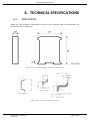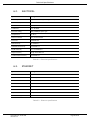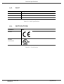
1
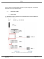
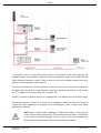
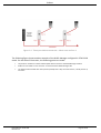
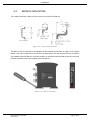
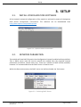
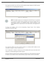
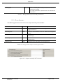
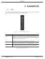
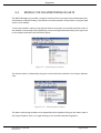
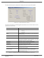
DHCP Manger
User Manual
A-DHCP
Document No. D111-009
08/2015
Revision 1.1
Preface
CONTENTS
1.
Preface ............................................................................................................................... 4
1.1.
2.
3.
4.
Introduction to the DHCP Manager ............................................................................ 4
1.1.1.
DHCP .................................................................................................................... 4
1.1.2.
Location Co-ordinated IP Address Assignment.................................................... 4
1.2.
Features ....................................................................................................................... 5
1.3.
Architecture................................................................................................................. 7
1.3.1.
Normal Mode ....................................................................................................... 7
1.3.2.
ETAP-Child Mode ................................................................................................. 8
1.4.
Additional Information .............................................................................................. 12
1.5.
Support ...................................................................................................................... 12
Installation ....................................................................................................................... 13
2.1.
Module Layout .......................................................................................................... 13
2.2.
Module Mounting ..................................................................................................... 15
2.3.
Power ........................................................................................................................ 16
2.4.
Ethernet Port ............................................................................................................. 16
Setup ................................................................................................................................ 17
3.1.
Install Configuration Software .................................................................................. 17
3.2.
Network Parameters ................................................................................................. 17
3.3.
Creating a New Project.............................................................................................. 22
3.4.
DHCP Manager parameters ...................................................................................... 24
3.5.
Module Download ..................................................................................................... 28
3.6.
RSLogix 5000 Configuration ...................................................................................... 31
3.6.1.
Add Module to I/O Configuration ...................................................................... 31
3.6.2.
Importing UDTs and Mapping Routines ............................................................ 33
Operation ......................................................................................................................... 35
4.1.
Scanning .................................................................................................................... 35
4.2.
Assignment ................................................................................................................ 35
4.2.1.
Assignment – Normal Mode .............................................................................. 35
4.2.2.
Assignment – ETAP-Child Mode......................................................................... 35
4.3.
RSLogix 5000 assemblies ........................................................................................... 36
1.1.1.
Input Assembly................................................................................................... 37
Document No. D111-009
Revision 1.1
Page 2 of 50
Preface
1.1.2.
5.
6.
7.
Output Assembly................................................................................................ 39
Diagnostics ....................................................................................................................... 40
5.1.
LEDs ........................................................................................................................... 40
5.2.
Module Status Monitoring in Slate ........................................................................... 41
5.3.
Module Event Log...................................................................................................... 45
5.4.
Web Server ................................................................................................................ 46
Technical Specifications ................................................................................................... 47
6.1.
Dimensions ................................................................................................................ 47
6.2.
Electrical .................................................................................................................... 48
6.3.
Ethernet..................................................................................................................... 48
6.4.
DHCP .......................................................................................................................... 49
6.5.
Certifications ............................................................................................................. 49
Index................................................................................................................................. 50
Revision History
Revision
Date
1.0
26 June 2015
1.1
25 August 2015
Document No. D111-009
Revision 1.1
Comment
Initial document
Add UL Listed mark
Page 3 of 50
Preface
1. PREFACE
1.1.
INTRODUCTION TO THE DHCP MANAGER
This manual describes the installation, operation, and diagnostics of the Aparian DHCP
Manager module.
The DHCP Manager provides location co-ordinated IP Address assignment to DLR capable
(embedded switch) devices connected in a linear topology. In applications where different
sub-systems can be connected in any order, the module ensures that their IP addresses are
assigned in the order in which they are located. Examples of this application can be found in
the packaging industry.
1.1.1. DHCP
The Dynamic Host Configuration Protocol (DHCP) is a standard network protocol that is
capable of dynamically assigning IP addresses and other network parameters to any device
on the network that requests it. This significantly reduces the effort required by network
administrators. An IP address pool is provisioned to the DHCP server, and it will assign these
IP addresses incrementally typically using a first-come-first-served methodology. Additional
network parameters including subnet masks, default gateways etc. can also be assigned by
the DHCP server.
1.1.2. LOCATION CO-ORDINATED IP ADDRESS ASSIGNMENT
In traditional DHCP assignment, the IP Address assignment for devices typically follows the
order in which they are connected or powered up.
With the Aparian DHCP Manager, the IP Addresses are assigned to match the physical location
or position on the linear network.
Document No. D111-009
Revision 1.1
Page 4 of 50
Preface
Figure 1.1. – Typical Setup
1.2.
FEATURES
The DHCP Manager is able to serve IP addresses to devices that are not directly part of the
embedded switch linear topology. Such devices could either be connected at the end of the
network, or be connected using 3 port devices such as ETAP modules.
There are two strategies or modes that control the assignment of these devices:
•
Normal mode
•
ETAP-Child mode.
Depending on the mode, different classes of devices are assigned IP addresses from one of
the three different IP ranges configured in the module.
The different classes of modules are defined as follows:
Document No. D111-009
Revision 1.1
Page 5 of 50
Preface
Device Class
Description
Ordered
Devices that are embedded switch, Device-Level-Ring capable,
devices connected in the linear network.
IP addresses are assigned from the Ordered IP range.
Child
Devices that are connected to the third port of a three-port device
(e.g. ETAP) located on the linear network. This class of device is only
valid in the ETAP-Child mode.
Only one child can exist for each three-port device. Any additional
devices found connected to that port will be defined as visitors and
not children.
IP addresses are assigned from the Child IP range.
Visitor
All other devices that are connected to the network will be visitors.
These included multiple modules connected off a three-port device,
or non-DLR devices connected to the end of the linear network.
IP addresses are assigned from the Visitor IP range.
Table 1.1 - Device Classes
Mode
Normal
ETAP-Child
Description
All devices in the linear topology (including three port devices) are
assigned location co-ordinated IP addresses from the Ordered IP
range.
All other devices are assigned IP addresses from the Visitor IP range.
All devices in the linear topology (including three port devices) are
assigned location co-ordinated IP addresses from the Ordered IP
range.
Each child (device connected to the third port of a three-port device)
will be assigned an IP address from the Child IP range. The offset
within the Child IP range will be equal to that of the offset of the
parent three-port device in the ordered range.
For example, if an ETAP is the 5th device in the linear network, it will
be assigned the 5th IP address in the Ordered IP range. Its child will
be assigned the 5th IP address in the Child IP range, irrespective of
how many preceding children there are.
All other devices are assigned IP addresses from the Visitor IP range.
Table 1.2. – Modes of Operation
The DHCP Manager module is configured using the Aparian Slate application. This program can
be downloaded from www.aparian.com free of charge.
Hereafter the DHCP Manager will be referred to as the module.
The module can operate in both a Logix “owned” and standalone mode. With a Logix
connection the input and output assemblies will provide direct control and additional
diagnostics information which will be available in the Logix controller environment.
Document No. D111-009
Revision 1.1
Page 6 of 50
Preface
A built-in webserver provides detailed diagnostics of system configuration and operation,
without the need for any additional software.
1.3.
ARCHITECTURE
1.3.1. NORMAL MODE
The figure below provides an example of the typical network setup in Normal mode with the
following IP ranges configured:
Ordered:
Visitor:
192.168.1.1 – 192.168.1.99
192.168.1.201 – 192.168.1.230
Figure 1.2. - Example of a network setup in Normal mode
Document No. D111-009
Revision 1.1
Page 7 of 50
Preface
In this mode all the devices in the linear topology are assigned location co-ordinated IP
addresses from the Ordered IP range, this includes the ETAP located at position 2. The first
device in the linear network receives the first IP address in the Ordered IP range and so on.
Both operator panels are not directly part of the linear network and are assigned addresses
IP addresses from the Visitor IP range.
NOTE: The visitor addresses are assigned in the chronological order in which their
DHCP requests are received. Therefor any correlation between their IP address
and their physical location would be coincidental. Even though the device at IP
address 192.168.1.201 is connected at the end of the linear network, it is classed
as a visitor because it is not a DLR capable device.
1.3.2. ETAP-CHILD MODE
The ETAP-Child mode is illustrated in the figure below, with the following IP ranges configured
Ordered:
192.168.1.1 – 192.168.1.99
Child:
192.168.1.101 – 192.168.1.199
Visitor:
192.168.1.201 – 192.168.1.230
Document No. D111-009
Revision 1.1
Page 8 of 50
Preface
Figure 1.3 – Example setup of network in ETAP-Child Mode
In this mode, similar to that of the normal mode, all the devices in the linear topology are
assigned location co-ordinated IP addresses from the Ordered IP range, this includes the two
ETAPs located at positions 2 and 3. The first device in the linear network receives the first IP
address in the Ordered IP range and so on.
The drive connected to the ETAP at position 2, meets the criteria of a child and is assigned an
IP address from the Child IP range. Because its parent is located at position 2, it will receive
the 2nd IP address in the Child range, viz. 192.168.1.102.
Similarly, the drive located at position 3 is assigned the 3rd IP address from the Child IP range.
The operator panel is classed as a visitor and is assigned an addresses from the Visitor IP
range. The visitor addresses are assigned in the chronological order in which their DHCP
requests are received.
NOTE: When using the DHCP Manager in ETAP-Child mode it is important to
connect the three-port devices (e.g. ETAP modules) so that Port 1 is connected
on the side of the DHCP Manager. Failure to do so will result in assignment
failure and may require device ports to be manually re-enabled.
Document No. D111-009
Revision 1.1
Page 9 of 50
Preface
Figure 1.4 - Three-port device connection – Must enter on Port 1
The following figure shows another example of the DHCP Manager configured in ETAP-Child
mode. For the sake of illustration, the following points are made:
•
The positons number from the first DLR capable device nearest to the DHCP Manager module.
•
ETAPs are connected so as to have Port 1 connected to the DHCP Manager side.
•
The Child positions follow after their parents (ETAPS) that is why the second drive, is Child position 4,
and not 3.
Document No. D111-009
Revision 1.1
Page 10 of 50
Preface
Figure 1.5 - Example setup of network in ETAP-Child Mode
Document No. D111-009
Revision 1.1
Page 11 of 50
Preface
1.4.
ADDITIONAL INFORMATION
The following documents contain additional information that can assist the user with the
module installation and operation.
Resource
Link
Slate Installation
http://www.aparian.com/software/slate
DHCP Manager User Manual
DHCP Manager Datasheet
Example Code & UDTs
http://www.aparian.com/products/dhcpmanager
Ethernet wiring standard
www.cisco.com/c/en/us/td/docs/video/cds/cde/cde205_220_420/installation/guide/
cde205_220_420_hig/Connectors.html
CIP Routing
The CIP Networks Library, Volume 1, Appendix C:Data Management
Table 1.3. - Additional Information
1.5.
SUPPORT
Technical support is provided via the Web (in the form of user manuals, FAQ, datasheets etc.)
to assist with installation, operation, and diagnostics.
For additional support the user can use either of the following:
Resource
Link
Contact Us web link
www.aparian.com/contact-us
Support email
[email protected]
Table 1.4. – Support Details
Document No. D111-009
Revision 1.1
Page 12 of 50
Installation
2. INSTALLATION
2.1.
MODULE LAYOUT
The module has three ports at the bottom of the enclosure as shown in the figure below. The
ports are used for Ethernet, RS232 serial, and power. The power port uses a three way
connector which is used for the DC power supply positive and negative (or ground) voltage as
well as the earth connection.
NOTE: The RS232 for this module is reserved and should not be used.
The Ethernet cable must be wired according to industry standards which can be found in the
additional information section of this document.
Figure 2.1. – DHCP Manager side and bottom view
The module provides three diagnostic LEDs as shown in the front view figure below. These
LEDs are used to provide information regarding the module system operation and the
Ethernet interface.
Document No. D111-009
Revision 1.1
Page 13 of 50
Installation
Figure 2.2. – DHCP Manager front and top view
The module provides four DIP switches at the top of the enclosure as shown in the top view
figure above.
DIP Switch
Description
DIP Switch 1
Used to force the module into “Safe Mode”. When in “Safe Mode” the module will not
load the application firmware and will wait for new firmware to be downloaded. This
should only be used in the rare occasion when a firmware update was interrupted at
a critical stage.
DIP Switch 2
This will force the module into DHCP mode which is useful when the user has forgotten
the IP address of the module.
DIP Switch 3
Reserved
DIP Switch 4
Reserved
Table 2.1. - DIP Switch Settings
Document No. D111-009
Revision 1.1
Page 14 of 50
Installation
2.2.
MODULE MOUNTING
The module provides a DIN rail clip to mount onto a 35mm DIN rail.
Figure 2.3 - DIN rail specification
The DIN rail clip is mounted on the bottom of the module at the back as shown in the figure
below. Use a flat screw driver to pull the clip downward. This will enable the user to mount
the module onto the DIN rail. Once the module is mounted onto the DIN rail the clip must be
pushed upwards to lock the module onto the DIN rail.
Figure 2.4 - DIN rail mouting
Document No. D111-009
Revision 1.1
Page 15 of 50
Installation
2.3.
POWER
A three way power connector is used to connect Power+, Power– (GND), and earth. The
module requires an input voltage of 10 – 28Vdc. Refer to the technical specifications section
in this document.
Figure 2.5 - Power connector
2.4.
ETHERNET PORT
The Ethernet connector should be wired according to industry standards. Refer to the
additional information section in this document for further details.
Document No. D111-009
Revision 1.1
Page 16 of 50
Setup
3. SETUP
3.1.
INSTALL CONFIGURATION SOFTWARE
All the network setup and configuration of the module is achieved by means of the Aparian
Slate device configuration environment. This software can be downloaded from
http://www.aparian.com/software/slate.
Figure 3.1. - Aparian Slate Environment
3.2.
NETWORK PARAMETERS
The module will have DHCP (Dynamic Host Configuration Protocol) enabled as factory default.
Thus a DHCP server must be used to provide the module with the required network
parameters (IP address, subnet mask, etc.). There are a number of DHCP utilities available,
however it is recommended that the DHCP server in Slate be used.
Within the Slate environment, the DHCP server can be found under the Tools menu.
Figure 3.2. - Selecting DHCP Server
Document No. D111-009
Revision 1.1
Page 17 of 50
Setup
Once opened, the DHCP server will listen on all available network adapters for DHCP requests
and display their corresponding MAC addresses.
Figure 3.3. - DHCP Server
NOTE: If the DHCP requests are not displayed in the DHCP Server it may be due
to the local PC’s firewall. During installation the necessary firewall rules are
automatically created for the Windows firewall. Another possibility is that
another DHCP Server is operational on the network and it has assigned the IP
address.
To assign an IP address, click on the corresponding “Assign” button. The IP Address
Assignment window will open.
Figure 3.4. - Assigning IP Address
The required IP address can then be either entered, or a recently used IP address can be
selected by clicking on an item in the Recent List.
If the “Enable Static” checkbox is checked, then the IP address will be set to static after the IP
assignment, thereby disabling future DHCP requests.
Once the IP address window has been accepted, the DHCP server will automatically assign the
IP address to the module and then read the Identity object Product name from the device.
Document No. D111-009
Revision 1.1
Page 18 of 50
Setup
The successful assignment of the IP address by the device is indicated by the green
background of the associated row.
Figure 3.5. - Successful IP address assignment
It is possible to force the module back into DHCP mode by powering up the device with DIP
switch 2 set to the On position.
A new IP address can then be assigned by repeating the previous steps.
NOTE: It is important to return DIP switch 2 back to Off position, to avoid the
module returning to a DHCP mode after the power is cycled again.
If the module’s DIP switch 2 is in the On position during the address assignment, the user will
be warned by the following message.
Figure 3.6. - Force DHCP warning
In addition to the setting the IP address, a number of other network parameters can be set
during the DHCP process. These settings can be viewed and edited in Slate’s Application
Settings, in the DHCP Server tab.
Once the DHCP process has been completed, the network settings can be set using the
Ethernet Port Configuration via the Target Browser.
The Target Browser can be accessed under the Tools menu.
Document No. D111-009
Revision 1.1
Page 19 of 50
Setup
Figure 3.7. - Selecting the Target Browser
The Target Browser automatically scans the Ethernet network for EtherNet/IP devices.
Figure 3.8. - Target Browser
Right-clicking on a device, reveals the context menu, including the Port Configuration option.
Figure 3.9. - Selecting Port Configuration
Document No. D111-009
Revision 1.1
Page 20 of 50
Setup
All the relevant Ethernet port configuration parameters can be modified using the Port
Configuration window.
Figure 3.10. - Port Configuration
Alternatively, these parameters can be modified using Rockwell Automation’s RSLinx
software.
Document No. D111-009
Revision 1.1
Page 21 of 50
Setup
3.3.
CREATING A NEW PROJECT
Before the user can configure the module, a new Slate project must be created. Under the
File menu, select New.
Figure 3.11. - Creating a new project
A Slate project will be created, showing the Project Explorer tree view. To save the project
use the Save option under the File menu.
A new device can now be added by selecting Add under the Device menu.
Figure 3.12. - Adding a new device
In the Add New Device window select the DHCP Manager, and click the Ok button.
Document No. D111-009
Revision 1.1
Page 22 of 50
Setup
Figure 3.13 – Selecting a new DHCP Manager
The device will appear in the Project Explorer tree as shown below, and its configuration
window opened.
The device configuration window can be reopened by either double clicking the module in
the Project Explorer tree or right-clicking the module and selecting Configuration.
Figure 3.14. – DHCP Manager configuration
Refer to the additional information section in this document for Slate’s installation and
operation documentation.
Document No. D111-009
Revision 1.1
Page 23 of 50
Setup
3.4.
DHCP MANAGER PARAMETERS
The DHCP Manager parameters will be configured by Slate. Refer to the additional
information section for documentation and installation links for Aparian Slate. The parameter
configuration consists of a general configuration, DHCP Manager and an Advanced
configuration tab. When downloading this configuration into the module it will be saved in
non-volatile memory that persists when the module is powered down.
NOTE: When a firmware upgrade is performed the module will clear all the
DHCP Manager’s configuration parameters.
The general configuration consists of the following parameters:
Parameter
Description
Instance Name
This parameter is a user defined name to differentiate between various DHCP
Managers.
Description
This parameter is used to provide a more detail description of the application for the
module.
Major Revision
The major revision of the module
Mode
The mode will determine how the DHCP manager assigns IP addresses to different
devices.
Normal Mode
All devices in the linear topology (including three port devices) are assigned location
co-ordinated IP addresses from the Ordered IP range.
All other devices are assigned IP addresses from the Visitor IP range.
ETAP-Child Mode
All devices in the linear topology (including three port devices) are assigned location
co-ordinated IP addresses from the Ordered IP range.
Each child (device connected to the third port of a three-port device) will be assigned
an IP address from the Child IP range. The offset within the Child IP range will be equal
to that of the offset of the parent three-port device in the ordered range.
For example, if an ETAP is the 5th device in the linear network, it will be assigned the
5th IP address in the Ordered IP range. Its child will be assigned the 5th IP address in
the Child IP range, irrespective of how many preceding children there are.
All other devices are assigned IP addresses from the Visitor IP range.
Table 3.1 - General configuration parameters
The general configuration is shown in the figure below. The DHCP Manager’s general
configuration window is opened by either double clicking on the module in the tree or rightclicking the module and selecting Configuration.
Document No. D111-009
Revision 1.1
Page 24 of 50
Setup
Figure 3.15. - General Configuration
The DHCP configuration consists of the following parameters:
Parameter
Description
Ordered IP Range
The IP range, defined by a start and end IP address, to be used in the assignment
of DLR-capable devices connected in the linear network.
Child IP Range
The IP range, defined by a start and end IP address, to be used in the assignment
of Child devices connected on the network.
A Child device is a device connected to the third port of a three-port device which
is connected on the linear network.
This range is only applicable in the ETAP-Child mode.
Visitor IP Range
The IP range, defined by a start and end IP address, to be used in the assignment
of all visitor devices connected on the network.
A visitor device, is one which is neither an ordered nor a child device.
Master Subnet
The master subnet mask, is the subnet mask assigned to all devices.
Note: Care must be taken to select a subnet mask that allows all devices from the
different IP ranges to communicate with one another, and with the DHCP
Manager itself.
Table 3.2 – DHCP configuration parameters
The DHCP configuration is shown in the figure below. The DHCP configuration window is
opened by either double clicking on the module in the tree or right-clicking the module and
selecting Configuration. Once in the configuration window select the second tab at the top
DHCP Manager.
Document No. D111-009
Revision 1.1
Page 25 of 50
Setup
Figure 3.16. – DHCP Manager Configuration
The Advanced configuration consists of the DHCP Assignment and DHCP Lease parameters.
The DHCP Assignment parameters are as follows:
Parameter
Description
Ordered TimeOut
The allocated time (in milliseconds) to process any DHCP requests from Ordered
devices.
Child TimeOut
The allocated time (in milliseconds) to process any DHCP requests from Child
devices.
Relevant only in ETAP-Child mode.
Visitor TimeOut
The allocated time (in milliseconds) to process any DHCP requests from Visitor
devices.
Port Recovery Time
The time delay (in milliseconds) after re-opening a three-port device port to allow
Ethernet link to be established.
Relevant only in ETAP-Child mode.
Table 3.3 – DHCP Assignment parameters
Document No. D111-009
Revision 1.1
Page 26 of 50
Setup
The DHCP Lease parameters are as follows:
Parameter
Description
DHCP Renewal Time
The time (in seconds) before the client begins to renew its address lease with the
DHCP Manager.
This parameter is transmitted to the device during the DHCP assignment.
A value of 0xFFFFFFFF is used to indicate infinity.
DHCP Rebinding Time
The time (in seconds) before the client enters the rebinding state if it has not
renewed its current address lease with the DHCP Manager.
This parameter is transmitted to the device during the DHCP assignment.
A value of 0xFFFFFFFF is used to indicate infinity.
DHCP Lease Time
The duration that the IP address is leased to the client (in seconds).
This parameter is transmitted to the device during the DHCP assignment.
A value of 0xFFFFFFFF is used to indicate infinity.
Table 3.4 – DHCP Lease parameters
Figure 3.17 – DHCP Advanced configuration
Document No. D111-009
Revision 1.1
Page 27 of 50
Setup
3.5.
MODULE DOWNLOAD
Once the DHCP Manager configuration has been completed, it must be downloaded to the
module.
Before downloading the Connection Path of the module should be set. This path will
automatically default to the IP address of the module, as set in the module configuration. It
can however be modified, if the DHCP Manager is not on a local network.
The Connection path can be set by right-clicking on the module and selecting the Connection
Path option.
Figure 3.18. - Selecting Connection Path
The new connection path can then be either entered manually or selected by means of the
Target Browser.
Figure 3.19. - Connection Path
To initiate the download, right-click on the module and select the Download option.
Document No. D111-009
Revision 1.1
Page 28 of 50
Setup
Figure 3.20. - Selecting Download
Once complete, the user will be notified that the download was successful.
Figure 3.21. - Successful download
During the download process the module’s time will be compared to that of the PC’s time.
Should the difference be greater than 30 seconds, the user will be prompted to set the
module time to that of the PC time.
Figure 3.22. – Setting module time
The module time is used only for the event log.
Within the Slate environment the module will be in the Online state, indicated by the green
circle around the module.
The module is now configured and will start operating immediately.
Document No. D111-009
Revision 1.1
Page 29 of 50
Setup
Figure 3.23. - Module online
Document No. D111-009
Revision 1.1
Page 30 of 50
Setup
3.6.
RSLOGIX 5000 CONFIGURATION
3.6.1. ADD MODULE TO I/O CONFIGURATION
The module can operate in both a Logix “owned” and standalone mode. When the module
operates in a Logix “owned” mode the DHCP Manager will need to be added to the RSLogix
5000 IO tree. The module will need to be added as a generic Ethernet module. This is done by
right clicking on the Ethernet Bridge in the RSLogix 5000 and selecting New Module after
which the ETHERNET-MODULE is selected to be added as shown in the figure below.
NOTE: See the next section for importing the configuration (L5X).
Figure 3.24 - Add a Generic Ethernet Module in RSLogix 5000
The user must enter the IP address of the DHCP Manager that will be used. The assembly
instance and size must also be added for the input, output, and configuration in the
connection parameters section. Below are the required connection parameters.
Connection Parameter
Assembly Instance
Size
Input
109
50 (32-bit)
Output
110
1 (32-bit)
Configuration
102
0 (8-bit)
Table 3.5 - RSLogix class 1 connection parameters for the DHCP Manager
Document No. D111-009
Revision 1.1
Page 31 of 50
Setup
Figure 3.25 - RSLogix General module properties in RSLogix 5000
NOTE: The user will need to enter the exact connection parameters before the
module will establish a class 1 connection with the Logix controller.
Next the user needs to add the connection requested packet interval (RPI). This is the rate at
which the input and output assemblies are exchanged. The recommended value is 500ms.
Refer to the technical specification section in this document for further details on the limits
of the RPI.
NOTE: Although the module is capable of running with an RPI of 10ms, it is
recommended to set the RPI to 500ms, to avoid unnecessary loading of the
module processor.
Figure 3.26 - Connection module properties in RSLogix 5000
Once the module has been added to the RSLogix 5000 IO tree the user must assign the User
Defined Types (UDTs) to the input and output assemblies. The user can import the required
UDTs by right-clicking on User-Defined sub-folder in the Data Types folder of the IO tree and
selecting Import Data Type. The assemblies are then assigned to the UDTs with a ladder copy
instruction (COP) as shown in the figure below.
Document No. D111-009
Revision 1.1
Page 32 of 50
Setup
Figure 3.27 – RSLogix 5000 I/O module tree
3.6.2. IMPORTING UDTS AND MAPPING ROUTINES
To simplify the mapping of the input image, an RSLogix 5000 Routine Partial Import (L5X) file
is provided. This file can be imported by right-clicking on the required Program and selecting
the Import Routine option.
Figure 3.28. – RSLogix 5000 Importing DHCP Manager specific routine and UDTs
Figure 3.29. - Selecting partial import file
Document No. D111-009
Revision 1.1
Page 33 of 50
Setup
The import will create the following:
•
The required UDTs (user defined data types)
•
Two controller tags representing the Input and Output assemblies.
•
A routine mapping the DHCP Manager module to the aforementioned tags.
The user may need to change the routine to map to the correct DHCP Manager module
instance name, and make sure that the mapping routine is called by the Program’s Main
Routine.
Figure 3.30. - Imported RSLogix 5000 objects
Refer to the additional information section of this document for an example RSLogix 5000
project as well as the required UDTs.
Document No. D111-009
Revision 1.1
Page 34 of 50
Operation
4. OPERATION
4.1.
SCANNING
The DHCP Manager continuously scans the linear network to determine the positional order
of all the DLR-capable devices. Each scan takes approximately 1 – 2 seconds to complete. The
count of ordered devices is reported in the module’s input assembly. The user or user code
may use this parameter to determine when all the expected devices have been connected
and trigger the Assignment phase.
The scanning phase is independent of the selected assignment mode.
Note: The scanning phase is paused during the assignment phase, after which it
will continue. The scanning mode can be manually disabled through a bit in the
module’s output assembly.
4.2.
ASSIGNMENT
The assignment phase is triggered by setting the StartAssignment command bit in the output
assembly. The operation of the assignment is dependent on the pre-configured assignment
mode.
4.2.1. ASSIGNMENT – NORMAL MODE
In Normal mode, the assignment phase waits for DHCP requests from all the modules on the
network. Each time a request is received, the DHCP Manager checks if the requesting device
is a part of Ordered or Visitor class, and assigns an appropriate IP address. This continues until
the OrderedTimeOut and VisitorTimeOut times have elapsed.
If all the Ordered devices have the correct IP address, then the AssignmentSuccess flag is
asserted, else the AssignmentFail flag is asserted.
4.2.2. ASSIGNMENT – ETAP-CHILD MODE
The assignment phase in the ETAP-Child mode is more complex and generally takes longer to
complete than when the module is in the Normal mode.
Firstly, all the requests from Ordered devices are processed and appropriate IP addresses
from the Ordered IP range are assigned. During this initial phase, all DHCP requests from other
devices are ignored. This phase need to be completed within the OrderedTimeOut time, or
the assignment will be aborted and the AssignmentFail flag asserted.
Document No. D111-009
Revision 1.1
Page 35 of 50
Operation
Next, all the three-port devices will be identified and their children processed one at a time.
This processing involves the closing of the outgoing linear port (Port 2) and the processing of
the DHCP requests from the children.
Note: If more than one device is detected on the third-port of a three-port
device, then one of them will be assigned the correct Child address, the others
will be assigned IP addresses from the Visitor range.
Child DHCP requests will need to arrive within the ChildTimeOut time in order to be processed.
Once complete, Port 2 of the device will be re-enabled. The module will then wait for the
DHCPPortRecoveryTime before continuing. This should allow sufficient time for the Ethernet
link to the next ordered device to be established.
Once all the children of the three-port devices have been assigned, then the DHCP Manager
will assign any outstanding Visitor requests within the VisitorTimeOut time.
As in the case of the Normal mode, the AssignmentSuccess flag will be asserted if all the
ordered devices have the correct IP address, else the AssignmentFail flag will be asserted.
4.3.
RSLOGIX 5000 ASSEMBLIES
When the module operates in a Logix “owned” mode the Logix controller will establish a class
1 cyclic communication connection with the DHCP Manager. The input and output assembly
is exchanged at a fix interval. The UDTs provided will convert the input and output arrays into
tag based assemblies. Refer to the additional information section in this document for the
input and output UDTs.
Document No. D111-009
Revision 1.1
Page 36 of 50
Operation
Figure 4.1. - Input assembly UDT structure
1.1.1. INPUT ASSEMBLY
The following parameters are used in the input assembly of the module.
Parameter
Datatype
Description
Instance
STRING
This parameter is the instance name of the module that was
configured under the general DHCP Manager configuration
in Slate.
Status.ConfigValid
BOOL
Set if the module configuration is valid.
Status.AssignmentBusy
BOOL
Set if the module is currently busy with Assignment.
Status.AssignmentSuccessful
BOOL
Set if the previous Assignment was successful.
Status.AssignmentFailed
BOOL
Set if the previous Assignment failed.
Status.OrderedRangeFull
BOOL
Set if the Ordered IP range is too small to service the DHCP
requests.
Document No. D111-009
Revision 1.1
Page 37 of 50
Operation
Status.ChildRangeFull
BOOL
Set if the Child IP range is too small to service the DHCP
requests.
Status.VisitorRangeFull
BOOL
Set if the Visitor IP range is too small to service the DHCP
requests.
Status.ForeignRingSupervisor
BOOL
Set if a Device Level Ring Supervisor is detected on the
network.
Status.ScanningInhibited
BOOL
Set if Scanning has been inhibited via the Output assembly.
Mode
SINT
A number representing the current Assignment mode.
0 : Normal mode
1 : ETAP-Child mode
OrderedNodes
DINT
The number of ordered nodes found on the linear network.
OredredNodesWithCorrectIP
DINT
The number of ordered nodes that have the correct IP
addresses, as per the configured Ordered IP range.
ThreePortDevices
DINT
The number of three-port devices detected on the linear
network.
ChildNodesWithCorrectIP
DINT
The number of child nodes that have the correct IP
addresses, as per the configured Child IP range.
DHCPRequests
DINT
The total number of DHCP requests.
DHCPAssignmentsOrdered
DINT
The total number of DHCP assignments made from the
Ordered IP range.
DHCPAssignmentsChild
DINT
The total number of DHCP assignments made from the Child
IP range.
DHCPAssignmentsVisitors
DINT
The total number of DHCP assignments made from the
Visitor IP range.
UnexpectedDLRPortClosed
DINT
The number of three-port devices with unexpected ports
closed.
CurrentAssignmentNode
DINT
During Assignment this reflects the node or position of the
three-port device that is currently being processed.
Valid only when the module is in the ETAP-Child mode.
DevicesFound
BOOL[128]
An array indicating which devices have been detected in the
linear network.
The index represents the position where zero indicates the
first position.
DevicesAssigned
BOOL[128]
An array indicating which devices have been assigned the
correct IP address in the linear network.
The index represents the position where zero indicates the
first position.
ThreePortDevice
BOOL[128]
An array indicating which devices have been identified as a
three-port device.
The index represents the position where zero indicates the
first position.
Document No. D111-009
Revision 1.1
Page 38 of 50
Operation
ChildAssigned
BOOL[128]
An array indicating which three-port devices have had their
child device assigned.
The index represents the position where zero indicates the
first position.
Table 4.1 - RSLogix 5000 input assembly parameters
1.1.2. OUTPUT ASSEMBLY
The following parameters are used in the output assembly of the module.
Parameter
Datatype
Description
StartAssignment
BOOL
A false to true transition of this bit triggers the start of the
Assignment function.
AbortAssignment
BOOL
A false to true transition of this bit aborts the Assignment
function.
ResetState
BOOL
A false to true transition of this bit resets the internal state of the
DHCP Manager.
ClearForeignSupervisorDetected
BOOL
A false to true transition of this bit resets the foreign DLR ring
supervisor latch.
InhibitScanning
BOOL
Setting this bit true will inhibit the scanning function.
Table 4.2 - RSLogix 5000 output assembly parameters
Figure 4.2. - Output assembly UDT structure
Document No. D111-009
Revision 1.1
Page 39 of 50
Diagnostics
5. DIAGNOSTICS
5.1.
LEDS
The module provides three LEDs for diagnostics purposes as shown in the front view figure
below. A description of each LED is given in the table below.
Figure 5.5.1 - DHCP Manager front view
LED
Description
Ok
The module’s Ok LED will provide information regarding the system-level operation of
the module. Thus if the LED is red then the module is not operating correctly. For
example if the module application firmware has been corrupted or there is a hardware
fault the module will have a red Module LED.
If the LED is green then the module has booted and is running correctly.
Act
The activity LED flashes green each time the Scanning function is completed
successfully. It also flashes green each time a successful DHCP assignment is made.
Eth
The Ethernet LED will light up when an Ethernet link has been detected (by plugging in
a connected Ethernet cable). The LED will flash every time traffic was detected.
Table 5.1 - Module LED operation
Document No. D111-009
Revision 1.1
Page 40 of 50
Diagnostics
5.2.
MODULE STATUS MONITORING IN SLATE
The DHCP Manager can provide a range of statistics which can assist with module operation,
maintenance, and fault finding. The statistics can be accessed in full by Slate or using the web
server in the module.
To view the module’s status in the Aparian-Slate environment, the module must be online. If
the module is not already Online (following a recent configuration download), then right-click
on the module and select the Go Online option.
Figure 5.2. - Selecting to Go Online
The Online mode is indicated by the green circle behind the module in the Project Explorer
tree.
Figure 5.5.2. - Selecting online Status
The Status monitoring window can be opened by either double-clicking on the Status item in
the Project Explorer tree, or by right-clicking on the module and selecting Status.
Document No. D111-009
Revision 1.1
Page 41 of 50
Diagnostics
The status window contains multiple tabs to display the current status of the module.
Figure 5.5.3. - Status monitoring - General
The General tab displays the following general parameters and can also be used to set the
module time to the PC time:
Parameter
Description
Mode
Indicates the current assignment mode :
Normal, or
ETAP-Child.
Owned
Indicates whether or not the module is currently owned (Class 1)
by a Logix controller.
Config Valid
Indicates whether the module configuration is valid.
Up Time
Indicates the elapsed time since the module was powered-up.
Module Time
Indicates the module’s internal time. The module time is stored in
UTC (Universal Coordinate Time) but displayed on this page
according to the local PC Time Zone settings.
MAC Address
Displays the module’s unique Ethernet MAC address.
Temperature
The internal temperature of the module.
Processor Scan
The amount of time (microseconds) taken by the module’s
processor in the last scan.
Ethernet Cable Length
Indicates the estimated length of the Ethernet cable attached to
the module. (Accuracy of 5m)
DIP Switch Position
The status of the DIP switches when the module booted.
Note that this status will not change if the DIP switches are altered
when the module is running.
Table 5.2 - Parameters displayed in the Status Monitoring – General Tab
Document No. D111-009
Revision 1.1
Page 42 of 50
Diagnostics
The DHCP Manager tab displays the status of the Scanning and Assignment functions.
Figure 5.5. - Status monitoring – DHCP Manager
Statistic
Description
Scan Status
Active: Continuously scanning the network.
Paused: Indicates the scanning has been temporarily paused for the
Assignment function to complete.
Inhibited: The scanning function has been inhibited via the Output assembly.
Assign Status
Indicates the status of the current or previous Assignment.
Busy: Indicates the assignment function is in process.
Success: Indicates the previous assignment function was successful.
Failed: Indicates the previous assignment function failed.
Foreign Supervisor
Indicates that a foreign DLR ring supervisor has been detected on the
network. This condition will remain latched until either Cleared by Slate, or
via the Output assembly.
Unexpected Closed Ports
Indicates the number of closed ports that were detected during assignment.
Ordered - Devices
Indicates the number of ordered devices detected.
Ordered – Correctly
Assigned
Indicates the number of ordered devices that have been assigned the correct
IP address.
Ordered – DHCP
Assignments
Indicates the total number of DHCP Assignments made from the Ordered IP
range.
Ordered - Capacity
Indicates whether there are still IP addresses available in the ordered IP range.
Document No. D111-009
Revision 1.1
Page 43 of 50
Diagnostics
Child - Devices
Indicates the number of three-port devices detected.
Child – Correctly Assigned
Indicates the number of child devices that have been assigned the correct IP
address.
Child – DHCP Assignments
Indicates the total number of DHCP Assignments made from the Child IP
range.
Child - Capacity
Indicates whether there are still IP addresses available in the Child IP range.
Visitor – DHCP Assignments
Indicates the total number of DHCP Assignments made from the Visitor IP
range.
Visitor - Capacity
Indicates whether there are still IP addresses available in the visitor IP range.
Table 5.3 – DHCP Manager statistics
The Ordered Nodes tab displays all the ordered devices detected by the DHCP Manager
module.
Figure 5.6. - Ordered Nodes
NOTE: The Product Name and Serial Number attributes in the Ordered nodes
table is resolved by Slate directly and not by the DHCP Manager module.
Should Slate be connected to the DHCP Manager module from a remote
network, then these attributes will not be populated.
Document No. D111-009
Revision 1.1
Page 44 of 50
Diagnostics
5.3.
MODULE EVENT LOG
The DHCP Manager module logs various diagnostic records to an internal event log. These
logs are stored in non-volatile memory and can be displayed using Slate or via the web
interface.
To vie them in Slate, select the Event Viewer option in the Project Explorer tree.
Figure 5.7. - Selecting the module Event Log
The Event Log window will open and automatically read all the events from the module.
The log entries are sorted so as to have the latest record at the top. Custom sorting is achieved
by double-clicking on the column headings.
Figure 5.8. – Module Event Log
Document No. D111-009
Revision 1.1
Page 45 of 50
Diagnostics
The log can also be stored to a file for future analysis, by selecting the Save button in the tool
menu.
To view previously saved files, use the Event Log Viewer option under the tools menu.
5.4.
WEB SERVER
The DHCP Manager provides a web server allowing a user without Slate or RSLogix 5000 to
view various diagnostics of the module. This includes Ethernet parameters, system event log,
and advanced diagnostics.
NOTE: The web server is view only and thus no parameters or configuration
can be altered from the web interface.
Figure 5.9. - Web interface
Document No. D111-009
Revision 1.1
Page 46 of 50
Technical Specifications
6. TECHNICAL SPECIFICATIONS
6.1.
DIMENSIONS
Below are the enclosure dimensions as well as the required DIN rail dimensions. All
dimensions are in millimetres.
Figure 9.6.1 – DHCP Manager enclosure dimensions
Figure 9.6.2 - Required DIN dimensions
Document No. D111-009
Revision 1.1
Page 47 of 50
Technical Specifications
6.2.
ELECTRICAL
Specification
Rating
Power requirements
Input: 10 – 28V DC, (70 mA @ 24 VDC)
Power consumption
1.7 W
Connector
3-way terminal
Conductors
24 – 18 AWG
Enclosure rating
IP20, NEMA/UL Open Type
Temperature
0 – 60 °C
Earth connection
Yes, terminal based
Emissions
IEC61000-6-4
ESD Immunity
EN 61000-4-2
Radiated RF Immunity
IEC 61000-4-3
EFT/B Immunity
EFT: IEC 61000-4-4
Surge Immunity
Surge: IEC 61000-4-5
Conducted RF Immunity
IEC 61000-4-6
Table 6.1 - Electrical specification
6.3.
ETHERNET
Specification
Rating
Connector
RJ45
Conductors
CAT5 STP/UTP
ARP connections
Max 20
TCP connections
Max 20
CIP connections
Max 10
Communication rate
10/100Mbps
Duplex mode
Full/Half
Auto-MDIX support
Yes
Table 6.2 - Ethernet specification
Document No. D111-009
Revision 1.1
Page 48 of 50
Technical Specifications
6.4.
DHCP
Specification
Rating
Maximum Ordered Devices
100
Maximum Visitor Devices
255
Maximum Child Devices
100
Table 6.3 – DHCP specification
6.5.
CERTIFICATIONS
Certification
Mark
CE Mark
UL Mark
File: E476538
Table 6.4 – Certifications
Document No. D111-009
Revision 1.1
Page 49 of 50
Index
INDEX
A
assembly instance, 31
AssignmentFail, 36, 37
AssignmentSuccess, 36, 37
L
LED, 41
Logix controller, 7, 32, 37, 43
M
C
Child, 2, 5, 6, 9, 10, 11, 24, 25, 26, 36, 37, 39, 43, 45, 51
ChildTimeOut, 37
class 1, 31, 32, 37
Connection path, 28
Contact Us, 12
D
DC power, 13
DHCP, 1, 2, 3, 4, 5, 6, 7, 9, 10, 11, 12, 13, 14, 17, 18, 19,
22, 23, 24, 25, 26, 27, 28, 31, 33, 34, 36, 37, 38, 39,
40, 41, 42, 44, 45, 46, 47, 49, 51
DHCP general configuration, 25
DHCP Manager, 1, 4, 6, 14, 22, 23, 31, 33, 37, 46, 49
DHCP parameters, 24
DHCPPortRecoveryTime, 37
dimensions, 49
DIN rail, 15, 49
DIP, 14
DLR, 4, 6, 9, 11, 25, 36, 40, 44
MAC Algorithm, 26, 27
Mapping Mode, 24
Master Subnet, 25
O
Ordered, 6, 8, 9, 10, 24, 25, 26, 36, 38, 39, 44, 45, 46, 51
output assembly, 37, 40
P
Protocol, 17, 25
R
requested packet interval (RPI), 32
Rockwell Automation, 21
RS232, 13
RSLinx, 21
RSLogix 5000, 31, 32, 33, 35, 37, 40, 47
S
E
ETAP, 2, 5, 6, 8, 9, 10, 11, 24, 25, 26, 36, 39, 43
Ethernet Bridge, 31
Ethernet connector, 16
EtherNet/IP, 20
Safe Mode, 14
Slate, 6, 12, 17, 19, 22, 23, 24, 29, 38, 42, 46, 47
statistics, 42, 45
Support email, 12
T
F
Target Browser, 19, 20, 28
firmware upgrade, 24
U
I
input assembly, 38, 44
input voltage, 16
UDTs, 12, 32, 33, 34, 35, 37
User Defined Types (UDTs), 32
V
K
Key Change Method, 26, 27
Key Wrap Algorithm, 26
Visitor, 6, 8, 9, 10, 24, 25, 26, 36, 37, 39, 45, 51
VisitorTimeOut, 36, 37
W
web server, 42, 47
Document No. D111-009
Revision 1.1
Page 50 of 50