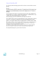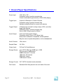
1
The Dream Player MK2
User Manual
Dream Player MK2 User Manual
Version 1.0
Copyright ©2012 PRICOM Design
Table Of Contents
1
2
Overview .................................................................................... 2
Using the Dream Player MK2 ................................................... 3
2.1
2.2
2.3
2.4
2.5
2.6
2.7
2.8
2.9
2.10
2.11
3
Connections ............................................................................... 7
3.1
3.2
3.3
3.4
3.5
3.6
4
Page 1
Updating Your Firmware ................................................................................... 23
Downloading the Firmware Update ................................................................... 23
How to Update Your Firmware .......................................................................... 23
Problems & Support ................................................................ 24
6.1
6.2
6.3
7
General Mode Setup ........................................................................................... 19
Trigger Input Configuration ............................................................................... 20
Control Output Setup ......................................................................................... 21
Audio Mode Configuration ................................................................................ 22
Firmware Updates ................................................................... 23
5.1
5.2
5.3
6
Power Input .......................................................................................................... 7
Audio Output Connector ...................................................................................... 8
Trigger Input Terminal Strip ................................................................................ 9
Control Output Terminal Strip ........................................................................... 12
Mode Switches ................................................................................................... 14
Mounting Holes .................................................................................................. 16
Introducing the CONFIG.TXT File ......................................... 17
4.1
4.2
4.3
4.4
5
Power Indicator .................................................................................................... 3
Status Indicator ..................................................................................................... 3
PLAY Button........................................................................................................ 4
Trigger Input ........................................................................................................ 4
Audio Output ........................................................................................................ 4
Power Input .......................................................................................................... 4
Control Output...................................................................................................... 4
SD Card and Socket ............................................................................................. 5
Mode Switches ..................................................................................................... 5
Creating WAV Files ......................................................................................... 5
Loading the SD Card ........................................................................................ 6
Help, I broke it! .................................................................................................. 24
E-mail ................................................................................................................. 24
Web Site ............................................................................................................. 24
Dream Player Specifications ................................................... 25
Dream Player MK2 – User Manual
Using your Dream Player MK2
1 Overview
Congratulations!
You have just received an extraordinary little device.
The Dream Player MK2 is packed full with an extensive array of features and measuring
only 3 ½ by 3 ½ inches, this is truly the best item of its kind.
Your sound files are stored on a microSD Card readily available at any electronics store
as well as through PRICOM Design. We have tested sizes ranging from 512MB-16GB
from a variety of manufactures and have success with them all. This means you could
have 25 hours of CD quality music playing in your project using a 16GB SD Card.
Also by using a microSD Card you are able to mount the board to anything and
anywhere, and easily change out or update the sounds that the device plays.
What about quality? The MK2 supports exceptionally high quality 44.1 KHz, stereo,
16bit, WAV Files.
You may also control the MK2 via external controls such as a button or motion sensor,
and also control Output devices such as LED‟s with it.
Another exiting feature of the Dream Player MK2 is the “CONFIG.TXT” file that is
stored on the SD Card. With this file you may change the characteristics of the Player.
Things such as how long a fade out can be? Should it be 5 seconds? 1 second? None at
all? Would you like the sound file to play only while you hold a button? How about
starting the track when the button is released and stop playing when pressed again? These
are just a handful of configuration combinations that you may have, and the beauty of it
all is that you may change it at anytime and to your exact situation.
Included with the Dream Player packaging is a CD containing sample Audio Files, a
sample CONFIG.TXT File, the complete User‟s Manual, and several other items to make
your experience as enjoyable as possible.
So read within to learn about the many exciting features of The Dream Player Mk2.
PRICOM Design
Page 2
Using your Dream PlayerMK2
2 Using the Dream Player MK2
The following pages describe the Configuration and operation of the Dream Player. You
can keep it as simple, or make it as complicated as you wish. With so many options and
Configurations available to you, the possible uses are endless.
2.1 Power Indicator
This LED will be lit whenever there is power supplied to the Power Input terminals. The
LED is also used to indicate the status of firmware updates as discussed later in on in this
manual.
2.2 Status Indicator
This LED will be lit when the Dream Player is currently playing an Audio Track or busy
reading the SD Card. If there is any trouble loading the SD Card, or a bad WAV file was
encountered this indicator will flash.
Page 3
Dream Player MK2 – User Manual
Using your Dream Player MK2
Upon power up, when you insert an SD Card into the SD Card Socket the status indicator
will blink once for every file on the SD Card then turn off. If you push the PLAY button
while the SD Card is initializing, the Dream Player will begin playing the first audio track
once the initialization is complete.
The status indicator will also rapidly blink when a firmware update is in progress, as
described later.
2.3 PLAY Button
To play the first Track on the SD card at any time, you can simply hit the PLAY button.
If you press the PLAY button when the Dream Player is already playing, the sound will
fade out and stop, or whatever the settings on the CONFIG.TXT file may be set for.
2.4 Trigger Input
This input is the way to control the activities of the Dream Player. In its factory state,
when the Dream Player is idle, the trigger input will cause the track to play. While the
Dream Player is playing a track, any kind of trigger input will cause the current track to
fade out.
Now any of the above mentioned scenarios may be customized using the CONFIG.TXT
file as described latter in this manual.
2.5 Audio Output
Audio is supplied by the Dream Player by means of a standard 1/8 inch stereo jack. You
may use any standard powered computer speakers as described in the next section. You
can also directly drive non-powered speakers, i.e. headphones, but the volume may be
fairly low. It is advisable that an Amplifier be used if you are using the Dream Player
with non-powered speakers.
2.6 Power Input
The MK2 may be supplied with AC or DC power ranging from 7-24 Volts and will draw
about 100ma when playing. The polarity actually is irrelevant on this board, you may
hook up the wires in either way and the device will still power on.
2.7 Control Output
As its name implies, you may use this function on the Dream Player to control up to four
outputs such as LED‟s, Relays, etc… The outputs will activate relative to their track
number/trigger number, but there is plenty more to learn about this feature in section 3.4.
PRICOM Design
Page 4
Using your Dream PlayerMK2
2.8 SD Card and Socket
Your Audio content, CONFIG.TXT File, and any firmware updates are loaded onto a
micro SD FLASH Card, and then inserted into the SD Card Socket. The connector used
on the Dream Players is unique in that the card is loaded from the top and not from the
front like standard connectors. One major feature of this style is that it ensures that the
card does not accidently fall out when the device is mounted.
To load the card into the connector, simply insert the card into the socket from the top
and while pushing down with your finger, pull towards yourself, you will feel when it is
secure. If the card is not properly fitted into the socket, it will actually pop back up, the
only the time the card remain down is when it is correctly inserted into the connector.
2.9 Mode Switches
If you do not have access to a computer or do not have the time to change the
CONFIG.TXT file then you may set the characteristics of the Dream Player by setting the
mode switches. Whatever you set on these switches will override anything on the
CONFIG.TXT File. To use the settings on the CONFIG.TXT file then leave all of the
switches in the off position.
2.10
Creating WAV Files
Any suitable sound editor can be used to create WAV files. The Dream Player will play
Stereo, 16-bit samples, at a 44.1KHz sample rate. This is the same format used for CD
Players and is quite standard.
Note: The Dream Player can NOT play MP3 files or other non-wav files.
Please visit the PRICOM Design web site (www.pricom.com), for some ideas and tips on
creating your own WAV Files.
We recommend numbering your files once you load them onto the SD Card. The Dream
Player will understand the numbers „1‟, „2‟, „3‟, or „4‟ when placed in front of the file
name. These numbers indicate to the Dream Player what „track‟ they are. If you do not
number the files, then the oldest file written to the card will be considered track 1.
You can name your files anything you want. For your convenience, you can name the
files something sensible like “Mountain Day.wav” on your computer, and then rename
the file once it is on the SD Card. A good file name is something like “1-Mountain
Day.wav” which would be treated as Track-1.
During normal operation the Dream Player will play track 1 by default when the on-board
button is pressed or is triggered from an outside source via the trigger input.
Page 5
Dream Player MK2 – User Manual
Using your Dream Player MK2
2.11
Loading the SD Card
In order for the Dream Player to read the files, they must be copied onto the mirco SD
Card. Any standard SD Card reader attached to any computer can be used. The Dream
Player will accept any brand of SD Card, in any capacity up to 16GB.
Simply copy your wav files onto the micro SD Card. The Dream Player will not look in
any folders or sub-directories for its files. After you copy files onto the SD Card, a file
may be renamed at any time. The MK2 will accept fragmented cards, meaning you do not
have to delete all files off the card before loading your news ones on. For example if you
had 4 tracks on your card and you wanted to change track 2 you can simply delete the old
track and put the new one on the card, without having to delete and then rewrite ALL the
files.
PRICOM Design
Page 6
Using your Dream PlayerMK2
3 Connections
The following section provides detailed instructions for connecting your Dream Player
MK2. To get started quickly, all you need to do is connect the Power Input, and the
Audio Output. Then when you are ready, you can get more advanced and use the Trigger
Inputs and Control Outputs.
3.1 Power Input
The Dream Player can accept AC or DC power inputs.
Typically a wall transformer, or wall-wart is used, but any
suitable AC or DC power supply can be used. Any voltage
from 7V to 24V AC or DC can be used, but the higher the
voltage, the warmer the Dream Player will run. The most
efficient voltage to use is 9VDC. At this voltage, the Dream
Player will draw about 120MAwhen playing, so use a power
supply that can supply 200MA or more of current. If you wish
to power multiple Dream Players, a single larger power
supply can be used, just allow for 200MA for each Dream
Player you wish to power. As a convenience to you, we also
offer wall-transformer power supplies tested and ready to run
with your Dream Player at www.pricom.com
The power source used can be shared with other devices, but
be careful as the Audio Ground will be referenced to this
power source. If you observe a buzzing or other interference
noise, it would be best to give your Dream Player its own
power supply.
To connect the power supply to the Dream Player, locate the
2-position “Power Input” terminal strip.
If your desired power-supply comes with a connector on the
end, simply clip it off as shown to the right. Separate the two
wires and strip some insulation off to expose the actual wires
then twist them to keep the strands together. Secure the
stripped wire ends to the 2 terminals of the Power Input
terminal strip. The polarity of an AC or DC power source is
not important as there is a bridge rectifier included with the
Dream Player.
Page 7
Dream Player MK2 – User Manual
Using your Dream Player MK2
3.2 Audio Output Connector
The Dream Player can drive any audio amplifier, powered speakers, or media speakers
that are typically used on a computer. A very nifty feature of The Dream Player LITE is
that it can directly drive non-powered or conventional speakers without an amplifier,
headphones or ear buds for example.
Prices of media speakers are quite reasonable and you may obtain then from practically
every computer store and electronic outlet. Depending on the quality and volume you are
trying to achieve, these speakers can be
purchased anywhere from $15-$50, or as
high as $100+. We have found that
many of the $35-$50 speakers sound
terrific for any application and meet
most of our customer‟s needs just fine,
and some of them are quite small and
easy to conceal. Choose your speakers
wisely as the best audio you can get is
often times limited by the quality of the
speakers you choose. If you are at a loss
for what speakers to get, we offer some
reviews of speakers we have purchased
on-line with some links to how you may
purchase them. Please visit
www.pricom.com
To connect the speakers to the Dream
Player, you simply plug-in the stereo plug
from the speakers into the Audio Output
jack on the Dream Player. You can insert
as many extensions as needed to
accomplish your wiring. These extensions
are 1/8” stereo cables, and sometimes are
sold as headphone extension cables.
Again many electronic stores will sell this
item.
To avoid „blowing something up‟ set the volume on the speakers‟ pretty low to start with,
and then adjust as appropriate for your sounds and speaker setup. All sounds are clearly
not created and mixed on equal levels, and we would hate for you for blow a good set of
speakers after start-up. To state the obvious, start low and work your way up from there.
PRICOM Design
Page 8
Using your Dream PlayerMK2
3.3 Trigger Input Terminal Strip
More than simply playing a sound file, your Dream Player is capable of acting and
reacting based on input from you or the devices it is controlling. This section describes
the electrical connections for the Trigger Inputs. Section-3 entitled “Using the Dream
Player” describes the operational functions and events that are controlled by the Trigger
Inputs.
The Trigger Inputs of the Dream Player are optically isolated which means you can wire
the inputs so that they are electrically isolated from the Dream Player. Why is that
important? Because sharing a common ground between an Audio Playback system and
any other system can, and usually does, create ground loops and noises such as „buzz‟
and „hum‟. By isolating the Trigger Inputs, we have removed this problem for you!
As a convenience to your wiring, you may use the power supplied on the Trigger Input
Terminal Strip, but doing so will defeat the isolation offered by the Dream Player. If you
are simply wiring switches or buttons, there isn‟t much chance of a „ground loop‟ or
„noise‟, so we give you the best of both worlds.
Figure 1 – Trigger Input Terminal Strip Pinout (P4)
Terminal
1
2
3
4
5
6
7
Name
GND
Trigger-1
Trigger-2
Trigger-3
Trigger-4
POS
5V
Description
Convenience power supply ground
Opto-Isolated Trigger #1 Input
Opto-Isolated Trigger #2 Input
Opto-Isolated Trigger #3 Input
Opto-Isolated Trigger #4 Input
Opto-Isolator Shared Power Input
Convenience power supply (5VDC)
The trigger input terminals (Trigger-1 to Trigger-4) provide connection to the low-side
(Cathode) of the LED in each opto-isolator. Current limiting resistors are built-in, so you
can simply connect any Trigger Input to GND to cause the Trigger to occur.
Terminal #6 (POS) is connected to the high-side (Anode) of all 4 opto-isolators.
Typically Terminal #6 is connected to the power source to be used to trigger the inputs.
This can be an external power source or Terminal #7 (5V), if you do not need to isolate
the Dream Player ground. The internal current limit resistors are suitable for voltages
from 5VDC up to 24VDC. If higher voltages are required please contact us to determine
suitable added current limit resistors.
Terminal #1 and Terminal #7 provide a local power source that is not isolated from the
Dream Player, but can be used to simplify wiring if just using push-buttons, relays, or
other input that doesn‟t require optical isolation.
Page 9
Dream Player MK2 – User Manual
Using your Dream Player MK2
The following example shows how to connect switches (or relays for that matter) directly
to the Dream Player without utilizing the ground isolation features of the opto-isolators.
The convenience 5VDC power supply from the Dream Player is jumped to the optoisolator POS terminal to supply the shared LED Anodes. Each Trigger Input can then be
individually connected to the convenience GND pin though any suitable switching device
such as a push-button or relay.
Figure 2 - Simple Trigger Input Button Connections
Note: The actual function of each Trigger Input is determined by DIP Switch settings.
More detailed application information is located in Section-3 of this manual.
In the next example, we will use an external power supply to enable the opto-isolators to
completely isolate the Dream Player Ground from the controlling device. Notice that the
POS terminal is used, but not the 5V or G terminals. Opto-isolator power is supplied
from the external 4-24VDC Power Supply.
Figure 3 - Isolated Trigger Input Button Connections
PRICOM Design
Page 10
Using your Dream PlayerMK2
The switch examples shown above don‟t really need the opto-isolators, so where would
you need the opto-isolators? How about connecting to a DCC Decoder!
In the next example, we will connect a Digitrax TF4 to allow the Dream Player to be
controlled directly from your DCC System. Any brand of mobile or stationary decoder
could be used, but the low-cost of the TF4 lends itself nicely to this application.
Here we have connected the 4 function outputs of the TF4 to the 4 Dream Player Trigger
Inputs. Since the DCC Decoder must be connected to the DCC System, where there is
considerable noise, some kind of isolation would really help us here. The Dream Player
opto-isolators keep the DCC system completely isolated from the Audio Ground and
remove any chance of noise entering the sound system and speakers. Note that the 5V
and the G terminals are left un-connected since the opto-isolators are being powered from
the DCC decoder lamp power lead.
Figure 4 - Isolated DCC Decoder Connections
.
Note: The actual function of each Trigger Input is determined by the on-board DIP
Switch settings or using the CONFIG.TXT File.
Page 11
Dream Player MK2 – User Manual
Using your Dream Player MK2
3.4 Control Output Terminal Strip
The Dream Player is capable of controlling many types of devices and loads connected to
the Control Outputs. This section describes the electrical connections for the Control
Outputs.
The Control Outputs of the Dream Player are not isolated in any way from the Audio
Ground of the Dream Player. Why is that important? Because sharing a common ground
between an Audio Playback system and any other system can, and usually does, create
ground loops and noises such as „buzz‟ and „hum‟. If grounding problems become an
issue for your application, an external relay can be used to isolate the load from the
Dream Player.
As a convenience to your wiring, you may use the power supplied on the Control Output
Terminal Strip, but doing so will draw power from the internal 5V regulated supply used
to power the Dream Player. Use this convenience power for LED‟s, small relays, or
triggering another Dream Player, but if you intend to power any larger loads, please
consider an external power source for the Control Outputs.
Figure 5 – Control Output Terminal Strip Pinout (P6)
Terminal
1
2
3
4
5
6
7
Name
GND
Output-1
Output-2
Output-3
Output-4
Clamp
5V
Description
Convenience power supply ground
Control Output #1
Control Output #2
Control Output #3
Control Output #4
Common Clamp Diode Connection
Convenience power supply (5VDC)
The control output terminals (Output-1 to Output-4) provide connection to a Darlington
Transistor Array (Collector) used to Sink Power, but can not Supply Power. Each Output
is capable of sinking 400MA using the ULN2803 in the socket at U7. The Darlington
Array has its Emitters connected to the GND Terminal #1. External or Convenience
power can be used to power the load, but the reference and current ground will be using
GND Terminal #1.
Terminal #6 (Clamp) is connected to the Darlington Array protection diodes (Cathode)
for all 4 outputs. If you are driving an inductive load such as a relay, the Clamp terminal
should be connected to the power source being used for the load. This Clamp Terminal
will prevent the back-lash of the relay from destroying the Darlington Array. If simply
driving LED‟s this terminal can be left un-connected.
Terminal #7 provides a local power source that is not isolated from the Dream Player, but
can be used to simplify wiring if just powering LED‟s or other small loads. Power used
from this terminal can cause the on-board voltage regulator to become hot under load.
PRICOM Design
Page 12
Using your Dream PlayerMK2
The following example shows a simple way to connect status LED‟s to the Dream Player
using the convenience 5VDC power supply. The LED‟s will require current-limiting
resistors since each Control Output can sink 400MA and would burn-out the LED‟s.
Since the LED‟s do not present an inductive load, the Clamp terminal has been left unconnected.
Figure 6 - Simple Control Output LED Connections
Note: The function of each Control Output is determined by the on-board DIP Switch, or
the CONFIG.TXT File. See the information contained in this manual about
functionality
The Dream Player can also be used to drive conventional DC powered lamps or DC
powered relays. Using external relays allow much higher power to be controlled, or even
AC Line voltage. The possibilities are endless, but the next example shows how to
connect external lamps or relays using an external power source.
The external power source is used for this example so that not too much power is
consumed from the Dream Player‟s on-board 5VDC power supply regulator. If the relays
are high-efficiency and can be powered from 5VDC, then the on-board 5VDC power
source could be used. In the following example, we are using an external power source.
Page 13
Dream Player MK2 – User Manual
Using your Dream Player MK2
Figure 7 - Lamp/Relay Control Output Connections
The common lamp/relay connection must be to the Positive terminal of the power supply,
and also is connected to the Clamp terminal to utilize the Dream Player‟s built-in
protection diodes. The external power supply Negative terminal is connected to the GND
Control Output terminal. This arrangement causes the positive voltage to flow though the
lamp/relay, into the Control Output terminal, and back out the G Control terminal, and
complete the circuit at the power supply negative terminal.
Because the Dream Player uses a Darlington Transistor array for the output control
switching element, AC power cannot be used, only DC is possible.
3.5 Mode Switches
The Dream Player has many options available for the Trigger Inputs, Control Outputs,
and other functions. These features may be tailored to your specific situation using the
CONFIG.TXT file which we will cover later on. However most of these options may also
be set using the onboard Mode DIP Switches. Whatever is set on the DIP switch will take
priority over whatever is set on the CONFIG.TXT file. If all the switches are in the
down/off position then the Dream Player will use whatever settings are in the
CONFIG.TXT file.
PRICOM Design
Page 14
Using your Dream PlayerMK2
Figure 8 - Mode Switch Settings
Switch 1 – Loop Mode
The selected audio track will play continuously over and over until
ON
another Trigger Input is detected or the PLAY button is pressed
OFF The audio tracks will play once only and stop when the end is reached
Switch 2 – Random Mode
A trigger will cause a random track to be selected and played. The random
ON
track will play once or loop forever depending on the setting of Switch 1 –
Loop Mode
OFF Random track selection is not enabled
Note: When Random Mode and Loop Mode are both ON, Trigger #1 will pick a new
random track with each playback loop. Trigger #2 will pick a random track and
continue to loop that single random track.
Switch 3 – Loop While Trigger
The selected audio track will continue to loop and play as long as the
ON
respective trigger input is present. Once the trigger is removed, the current
track is played to completion then the Dream Player will stop
OFF Loop while trigger is not enabled
Note: Loop While Trigger can also be combined with the Random Play Mode to
cause random tracks to be played as long as the Trigger is present.
Switch 4 – Spare
ON
Not used yet
OFF Not used yet
Page 15
Dream Player MK2 – User Manual
Using your Dream Player MK2
Switch 5
Switch 6
ON
ON
ON
OFF
OFF
ON
OFF
OFF
Control Outputs
This mode selection is not used yet
At the END of each track, the respective
Control Output will momentarily go active
or pulse
At the BEGINNING of each track, the
respective Control Output will
momentarily go active or pulse
During PLAY of each track, the respective
Control Output will constantly be held
active
Switch 7 – Spare
ON
Not used yet
OFF Not used yet
Switch 8 – Auto Start
When power is applied to the Dream Player, playback of Track #1 will
ON
automatically begin playing after about 2 seconds
OFF Playback will NOT automatically start at power-on
All switch modes can be combined in any manner. For example, a useful setup would be
combining Auto Start Mode, Random Mode, and Loop Mode. This would cause the
Dream Player to start playing a random track after power-up, when the track ends, pick
another random track and play. This process would continue until a trigger input is
detected or the PLAY button is pressed.
3.6 Mounting Holes
The Dream Player can be mounted to any non-conducting surface using the supplied
mounting holes. Although there are not any components on the back of the LITE, using
some form of stand-off would be advisable to keep from breaking anything and more
importantly avoid any unwanted short circuits. The mounting holes are electrically
isolated however, and using steel screws is fine, but please do be careful not to over
tighten them.
PRICOM Design
Page 16
Using your Dream PlayerMK2
4 Introducing the CONFIG.TXT File
Upon first glance the CONFIG.TXT file looks intimidating but is pretty self explanatory,
and easy to use. The below screen is as it appears directly off a PRICOM Design supplied
microSD Card, downloaded off our website, or from the included CD.
If for some reason you neglect to put the CONFIG.TXT file onto your SD Card this is the
standard CONFIG.TXT that the MK2 would revert to.
Page 17
Dream Player MK2 – User Manual
Using your Dream Player MK2
We will just go ahead and simply go down the list of what we can do with this awesome
little file.
First off;
To make a Function ACTIVE, remove the “#” from in front of it. If a feature is not
applicable to your situation and you do not need it, simply insert a “#” in front of
the name.
You may name the file whatever you want just so long as it starts with “CONFIG.TXT”
and ends with .txt. For example “CONFIG.TXT-bobsstuff.txt”, “CONFIG.TXT.txt” and
“CONFIG.TXT-thisismysampletestfile.txt” would all work.
There should only ever be one CONFIG.TXT file on the mirco SD Card.
This CONFIG.TXT File must be less than 4KB long. We have a limited about of memory
space that we can dedicate to reading this specific file and 4KB happened to be that
number. In its original condition and as it is displayed above it measures about 3.01KB.
But the above includes a lot of text and to make the file do its job you should not have to
mess with the text at all. So space should not be too much of an issue. Just don‟t go
writing any excessively long comments to yourself.
Overall the nice thing is that if for some reason you forget what a particular function
does, the description is found in the file and will pretty much just explain itself.
So enough housekeeping let‟s get into what each one does.
PRICOM Design
Page 18
Using your Dream PlayerMK2
4.1 General Mode Setup
Feature
Auto Start
Loop Mode
Random Mode:
Multi Random:
Background Mode:
Description
The file will begin to play automatically as soon as the power is
applied to the device.
Will continuously loop the sound until an outside trigger stops it (a
button for example).
Will randomly select from up to 4 files on the SD card. The player will
only play the selected file once, unless this mode is combined with
Loop Mode.
You may have up to four files per track, and the Dream Player will
randomly play from these four. For example, if you have this feature
enabled and you trigger track one it will play randomly from the four
track ones. This effectively enables you to have up to sixteen tracks on
a Dream Player.
In addition to the normal pre file numbering 1-,2-3-,4-. You may have
a track “0-” that acts as a “background” track. When you use this
feature, the Dream Player will continuously play the 0- track until a
trigger is activated. The Player will then play that file until the end and
resume the background track.
If you want your device to start playing while continuously looping 4 randomly selected
tracks as soon you apply power, your file would look like this.
Page 19
Dream Player MK2 – User Manual
Using your Dream Player MK2
4.2 Trigger Input Configuration
Feature
Loop While Trigger
High Trigger
NO Retrigger
Toggle Trigger
Description
Just as its name implies this feature will make the Dream Player
continue to loop the file and play it over and over so long as the
button/input is active. If you are using a button as your input, then if
you press and hold the button the file will play continuously. Release
the button and the file will play to the end and then stop.
Instead of playing the file when the trigger input is closed, this reverses
the trigger logic so that it plays when open. With a button as an
example of input then the file will play when the button is released
“open” and then stop playback when you press the button “closed”.
This is a great option for motion detectors.
Once a file is playing the trigger input is ignored until the file has
completed playing. Also great for motion detectors.*
Using the toggle trigger feature allows you to switch between two files
on the same device. Switching between a Daytime track and a
nighttime track is a good example. This is done by using a switch
connected to the trigger input. Now it has to be a switch, a button
(momentary contact) will not work.
*This would be perfect if you put the Dream Player in a high traffic area where people
may be pushing the button quite often and complete playback of the audio track is
desired. With this feature you may elect to have the Dream Player ignore all outside
triggers until the track finishes. This means you could have a thousand people walk by
and push the button but the sound will continue to play for the person that initially played
that track regardless of what people ask of it.
PRICOM Design
Page 20
Using your Dream PlayerMK2
4.3 Control Output Setup
You may want to control some LED‟s, motors, or some other form of “action” items. In
this section of the CONFIG.TXT file you may select whether you want the output item to
be active as long as the file is playing or only at the beginning or end of the track.
Feature
Control Begin
Control End
Control Play
Control Pulse Time
Page 21
Description
When the track starts playing and you have this feature enabled, the
output device will be active for the specified amount of time as defined
in the later CONFIG.TXT file then stop for the remainder of the track.
Just the opposite of the Control Begin (funny how that works). That
means that the output device will become active for the specified
amount of time after the file plays.
The control output will simply stay active as long as the file is playing.
You may define exactly how long the output is active. Times are
defined in Milliseconds and if our math is right 1000MS amounts to 1
full second, you can actually set your output to pulse for just 1MS.
Doubtful it will be of any interest flashing an LED for 1MS, but maybe
one of you has the application that requires such a rapid output. If both
Control Begin and End features are disabled then the pulse time is not
used
Dream Player MK2 – User Manual
Using your Dream Player MK2
4.4 Audio Mode Configuration
The last category is the audio output preferences. This section allows you to make a few
simple adjustments to adapt the MK2 to your specific situation. Your project may require
a quicker fade than the default settings or maybe you need instant stoppage of playback,
and what if the output seems too loud? You may change the settings here to suite your
needs very specifically.
Feature
Master Volume
No Fade
Fade Time
Description
The output volume of the Dream Player may be adjusted to your
situation. For example if you have a set of speakers in your project but
cannot access the volume on the physical speaker you may adjust the
volume that the Dream Player produces.
One of the most self explanatory features in the file. If you want the
Dream Player to fade, leave this feature disabled with a “#” in front of
it. If you want the audio to instantly stop instead of fading then activate
the feature.
A neat feature of this CONFIG.TXT file is that you may customize the
fade time exactly to the millisecond that you need. You may use
anything from 1MS to 65000MS. If you have No Fade enabled then the
fade time is irrelevant.
PRICOM Design
Page 22
Using your Dream Player MK2
5 Firmware Updates
5.1 Updating Your Firmware
One very special feature of the Dream Player is the convenience of updating firmware, no
cables needed. Revisions of firmware are loaded onto the micro SD Card which allows
you to load any critical updates to the firmware without having to totally dismantle your
project to get the unit to your computer.
5.2 Downloading the Firmware Update
When firmware updates become available we will announce it on our website
www.pricom.com. On the download‟s page find the updated version of firmware and
click the download link.
The firmware updates are a special PRICOM Design file called PDI, which means your
machine will most likely not recognize the format and so you will be prompted with a
box asking if you want to Find, Save, or Cancel.
You will want to SAVE the file, and to a folder somewhere that makes sense and you can
find it, “PRICOM Downloads” would be a good example.
After you save the file to your machine you may simply load it onto your micro SD Card.
5.3 How to Update Your Firmware
To initiate the firmware update process just follow the steps below.
1. Power off the Dream Player.
2. Remove the mirco SD Card.
3. Load the Card into your computer.
4. Copy the PDI File onto the card.
5. Insert the card back into its position on the Dream Player.
6. (important) Hold down the onboard button while reapplying power.
7. Reapply power to the Dream Player.
8. The two LED‟s will flash four times to indicate the unit is in update mode.
9. You may stop holding down the button at this point.
10. The Red LED will rapidly strobe while the update is taking place.
11. Generally the update takes only a few seconds and upon completion of the update
the LED will stop flashing, and you are ready to go.
Note: Remember to hold down the button when reapplying power to the unit.
Otherwise the Dream Player will not look for the Firmware.
Page 23
Dream Player MK2 – User Manual
Section 6 – Problems & Support
6 Problems & Support
Our goal is a product that is robust and trouble-free for you, however in the real-world,
problems unfortunately do arise.
6.1 Help, I broke it!
If you are not happy, then we are not happy! If you have a mishap with your Dream
Player, please let us know. Contact us at the e-mail below if you have questions or
problems. Generally the problems end up being simple fixes that can be diagnosed and
repaired by you the user with help from us here.
6.2 E-mail
If you are experiencing trouble with your Dream Player, please let us know. We are here
to help you, and want your experience to be creative and fun. If you need help of any
kind, please contact us via e-mail. The support e-mail address is [email protected].
6.3 Web Site
The PRICOM web site is where we will post any upgrades, updates, and improvements.
Please be sure to check for Hardware and Software updates. www.pricom.com
PRICOM Design
Page 24
7 Dream Player Specifications
7-24V AC or DC
Connection using 2 position terminal strip
Current consumption approximately 120mA while playing
Trigger Input:
4 Inputs for Switches or Contact Closures
Connection using 2 position terminal strip
Optically isolated with built-in current limit resistors
Trigger Output:
4 Outputs may be used for relays, lamps, LEDs, and other
trigger able devices.
Connection using 7 position terminal strip
Pulls to GND. Output rated for 200mA
Audio Output:
Line Level Analog Audio Output
Connection using 3.5mm (1/8”) Stereo Jack
Allows direct connection of amplified ‘media speakers’
May also use non-powered speakers, such as headphones
Audio Formats:
16bit, stereo
Sample Rates:
44.1KHz
Output Level:
3V Peak-To-Peak Maximum
Storage Device:
micro SD FLASH Card 64MB up to 16GB
Files use about 10MB/minute.
64MB holds about 7 minutes
1GB about 100 minuets
2GB about 3 hours
16GB about 25 hours
Storage Format:
FAT, FAT32 formatted cards (standard)
File Format:
Standard WAV files placed in the root folder of the card
Page 25
Power Input:
Dream Player MK2 – User Manual
Dream Player MK2 User Manual
Version 1.0
Copyright ©2012 PRICOM Design