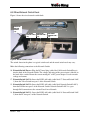
1
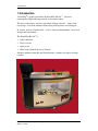
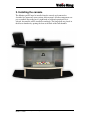
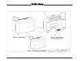
™
Bel Air Installation,
Set up, and
Configuration Manual
October 1, 2009
Document history
Date
Prepared by
Description
October 5, 2007
Holly Steele
Made the following changes:
• Updated manual to include new cable
labels
• Updated sections 1, 6, 8, and 9
• Added the hardlock to the wiring
diagram (section 13)
• Included the cable label matrix (section
12)
• Reformatted the document to make it
easier to read and navigate
April 9, 2008
Terry Lowdon
•
Updated the part number for the
Pyramid Display.
Oct 28, 2008
Gord Boyechko
•
•
UL AC cord Warning
Series 11 PC connections
Oct 30, 2008
Gord Boyechko
•
UL AC Receptacle Notice
Apr 30, 2009
Gord Boyechko
•
Cable labels
Jun 24, 2009
Gord Boyechko
•
•
Ball rail brackets
Service address
Sept 4, 2009
Gord Boyechko
•
Ball chamber material
Oct 1, 2009
Gord Boyechko
•
Replace motor instructions
Bel Air™ Installation, Set up, and Configuration Manual
October 1, 2009
i
Important Notice
This guide is delivered subject to the following conditions and restrictions:
This guide contains proprietary information belonging to Video King. Such
information is supplied solely for the purpose of assisting explicitly and properly
authorized users of the Bel Air™ system.
•
•
•
•
•
No part of its contents may be used for any other purpose, disclosed to any
person or firm or reproduced by any means, electronic or mechanical,
without the express prior written permission of Video King.
The text and graphics are for the purpose of illustration and reference
only. Specifications on which they are based are subject to change without
notice.
The software described in this document is furnished under a license. The
software may be used or copied only in accordance with the terms of that
agreement.
Information in this document is subject to change without notice.
Corporate and individual names and data used in examples herein are
fictitious unless otherwise noted.
The use of masculine gender terms is to be interpreted as being nongender specific and is used solely to minimize textual complexity.
Copyright © 2007 Video King
Bel Air, PowerServer, PowerEdit, PowerPlay, PowerTouch, Super Champ and
Lil’ Champ are trademarks of Video King. All other product names are
trademarks or registered trademarks of their respective owners, and are hereby
acknowledged.
*** WARNING ***
AC Cord replacement – if the cord is damaged it must be replaced by a cord or
assembly from the manufacturer.
*** IMPORTANT ***
IO box and PC AC cords must be plugged into its own sock outlet. A duplex
receptacle is acceptable.”
Bel Air™ Installation, Set up, and Configuration Manual
October 1, 2009
i
Table of Contents
1 Introduction .................................................................................................................... 1
2. Unpacking the console................................................................................................. 4
3. Installing the console ................................................................................................... 5
4. Electrical installation .................................................................................................... 6
5. Layout of the devices and controls............................................................................. 7
6. Connector layouts......................................................................................................... 8
Figure 3: Series 11 PC back......................................................................................... 8
6.1 Computer Back ....................................................................................................... 9
6.2 Monitor External Cables ....................................................................................... 11
6.3 Monitor Internal Cables ........................................................................................ 12
6.4 PC Video In Cable ................................................................................................ 13
6.5 PC Video Out Cable ............................................................................................. 14
6.6 Wired Video Switch Back ..................................................................................... 15
6.7 Video Switch Front ............................................................................................... 16
6.8 Wired Network Switch Back ................................................................................. 17
6.9 I/O Box Front ........................................................................................................ 18
6.10 I/O Box External Cables ..................................................................................... 20
6.11 Wired IO Box Back ............................................................................................. 22
6.12 Ball Camera........................................................................................................ 24
7. Operating the Bel Air .................................................................................................. 25
8. Servicing and cleaning ............................................................................................... 26
9. Troubleshooting.......................................................................................................... 27
10. Warranty..................................................................................................................... 28
11. Service ....................................................................................................................... 30
12. Cable label matrix ..................................................................................................... 31
13. Wiring diagram .......................................................................................................... 32
14. Technical Specifications .......................................................................................... 33
Appendix: Exploded assembly drawings and bill of material .................................... 35
Appendix: Motor Replacement ...................................................................................... 55
Bel Air™ Installation, Set up, and Configuration Manual
October 1, 2009
iii
1 Introduction
1 Introduction
Video King® is proud to introduce the PowerPlay Bel Air™ —the most
contemporary, high-tech bingo console on the market today!
The wave of the future, our latest generation of bingo consoles – with a sleek,
new design – has all the ultimate features bingo hall operators are looking for.
In essence, the best of both worlds – as far as form and functionality – have been
merged and transformed …
The PowerPlay Bel Air™ is
•
Softly contoured
•
Easy to service
•
Quiet to run
•
Fully loaded with all the latest software.
All these attributes make Bel Air North America’s number one choice in bingo
consoles.
Bel Air™ Installation, Set up, and Configuration Manual
October 1, 2009
1
1 Introduction
Standard Features:
• Touch screen, flat-panel monitor with built-in speakers.
•
Slant-top design for caller comfort.
•
PC technology. Windows XP Operating System.
•
Removable front and side panels for easy maintenance.
•
Removable motor and base for easy maintenance.
•
NTSC camera for live ball image.
•
Secure cabinet design with lockable panels.
•
Software Controlled Video Switch for enhanced multi-media control.
Software Features:
• Compatible with e-BOS™ gaming systems, including Video King’s
PowerTouch fixed-base systems, Champion II gaming tablet, and full line of
handheld bingo devices.
•
Compatible with Bingo Racing software.
•
Supports PowerVideo software, for multimedia flashboard displays.
•
Integrated presentation software for “in-hall” advertising.
•
Advanced Windows-based PowerEdit game program editor.
•
Digital image picture-in-picture for live ball display on the game screen.
•
Easy-to-follow, on-screen directions and menus.
•
Easy back-up of game programs.
•
Remote access software for program changes/troubleshooting.
•
Full “system-restore” software.
•
Built-in verification of all known bingo perms.
•
Supports complex pattern definitions, including multi-level, multi-card
patterns.
Optional Features:
• Multi-year extended warranty.
•
“A” Data signal translator for connection to “A” Data style flashboards.
•
Can be configured for right-handed or left-handed callers.
2
Bel Air™ Installation, Set up, and Configuration Manual
October 1, 2009
Note
This manual covers many aspects of the Bel Air™ bingo console with the
exception of the software. It covers unpacking, installation, set up and servicing
of the console. For operation of the bingo console and e-BOS™ software, please
see our PowerPlay™ User’s manual and e-BOS™ Utilities User’s Manual.
Bel Air™ Installation, Set up, and Configuration Manual
October 1, 2009
3
2. Unpacking the console
2. Unpacking the console
Inspect the shipping containers for possible signs of damage. If damage is
detected, call the carrier to make a claim.
Use a box cutter to cut the straps from the skid, taking care not to damage the
console. With the help of at least one assistant, carefully slide the console from
the skid and place it on the floor. Remove the cardboard top. Remove the foam
packing inserts from inside the top and slide the cardboard tube up and off the
console. A minimum of two people are required to safely unpack the console.
With one person lifting from each end of the console, raise the console up and out
from the carton and foam inserts. Check that all casters are in place. Do not
destroy or discard carton or packing material until after final inspection and
testing.
Unpack the keyboard from the cardboard box. Place the keyboard on the
electronics cabinet in front of the touch screen monitor. Remove the mouse from
the plastic bag and set next to the keyboard. At this point, you should inspect the
consoles for any obvious shipping damage. If any problems are found,
immediately contact your distributor for advice.
4
Bel Air™ Installation, Set up, and Configuration Manual
October 1, 2009
3. Installing the console
The Monitor and PC must be installed into the console and connected as
described in Connector Layout section of this manual. All other components are
pre-assembled. Depending on if a right hand or left hand operation desk is
ordered, the monitor will be installed accordingly. The bingo balls are placed in
the blower chamber by opening the door at the back of the ball chamber.
Bel Air™ Installation, Set up, and Configuration Manual
October 1, 2009
5
4. Electrical installation
4. Electrical installation
Plug the console AC power cord into a 115VAC, 60Hz.outlet
The main AC power input to the Bingo Console should be 115VAC, 60Hz. The
power outlet or power cord to the Bingo Console should be wired with 12AWG or
14AWG with ground. The AC power input circuit must be rated for at least 15A
and no other hall equipment should share this power source. Do not run long
extension cords with inadequate wire gauge from the power source to the console.
The main AC power input may be optionally plugged into an Uninterruptible
Power Supply ( UPS) to provide power backup in the event that main power is
lost. The desk and all its components have a typical maximum power draw of
850W with the blower motor running.
Caution! A power source with abnormal voltage or excessive noise can result
in improper console operation and possible damage not covered under
warranty.
6
Bel Air™ Installation, Set up, and Configuration Manual
October 1, 2009
5. Layout of the devices and controls
The following user accessible devices and controls are located on the desk:
•
Ball Camera and Ball Chute—located at top of desk.
•
Monitor and Touch Screen—located on left or right of desk top.
•
Ball Tray —located on top front of desk.
•
Ball Tray Release — top control directly below Ball Tray.
•
Ball Chamber Release —located directly below Ball Tray Release.
•
Ball Chamber Door —top door in middle back of desk.
•
Blower Motor Door —bottom door in middle back of desk.
•
Right Door —PC, Keyboard, and mouse access.
•
Left Door —Network Switch, Video Switch, and IO Box access.
•
Front Door —Access to wiring (must remove Left and Right doors first).
Bel Air™ Installation, Set up, and Configuration Manual
October 1, 2009
7
6. Connector layouts
6. Connector layouts
This section describes the connection between the major internal components
within the desk. The major interconnected components are the; Computer,
Monitor, Keyboard, Mouse, I/O Box, Video Switch, Network Switch, Ball
Camera, Master Panel (Ball Rail), Fluorescent Lamp, Blower Motor, and Power
Block.
See section 13 Wiring diagram, page 32 for a schematic diagram of major
component interconnects. See the section 12 Cable label matrix, page 31 for a list
of the cables and their label names and numbers.
The following sections show component connectors and connections.
Figure 3: Series 11 PC back
8
Bel Air™ Installation, Set up, and Configuration Manual
October 1, 2009
6.1 Computer Back
Figure 1 shows the connectors that you plug the devices into. Figure 2 shows the
back of a correctly wired computer. Figure 3 shows the series 11 PC back.
A
A
B
C
B
C
13
4
4
E
13
E
D
D
18
5
10
5
9
10
15
9
18
15
1
1
7
7
14
14
11
11
Figure 2: Wired computer back
Figure 1 Computer back
Legend
A. 120 VAC
7. PC I/O box (serial)
Important notes:
B. PS/2 keyboard
(purple)
9
The numbers refer to the cable labels.
C. PS/2 mouse (green)
D. Hardlock (USB)
E. Not used (VGA)
1. PC VGA (blue)
4.
PC Touch screen
(serial)
5. PC Audio Out (green)
PC Audio in (blue)
10 PC Mic in (red)
11 PC Modem (Line in)
13 PC Printer (LPT)
14 PC Video in (VGT)
15 PC Video out
(to hall monitors)
18 PC LAN
Bel Air™ Installation, Set up, and Configuration Manual
October 1, 2009
The letters refer to unlabeled devices
or cables.
If you want the audio to go to the
monitor speakers, plug in Monitor
Audio In (cable label 5 in Figure 2)
from the monitor to the back of the
computer (label 5 in Figure 1).
If you want the audio to go to the hall
PA system, plug in PC Audio Out PA
(label 8) from the I/O box to the back
of the computer (label 5 in Figure 1.
Cable label 8 is not shown in Figure 2
because cable label 5 is plugged in.
9
6. Connector layouts
The following interfaces require connection on the back of the computer. The numbers
correspond with the cable labels and the letters refer to the unlabeled cables.
A. 120 VAC—Connect the AC receptacle to the Power Block.
B. PS/2 Keyboard—Connect the PS/2 keyboard to this port. The connector is typically green.
C. PS/2 Mouse—Connect the PS/2 mouse to this port. The connector is typically purple.
D. Hardlock—Connect the USB hard lock it to a standard USB port. If you have a parallel hard
lock, connect it to a parallel port.
1. PC VGA—Connect the DB15P VGA connector (cable label 1 PC VGA) from the Monitor
into this connector.
4. PC Touch Screen—Plug the DB9 serial connector (cable label 4 PC Touch Screen) from the
Touch Screen Monitor into this connector.
5. Monitor Audio In—Plug the 1/8” stereo plug cable (cable label 5 Monitor Audio In) into
this connector. The connector is green.
7. PC IO Box Serial—Connect the I/O Box DB9P serial cable (cable label 7 PC IO Box Serial)
to this port.
9. PC Audio in—Plug the 1/8” stereo plug (cable label 9 PC Audio In) into this connector. The
connector input is blue.
10. PC Mic in—Plug the 1/8” stereo plug cable (cable label 10 PC Mic In) into this connector.
The connector input is red.
11. PC Modem –Connect the RJ11 plug (cable label 11 PC Modem) from the I/O Box into this
connector.
13. PC Printer—Connect the DB25P pass through printer cable (cable label 13 PC Printer) from
the I/O Box to this port.
14. PC Video in—Plug the RCA phono plug (cable label 14 PC Video In) from the Video
Switch into this connector.
15. PC Video out—Plug the S-Video cable (cable label 15 PC Video Out) from the Video
Switch into this connector. Video out goes to the hall monitors.
18. PC LAN—Plug the RJ45 Local Area Network cable (cable label 18 PC LAN) from the
Network Switch into this connector.
Bel Air™ Installation, Set up, and Configuration Manual
October 1, 2009
10
6.2 Monitor External Cables
Figure 3 shows the external cables from the monitor.
MONITOR POWER
PLUG (2)
MONITOR
POWER JACK
(3)
PC VGA (1)
PC AUDIO
OUT (5)
PC TOUCH
SCREEN (4)
Figure 3: Monitor external cables
Connect the following cables to the computer from the monitor:
1. PC VGA—Connect the DB15 VGA cable (cable label 1 PC VGA) to the blue monitor input
at the back of the computer (label 1 on Figure 1 Computer back, page 9).
Do not connect the PC VGA to E (See Figure 1 Computer back, page 9)
as this VGA connector is disabled.
2. Monitor Power Plug —Connect the DC plug (cable label 2 Monitor Power Plug) into a DC
barrel jack (cable label 3 Monitor Power Jack) from the Monitor Power Supply.
3. Monitor Power Jack—A 100-240 VAC 50-60Hz to 12VDC 4.16A adapter is used to power
the Monitor. Connect the DC Jack (cable label 3 Monitor Power Jack) to the Monitor Power
Plug (cable label 2 Monitor Power Plug).
4. PC Touch Screen—Connect the DB9 serial connector (cable label 4 PC Touch Screen) to
the Touch Screen input on the back of the computer (label 4 on Figure 1 Computer back,
page 9).
5. Monitor Audio In —Connect the 1/8 inch stereo plug (cable label 5 Monitor Audio In) to
green input on the back of the computer (label 5 on Figure 1 Computer back, page 9). Plug
the cable into the monitors, if you want the audio to go to the monitor speakers.
Note: If you want the audio to go to the hall PA system, plug in the 1/8 inch stereo plug from the
I/O box (cable label 8 IO box Audio Out) into the back of the computer (label 5 in Figure 1
Computer back, page 9).
Bel Air™ Installation, Set up, and Configuration Manual
October 1, 2009
11
6. Connector layouts
6.3 Monitor Internal Cables
Figure 4 shows the monitor internal cable connections.
MONITOR VGA (1)
MONITOR DC 12V (2)
MONITOR AUDIO IN (5)
MONITOR TOUCH IF (4)
Figure 4: Monitor internal cables
Make the following connections internally to the monitor:
1. Monitor VGA—Plug the DB15P VGA connector (cable label 1 Monitor VGA) to the
monitor.
2. Monitor DC 12V—Plug the DC barrel plug (cable label 2 Monitor DC 12V) into the
Monitor DC barrel jack (cable label 3 Monitor Power Jack). There are typically two DC
barrel plugs and you can plug either one into the monitor. The second DC plug is unused.
4. Monitor Touch IF —Plug the DB9P serial connector (cable label 4 Monitor Touch IF) into
the Monitor DB9S connector (cable label 4 PC Touch Screen).
5. Monitor Audio In—Connect the 1/8 inch stereo (cable label 5 Monitor Audio In) from the
back of the computer (label 5 in Figure 1 Computer back, page 9) into the monitor. Plug the
cable into the monitors, if you want the audio to go to the monitor speakers.
Note: If you want the audio to go to the hall PA system instead of the monitors, plug in the
1/8 inch stereo plug from the I/O box (cable label 8 IO box Audio Out) into the back of the
computer (label 5 in Figure 1 Computer back, page 9).
12
Bel Air™ Installation, Set up, and Configuration Manual
October 1, 2009
6.4 PC Video In Cable
Figure 5: PC Video In cable shows the PC Video In Cable.
PC VIDEO IN (14)
Figure 5: PC Video In cable
The PC Video In Cable (cable label 14 PC Video In) has an RCA type connector on the end.
This is typically an RG59 cable with a BNC connector on the end and a BNC to RCA adapter.
The PC Video In cable plugs into the Video In connector on the back of the computer (label 5 on
Figure 1 Computer back, page 9).
Bel Air™ Installation, Set up, and Configuration Manual
October 1, 2009
13
6. Connector layouts
6.5 PC Video Out Cable
Figure 6 shows the PC Video Out Cable.
PC VIDEO OUT (15)
Figure 6: PC Video Out cable
The PC Video out Cable (cable label 15 PC Video Out) has an S-Video type connector on the
end. This is typically an RG59 cable with a BNC connector on the end and a BNC to RCA
adapter connected to a RCA to S-Video adapter. The PC Video Out cable plugs into the Video
Out connector on the back of the Computer (label 15 on Figure 1 Computer back, page 9).
14
Bel Air™ Installation, Set up, and Configuration Manual
October 1, 2009
6.6 Wired Video Switch Back
Figure 7 shows the wired video switch back.
VIDEO SWITCH
OUT 4 (14)
VIDEO
SWITCH IN
6 (19)
VIDEO
SWITCH
IN 5 (15)
VIDEO SWITCH
NETWORK (17)
VIDEO
SWITCH
DC
POWER
(21)
Figure 7: Wired video switch back
Make the following connections to the Video Switch:
14. Video Switch Out 4—Connect the BNC video output (cable label 14 Video Switch Out 4) to
the PC Video In input on the computer (label 14 in Figure 1 Computer back6.1 Computer
Back diagram, page 9).
15. Video Switch In 5—Connect the BNC video input to the PC Video Out input on the back of
the computer (label 15 in Figure 1 Computer back diagram, page 9).
17. Video Switch Network—Connect the RJ45 LAN connection (cable label 17 Video Switch
Network) to the Network Switch.
19. Video Switch In 6—Connect the BNC video output (cable label 19 Video Switch In 6) to the
Ball Camera.
21 Video Switch DC Power—Plug the DC barrel plug (cable label 21 Video Switch DC Power)
into the back of the Video Switch. The voltage and rating of the power input is labeled on the
back of the switch. Ensure the correct mating AC to DC power adapter is used to match
voltage and current.
IP Select—This input is used to set the IP address offset and it is set at the factory.
Console—Not used.
Bel Air™ Installation, Set up, and Configuration Manual
October 1, 2009
15
6. Connector layouts
6.7 Video Switch Front
Figure 8 shows the video switch front.
Figure 8: Video switch front
The following connections, indicators, and switches can be found on the front of the Video
Switch:
IN 1–4 —These inputs are for external video. They are typically not used in a standalone desk
configuration.
OUT 1–3 —These outputs are used for connection to hall monitors.
PWR ON —This LED indicates that the Video Switch has power. This light will not come on
until you start PowerPlay.
SETUP REQ’D —This LED indicates that the Video Switch has not been setup yet and is using
the default settings.
CONNECT —This LED indicates that the Video Switch has a TCP/IP connection.
RESET —This push button switch is used to reset the Video Switch.
16
Bel Air™ Installation, Set up, and Configuration Manual
October 1, 2009
6.8 Wired Network Switch Back
Figure 9 shows the wired network switch back.
NETWORK
SWITCH
POWER
(16)
NETWORK
NETWORK
SWITCH LAN 1 SWITCH LAN 2
(17)
(12)
NETWORK
SWITCH LAN 3
(18)
Figure 9: Wired network switch
The switch shown in the photo is a typical switch used and the actual switch used may vary.
Make the following connections to the Network Switch:
16. Network Switch Power—Plug the DC barrel plug (cable label 16 Network Switch Power)
into the back of the Network Switch. The voltage and rating of the power input is labeled on
the back of the switch. Ensure the correct mating AC to DC power adapter is used to match
voltage and current.
17. Network Switch LAN 1—Insert the RJ45 LAN cable (cable label 17 Network Switch LAN
1) from the Video Switch into port 1 of the Network Switch.
12. Network Switch LAN 2—Insert the RJ45 LAN cable (cable label Network Switch LAN 2)
from the I/O Box into port 2 of the Network Switch. Network Switch LAN 2 is a pass
through LAN connection to the external Local Area Network.
18. Network Switch LAN 3—Insert the RJ45 LAN cable (cable label 18 Network Switch LAN
3) from the PC into port 3 of the Network Switch.
Bel Air™ Installation, Set up, and Configuration Manual
October 1, 2009
17
6. Connector layouts
6.9 I/O Box Front
Figure 10 shows the I/O Box front.
Figure 10: IO Box front
The IO Box Front panel makes user connections easily accessible. The following connections,
status, and controls are available of the front of the I/O Box:
Line In L/R — Stereo Left and Right Audio inputs are provided. This input is mixed with
internal audio and fed to Audio Out.
Audio Out L/R —Stereo Left and Right Audio out is provided for external amplification. All
internal sounds are mixed and the result is provided on this output.
Mic In — A microphone input is provided and is mixed with internal audio and fed to Audio
Out.
Video Out — Not Used. Video outputs feeds are take directly from the Video Switch.
Parallel Printer — A pass through printer connection from the computer is provided for easy
connection to an external printer.
Modem — This interface is connected to a telephone line and connected to the internal modem
card in the computer.
18
Bel Air™ Installation, Set up, and Configuration Manual
October 1, 2009
Network — This interface is for connection to the Local Area Network. It is connected to one of
the internal Network Switch ports.
Autocom — Not used.
Bonanza — These RJ11 connectors are for interfacing to the Bonanza flash boards.
Payout — These RJ11 connectors are for interfacing to the Payout flash boards.
“B” Data —These RJ11 connectors are for interfacing to the “B” Data flash boards.
Motor — This switch allows you to manually turn on the Blower Motor.
+5V — This LED indicates that the IO box internally circuitry has 5V power.
Reset — This switch allows you to manually reset the IO Box.
Master On/Off Switch — This switch allows you to turn power on or off to all components
within the Desk. The computer must be properly shutdown before power is turned off. When
power is turned on, the computer will have to be turned on at the front of the computer.
120 VAC — This connector supplies power for all internal Desk components.
Bel Air™ Installation, Set up, and Configuration Manual
October 1, 2009
19
6. Connector layouts
6.10 I/O Box External Cables
Figure 11 shows the external cables from the I/O Box.
MASTER PANEL IO BOX
IO BOX SERIAL (7)
IO BOX AUDIO OUT
(8)
IO BOX AUDIO IN (9)
IO BOX MIC IN (10)
IO BOX MODEM (11)
IO BOX LAN 2 (12)
IO BOX PRINTER (13)
Figure 11: I/O Box external cables
Connect the following cables from the I/O Box to the Computer/Master Panel:
6. Master Panel IO Box —Plug the 26 pin DIN connector from the back of the IO Box (cable
label 6 Master Panel IO Box) into the Master Panel.
7. IO Box Serial—Plug the DB9 serial cable from the I/O Box (cable label 7 IO Box Serial)
into the I/O box serial port (label 7 in Figure 1 Computer back6.1 Computer Back diagram,
page 9) on the back of the computer (label 7 on Figure 1 Computer back, page 9).
8. IO Box Audio Out —Plug the 1/8” stereo plug (cable label 8 IO Box Audio Out) from
the I/O Box into the Audio Out jack (label 5 in Figure 1 Computer back diagram, page 9) on
the back of the computer. Cable label 8 is not depicted in Figure 1 Computer back diagram,
page 9 because cable label 5 is plugged in. Plug the cable from the PA system into the I/O
box if you want the audio to go to the hall PA speakers.
Note: If you want the audio to go to the monitor speakers, plug the 1/8 inch stereo plug from
the monitor (cable label 5 Monitor Audio In) into the back of the computer (label 5 in Figure
1 Computer back, page 9).
20
Bel Air™ Installation, Set up, and Configuration Manual
October 1, 2009
.9. IO Box Audio In—Plug the 1/8” stereo plug cable from the I/O Box (cable label 9 IO Box
Audio In) into the Audio In jack on the back of the computer (label 9 in Figure 1 Computer back
diagram, page 9).
10. IO Box Mic In—Plug the 1/8” stereo plug cable from the I/O Box (cable label 10 IO Box
Mic In) into the Mic In jack on the back of the computer (label 10 in Figure 1 Computer back
diagram, page 9).
11. IO Box Modem—Plug the RJ11 connector from the back of the I/O Box (cable label 11 IO
Box Modem) into the modem port on the back of the computer (label 11 in Figure 1
Computer back diagram, page 9).
12 IO Box LAN 2—Plug in the RJ45 connector from the Network Switch (cable label 12 IO
Box LAN 2) into the LAN port on the back of the computer (label 18 in Figure 1 Computer
back6.1 Computer Back diagram, page 9).
13. IO Box Printer—Plug the DB25-P connector (cable label 13 IO Box Printer) into the
printer port on the back of the computer (label 9 in Figure 1 Computer back6.1 Computer
Back diagram, page 9).
Bel Air™ Installation, Set up, and Configuration Manual
October 1, 2009
21
6. Connector layouts
6.11 Wired IO Box Back
Figure 12 shows the wired I/O Box back.
IO BOX
PRINTER (13)
IO BOX
IO BOX
LAN (12)
MODEM (11)
IO BOX MIC IO BOX
AUDIO
IN (10)
OUT (8)
IO BOX
AUDIO IN
(9)
(7)
MASTER PANEL I/O BOX (6)
Figure 12: Wired IO Box back
Make the following connections at the back of the IO Box:
6. Master Panel IO Box—Connect the 26 pin DIN connector (cable label 6 Master Panel IO
Box) from the Master Panel to the back of the I/O Box.
7. IO Box Serial—Connect the DB9P cable (cable label 7 IO Box Serial) from the computer to
the back of the I/O Box.
8. IO Box Audio Out—Connect the RCA plug (cable label 8 IO Box Audio Out) to the back of
the I/O Box from the computer. This is a pass through connection. Cable label 8 is not
depicted in Figure 1 Computer back diagram, page 9 because cable label 5 is plugged in.
Plug the cable from the PA system if you want the audio to go to the hall PA speakers.
Note: If you want the audio to go to the monitor speakers instead of the hall PA system, plug
the 1/8 inch stereo plug from the monitor (cable label 5 Monitor Audio In) into the back of
the computer (label 5 in Figure 1 Computer back, page 9).
9. IO Box Audio In—Connect the RCA plug (cable label 9 IO Box Audio In) to the back of the
I/O Box from the computer. This is a pass through connection.
10. IO Box Mic In—Connect the ¼ inch phono plug (cable label 10 IO Box Mic In) to the back
of the I/O Box from the computer.
22
Bel Air™ Installation, Set up, and Configuration Manual
October 1, 2009
11. IO Box Modem—Connect the RJ11 plug (cable label 11 IO Box Modem) to the back of the
I/O Box from the computer. This is a pass through connection.
12. IO Box LAN—Connect the RJ45 plug (cable label 12 IO Box LAN) to the back of the I/O
Box from the Network Switch. This is a pass through connection.
13. IO Box Printer —Connect the DB25 parallel cable (cable label 13 IO Box Printer) from the
computer to the back of the I/O Box. This is a pass through connection.
Motor Switched—Connect the blower motor to this connector. This output is controlled by
the I/O Box firmware and the /IO Box “Motor” front panel switch.
AC Out Switched—Connect the Power Block to this connector. This output is controlled by the
I/O Box “master on/off switch”.
Bel Air™ Installation, Set up, and Configuration Manual
October 1, 2009
23
6. Connector layouts
6.12 Ball Camera
Figure 13 shows the Ball Camera and Ball Chute.
The following connections and controls are found on the Ball Camera:
A. Ball Camera Video —This output connects to the video switch (not shown on diagram)
B. DC In —This input connects to the power adapter for the Ball Camera.
C. Focus —The control closest to the lens is the focus.
D. Zoom —The control next to the Focus is the zoom. Zoom into the ball and then focus it.
E. White Level —Set this to A/C for automatic control.
C
D
B
E
Figure 13: Ball Camera and Ball Chute
24
Bel Air™ Installation, Set up, and Configuration Manual
October 1, 2009
7. Operating the Bel Air
Use the following steps to operate the desk:
1. Turn on the main power switch on the I/O Box.
The electronics will power up.
2. Turn on the PC.
The PowerPlay™ desk software will automatically start.
3. Follow the PowerPlay™ User’s manual to properly configure the desk software.
4. If balls are already on the ball tray, press Ball Tray Release button.
The balls will drop into the ball tray.
5. Pull the Ball Chamber release lever
The balls will drop into the ball chamber.
6. Turn on the blower motor when the session starts.
If you are using the desk in manual mode, you can use the Motor switch on the I/O Box to
turn on the blower motor.
7. Once the bingo session begins, remove the balls from the Ball Chute and place the balls in
the Ball Tray until a bingo is called.
8. Refer to the PowerPlay™ User’s manual for details on running a session.
9. When the desk is no longer required for play, shutdown the PC and turn off the I/O Box.
Bel Air™ Installation, Set up, and Configuration Manual
October 1, 2009
25
8. Servicing and cleaning
8. Servicing and cleaning
The following serviceable items require regular maintenance:
The blower motor requires oiling every 6 months using SAE20 oil. The blower motor can be
accessed through the blower motor door. Failure to regularly oil the motor may void motor
warranty.
The blower motor air filter should be cleaned every 6 months using water and dish soap. The air
filter can be accessed through the blower motor door.
The stainless steel front panel of the desk can be cleaned using Trans-Mate Gold Series cleaner
or any other suitable stainless steel cleaner. When cleaning the stainless steel ensure you wipe
with the grain.
General cleaning of surfaces may be done using mild dish soap and water.
The Fan on the inside of the PC should be cleaned using a small hand vacuum every 6 months.
In the event that the ball chamber lamp burns out it may be access through the ball chamber. The
replacement bulb part number is 1708L001.
If bingo balls become damaged, a new set of balls may be ordered using part number 637301443
26
Bel Air™ Installation, Set up, and Configuration Manual
October 1, 2009
9. Troubleshooting
The following are some typical problems and the solutions:
The following are some typical problems and the solutions;
Problem
Solution
Electronics and desk have no power.
Check fuse and AC connections.
Ball action in chamber is irregular
(e.g. balls are sticking).
Ensure that air filter is not clogged.
Ensure static spring is straight and secure.
Ball image is fuzzy, too small, or too
large.
Use the zoom and focus to adjust image.
The ball image is washed out.
Set the white level control to A/C.
Ensure there are no strong lights directly
overhead.
Ball switches stop responding.
Press reset switch on I/O board several times.
Flashboards stop responding.
Reset I/O board and check cables.
Motor runs constantly.
Ensure that the motor bypass switch is turned
off.
Unspecified problem
Call help desk 1-888-246-4609
Bel Air™ Installation, Set up, and Configuration Manual
October 1, 2009
27
10. Warranty
10. Warranty
Product Limited Warranty
Subject to the terms and conditions herein below, Video King as the Manufacturer warrants that
the hardware products it manufactures will be free from defects in materials and workmanship
for a warranty period of one (1) calendar year from original invoice date.
THIS EXPRESS AND LIMITED WARRANTY IS IN LIEU OF ALL OTHER WARRANTIES,
EXPRESS OR IMPLIED, INCLUDING WITHOUT LIMITATION ANY WARRANTY OF
MERCHANTABILITY, AND ANY WARRANTY OF FITNESS FOR A PARTICULAR
PURPOSE. MANUFACTURE’S MAXIMUM LIABILITY WILL BE LIMITED
EXCLUSIVELY TO REPAIR OR REPLACEMENT, AT MANUFACTURER’S OPTION, OF
ANY DEFECTIVE PRODUCT. THE WARRANTY HEREIN IS CONTINGENT ON THE
PROPER USE OF THE PRODUCT IN ACCORDANCE WITH THE INSTRUCTIONS AND
SPECIFICATION PROVIDED BY MANUFACTURER AND SHALL NOT APPLY TO ANY
PRODUCT THAT HAS BEEN REPAIRED OR MODIFIED BY PERSONS OTHER THAN
MANUFACTURER, OR IF USED IMPROPERLY OR IN AN OPERATING ENVIRONMENT
NOT APPROVED BY MANUFACTURER. IN NO EVENT SHALL MANUFACTURER BE
LIABLE FOR ANY SPECIAL, INCIDENTAL OR CONSEQUENTIAL DAMAGES
RELATING TO THE USE OF THE PRODUCT, OR FOR BREACH OF THIS OR ANY
OTHER WARRANTY, EXPRESSED OR IMPLIED, WHATSOEVER.
This warranty DOES NOT cover any items that are in one or more of the following categories:
software; devices external to the original system (such as, but not limited to: printers, monitors,
etc.), except specifically noted; accessories or parts added to a system by Video King after the
system is manufactured; and accessories or parts that are not installed at the Video King factory.
Any items not covered by this warranty are covered solely by a warranty offered by the
manufacturer(s) of the item(s). Computer keyboards and mouse units are included as part of the
system and are covered under this warranty.
This warranty DOES NOT cover damage due to external causes, including but not limited to;
accident, abuse, misuse, problems with electrical power, servicing not authorized by Video King,
usage not in accordance with product instructions, failure to perform required preventative
maintenance or problems caused by use of parts or components not supplied by Video King,
(refer to product User’s Manual for Preventative Maintenance Schedule).
To request warranty service, you must within the warranty period, contact Video King at 1-888246-4609 or contact your local Video King Distributor for assistance. Product(s) should be
returned to Video King at the customer’s expense upon receipt of a Return Material
Authorization Number (RMA). The customer must ship the products back to Video King in their
original or equivalent packaging. Customers are responsible for the cost of shipping to Video
King and must insure the package(s) for loss and/or damage during shipping. Video King shall
not be responsible for any loss and/or damage during shipping by the customer.
28
Bel Air™ Installation, Set up, and Configuration Manual
October 1, 2009
If it is found that non-Video King accessories were added to the system and are found to be the
cause of the reported problem, or if the problem is not related to hardware covered under this
warranty, a service charge WILL be applied.
During the period of this warranty, Video King (at its option), will repair or replace products
covered. Video King reserves the right to send a whole replacement product for the system, or a
replacement for portions of the system, rather than repairing and returning the complete system
that was originally returned for repair. Video King uses new and reconditioned parts (made by
various manufacturers), in performing warranty repairs and building replacement products. If
Video King repairs or replaces a product, the replacement product will carry a 60-Day warranty
from the date of receipt by customer of the repaired or replaced product from Video King.
Depending upon availability, replacement products may not be identical, but will be equivalent
to or better than the original product.
NOTE: Before Video King repairs the product(s), it is the customer’s responsibility to back-up
all computer data and software on the hard-disk drive(s) and any other storage devices(s) in the
product(s) and to remove any removable media (such as diskettes, CD’s, etc.). It is also the
customer’s responsibility to reload data and software after the repairs have been completed.
Video King is not responsible for any loss of data or software and Video King is not required to
advise or remind the customer of appropriate backup, security and procedures.
Warranty restriction and limitations
The following items carry a 90-Day warranty only from the original invoice date:
All Bingo Balls
Blower Motor Air Filter, Part No. 16030002-A
Blower Motor, Part No. 10337110
Bel Air™ Installation, Set up, and Configuration Manual
October 1, 2009
29
11. Service
11. Service
For Warranty Service or to obtain an RMA Number call:
1-888-246-4609
8:00am to 4:30pm CST
Monday thru Friday
Note: Shipping cut-off time is
3:00pm, Monday thru Friday
For Equipment Returns ship to:
Video King
7270 Pacific St.
Omaha, NE 68114-5429
30
Bel Air™ Installation, Set up, and Configuration Manual
October 1, 2009
12. Cable label matrix
From
Device
Connector
To
Label
Label
Number
Device
Connector
Label
PC
DB15P
PC VGA
1
Monitor
DB15P
Monitor VGA
Monitor
DC Plug
Monitor Power
2
Monitor
DC Plug
Monitor DC 12V
Monitor Power
Supply
DC Jack
Monitor Power
3
PC
DB9S
PC Touch
Screen
4
Monitor
DB9P
Monitor TOUCH
IF
Monitor
1/8” Stereo Plug
Monitor Audio
In
5
PC
1/8” Stereo
Plug
PC Audio Out
Master Panel
26 Pin DIN
Master Panel
6
IO Box
26 Pin DIN
Master Panel IO
Box
PC
DB9S
PC IO Box
Serial
7
IO Box
DB9P
IO Box Serial
PC
1/8” Stereo Plug
PC Audio Out
PA
8
IO Box
RCA Plug
IO Box Audio Out
PC
1/8” Stereo Plug
PC Audio In
9
IO Box
RCA Plug
IO Box Audio In
PC
1/8” Plug
PC Mic In
10
IO Box
¼” Phono
Plug
IO Box Mic In
PC
RJ11
PC Modem
11
IO Box
RJ11
IO Box Modem
Network Switch
RJ45
Network
Switch LAN 2
12
IO Box
RJ45
IO Box LAN
PC
DB25P
PC Printer
13
IO Box
DB25S
IO Box Printer
PC
BNC to RCA
PC Video In
14
Video Switch
BNC
Video Switch
OUT 4
PC
S-Video
PC Video Out
15
Video Switch
BNC
Video Switch IN 5
Network Switch
Power Supply
DC Plug
Network
Switch DC
Power
16
Network Switch
RJ45
Network
Switch LAN 1
17
Video Switch
RJ45
Video Switch
Network
PC
RJ45
PC LAN
18
Network
Switch
RJ45
Network Switch
LAN 3
Ball Camera
BNC
Ball Camera
19
Video Switch
BNC
Video Switch IN 6
Ball Camera
Power Supply
DC Plug
Ball Camera
DC Power
20
Video Switch
DC Plug
Video Switch
DC Power
21
Bel Air™ Installation, Set up, and Configuration Manual
October 1, 2009
31
13. Wiring diagram
13. Wiring diagram
Hardlock
(USB)
Bel Air™ Installation, Set up, and Configuration Manual
October 1, 2009
32
14. Technical Specifications
•
Length: 58.25 inches.
•
Width: 29 inches
•
Height: 31 inches
•
Shipping Weight: 330 pounds
•
Two “B” Data outputs
•
Two Payout Data outputs
•
Two Bonanza Bingo “R” Data outputs
•
Supports Video King “B” Data Flashboards, including our 4000, 6000, 7000,
7500, 7600 and Multimedia Flashboard Series
•
One parallel port for connection to any standard printer
•
One RJ11 modem jack for remote service dial-up connection
•
One RJ45 Ethernet port for connection to local area network
•
Two RCA line level audio inputs for audio mixing/multimedia capabilities
•
Two RCA line level outputs for connection to hall audio system or monitor
speakers
•
One 1/4 inch microphone input jack for caller audio equipment
•
Dedicated video graphics card for crystal clear caller and hall video displays
•
One NTSC video output for connection to hall video equipment displaying
live ball image and switching to card verification image
•
Fluorescent light ball chamber for maximum clarity and ball action view
Bel Air™ Installation, Set up, and Configuration Manual
October 1, 2009
33
Appendix: Exploded assembly
Bel Air™ Installation, Set up, and Configuration Manual
October 1, 2009
35
37
Bel Air™ Installation, Set up, and Configuration Manual
Appendix: Motor Replacement
38
Bel Air™ Installation, Set up, and Configuration Manual
October 1, 2009
39
Bel Air™ Installation, Set up, and Configuration Manual
Appendix: Motor Replacement
40
Bel Air™ Installation, Set up, and Configuration Manual
October 1, 2009
41
Bel Air™ Installation, Set up, and Configuration Manual
Appendix: Motor Replacement
42
Bel Air™ Installation, Set up, and Configuration Manual
October 1, 2009
43
Bel Air™ Installation, Set up, and Configuration Manual
Appendix: Motor Replacement
44
Bel Air™ Installation, Set up, and Configuration Manual
October 1, 2009
45
Bel Air™ Installation, Set up, and Configuration Manual
Appendix: Motor Replacement
46
Bel Air™ Installation, Set up, and Configuration Manual
October 1, 2009
47
Bel Air™ Installation, Set up, and Configuration Manual
Appendix: Motor Replacement
48
Bel Air™ Installation, Set up, and Configuration Manual
October 1, 2009
49
Bel Air™ Installation, Set up, and Configuration Manual
Appendix: Motor Replacement
50
Bel Air™ Installation, Set up, and Configuration Manual
October 1, 2009
51
Bel Air™ Installation, Set up, and Configuration Manual
Appendix: Motor Replacement
52
Bel Air™ Installation, Set up, and Configuration Manual
October 1, 2009
53
Bel Air™ Installation, Set up, and Configuration Manual
Appendix: Motor Replacement
54
Bel Air™ Installation, Set up, and Configuration Manual
October 1, 2009
Appendix: Motor Replacement
Step 1: Remove Ball Release Knob
This is only hand tightened so no tools should be necessary
Step 2: Remove screws from the Master Panel
There are 4 Phillips screws – 2 on each side
55
Bel Air™ Installation, Set up, and Configuration Manual
Appendix: Motor Replacement
Step 3: Remove the Master Panel
Pull the Master Panel up and out and disconnect the 26 pin ribbon cable on the
right hand side
Step 4: Loosen the Screws on the black Ball Deflector
Only loosen the 3 screws on the deflector. The Ball Door Assembly slides
underneath the deflector so the tension will have to be released.
56
Bel Air™ Installation, Set up, and Configuration Manual
Step 5: Remove the Ball Release Lever
Use a flat head screwdriver or needle-nose pliers to remove the retainer clip from
the lever, and then completely remove the lever.
57
Bel Air™ Installation, Set up, and Configuration Manual
Appendix: Motor Replacement
Step 6: Remove the Ball Door Assembly
There are 6 screws to remove – 3 on each side. You may also want to put
something underneath to support the door so it doesn’t fall.
58
Bel Air™ Installation, Set up, and Configuration Manual
Be sure to carefully guide the door down and out away from the desk
Step 7: Remove the Motor/Tray Assembly
Unplug the motor from the extension cord and lift up and out careful not to
scratch or crack the plexiglass ball chamber enclosure.
Complete steps in reverse order for reassembly. Do not forget to re-tighten
the 3 screws on the Ball Deflector.
59
Bel Air™ Installation, Set up, and Configuration Manual