1
LABYRINTH SEAL PREPROCESSOR AND POST-PROCESSOR DESIGN AND
PARAMETRIC STUDY
by
Rumeet Pradeep Mehta
Thesis submitted to the faculty of the Virginia Polytechnic Institute and State University in
partial fulfillment of the requirements for the degree of
MASTER OF SCIENCE
in
MECHANICAL ENGINEERING
Approved:
__________________________
Dr. R. Gordon Kirk, Chairman
_______________________
Dr. Mary E. Kasarda
_______________________
Dr. Daniel J. Inman
30th April 2008
Blacksburg, Virginia
Keywords: Labyrinth Seal, Excel, Visual Basic, Parametric Study, API Survey
LABYRINTH SEAL PREPROCESSOR AND POST-PROCESSOR DESIGN AND
PARAMETRIC STUDY
by
Rumeet Pradeep Mehta
Dr. R. Gordon Kirk, Chairman
Mechanical Engineering Department
Virginia Tech
ABSTRACT
Vibrations caused due to aerodynamic excitation may cause severe limitation to the
performance of turbomachines. The force resulting from the non-uniform pressure
distribution within the labyrinth cavity is identified as a major source of this excitation. In
order to perform rotor dynamic evaluation of rotor-bearing-seal system, accurate prediction
of this force is essential.
A visual basic based front-end, for a labyrinth seal analysis program, has been
designed herein. In order to accurately predict the excitation force, proper modeling of
labyrinth leak path is important. Thus, the front-end developed herein incorporates a leakpath geometric diagram for visual analysis of labyrinth leak path and tooth location.
Furthermore, to investigate influence of various operating conditions and gas properties on
excitation force (effective cross-coupling stiffness), a parametric study is performed on both
the eye seal and the balance piston labyrinth seal.
ACKNOWLEDGMENTS
I would like to express my deepest gratitude to my academic and research advisor Dr.
Kirk for giving me the opportunity for pursuing a master in science and moreover, for his
guidance and constant support through all the stages of this research. This journey would not
have to possible without him and hence, I would also like to thank him for being the
chairman of my graduate committee. I would also like to thank Dr. Mary E. Kasarda and Dr.
Daniel J. Inman for serving on my graduate committee.
I would like to take this opportunity to extend my sincere thanks to Dr. Zenglin Guo
and Ali Alsaeed for their continuous support through my research. I would like to
acknowledge the Members of the Rotor Dynamics Laboratory Affiliates Group for
sponsoring this research.
Last but not the least; I am greatly indebted to my parents and my brother for their
unending help and encouragement throughout my career. I would also like to thank my friend,
Neha Choudhary whose cheerful support made it possible.
iii
TABLE OF CONTENTS
Page
Abstract ……………………………………………………………………………..
ii
Acknowledgments …………………………………………………………………..
iii
List of Figures ……………………………………………………………………….
v
List of Tables ………………………………………………………………………..
viii
Nomenclature ………………………………………………………………………..
ix
Chapter 1 INTRODUCTION AND LITERATURE REVIEW ...……………….....
1
1.1 Introduction ……………………………………………………………...
1
1.2 Literature ………………………………………………………………...
2
Chapter 2 PRE- AND POST- PROCESSOR CAPABILITIES AND LAYOUT ...
6
2.1 Program Capabilities …………………………………………………….
6
2.2 Preprocessor Design Layout ……………………………………………..
7
2.3 Post-Processor Design Layout …………………………………………… 14
Chapter 3 LABYXL MACROS ……………………………………………………
21
3.1 Preprocessor Macros …………………………………………………….
21
3.2 Post-Processor Macros …………………………………………………..
35
Chapter 4 PARAMETRIC STUDY ………………………………………...……..
44
4.1 API Seal Modeling and Comparison ……………………………………
44
4.2 Influence of Various Parameters of Labyrinth Eye Seal on Effective
Cross-coupling Stiffness ………………………………………………..
48
4.3 Influence of Various Parameters of Balance Piston Labyrinth Seal on
Effective Cross-Coupling Stiffness …………………………………….
55
Chapter 5 RESULTS AND CONCLUSION ……………………...………………
60
5.1 LabyXL Pre and Post-Processor Summary and Validation ………….....
60
5.2 Parametric Study Conclusions and Recommendations ………………...
61
5.3 Future Work and Conclusion ……………………………………………
62
References …………………………………………………………………………..
63
Appendix A – Example Input Data File for 8 speed cases...…………..….…………
65
Appendix B – Labyrinth Types and Nomenclature for LabyXL…………………….
68
Appendix C – Comparison of LabyXL results with API survey results …………….
75
iv
LIST OF FIGURES
Figure
Caption
Page
1-1
Typical compressor labyrinth configuration [14]
2
1-2
Comparison of seal models, 16 krpm, Pr = 0.403 [12]
4
2-1
Input field color chart
8
2-2
Control Parameters
9
2-3
Geometrical Parameters
9
2-4
Geometric Parameter Table
11
2-5
Gas Properties
11
2-6
Gas Properties Table
12
2-7
Labyrinth Options
13
2-8
Run button
13
2-9
Save Data File Application box
14
2-10
Leak-Path Geometric Diagram
15
2-11
Plot of Swirl Vs Chamber
18
2-12
Plot of Area, ASL, ARL and HYD. DIA Vs Chamber
18
2-13
Plot of Effective Damping & Stiffness Vs Speed Cases
19
2-14
Plot of Mach No. Vs Tooth
20
2-15
Plot of Temperature Vs Chamber
20
2-16
Plot of Pressure Vs Chamber
20
3-1
Process Flowchart
22
4-1
API survey results for Normalized Destabilizing Force compared with
47
LabyXL Synchronous (RM-syn) and Non-synchronous (RM-non) results
4-2
Influence of Rotor Speed on Effective Cross-Coupling Stiffness
49
4-3
Influence of Inlet Gas Swirl Ratio on Effective Cross-Coupling Stiffness
49
4-4
Influence of Pressure Ratio on Effective Cross-Coupling Stiffness
50
4-5
Influence of Rotor Natural Frequency by setting Rotor Speed Constant,
50
on Effective Cross-Coupling Stiffness
v
Figure
4-6
Caption
Page
Influence of Rotor Natural Frequency by setting Ncr = N, on Effective
51
Cross-Coupling Stiffness
4-7
Influence of Temperature on Effective Cross-Coupling Stiffness
52
4-8
Influence of Gas Compressibility on Effective Cross-Coupling Stiffness
52
4-9
Influence of Specific Heat Ratio on Effective Cross-Coupling Stiffness
53
4-10
Influence of Absolute Velocity of Gas on Effective Cross-Coupling
53
Stiffness
4-11
Influence of Specific Heat on Effective Cross-Coupling Stiffness
54
4-12
Influence of Mole Weight on Effective Cross-Coupling Stiffness
54
4-13
Influence of Rotor Speed on Effective Cross-Coupling Stiffness
55
( Balance Piston Labyrinth Seal )
4-14
Influence of Inlet Gas Swirl Ratio on Effective Cross-Coupling
56
Stiffness ( Balance Piston Labyrinth Seal )
4-15
Influence of Pressure Ratio on Effective Cross-Coupling Stiffness
57
( Balance Piston Labyrinth Seal )
4-16
Influence of Ncr on Effective Cross-Coupling Stiffness by setting N
57
constant ( Balance Piston Labyrinth Seal )
4-17
Influence of Ncr and N on Effective Cross-Coupling Stiffness by setting
58
N = Ncr ( Balance Piston Labyrinth Seal )
4-18
Influence of Temperature on Effective Cross-Coupling Stiffness
59
( Balance Piston Labyrinth Seal )
4-19
Influence of Mole Weight on Effective Cross-Coupling Stiffness
59
( Balance Piston Labyrinth Seal )
A-1
Sample Data File
67
B-1a
Typical Compressor Labyrinth Seal Configuration
69
B-1b
Typical Compressor Labyrinth Seal Configuration
69
B-2
Typical Chamber Nomenclature
70
vi
Figure
Caption
Page
B-3
Labyrinth Series – All Axial Chambers
70
B-4
Labyrinth Series – Radial before and after the Laby
71
B-5
Labyrinth Series – Radial chamber after the Laby
72
B-6
Labyrinth Seal Types
73
B-7
Typical Stepped Shafting Assumption
74
C-1
Survey Results for Impeller # 1 compared with Synchronous
76
(LS 11) and Non-synchronous (LN 15) LabyXL results
C-2
Survey Results for Impeller # 5 compared with Synchronous
76
(LS 11) and Non-synchronous (LN 15) LabyXL results
C-3
Survey Results for Balance Piston labyrinth seal compared with
77
Synchronous (LS 11) and Non-synchronous (LN 15) LabyXL results
C-4
LabyXL results Synchronous (LS) and Non-synchronous (LN)
77
compared with API Survey Results for all three Labyrinths.
vii
LIST OF TABLES
Table
Caption
Page
2-1
Results table – ‘Results A’ sheet
16
2-2
List of various speed case results
17
2-3
Results table – ‘Results B’ sheet
17
3-1
Rotor and Stator Boundary Line Calculation
37
4-1
API labyrinth seal parameters
45
4-2
Results for the dynamic coefficients of the API survey
46
5-1
Comparison of LabyXL and DYNLAB results for API Impeller # 1
61
eye seal (synchronous case)
viii
NOMENCLATURE
Symbol
Description
Units
API
American Petroleum Institute
--
Cxx
Direct-coupled damping
FּT/L
Cxy
Cross-coupled damping
FּT/L
Kxx
Direct-coupled stiffness
F/L
Kxy
Direct-coupled stiffness
F/L
Laby
Labyrinth Seal
N
Rotor Speed
Rev/T
Ncr
1st critical speed
Rev/T
Pinlet
Gas pressure at seal inlet
F/A
Pr
Pressure ratio.
Dim
Qe
Effective cross-coupling stiffness
F/L
Qebp
Effective cross-coupling stiffness for balance piston.
F/L
r
Shaft radius
L
sr
Gas swirl ratio at seal inlet
Dim
Vabs
Gas absolute velocity
L/T
ω
Frequency
Rad/T
--
ix
CHAPTER 1
Introduction and Literature Review
1.1 Introduction
The Labyrinth seal is an innovation first introduced by C. A. Parsons in the early 20th
century. His idea was to incorporate a torturous path between the high and low-pressure
regions by using non-contacting teeth and separating chambers [15]. Labyrinth seal since
then have become an integral design element in high performance turbomachinery. Main
purpose of non-contacting labyrinth seals is to reduce internal leakage. While it does an
excellent job in reducing the leakage, but unfortunately, due to uneven pressure distribution
in labyrinth cavities, it develops a destabilizing force, capable enough to drive the rotor
unstable. In order to perform stability analysis of high performance turbomachinery, it is
essential to predict the magnitude of this destabilizing force. Thus, a labyrinth analysis
program, DYNLAB [20], was developed in early 1980’s to predict the leakage and the
dynamic coefficients of labyrinth seals. Even though to date, several companies have been
successfully using this program, the DYNLAB’s MS-DOS based interface is gradually
becoming obsolete with the recent advances in computer technology. Thus, a compatible,
user-friendly and easy to use, user interface was much needed.
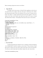
This research has developed an easy to use Microsoft Excel (visual basic) based pre
and post-processor for the above-mentioned program. Furthermore, the front-end
incorporates a leak-path geometric diagram for visual analysis of labyrinth leak path and
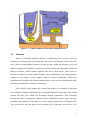
tooth location. In addition, a parametric study is performed on eye seal and balance piston
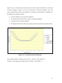
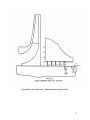
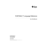
labyrinth seal shown in Figure 1-1.
1
Figure 1-1 Typical compressor labyrinth configuration [14]
1.2
Literature
Alford [1] identified labyrinth seal has a destabilizing effect on rotor whirl. He
considered two aerodynamic forces being the cause of the self-excitation of the rotor whirl.
One is due to circumferential variation of static pressure within the labyrinth cavity and
another exciting force being due to eccentricity of rotor causing circumferential variation of
blade-tip clearance. Alford further explained that due to these forces, whirl occurs in
direction of rotation at systems natural frequency. He concluded that by providing adequate
stiffness to rotor and/or to rotor support, whirl is reduced considerably. Alford also
concluded that Labyrinth seals having minimum flow at inlet are more desirable and stable
then having minimum flow clearance at discharge.
Since Alford, several authors have worked on theories for calculation of labyrinth
seal coefficients. Benckert and Wachter [16] presented formulas for lateral forces due to shaft
rotation and inlet swirl, which they developed through experiments. Their discussion
included the effects of operational conditions such as differential pressure, speed, inlet flow
conditions and geometry of labyrinth seal, on the spring characteristics of labyrinth seals.
They asserted the fact that lateral forces resulting out of labyrinth cavities have to be
2
accounted for in rotor dynamics and they permit a more accurate stability analysis. Benckert
further concluded that by placing swirl web (brakes) upstream of the labyrinth effectively
reduces the inlet swirl and in turn reduces the lateral force sensitivity.
Iwatsubo [2] performed theoretical analysis to evaluate the instability forces of
labyrinth seals in turbomachinery. He extended the fundamental equation proposed by
Kostyuk [1972] to consider the variation of chamber cross section, but he neglected the area
derivative in circumferential direction. Iwatsubo wrote continuity and momentum equation to
define the average circumferential velocity within a labyrinth chamber. His experimental
studies showed that the fluid in the labyrinth cavity forms a continuous vortex and flows in
circumferential direction.
In addition, Wyssmann et. al [17] also presented a theory for calculation of stiffness
and damping coefficients for centrifugal compressor labyrinth seals based on turbulent flow
calculations. Unlike Iwatsubo’s one-control-volume model, Wyssmann et. al [17] proposed
two-control-volume model for circumferential flow in a labyrinth chamber. One control
volume is for throughflow regime; the other is for the vortex region between labyrinth teeth
[18 (p.344)]. Wyssmann et. al [17] studied the influence of labyrinth geometry, operating
conditions, and mole weight on labyrinth cross-coupling stiffness. He concluded that
labyrinth coefficients are strongly dependent on tooth height and inlet swirl velocity.
Childs and Scharrer [19] extended Iwatsubo’s theories and compared it to
experimental results of Benckert and Wachter [16]. The model developed gave results that
were within 25% of the experimental results. This discrepancy could have been due to known
uncertainty in Wachter and Benckert experimental results. Their results included only the
influence of entry swirl and not the rotating shaft on cross-coupling stiffness. However, the
model was only valid for see-through type of labyrinth seal since the model fared very poorly
in comparison with interlocking and grooved seal data.
Kirk [20] developed a labyrinth analysis program, DYNLAB, based on theories of
Iwatsubo and Scharrer with several important extensions and modifications in the derivation
of the perturbation equations. Furthermore, he compared the results of DYNLAB to full-load
3
shop test data and Childs’ [19] computer program results. The static seal comparison was in
excellent agreement for both tooth on stator and full labyrinth design [20]. In addition, the
comparisons for full labyrinth at rotor speed of 9540 rpm showed good agreement if the
perturbation is non-synchronous.
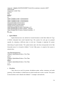
In an effort to improve and validate predictions of Bulk-Flow approaches, theories of
Iwatsubo, Childs and Scharrer, and Kirk, Moore [12] utilized three-dimensional
computational fluid dynamics to model the Labyrinth seal flow path by solving the Reynolds
Averaged Navier Stokes equations. His study utilized a CFD code—SCISEAL, which uses a
three-dimensional whirling method developed by Athavale et al [21]. Moore benchmarked
the CFD code by modeling the experimental data presented by Pelletti in 1990 for his
master’s thesis. He further compared the CFD results to Kirk’s and Scharrer’s Bulk-Flow
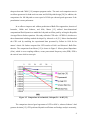
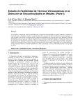
theories. The comparison from Moore [12] is shown in Figure 2. Moore plotted Impedance
(N/m), which is cross-coupling stiffness, versus processional frequency ratio (PFR). PFR is
the ratio of rotor whirl to rotor spin.
Figure 1-2 Comparison of seal models, 16 krpm, Pr = 0.403 [12].
The comparison showed good agreement of CFD to Kirk’s, whereas Scharrer’s had
greatest deviation [12]. CFD performs labyrinth coefficients and leakage analysis accurately,
4
but unfortunately has a drawback of computational time. Bulk-flow programs on the other
hand can perform analysis in few seconds, but with reasonable accuracy. Bulk-flow
continues to be used for day-to-day lateral rotordynamic stability analysis in the industry [12].
Guo and Kirk [13] in 2005 utilized a commercial CFD program, CFX TASCFlow, to
calculate leakage and rotordynamic force components of a labyrinth seal. The leakage results
on comparison with DYNLAB results showed good agreement, whereas prediction of the
destabilizing force by DYNLAB was pessimistic as compared to TASCFlow.
5
CHAPTER 2
Pre- and Post- Processor Capabilities and
Layout
A preprocessor and post-processor for a Labyrinth seal analysis code written by Dr.
Kirk is developed to meet industry needs. The processor design utilizes Excel’s Visual Basic
for Application functions and macros. The preprocessor is designed in a simple Excel
spreadsheet to facilitate easy data entry of labyrinth geometry and gas properties. It exports
the data entered in to a fixed-format text file and feeds the file to the FORTRAN based
program, DYNLAB. The post-processor imports the output file generated by DYNLAB into
tables and generates plots to analyze the results.
This chapter covers the capabilities and describes the pre and post-processor layout.
The programming involved in designing the processors is discussed in chapter 3. The
preprocessor is comprised of three worksheets--Main, Geometric Parameters and Gas
Property sheet.
2.1
Program Capabilities
LabyXL is a labyrinth type gas seals analysis program that uses a bulk flow small
perturbation solution to solve for the stiffness and damping characteristics of the labyrinth
gas seal. Gas leakage, pressure and temperature are also determined. The major features of
LabyXL preprocessor and post-processor can be summarized as follows:
1. The program is capable of importing and generating a data file. Refer to Figure A-1 in
Appendix A for a sample data file.
6
2. It provides a table for Geometric Parameters and Speed Case Parameters for easy
understanding and data input.
3. All input boxes are color-coded (Figure 2-1) to identify if the variable is required or
default could be used.
4. On opening the ‘Geometric Diagram’ sheet (after entering labyrinth geometric data), a
macro generates the leak path geometric diagram for better understanding of the
labyrinth geometry.
5. Gas property section provides a viscosity and temperature calculator for converting
centipose units to Lbm / (Ft * s) and Fahrenheit to Rankine respectively.
6. Labyrinth options section provides a field for input sheet name and path for easy
location of data sheet generated.
7. Post-Processor macro imports results from output text files into tables for data analysis.
8. In addition, it generates several plots for better analysis.
This program as a whole is a design tool for analysis of gas labyrinth seals typical of
centrifugal compressor eye, shaft, and balance drum configurations. The major advantage of
the labyrinth code is the ability to estimate the seal entrance swirl, given the impeller tip
swirl, which is a standard output of any aerodynamic design code. The program has been
tested and selected as the program of choice for toothed labyrinth designs by three major
OEM compressor companies and two major oil companies in the US. The program is being
used for last 20 years at these companies, and used as a consulting tool for the past 22 years.
The program can evaluate tooth on rotor, on stator or interlocking teeth. The seal can be
straight through or stepped. The program input can be adjusted to estimate the influence of
honeycomb seal designs with typical cell size.
2.2
Preprocessor Design Layout
The LabyXL is an easy-to-use program, incorporated in Microsoft Excel spreadsheet.
The spreadsheet consists of various macros in form of Buttons to automate series of tasks.
The section discusses the layout of these macros and input fields. Macros are discussed in
detail in the next chapter. The data input for the spreadsheet is divided in four parts – Control
7
Parameters (Figure 2-2), Geometrical Parameters (Figure 2-3), Gas Properties (Figure 2-5)
and Labyrinth Options (Figure 2-7).
The input fields are color-coded to help the user identify if input is required or not.
Figure 2-1 is a chart showing different color codes and its significance. Three comment lines
are provided for remarks necessary for the proper labeling of the data set. The four input
sections are discussed in the following section.
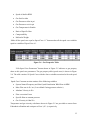
Figure 2-1 Input field color chart
1. Control Parameters
Control Parameters are the parameters required to run the Labyrinth seal analysis, it
includes the following variables:
•
The Speed of the Rotor in RPM
•
Number of cases to run – Range 1 to 10 cases
•
Type of Whirl
o Synchronous
o Non-Synchronous
•
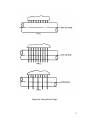
Labyrinth Series
o All axial chambers ( Refer to Figure B-3 in Appendix B)
o Radial chambers before and/or after the Laby ( Refer to Figure B-4 in
Appendix B)
o Radial chambers after the Laby ( Refer to Figure B-5 in Appendix B)
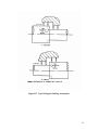
•
Labyrinth Type ( Tooth Orientation – Refer to Figure B-6 in Appendix B)
o Tooth on Stator
o Tooth on Rotor
8
o Interlocking
•
Step Shafting Data
o The Step shafting Pressure Option ( Refer to Figure B-7 in Appendix B)
o The number of iterations on swirl for Stepped Shafting and for Temperature
Calculation
Figure 2-2 Control Parameters
Figure 2-3 Geometrical Parameters
9
2. Geometrical Parameters
This section shown in Figure 2-3 consists of geometrical variables. The section is further
divided into two sections – Chambers and Chamber # 1. Chamber section consists of
following variables:
•
The last tooth number at which the radial chambers end before the Laby
•
The last tooth number at which the radial chambers end after the Laby
•
Total number of teeth on the seal
•
Range of teeth for the Stiffness and Damping calculation
•
Surface constants
o YNR
o YNS
o YMR
o YMS
A checkbox is provided next to all surface constants to give an option to make all
surface constants equal for all chambers. Thus, if a check mark is placed in the checkbox
then the program will use a default value as indicated. A different value for surface constants
could also be used by not placing a checkmark in the checkbox provided, and entering the
desired value in the Geometric Parameter table shown in Figure 2-4.
The Chamber # 1 section of the Geometrical Parameter section consists of tooth
geometry of chamber # 1; refer to Figure B-2 in Appendix B. It consists of the following
variables:
•
Tooth Height
•
Tooth Spacing
•
Tooth Clearance
•
Shaft Radius
By placing a checkmark in the checkbox next to any geometric variable and clicking the
“Make all chamber equal to chamber # 1” button makes that variable value equal for all
chambers in the geometric parameter table shown in Figure 2-4.
10
Figure 2-4 Geometric Parameter Table
By clicking on the “Edit Chamber” button shown in Figure 2-3 chamber parameters can
be edited. Edit chamber button will open the Geometric Parameter table shown in Figure 2-4.
The table consists of 50 chamber parameters with the above variables associated with each
chamber.
3. Gas Properties
Figure 2-5 shows gas property parameters. This section is further divided in two subsections – Speed case # 1 and Speed Case Constants. Speed Case # 1 section consists of the
following variables:
Figure 2-5 Gas Properties
11
•
Speed of shaft in RPM
•
Gas Swirl at inlet
•
Gas Pressure at inlet in psi
•
Gas Pressure at exit in psi
•
Gas Temperature in Rankin
•
Ratio of Specific Heat
•
Compressibility
•
Molecular Weight
“Make all the speed case equal to Speed Case # 1” button makes all the speed case variables
equal to variables of Speed Case # 1.
Figure 2-6 Gas Properties Table
“Edit Speed Case Parameters” button shown in Figure 2-5 redirects to gas property
sheet to edit speed case parameters. The gas property table (speed cases) is shown in Figure
2-6. The table consists 10 Speed Cases with the above variables associated with each speed
case.
Speed Case Constants section consists of the following variables:
•
System Natural Frequency and Non-Synch Perturbation Whirl Rate in RPM
•
Mass Flow rate in lb / sec ( Leave blank if using pressure solution )
•
Absolute Velocity in Ft/s
•
Flow correction Factor
•
Specific Heat at constant pressure
•
Gas Viscosity in Lbm/Ft/s
Temperature and gas viscosity calculators shown in Figure 2-5 are provided to convert from
Fahrenheit to Rankine and centipose to Lbm / (ft * s) respectively.
12
4. Labyrinth Options
This section shown in Figure 2-7 shows the computing options, it has the following
variables:
•
Maximum number of Solution iterations ( default = 50)
•
Velocity Tolerance ( default = 1e-4 x RS x omega )
•
Pressure Tolerance ( default = 1e-2 )
•
Mass Flow Tolerance ( default = 1e-4 )
•
YNR Ratio Factor
•
YNS Ratio Factor
•
YMR Cross Flow Factor ( 0 = yes )
•
YMS Cross Flow Factor ( 0 = yes )
Figure 2-7 Labyrinth Options
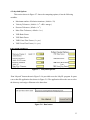
“Run Labyseal” button shown in Figure 2-8 is provided to run the LabyXL program. It opens
a save-data-file application box shown in Figure 2-9. The application allows the user to select
the directory and assign a filename to the data sheet.
Figure 2-8 Run button
13
Once the user saves the data file, a command prompt window pops-up, user should wait for it
to close and then click the Ok button to view the results. To save a data file without running
the analysis a “Generate Data File” button is provided. Location of the data file generated is
saved in the “Path and data sheet name” box.
Figure 2-9 Save Data File Application box
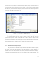
The LabyXL program also has a macro to import a LabyXL data file. Data files
generated from previous version of Labyrinth Seal can also be imported. “Import a Data
File” button is situated above the comment lines on the top of the Main Sheet. “Reset Fields”
button situated next to the “Import a Data File” button erases all the data fields.
2.3
Post-Processor Design Layout
The post-processor is designed to import data from output file into tables to organize
the results. Several plots are generated to study gas properties in various chambers. If
multiple cases are run, then parametric study can be performed as illustrated in Chapter 4.
Furthermore, the program provides the user with a diagram of the leak path geometry. This
14
helps the user to understand the radial and axial tooth location and fluid flow. Leak Path
Geometric diagram in Figure 2-10 can be found on the ‘Geometric Diagram’ sheet. The
macro automatically generates the diagram on entering the tooth geometry. Capabilities of
the diagram are summarized below:
•
It clearly identifies rotor and stator boundaries.
•
The radial and axial teeth (K & C teeth) are explicitly displayed.
•
Leak path can be accurately modeled.
•
The diagram self-adjusts itself to any changes made to the geometric parameter table.
Figure 2-10 Leak-Path Geometric Diagram
The output of LabyXL comprises of two sheets – ‘Results A’ and ‘Results B’.
‘Results A’ sheet displays two tables shown in Table 2-1 and Table 2-2.
15
Table 2-1 Results table – ‘Results A’ sheet
Table 2-1 shows the following variables:
•
Chamber number
•
Radius
•
Area of the chamber
•
ASL ( Area wetted stator length )
•
ARL ( Area wetter rotor length )
•
HYD. Diameter (Hydraulic diameter )
•
Swirl for various cases
Table 2-2 shows a detail list of variables for various speed cases generated. Maximum
number of ten speed cases can be analyzed.
16
Table 2-2 List of various speed case results
‘Results B’ sheet displays Mach number, Temperature, Pressure and Pressure step for each
chamber for various speed cases. Table 2-3 shows the table of results on ‘Results B’ sheet.
Table 2-3 Results table – ‘Results B’ sheet
17
‘Results A’ sheet has the following plots:
•
Swirl Vs Chamber ( Figure 2-11 )
•
Area, ASL, ARL and HYD. DIA Vs Chamber ( Figure 2-12 )
•
Effective Damping & Stiffness Vs Speed Cases ( Figure 2-13 )
Swirl Vs Chamber
1.2
Sw irl Case # 1
1
Sw irl Case # 2
Swirl
0.8
Sw irl Case # 3
Sw irl Case # 4
0.6
Sw irl Case # 5
0.4
Sw irl Case # 6
Sw irl Case # 7
0.2
Sw irl Case # 8
Sw irl Case # 9
0
0
2
4
6
8
10
12
Sw irl Case # 10
Chamber
Figure 2-11 Plot of Swirl Vs Chamber
Figure 2-12 Plot of Area, ASL, ARL and HYD. DIA Vs Chamber
18
Figure 2-13 Plot of Effective Damping & Stiffness Vs Speed Cases
Labyrinth seal designer and rotordynamists are mostly interested in reducing the
effective cross-coupling stiffness (Qe). Forward whirling can be minimized and instability
problem can be solved, by reducing Qe. Figure 2-13 shows a plot of Effective stiffness (Qe)
and Effective damping for various speed cases. Thus, this plot is crucial for stability analysis.
‘Results B’ sheet has the following plots:
•
Mach Number Vs Tooth ( Figure 2-14 )
•
Temperature Vs Chamber ( Figure 2-15 )
•
Pressure Vs Chamber ( Figure 2-16 )
19
M ach No. Vs Tooth
1
Mach No.
0.8
Speed Case # 1
0.6
Speed Case # 2
0.4
Speed Case # 3
0.2
0
0
5
10
15
Tooth
Figure 2-14 Plot of Mach No. Vs Tooth
Temperature Vs Chamber
665
Temperature(°R)
660
655
650
Speed Case # 1
645
Speed Case # 2
640
Speed Case # 3
635
630
625
620
0
5
10
15
Chamber
Figure 2-15 Plot of Temperature Vs Chamber
Figure 2-16 Plot of Pressure Vs Chamber
20
CHAPTER 3
LabyXL Macros
A macro is a set of commands including functions that are stored in a Microsoft
Visual Basic module and can be run whenever user needs to perform a task. LabyXL
program spreadsheet comprises of preprocessor and post-processor macros in form of check
box, text box, option buttons and command buttons. This chapter illustrates preprocessor and
post-processor macros and serves as a technical user’s manual.
3.1
Preprocessor Macros
The preprocessor macros are formulated to provide a user-friendly interface for easy
data entry. Input data is processed into an output fixed-format data file, which serves as an
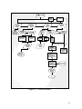
input data file for DYNLAB. A schematic representation of the process is shown in Figure 31. The post-processor starts after the Run Labyseal button, and includes the geometric leak
path diagram as seen in the flowchart. Likewise, the preprocessor is comprised of everything
above the Run Labyseal button. Input fields, process macros and results are represented by
parallelograms, rectangle and display symbol respectively.
21
Figure 3-1
Process Flowchart
22
Macros consisting of preprocessor macros are as follows:
Import Data file
•
The Import data file macro opens a GetOpenFileName application, so that the user
can search the file on his computer, then select, and import it. The file has to be a LabyXL
data file generated by either by Run Labyseal button or Generate Data File button, shown in
Figure 2-8 in chapter 2. A sample of the data file can be found in the Appendix A. The macro
imports all the values for the LabyXL data fields from the data file. The macro is located
under Microsoft Excel Objects – Sheet1(Main). Partial code for the macro is shown below.
Private Sub CommandButton2_Click()
Dim fileToOpen As Variant
fileToOpen = Application _
.GetOpenFilename("Text Files (*.txt), *.txt, Dat Files (*.dat), *.dat, All Files(*.*), *.*")
If fileToOpen = False Then
Exit Sub
End If
Open fileToOpen For Input As #1
Line Input #1, d
Line Input #1, e
Sheet1.Range("E79") = fileToOpen
Sheet1.TextBox1.Value = Mid(A, 1, 80)
Sheet1.TextBox3.Value = Mid(c, 1, 80)
Sheet1.Range("F15") = Mid(e, 51, 10)
If Mid(e, 70, 1) = 1 Then
Sheet1.OptionButton2.Value = True
Else
Sheet1.OptionButton1.Value = True
End If
If bbb Mod 7 = 0 And bbb <> 0 And bbb <> Mid(f, 59, 2) Then
Line Input #1, h
aaa = 0
End If
•
Reset Data Fields
The Reset Data Fields macro prompts the user, by opening a message box displaying
“ALL FIELDS RESET! Click OK to continue or Cancel to quit”. If the user clicks on Cancel
then the macro ends but if the user clicks on OK, then the macro erases all the data fields.
The full macro could be found under Sheet1(Main). Sample of the code is shown below.
Private Sub CommandButton4_Click()
23
response = MsgBox("All FIELDS RESET! click OK to continue or cancel to QUIT",
vbOKCancel)
If response = vbOK Then
GoTo A
Else
GoTo d
End If
A:
Sheet1.TextBox1.Value = ClearContents
Sheet1.TextBox2.Value = ClearContents
Sheet1.TextBox3.Value = ClearContents
Range("E50:E52").ClearContents
Range("E45:E52").ClearContents
Range("I45:I49").ClearContents
Sheet3.Range("B5:I5").Interior.ColorIndex = 24
Sheet3.Range("B5:I5").Interior.Pattern = xlGray8
Sheet3.Range("B5:I5").Interior.PatternColorIndex = 2
d:
End Sub
•
Option Button
Option button macros are utilized in Control Parameters in the Main Sheet for Type
of Whirl, Labyrinth Series and Labyrinth Type. The options for each type are grouped
together by assigning a different name to each one. Grouping is important for proper
functioning of option buttons. The option button macro has been incorporated in the Run
Labyrinth macro. It is located in Module 7 of the VBA project. A sample of the syntax is
shown below.
Sub Datasheetgenerate()
If Sheet1.OptionButton4.Value = True Then
YY = 1
End If
If Sheet1.OptionButton5.Value = True Then
YY = 2
End If
If Sheet1.OptionButton6.Value = True Then
x=1
End If
•
Check box
Check boxes are used for pressure calculation option, surface constants, and tooth
geometry. If the checkbox is clicked then its value becomes true or else it is false. The syntax
for the checkbox can be found in the Module 7. A sample is shown below.
24
Sub chkbox7_click()
If Sheet1.CheckBox7.Value = True Then YNS = "0"
If Sheet1.CheckBox7.Value = False Then YNS = "1"
End Sub
Sub chkbox8_click()
If Sheet1.CheckBox8.Value = True Then YMR = "0"
If Sheet1.CheckBox8.Value = False Then YMR = "1"
End Sub
•
Make all Chambers equal to Chamber #1 button macro
The macro starts with prompting the user that if he is sure that he wants all chambers
parameters to be equal to chamber # 1 parameters. If the user clicks cancel, then the macro
ends but if the user clicks Ok (yes), then the macro verifies that are all the Chamber # 1
parameters entered or not. If any data field is empty then a message box flashes and asks the
user to input that parameter and the macro ends.
Private Sub CommandButton1_Click()
response = MsgBox("All current chambers will be equal to chamber 1", vbOKCancel)
If response = vbOK Then
GoTo A
Else
GoTo d
End If
A:
If Sheet1.Range("E37") = "" Then
MsgBox ("Please enter a value for Tooth Height")
GoTo d
End If
If Sheet1.Range("E38") = "" Then
MsgBox ("Please enter a value for Tooth Spacing")
GoTo d
End If
Considering, if all chamber parameters are entered then the macro checks for check marks
for tooth parameters and surface constants. If the value is false, meaning no check mark then
it will copy the given value in all the fields, for the user to edit any value. However, if the
value is true then it will copy the given value only for the first tooth and the remaining will
be blank. Shown below is a part of the above macro.
Dim i As Integer
i=0
If Sheet1.CheckBox2.Value = False Then
25
Do
sheet2.Cells(7 + i, 2) = Sheet1.Range("E37")
sheet2.Cells(7 + i, 2).Interior.ColorIndex = xlNone
i=i+1
Loop Until i = (Sheet1.Range("F29").Value)
Else
sheet2.Cells(7, 2) = Sheet1.Range("E37")
End If
i=0
If Sheet1.CheckBox3.Value = False Then
Do
sheet2.Cells(7 + i, 3) = Sheet1.Range("E38")
sheet2.Cells(7 + i, 3).Interior.ColorIndex = xlNone
i=i+1
Loop Until i = (Sheet1.Range("F29").Value)
Else
sheet2.Cells(7, 3) = Sheet1.Range("E38")
End If
i=0
If Sheet1.CheckBox7.Value = False Then
Do
sheet2.Cells(7 + i, 8) = 0.079
sheet2.Cells(7 + i, 8).Interior.ColorIndex = xlNone
i=i+1
Loop Until i = (Sheet1.Range("F29").Value)
Else
sheet2.Cells(7, 8) = 0.079
End If
Furthermore, the macro color-codes the geometric parameter table. The dummy cells
are colored grey with color index equal to 15; radial chambers before the laby are colored
light yellow with color index 36. The axial chambers for K & C calculation are colored tan
with color index of 40. Radial chambers after the laby are colored light green with color
index of 35. A sample of color coding syntax is shown below.
Sheets("Geometric Parameters").Range("B7:I56").ClearContents
Sheets("Geometric Parameters").Range("B7:I56").Interior.ColorIndex = 15
' shading color index 40 for axial chambers - k c calculation
Dim r As Integer
Dim q As Integer
r = Sheet1.Range("I30")
q = Sheet1.Range("I31")
p=q-r
26
t=0
s=0
Do Until p = t - 1
sheet2.Cells(6 + r + t, 2 + s).Interior.ColorIndex = 40
s=s+1
If s = 8 Then
s=0
t=t+1
End If
Loop
' shading for radial before laby
r = Sheet1.Range("F28")
t=0
s=0
Do Until t = r - 1
If r = 0 Then
GoTo z
End If
sheet2.Cells(7 + t, 2 + s).Interior.ColorIndex = 36
s=s+1
If s = 8 Then
s=0
t=t+1
End If
Loop
z:
b:
y:
sheet2.Range("B7:E7").Interior.ColorIndex = 24
sheet2.Range("B7:E7").Interior.Pattern = xlGray8
sheet2.Range("B7:E7").Interior.PatternColorIndex = 2
Sheet3.Range("B5:I5").Interior.ColorIndex = 24
Sheet3.Range("B5:I5").Interior.Pattern = xlGray8
Sheet3.Range("B5:I5").Interior.PatternColorIndex = 2
Sheets("Geometric Parameters").Select
d:
End Sub
•
Edit Chambers button macro
This macro is similar to Make all chamber equal to chamber # 1 macro. It checks for
missing geometric parameters and prompts the user if any data is missing, checks for check
marks and if check mark is present then colors the column grey ( dummy ) in the Geometric
Parameter table. Unlike the ‘Make all chambers equal’ macro, it does not copy or delete any
data from the table. In a nut shell the edit chamber macro, checks for any changes or missing
data and opens the Geometric Parameter sheet. Sample of the code is shown below.
27
Private Sub CommandButton5_Click()
If Sheet1.Range("E37") = "" Then
MsgBox ("Please enter a value for Tooth Height")
GoTo d
End If
If Sheet1.Range("E38") = "" Then
MsgBox ("Please enter a value for Tooth Spacing")
GoTo d
End If
Dim i As Integer
i=0
If Sheet1.CheckBox2.Value = False Then
Do
Sheet2.Cells(7, 2) = Sheet1.Range("E37")
Sheet2.Cells(7 + i, 2).Interior.ColorIndex = xlNone
i=i+1
Loop Until i = (Sheet1.Range("F29").Value)
Else
Sheet2.Cells(7, 2) = Sheet1.Range("E37")
End If
' shading for radial before laby
r = Sheet1.Range("F28")
t=0
s=0
Do Until t = r - 1
If r = 0 Then
GoTo z
End If
Sheet2.Cells(7 + t, 2 + s).Interior.ColorIndex = 36
s=s+1
If s = 8 Then
s=0
t=t+1
End If
Loop
z:
Sheet2.Activate
d:
End Sub
•
Make all Speed Cases equal to Speed Case # 1 button macro
The macro checks for Speed Case # 1 parameters. If any data field is empty then a
message box flashes and asks the user to input that parameter and the macro ends.
Considering all the parameters for Speed Case # 1 are entered, the macro prompts the user
28
that if he is sure that he wants all Speed cases to be equal. If the user clicks cancel, then the
macro ends but if the user clicks Ok, then the macro copies Speed case # 1 parameters to all
the remaining speed cases. For instance, if a user chooses five speed cases then the Make all
speed cases equal macro will make the first five speed cases equal and the remaining will be
colored grey.
Private Sub CommandButton3_Click()
If Sheet1.Range("E47") = "" Then
MsgBox ("Please enter a value for Pressure at Inlet")
GoTo d
End If
If Sheet1.Range("E47") = "" Then
MsgBox ("Please enter a value for Pressure at inlet")
GoTo d
End If
response = MsgBox("All Speed Cases will equal to Speed Case # 1", vbOKCancel)
If response = vbOK Then
GoTo A
Else
GoTo d
End If
A:
i=0
Do
Sheet3.Cells(5 + i, 8) = Sheet1.Range("E50")
Sheet3.Cells(5 + i, 8).Interior.ColorIndex = xlNone
i=i+1
Loop Until i = (Sheet1.Range("F16").Value)
i=0
Do
Sheet3.Cells(5 + i, 9) = Sheet1.Range("E52")
Sheet3.Cells(5 + i, 9).Interior.ColorIndex = xlNone
i=i+1
Loop Until i = (Sheet1.Range("F16").Value)
Sheet2.Range("B7:E7").Interior.ColorIndex = 24
Sheet2.Range("B7:E7").Interior.Pattern = xlGray8
Sheet2.Range("B7:E7").Interior.PatternColorIndex = 2
Sheet3.Range("B5:I5").Interior.ColorIndex = 24
Sheet3.Range("B5:I5").Interior.Pattern = xlGray8
Sheet3.Range("B5:I5").Interior.PatternColorIndex = 2
Sheets("Gas Properties").Select
d:
End Sub
29
•
Edit Speed Case button macro
The Edit Speed Case macro, similar to Make all speed case equal macro, verifies that
are all the Speed Case # 1 parameters entered or not. If any data field is empty then a
message box flashes and asks the user to input that parameter, and the macro ends. If there is
no missing data then, it copies parameters of Speed Case # 1 from the main sheet to the Gas
Property table, keeping the remaining speed cases undisturbed and it opens the Gas
Properties sheet. A sample of the code is shown below, and the code can be found in VB
applications Sheet1 (main).
Private Sub CommandButton6_Click()
Dim i As Integer
If Sheet1.Range("E47") = "" Then
MsgBox ("Please enter a value for Pressure at Inlet")
GoTo d
End If
If Sheet1.Range("E47") = "" Then
MsgBox ("Please enter a value for Pressure at inlet")
GoTo d
End If
Sheets("Gas Properties").Range("B5:I14").Interior.ColorIndex = 15
i=0
Do
Sheet3.Cells(5, 2) = Sheet1.Range("F15")
Sheet3.Cells(5 + i, 2).Interior.ColorIndex = xlNone
i=i+1
Loop Until i = (Sheet1.Range("F16").Value)
Sheet2.Range("B7:E7").Interior.ColorIndex = 24
Sheet2.Range("B7:E7").Interior.Pattern = xlGray8
Sheet2.Range("B7:E7").Interior.PatternColorIndex = 2
Sheet3.Range("B5:I5").Interior.ColorIndex = 24
Sheet3.Range("B5:I5").Interior.Pattern = xlGray8
Sheet3.Range("B5:I5").Interior.PatternColorIndex = 2
Sheets("Gas Properties").Select
d:
End Sub
•
Viscosity Calculator macro
This macro converts gas viscosity from centipose units to Lbm / (ft*sec). It opens an
Input Box for user to enter gas viscosity. The equation for the conversion is:
Gas viscosity (Lbm/ft/sec) = cp * 12 * 386 * 1.45E-7
(3-1)
30
As soon as the macro receives the input in centipose, it converts it to Lbm/ft*sec and pastes it
in the gas viscosity input field. The syntax is shown below.
Private Sub CommandButton8_Click()
Dim myvalue
myvalue = InputBox("Enter a value for centipose(cp)" & Chr(10) & Chr(10) & "Gas Visocity =
cp*12.0*386.0*1.45E-7", "Gas Visocity Calculator")
If myvalue = "" Then
GoTo h
Else
Sheet1.Range("F63").Value = (myvalue * 12 * 386 * 0.000000145)
End If
h:
End Sub
•
Generate Data File macro
As the name implies, the macro extracts data from the Excel spreadsheets into a fixed
format text file. The following are the steps in which the macro saves the data.
1.
The macro begins by calling a function checkfields, to check for any missing data on
the main sheet. If any data is missing, a message-box displaying the missing
parameter pops-up, and the macro ends. The function uses a counter called trapy to
check for missing fields. If any data is missing then trapy will be less than 25, and if
trapy is less than 25 then the macro is forced to end. The function is located in
Module 7 and the Generate data file macro is located in Sheet1 (Main) in VBA
project. Sample syntax is shown below.
Function checkfields()
trapy = 0
Dim mycheck
IsNumeric (Sheet1.Range("F15").Value)
If IsNumeric(Sheet1.Range("F15").Value) And Sheet1.Range("F15").Value <> ""
Then
trapy = trapy + 1
Else
MsgBox ("Rotor Speed (F15) field Missing!!")
End If
If IsNumeric(Sheet1.Range("F59")) And Sheet1.Range("F59") <> "" Then
trapy = trapy + 1
Else
MsgBox ("Absolute Velocity (F59) field Missing!!")
31
End If
End Function
Private Sub CommandButton7_Click()
Call checkfields
If trapy < 25 Then
GoTo endit
End If
2.
The macro calls all the Checkbox subroutines to check their values. Zero is assigned
to the variable if the value is true and one if the value is false. Syntax is shown below.
Call chkbox2_click
Call chkbox3_click
Call chkbox4_click
Call chkbox5_click
Call chkbox6_click
Call chkbox7_click
Call chkbox8_click
Call chkbox9_click
Sub chkbox7_click()
If Sheet1.CheckBox7.Value = True Then YNS = "0"
If Sheet1.CheckBox7.Value = False Then YNS = "1"
End Sub
Sub chkbox8_click()
If Sheet1.CheckBox8.Value = True Then YMR = "0"
If Sheet1.CheckBox8.Value = False Then YMR = "1"
End Sub.
3.
The macro calls for a function, GetSaveAsTxtFilename. The function opens an
application called GetSaveAsFilename. The application displays the standard opendialog-box and gets a file name and path from the user to save it. The file path and
name is then saved on the “Main” sheet in cell E79.
Call GetSaveAsTxtFilename
If fun = 1 Then
GoTo Dumo
‘Sub ends
End If
Function GetSaveAsTxtFilename(Optional InitialFileName As Variant) As String
Dim vFilename As Variant
fun = 0
If IsMissing(InitialFileName) Then
InitialFileName = ""
32
End If
vFilename = _
Application.GetSaveAsFilename( _
InitialFileName:=InitialFileName, _
Title:="Please select a folder and name to save the file", _
fileFilter:="Text files *.txt (*.txt),")
If vFilename = False Then
GetSaveAsTxtFilename = ""
‘if cancel is pressed
fun = 1
Else
GetSaveAsTxtFilename = vFilename
Sheet1.Range("E79") = vFilename
End If
End Function
Set filename = Sheet1.Range("E79")
4.
The data file created by the user is opened to save the data. Before printing any data
in, the macro truncates the path name from the string variable, filename, in order to
get just the name of the data file. This is done to save the results file in the same name
but with .out extension. The string variable, temp5, stores the truncated name of the
data file.
Open filename For Output As #1
Dim Temp1 As String
Dim Temp2 As String
Dim temp4 As String
Dim Temp3 As Integer
Dim temp5 As String
temp$ = CurDir
Temp1$ = Len(filename)
Temp2$ = Len(temp$)
Temp3 = Temp1$ - Temp2$ - 1
temp4 = Right$(filename, Temp3)
temp5 = Mid(temp4, 1, Temp3 - 4)
5.
The macro starts printing the data from the Mainsheet to the data file, which includes
variables of checkboxes, option buttons, and textboxes. Each print command prints
data on the new line.
If Sheet1.OptionButton1.Value = True Then
y=0
End If
Print #1, Sheet1.TextBox1.Value
Print #1, Sheet1.TextBox2.Value
33
Print #1, Sheet1.TextBox3.Value
Print #1,
Print #1, "CROTOR SPEED-RPM;NSPD;TYPE WHIRL,0=SYN,1=NON;SPD =" &
Format(Range("F15"), "000.00E+00;-00.00E+00") & " " & Format(Range("F16"),
"00") & " " & Format(y, "0")
Print #1, "CRAD OPT;SERIES;TYP 1 STA./2 ROT/3 I-LOCK;STEP;I;IRS=" &
Format(Range("F28"), "00") & "ST=" & Format(YY, "0") & Format(x, "0"); " IS=" &
Format(ISS, "0") & " IB=" & Format(Range("F24"), "0")
6.
Geometrical Parameter table variable is printed in a way such that maximum of seven
values can be printed on one line. If it exceeds seven then it prints on the next line.
This is achieved my using the Mod function, it returns the remainder after number is
divided by divisor. Here the divisor is seven. Thus, if the function returns a zero then
the macro prints to the next line. Printing of only seven values on a line is done to
follows the DYNLAB data input file format. The syntax is shown below.
Print #1, "CTOOTH HEIGHT(IF KEY=1,INSERT LINE(S) 7G10.2)KEY =" &
Format(keyb, "0000000000") & "B=" & Format(Sheet1.Range("E37"), "+00.00E+00")
If (keyb = "1") Then
n=0
For Each toothheight In Sheet2.Range("B7", Sheet2.Range("B7").End(xlDown))
strnme = toothheight.Value
If n Mod 7 = 0 And n <> 0 Then
Print #1,
End If
Print #1, Format(toothheight, "000.00E+00;-00.00E+00");
n=n+1
Next toothheight
Print #1,
End If
7.
The macro uses a Do loop to print values from the gas property table to the data sheet.
It prints until variable caseno exceeds variable NSPD. Variable NSPD stores the
number of cases selected by the user. If printing is successful then a message box
displays the name and path of the filename. Syntax is shown below.
Print #1, "C SPEED SWIRL
PS
VABS
MUXG
CP
Ncr"
PE
TABS
Z
GAMMA
MW
Dim caseno As Integer
caseno = 1
Do Until caseno > NSPD
Print #1, Format(Sheet3.Range("B" & 4 + caseno), "000.00E+00;-00.00E+00") &
Format(Sheet3.Range("C" & 4 + caseno), "000.00E+00;-00.00E+00") &
34
Format(Sheet3.Range("D" & 4 + caseno), "000.00E+00;-00.00E+00")
Format(Sheet3.Range("E" & 4 + caseno), "000.00E+00;-00.00E+00")
Format(Sheet3.Range("F" & 4 + caseno), "000.00E+00;-00.00E+00")
Format(Sheet3.Range("G" & 4 + caseno), "000.00E+00;-00.00E+00")
Format(Sheet3.Range("H" & 4 + caseno), "000.00E+00;-00.00E+00")
Format(Sheet3.Range("I" & 4 + caseno), "000.00E+00;-00.00E+00")
Format(Sheet3.Range("J" & 4 + caseno), "000.00E+00;-00.00E+00")
Format(Sheet3.Range("K" & 4 + caseno), "000.00E+00;-00.00E+00")
Format(Sheet3.Range("L" & 4 + caseno), "000.00E+00;-00.00E+00")
Format(Sheet3.Range("M" & 4 + caseno), "000.00E+00;-00.00E+00")
caseno = caseno + 1
Loop
&
&
&
&
&
&
&
&
&
Close #1
MsgBox ("Successfull! Data File saved in " & filename)
3.2
Post-Processor Macros
LabyXL’s post-processor is developed to model the labyrinth seal accurately and to
study influence of change in various parameters. The post-processor generates a gas leakpath graph with tooth location, for the user to visualize the labyrinth geometry. Furthermore,
it imports and tabulates the results, and generates six different graphs to better analyze the
results. The post-processor comprises of two major macros – Geometric Diagram macro and
Run Labyseal macro.
•
Geometric Diagram macro
The macro automatically generates the leak path and tooth location of the labyrinth
seal. Stator and rotor boundaries formulate the leak path. Table 3.1 gives the detail
calculations for X and Y-axis coordinates for both stator and rotor boundary points.
Labyrinth teeth for K & C calculation are highlighted in black, whereas dummy teeth
are white. Refer to Figure 2-10 for the geometric diagram. Part of the macro is shown
below.
ActiveChart.SeriesCollection(1).Select
With Selection
.MarkerBackgroundColorIndex = 1
.MarkerForegroundColorIndex = 1
.MarkerStyle = xlNone
35
.Smooth = True
.Shadow = False
End With
Sheet6.Range("o3").Select
End If
ActiveSheet.ChartObjects("Chart 11").Activate
If Sheet1.OptionButton6.Value = True Then
ActiveChart.SeriesCollection(5).XValues = "='Geometric Diagram'!R35C22:R85C22"
ActiveChart.SeriesCollection(5).Values = "='Geometric Diagram'!R35C23:R85C23"
ActiveChart.SeriesCollection(5).Name = "=""K&C teeth"""
End If
36
0
B1 + SpacingT1
B2 + SpacingT2
B3 + SpacingT3
B4 + SpacingT4
B5 + SpacingT5
B6 + SpacingT6
B7 + SpacingT7
B8 + SpacingT8
B9 + SpacingT9
B10 + SpacingT10
B11 + SpacingT11
B12 + SpacingT12
B13 + SpacingT13
B14 + SpacingT14
B15 + SpacingT15
B16 + SpacingT16
B17 + SpacingT17
B18 + SpacingT18
B19 + SpacingT19
B20 + SpacingT20
Shaft rad.
Shaft rad.
Shaft rad.
Shaft rad.
Shaft rad.
Shaft rad.
Shaft rad.
Shaft rad.
Shaft rad.
Shaft rad.
Shaft rad.
Shaft rad.
Shaft rad.
Shaft rad.
Shaft rad.
Shaft rad.
Shaft rad.
Shaft rad.
Shaft rad.
Shaft rad.
Shaft rad.
Shaft rad.
Shaft rad.
Shaft rad.
Shaft rad.
Shaft rad.
Shaft rad.
Shaft rad.
Shaft rad. + Ht. + Clearance
Shaft rad. + Ht. + Clearance
Shaft rad. + Ht. + Clearance
Shaft rad. + Ht. + Clearance
Shaft rad. + Ht. + Clearance
Shaft rad. + Ht. + Clearance
Shaft rad. + Ht. + Clearance
Shaft rad.
Shaft rad.
Shaft rad.
Shaft rad.
Shaft rad.
Shaft rad.
Shaft rad.
Stator boundary
X – coordinate
Y – coordinate
(D)
(E)
B1 + Ht. + clearance
B2 + Ht. + clearance
B3 + Ht. + clearance
B4 + Ht. + clearance
B5 + Ht. + clearance
B6 + Ht. + clearance
B7 + Ht. + clearance
B8
B9
B10
B11
B12
B13
B14
B15 – Ht. – clearance
B16 – Ht. – clearance
B16 – Ht. – clearance
B17 – Ht. – clearance
B18 – Ht. – clearance
B19 – Ht. – clearance
B20 – Ht. – clearance
B# represents the cell in column B and the tooth row number
C# represents the cell in column C and the tooth row number
SpacingT# represents the spacing of the respective tooth number.
Clearance represents the clearance of the respective tooth
Ht. represents the height of the respective tooth
Shaft rad. represents the shaft radius of the respective tooth
Radial
teeth after
the
Labyrinth
Axial
teeth
Radial
teeth
before
labyrinth
Tooth
#
1
2
3
4
5
6
7
8
9
10
11
12
13
14
15
16
17
18
19
20
21
Rotor boundary
X- coordinate
Y- coordinate
(B)
(C)
Table 3-1 Rotor and Stator Boundary Line Calculation
37
•
Run Labyseal macro
Run Labyseal button macro includes the entire Generate Data sheet macro besides
it includes the following.
1.
The Run macro finishes all the tasks for Generate Data Sheet macro then it
generates a text file named answers.txt in a folder called Labyseal. The macro
prints the data-sheet path on the first line of answers.txt; on the second line, it
prints the output file name, with the same name as the Data file name but
with .out extension. On the third and fourth line, it prints current.out and
labxlin.txt. All the three output files have the same path as the data file. Once the
answers.txt file has been created, the Shell command first opens the command
prompt then the FORTRAN based executable program file called laby2008.exe.
The Run macro feeds answers.txt file to the executable program.
Open "C:\Labyseal\answers.txt" For Output As #1
Print #1, filename
Print #1, temp$ & "\" & temp5 & ".out"
Print #1, temp$ & "\current.out"
Print #1, temp$ & "\Labxlin.txt"
Print #1,
Close
cs = Environ$("COMSPEC")
Shell cs & " /c C:\Labyseal\laby2006.exe < C:\Labyseal\answers.txt",
vbMaximizedFocus
2.
The macro deletes all the contents of the results section. The syntax is
shown below.
Sheet4.Range("A14:Q120").ClearContents
Sheet5.Range("A11:G450").ClearContents
Sheet4.Range("A15:Q120").Font.Bold = False
Sheet5.Range("A11:G450").Font.Bold = False
Sheet4.Range("A15:Q120").Borders.LineStyle = xlNone
Sheet4.Range("A15:Q120").Font.ColorIndex = 1
Sheet5.Range("A11:G450").Font.ColorIndex = 1
Sheet4.ChartObjects.Delete
sheet4.Activate
Sheet5.ChartObjects.Delete
38
3.
The macro opens the data sheet saved by the user and acquires the directory
information. The output file “labxlin.txt” is found in that directory, and is
renamed to “labx.txt”. Before renaming the file the macro checks for
previously saved files and deletes them. A Do loop is used to rename the
file. The syntax is shown below.
A = Sheet1.Range("E79")
Open A For Input As #1
c = CurDir
d = CurDir & "\labxlin.txt"
labx = CurDir & "\labx.txt"
Close #1
If Len(Dir(labx)) > 0 Then Kill labx
‘’Test for previous files and delete them.
msg = MsgBox("Successful!! To see results click OK", vbOKOnly)
If msg = vbOK Then
Do Until Len(Dir(labx)) > 0
‘‘Begin a loop to test for final output file, labx.txt.
Name (d) As (labx)
‘‘Attempt to rename
‘‘will fail until temp.txt is closed
On Error Resume Next
Loop
Else
GoTo q
End If
4.
The macro opens labx.txt to extract data. It imports the data from the
labx.txt file to results section A and B. The macro uses the syntax ‘Line
Input #1, h’ to go to the next line in the text file. The data is imported in
three tables.
39
Open labx For Input As #1
Line Input #1, h
g = Mid(h, 2, 6)
Line Input #1, h
Line Input #1, h
Table1
Sheet4.Cells(14 + ccc, 6) = Mid(h, 42, 8)
Sheet4.Cells(14 + ccc, 6).Borders.LineStyle = xlContinuous
Sheet4.Cells(14 + ccc, 7) = Mid(h, 52, 8)
Sheet4.Cells(14 + ccc, 7).Borders.LineStyle = xlContinuous
ccc = ccc + 1
Line Input #1, h
Loop
Table 2
Sheet4.Cells(17 + ccc, 1) = "Rotor Speed[RPM]"
Sheet4’.Cells(18 + ccc, 1) = "Total Temp[Deg-R]"
Sheet4.Cells(19 + ccc, 1) = "Static Temp[Deg-R]"
Line Input #1, h
Sheet4.Cells(23 + ccc, 2 + ww) = Mid(h, 27, 10)
Sheet4.Cells(23 + ccc, 2 + ww).Borders.LineStyle = xlContinuous
Line Input #1, h
Sheet4.Cells(24 + ccc, 2 + ww) = Mid(h, 27, 10)
Sheet4.Cells(24 + ccc, 2 + ww).Borders.LineStyle = xlContinuous
‘' do loop for the speed cases from sheet3
Do Until t = 6
Sheet4.Cells(25 + ccc, 2 + ww) = Sheet3.Cells(5 + ww, 3 + t)
Sheet4.Cells(25 + ccc, 2 + ww).Borders.LineStyle = xlContinuous
ccc = ccc + 1
t=t+1
Loop
'‘data import starting from start teeth for KC
Line Input #1, h
Sheet4.Cells(25 + ccc, 2 + ww) = Mid(h, 27, 10)
Sheet4.Cells(25 + ccc, 2 + ww).Borders.LineStyle = xlContinuous
40
Table 3
Sheet5.Cells(11 + ss, 1) = "Speed Case # " & dd
Sheet5.Cells(11 + ss, 1).Font.Bold = True
Dim na As Integer
Do Until ss = (dd * 2 * Sheet1.Range("F29").Value) + 1 + (ww)
If IsNumeric(Mid(h, 2, 8)) Then
Sheet5.Cells(11 + ss, 2) = Mid(h, 2, 8)
Else
Sheet5.Cells(11 + ss, 2) = "=NA()"
Sheet5.Cells(11 + ss, 2).Font.ColorIndex = 2
End If
Sheet5.Cells(11 + ss, 2).Borders.LineStyle = xlContinuous
5.
The macro generates six plots:
• Swirl Vs Chamber
• Area, ASL, ARL & Hyd. Diameter Vs Chamber
• Effective Damping and Stiffness Vs Speed Cases
• Mach number Vs Tooth
• Temperature Vs Chamber
• Pressure Vs Chamber
The Run Labyseal macro calls a function called pressplot to generate Pressure Vs
chamber plot. Syntax is shown below.
Function pressplot()
Sheet5.Activate
Sheet5.Select
Dim nosteth As Integer
Dim num As Integer
Dim num2 As Integer
Dim casenum As Integer
casenum = 1
Dim startethrow As Integer
startethrow = 11
nosteth = Sheet1.Range("F29")
num = (2 * nosteth) + 11
41
num2 = 11
‘’ Adds the chart to the active sheet
Charts.Add
ActiveChart.ChartType = xlXYScatterSmooth
ActiveChart.SeriesCollection.NewSeries
ActiveChart.Location Where:=xlLocationAsObject, Name:="Results B"
‘’ Selects the type of chart
Do Until casenum = Sheet1.Range("F16") + 1
ActiveChart.SeriesCollection(casenum).Name = "='Results B'!R" & num2 & "C1"
ActiveChart.SeriesCollection(casenum).Values = "='Results B'!R" & startethrow &
"C6:R" & num & "C6"
ActiveChart.SeriesCollection(casenum).XValues = "='Results B'!R" & startethrow
& "C4:R" & num & "C4"
casenum = casenum + 1
num2 = num2 + (2 * nosteth) + 1
startethrow = startethrow + (2 * nosteth) + 1
num = num + (2 * nosteth) + 1
ActiveChart.Location Where:=xlLocationAsObject, Name:="Results B"
’’ Adds a new series to the active chart
ActiveChart.SeriesCollection.NewSeries
Loop
ActiveChart.SeriesCollection(casenum).Delete
‘’ Labels the X, Y axis and the title
With ActiveChart
.HasTitle = True
.ChartTitle.Characters.Text = "Pressure Vs Chamber"
.Axes(xlCategory, xlPrimary).HasTitle = True
.Axes(xlCategory, xlPrimary).AxisTitle.Characters.Text = "Chamber"
.Axes(xlValue, xlPrimary).HasTitle = True
.Axes(xlValue, xlPrimary).AxisTitle.Characters.Text = "Pressure"
End With
With ActiveChart
.HasAxis(xlCategory, xlPrimary) = True
.HasAxis(xlValue, xlPrimary) = True
End With
ActiveChart.Axes(xlCategory, xlPrimary).CategoryType = xlAutomatic
Set rngi = Sheet5.Range("I50:P66")
With Sheet5.ChartObjects(3)
42
‘’ Places the chart at the right position with the right size
.Top = rngi.Top
.Left = rngi.Left
.Width = rngi.Width
.Height = rngi.Height
End With
End Function
The Run Labyseal macro ends after calling the TempPlot and PressPlot functions.
43
CHAPTER 4
Parametric Study
Parametric study plays a vital role in understanding influence of various factors
governing the dynamics of a system. The objective of this parametric study is to examine
influence of different operating conditions and gas properties on effective cross-coupling
stiffness. Effect of synchronous and non-synchronous rotor whirl on parameters of major
influence is also examined. Investigation is performed on API Rotor Stability Survey
[2006], impeller # 1 eye and balance piston labyrinth seal models using LabyXL program
developed herein. This study will help rotordynamic analysts to solve instability
problems more efficiently.
This chapter covers modeling of all API survey labyrinth seals and comparison
with actual respondents. Furthermore, a parametric study is performed on API’s impeller
# 1 eye labyrinth and Balance Piston labyrinth seal.
4.1
API Seal Modeling and Comparison
In order to improve American Petroleum Institute (API) specifications, API
conducted a survey of several turbomachinery analysts to determine dynamic coefficients
of tilt pad bearing, first and last impeller eye labyrinth and labyrinth balance piston. This
research focuses on modeling of first and last impeller eye labyrinth and balance piston
labyrinth by utilizing LabyXL program.
44
The three labyrinth seals mentioned above are modeled using the parameters
provided by API, shown in Table 4.1. All labyrinth seals are modeled as teeth on rotor for
an operating speed of 21662 rpm. Swirl ratio of 0.7 and the critical speed location at
operating of 6700 cpm is assumed. The absolute velocity for each labyrinth seal was
calculated by using,
Vabs = rω * sr
where,
(4-1)
Vabs = absolute velocity in ft/sec
r
= shaft radius in inches
ω
= shaft speed in radians/sec
sr = swirl ratio of gas at inlet
Table 4-1 API labyrinth seal parameters
Impeller eye # 1
Impeller eye # 5
Balance Piston
Nitrogen
Nitrogen
Nitrogen
Speed (rpm)
21662
21662
21662
Critical speed (cpm)
6700
6700
6700
Inlet Pressure (psi)
1548
3035
3035
Discharge Pressure (psi)
1201
2637
1201
Inlet temperature (°R)
585.7
805.7
805.7
4
4
11
Diameter (in)
5.25
5.25
5.00
Tooth height (in)
0.089
0.089
0.100
Tooth spacing (in)
0.098
0.098
0.155
Tooth clearance (in)
0.005
0.005
0.005
1.02
1.104
1.104
28..0134
28..0134
28..0134
Specific Heat Ratio
1.535
1.502
1.502
Viscosity (cP)
0.021
0.026
0.026
Operating conditions
Gas
Geometric Parameters
# of Teeth
Gas Properties
Compressibility
Mole weight
45
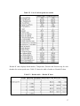
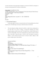
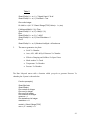
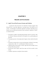
Three cases are run using the above parameters. Table 4-2 shows results for synchronous
and non-synchronous type of whirl. Effective cross-coupling stiffness is calculated using
equation 4-2 developed by Kirk [5].
Qe = Kxy – Cxx*ωNcr
(4-2)
where,
Qe
= effective cross-coupling stiffness in lbf/in
Kxy
= cross-coupling stiffness in lbf/in
Cxx
= direct damping in lbf-s/in
ωNcr = rotor natural frequency in rad/sec.
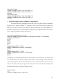
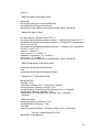
Results are then compared to the results of the API survey respondents in Figure
4-1. Two respondents with major deviation have been removed from the comparison to
get a better insight.
Table 4-2 Results for the dynamic coefficients of the API survey
Stiffness (lbf/in)
Imp #
5 eye
laby
Bal.
Piston
Qe
Kxx
Kxy
Kyx
Kyy
Cxx
Cxy
Cyx
Cyy
(lbf/in)
Syn
-641.06
4193.50
-4193.50
-641.06
2.08
0.10
-0.10
2.08
2734.6
NonSyn
-786.11
2623.20
-2623.20
-786.11
0.64
0.24
-0.24
0.64
2174.9
Syn
-1288.10
5379.10
-5379.10
-1288.10
2.66
0.31
-0.31
2.66
3510
NonSyn
-1149.30
3413.00
-3413.00
-1149.00
0.84
0.35
-0.35
0.84
2827.9
Syn
-75232
23923
-23923
-75232
10.23
31.00
-31.00
10.23
16741
NonSyn
-19564
6581.9
-6581.9
-19564
1.41
7.00
-7.00
1.41
5592
Component
Imp #
1 eye
laby
Damping (lbf-sec/in)
46
Eye#1
Eye#5
BP
15.0
10.0
5.0
25
#24
Eye#1
&23
22
21
LabyXL synchronous results
shown as RM-syn.
LabyXL non-synchronous
results shown as RM-non.
BP
20
0.0
1
2
3
4
8
8a
10
RM-syn
12
13
14
RM-non
Qeff Normalized
20.0
Respondents
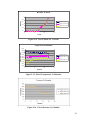
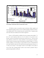
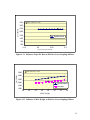
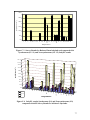
Figure 4-1 API survey results [22] for Normalized Destabilizing Force compared
with LabyXL Synchronous and Non-synchronous results.
API stiffness results are normalized using the minimum stiffness supplied, and
same respondents damping results are used to normalize damping coefficients. Effective
cross-coupling (Qeff) is then calculated using the normalized values. Comparison plots
with actual values (not normalized) can be found in Appendix C.
Kocur et. al [22] studied the variability of the survey response and concluded: “To
date, there remain significant differences across the industry in the prediction of the
dynamic coefficients for fluid film tilt pad bearings and labyrinth seals.” Well, one of the
major differences could be due to using synchronous or non-synchronous assumption.
LabyXL results for synchronous and non-synchronous are plotted in Figure 4-1. As far as
LabyXL credibility is concerned, Kirk et. al [8] and Moore [12] have verified DYNLAB
(now called LabyXL) results with CFD, which has shown good agreement. Moreover, it
is clearly seen in Figure 4-1 that LabyXL results lie in the ballpark of the median of
survey results. Thus, assuming LabyXL results are near accurate a parametric study is
performed using LabyXL on API seals.
47
4.2 Influence of Various Parameters of Labyrinth Eye Seal on Effective
Cross-coupling Stiffness
Effects of operating conditions and gas properties on effective cross-coupling
stiffness (aerodynamic excitation) are investigated by using Impeller # 1 eye labyrinth
seal API model. All parameters from Table 4.1 remain constant except for the parameter
under investigation. In the parametric study figures, the reference case, API LabyXL
result, is circled in black.
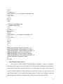
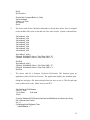
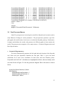
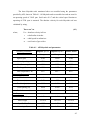
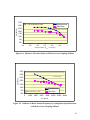
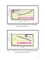
The results shown in Figure 4-2 and 4-3 make clear that increase in rotor speed
and gas inlet swirl ratio aggravate the excitation. The swirl ratio, quite interestingly, at
least for this particular case, if reduced to 0.4 would make the destabilizing force negative.
Meaning, the destabilizing force would act as a stabilizing force or could even produce
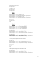
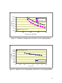
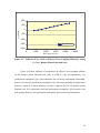
backward rotor whirl instead of forward. Pressure ratio on the other hand if increased
reduces the magnitude of Qe, as seen in Figure 4-4. (Note: increasing the pressure ratio
for labyrinth seal would mean reducing the pressure drop across the seal).
All
conclusions made above apply to both – synchronous and non-synchronous type of whirl.
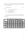
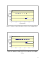
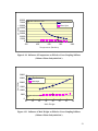
Figure 4-5 and 4-6 show results of variation of first natural frequency (Ncr) by
setting rotor speed constant at 21662 rpm and by setting rotor speed equal to Ncr
respectively. By varying Ncr, rotor whirl frequency (at first natural frequency) may also
vary; since, LabyXL assumes both equal. The cross-coupling stiffness (Kxy) and direct
damping (Cxx) remain constant for the synchronous case as expected, but Qe
significantly decreases (refer to Figure 4-5) as Ncr increases because, in order to calculate
Qe (Equation 4-2), Ncr is multiplied with Cxx and subtracted from Kxy. For the nonsynchronous case, Kxy and Cxx increase with increase in Ncr (not shown in the figure).
However, Qe gradually decreases due to substantial increase in direct damping. Due to
this gradual reduction, Qe for the non-synchronous case eventually becomes greater than
Qe for the synchronous case when Ncr is about half the rotor speed. When rotor speed is
set equal to Ncr (seen in Figure 4-6), in other words when synchronous and nonsynchronous conditions are same, the system may experience resonance or critical
48
condition and Qe results in a negative value and further decreases as rotor speed and Ncr
increase.
3730
API reference case
Qe (lbf/in)
3230
2730
2230
1730
1230
Synchronous
Non-Syn
730
230
0
5000
10000
15000
20000
25000
30000
Rotor Speed (RPM)
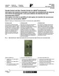
Figure 4-2 Influence of Rotor Speed on Effective Cross-Coupling Stiffness
4500
API reference case
Qe (lbf/in)
2500
500
Synchronous
Non-syn
-1500
-3500
-5500
0
0.2
0.4
0.6
0.8
1
Swirl Ratio
Figure 4-3 Influence of Inlet Gas Swirl Ratio on Effective Cross-Coupling Stiffness
49
3730
Qe (lbf/in)
Synchronous
Non-Sync
API reference case
3230
2730
2230
1730
1230
730
230
0.4
0.5
0.6
0.7
0.8
0.9
1
Pressure Ratio ( Pinlet = 1548 psi)
Figure 4-4 Influence of Pressure Ratio on Effective Cross-Coupling Stiffness
3730
Qe (lbf/in)
3230
N =21662 rpm
2730
2230
1730
1230
Synchronous
730
API reference case
Non-Syn
230
0
2000
4000
6000
8000
10000 12000 14000
Ncr (RPM)
Figure 4-5 Influence of Rotor Natural Frequency by setting Rotor Speed Constant,
on Effective Cross-Coupling Stiffness
50
0
Qe (lbf/in)
-500
-1000
-1500
Synchronous
-2000
0
5000
10000
15000
20000
25000
Rotor Speed (N=Ncr)
Figure 4-6 Influence of Rotor Natural Frequency by setting Ncr = N, on Effective
Cross-Coupling Stiffness
Influence of gas properties such as temperature and compressibility shown in
Figure 4-7 and 4-8 affect Qe in an adverse manner compared to operating conditions
(rotor speed and swirl). An increase in temperature and gas compressibility improves the
stability of the system by reducing the aerodynamic excitation. Whereas, effect of
specific heat ratio, absolute velocity of gas and specific heat shown in Figure 4-9, 4-10
and 4-11 respectively, have negligible influence on Qe. Figure 4-12 show influence of
mole weight on Qe. Mole weight is the only inimical gas property that on increase
aggravates the excitation. Thus, using lighter gas in labyrinth eye seals is favorable.
51
4000
Synchronous
Non-Sync
Qe (lbf/in)
3500
3000
2500
2000
1500
API reference case
1000
0
200
400
600
800
Temperature (Rankine)
Figure 4-7 Influence of Temperature on Effective Cross-Coupling Stiffness
3730
API reference case
Qe (lbf/in)
3230
2730
2230
1730
1230
Synchronous
730
230
0.7
0.8
0.9
1
1.1
1.2
1.3
1.4
Compressibility
Figure 4-8 Influence of Gas Compressibility on Effective Cross-Coupling Stiffness
52
3730
API reference case
Qe (lbf/in)
3230
2730
2230
1730
1230
Synchronous
730
230
1.2
1.3
1.4
1.5
1.6
1.7
Specific Heat Ratio
Figure 4-9 Influence of Specific Heat Ratio on Effective Cross-Coupling Stiffness
3730
API reference case
Qe (lbf/in)
3230
2730
2230
Synchronous
1730
1230
730
230
100
200
300
400
500
600
Absolute Velocity (Ft/sec)
Figure 4-10 Influence of Absolute Velocity of Gas on Effective Cross-Coupling
Stiffness
53
3730
API reference case
Qe (lbf/in)
3230
2730
2230
1730
Synchronous
1230
730
230
0.15
0.2
0.25
0.3
Specific Heat (BTU/lbm/R)
Figure 4-11 Influence of Specific Heat on Effective Cross-Coupling Stiffness
API reference case
Qe (lbf/in)
3500
3000
2500
2000
Synchronous
non-syn
1500
1000
20
22
24
26
28
30
32
34
Mole Weight
Figure 4-12 Influence of Mole Weight on Effective Cross-Coupling Stiffness
54
4.3 Influence of Various Parameters of Balance Piston Labyrinth Seal on
Effective Cross-Coupling Stiffness
Effects of operating conditions and gas properties on effective cross-coupling
stiffness (QeBP) are investigated here by using API’s Balance Piston labyrinth seal model.
All parameters in Table 4.1 are held constant except for the parameter under investigation,
similar to labyrinth eye seal study.
Operating conditions have a major influence on effective cross-coupling stiffness
for the balance piston labyrinth, as shown in Figure 4-13 and 4-14. For synchronous
assumption, magnitude of excitation exponentially increases with rotor speed and directly
increases with swirl ratio. Qe for the impeller # 1 labyrinth eye seal, at a constant speed
of 21662 rpm, equals 2735 lbf/in; whereas, for the balance piston seal at the same speed ,
QeBP is 6x greater (reference case). This eccentric behavior of the balance piston labyrinth
could be due to high inlet pressure and an increase in number of axial teeth compared to
eye seal. However, for non-synchronous assumption, with increase in rotor speed or swirl
Qe (lbf/in)
ratio, QeBP increases only gradually.
API reference case
45100
40100
35100
30100
25100
20100
15100
10100
5100
100
Synchronous
Non-Syn
0
5000
10000
15000
20000
25000
30000
Rotor Speed (RPM)
Figure 4-13 Influence of Rotor Speed on Effective Cross-Coupling Stiffness
( Balance Piston Labyrinth Seal )
55
API reference case
30000
Qe (lbf/in)
20000
10000
0
Synchronous
Non-syn
-10000
-20000
0
0.2
0.4
0.6
0.8
1
Swirl Ratio
Figure 4-14 Influence of Inlet Gas Swirl Ratio on Effective Cross-Coupling
Stiffness ( Balance Piston Labyrinth Seal )
Effect of pressure ratio (Pr) variation, in Figure 4-15, for non-synchronous type of
case, on QeBP has minimal influence. However, for synchronous type of case instead of
Qe decreasing with increase in Pr, as in the case of Impeller # 1 labyrinth eye seal, QeBP
radically increases. Figure 4-16 show results of variation of Ncr by setting rotor speed
(N) constant at 21662 rpm. A similar trend to eye seal (Figure 4-5) is observed here,
except QeBP for non-synchronous case remains constant and both curves cross each other
at a higher Ncr. Likewise, Figure 4-17 show results of variation of Ncr and N by setting
both equal. On comparing the results with eye seal (Figure 4-6), adverse influence on
QeBP is observed.
56
35000
Qe (lbf/in)
30000
Synchronous
Non-Sync
25000
20000
15000
10000
5000
API reference case
0
0
0.2
0.4
0.6
0.8
1
Pressure Ratio ( Pinlet = 3035 psi)
Figure 4-15 Influence of Pressure Ratio on Effective Cross-Coupling Stiffness
( Balance Piston Labyrinth Seal )
25000
Synchronous
Non-Syn
Qe (lbf/in)
20000
15000
N = 21662 rpm
10000
5000
API reference case
0
0
2000
4000
6000
8000
10000
12000
14000
Ncr (RPM)
Figure 4-16 Influence of Ncr on Effective Cross-Coupling Stiffness by setting N
constant ( Balance Piston Labyrinth Seal )
57
1000
Qe (lbf/in)
500
0
-500
-1000
-1500
Synchronous
-2000
0
5000
10000
15000
20000
25000
Rotor Speed (N=Ncr)
Figure 4-17 Influence of Ncr and N on Effective Cross-Coupling Stiffness by setting
N = Ncr ( Balance Piston Labyrinth Seal )
Figure 4-18 show influence of temperature on effective cross-coupling stiffness
for the balance piston labyrinth seal (refer to Table 4-1 for seal parameters). For
synchronous assumption, QeBP with temperature has an inverse exponential relationship.
However, for the non-synchronous assumption, QeBP decreases gradually as temperatures
increases. Figure 4-19 show influence of mole weight on QeBP for the balance piston
labyrinth seal. For synchronous and non-synchronous assumption, QeBP increases with
mole weight. However, for synchronous assumption, QeBP increases predominantly.
58
Qe (lbf/in)
80000
70000
60000
50000
40000
30000
20000
10000
0
250
API reference case
Synchronous
Non-Sync
450
650
850
1050
Temperature (Rankine)
Figure 4-18 Influence of Temperature on Effective Cross-Coupling Stiffness
( Balance Piston Labyrinth Seal )
30000
Synchronous
non-syn
Qe (lbf/in)
25000
20000
15000
10000
5000
API reference case
0
20
22
24
26
28
30
32
34
Mole Weight
Figure 4-19 Influence of Mole Weight on Effective Cross-Coupling Stiffness
( Balance Piston Labyrinth Seal )
59
CHAPTER 5
Results and Conclusion
5.1 LabyXL Pre and Post-Processor Summary and Validation
A preprocessor and post-processor for Labyrinth seal analysis program using
Microsoft Excel’s visual basic application is developed herein. The LabyXL has two
versions – SI and English. To demonstrate application of LabyXL, API stability survey
labyrinth seals are modeled and a parametric study is performed. Capabilities of LabyXL
are summarized below:
1. The program is capable of importing and generating a data file. It provides a table
for Geometric Parameters and Speed Case Parameters for easy understanding and
data input.
2. The program generates a leak path geometric diagram to better model the labyrinth
seal.
3. Gas property section provides a viscosity and temperature calculator for converting
centipose units to Lbm / (Ft * s) and Fahrenheit to Rankine respectively.
4. Labyrinth options section provides a field for input sheet name and path for easy
location of data sheet generated.
5. Post-Processor macro imports results from output text files into tables for data
analysis.
6. In addition, it generates several plots for better analysis.
60
To validate LabyXL pre and post-processor ability to generate accurate data file
and import results from output file, LabyXL results are compared with DYNLAB results.
DYLAB is an older version of LabyXL, which uses an obsolete FORTRAN based
preprocessor with limited functions. Impeller # 1 eye labyrinth seal modeled in chapter 4
is used to perform the validation. Table 5-1 show results of LabyXL for dynamic
coefficients, compared with results of DYNLAB output file. The comparison is in
excellent agreement.
Table 5-1 Comparison of LabyXL and DYNLAB results for API Impeller # 1 eye
seal (synchronous case)
Stiffness (lbf/in)
Processor
Damping (lbf-sec/in)
Cxx
Cxy
Cyx
Cyy
Qe
(lbf/in)
Kxx
Kxy
Kyx
Kyy
LabyXL
-641.06
4193.5
-4193.5
-641.06
2.0793 0.107 -0.107 2.0793
DYNLAB
-641.06
4193.5
-4193.5
-641.06
2.0793 0.107 -0.107 2.0793 2734.59
2734.6
5.2 Parametric Study Conclusions and Recommendations
The following conclusions and recommendations can be made from the
parametric study performed on API impeller # 1 eye seal and balance piston labyrinth
seal:
•
Rotor speed and swirl ratio have a major influence on Qe in both cases. Moreover,
for balance piston labyrinth the effects are magnified.
•
A small decrease in swirl ratio can significantly reduce the excitation for both
cases. Thus, placing radial chambers or swirl brakes [16] before the axial
chambers is recommended.
61
•
It is apparent from comparing both cases that longer the labyrinth seals greater the
excitation.
•
At high inlet pressure (as in case of balance piston), high-pressure drop is
desirable. Whereas, for low pressure at inlet (as in case of Imp#1 eye seal), lowpressure drop is favorable.
•
Gas properties such as temperature and mole weight could significantly affect the
effective cross-coupling stiffness for both cases. Thus, for reducing excitation
higher temperature and lower mole weight is favorable.
5.3 Future Work and Conclusion
An Excel based pre and post-processor has been successfully developed to
analyze and model gas labyrinth seals. An option to use either SI units or English units
has also been made available. However, the following recommendations can be
considered for further development:
•
LabyXL provides the user with an option to run multiple cases (maximum 10) by
varying operating conditions and gas properties.N=
The
program can be modified to
21662
include an option to run multiple cases by varying geometric parameters.
•
A gas property lookup macro could be incorporated which would fill in all the gas
properties once the gas name, temperature and pressure are specified.
•
Presently, LabyXL has a default surface friction factor used for all types of
material. An option to choose the labyrinth material can be provided in order to
calculate accurate surface constants for improved LabyXL predictions.
62
REFERENCES
[1] Alford, J.S., 1965, “Protecting Turbomachinery from Self-Excited Whirl,” ASME Journal of
Engineering for Power, Vol. 38, pp. 333-344.
[2] Iwatsubo, T., 1980, “Evaluation of Instability Forces of Labyrinth Seals in Turbines or
Compressors,” Proc. Rotordynamic Instability Problems in High Performance Turbomachinery,
NASA CP-2133, Texas A&M University, pp139-167
[3] Scharrer, J.K., 1987, ”Theory versus Experiment for the Rotordynamic Coefficients of
Labyrinth Gas Seals: Part I – A Two control Volume Model,” Proc. ASME 11th Biennial
Conference on Mechanical Vibration and Noise, Rotating Machinery Dynamics Volume Two,
pp411-426
[4] Childs, D.W., Scharrer, J.K., 1987, ”Theory versus Experiment for the Rotordynamic
Coefficients of Labyrinth Gas Seals: Part II – A Comparison to Experiment,” Proc. ASME 11th
Biennial Conference on Mechanical Vibration and Noise, Rotating Machinery Dynamics
Volume Two, pp427-434
[5] Kirk, R. G., 1988, “Evaluation of Aerodynamic Instability Mechanisms for Centrifugal
Compressors – Part II: Advanced Analysis,” Journal of Vibration, Acoustics, Stress and
Reliability in Design, 110(2), pp. 207-212.
[6] Kirk, R. G., 1990, "A Method for Calculating Labyrinth Seal Inlet Swirl Velocity," ASME J.
Vibration and Acoustics, 112(3), pp. 380-383.
[7] Kirk, R. G., K.V.S. Raju, and K. Ramesh, 1999, “PC-Based Analysis of Turbomachinery
Vibration,” The Shock and Vibration Digest, 31(6), pp 449-454.
[8] Kirk, R. G., Guo, Z., “Calibration of Labyrinth Seal Bulk-Flow Design Analysis Prediction to
CFD Simulation Results,” Proc. IMechE Eighth International Conference on Vibrations in
Rotating Machinery, Swansea, UK (2004)
[9] Rhode, D. L., Hensel, S. J., Guidry, M. J., 1993, “Three-Dimensional Computations of
Rotordynamic Force Distribution I a Labyrinth Seal,” STLE Tribology Transaction, 36(3),
pp461-469
[10] Ishii, E., Kato, C., Kikuchi, K., and Ueyama, Y., 1997, “Prediction of Rotordynamic Forces
in a Labyrinth Seal Based on Three-Dimensional Turbulent Flow Computation,” JSME
International Journal, Series C, 40(4) pp. 743-748.
[11] Kwanka, K., Sobotzik, J. and Nordman, R., 2000, “Dynamic Coefficients of Labyrinth Gas
Seals A Comparison of Experimental Results and Numerical Calculations,” ASME International
Gas Turbine and Aeroengine Congress & Exhibition, 2000-GT-403.
[12] Moore, J. J., 2001, “Three-dimensional CFD Rotordynamic Analysis of Gas Labyrinth
Seals”, Proc. DETC’01, VIB-21394
[13] Hirano, Toshio; Guo, Zenglin; Kirk, R. G., “Application of CFD Analysis for Rotating
Machinery, Part 2: Labyrinth Seal Analysis”, accepted for ASME Transactions.
63
[14] Guo, Zenglin; Hirano, Toshio; Kirk, R. G., “Application of CFD Analysis for Rotating
Machinery, Part 2: Labyrinth Seal Analysis”, accepted for ASME Transactions.
[15] Sneck. H. J., “Labyrinth Seal Literature Review,” Journal of Lubrication Technology,
Transactions of the ASME, October 1974, pp579-582.
[16] Benckert, H., Wachter, J., “Flow Induced Spring Coefficients of Labyrinth Seals for
application in Rotor Dynamics,” Rotordynamics Instability problems in High-Performance
Turbomachinery, NASA CP No.2133, proceedings of a workshop held at Texas A & M
University, pp. 189-212
[17] Wyssmann, H., Pham, T., and Jenny, R. (1984), “Prediction of Stiffness and Damping
Coefficients for Centrifugal Compressor Labyrinth Seals,” Journal of Engineering for Gas
Turbines and Power, 106, 920-926
[18] Childs, D. W., 1993, Turbomachinery Rotordynamics, John Wiley & Sons, New York, p.
290-354
[19] Childs, D. W., Scharrer, J. K., 1984, “An Iwatsubo-Based Solution for Seals Comparison to
Experimental Results,” Journal of Engineering for Gas Turbines and Power, 325-331
[20] Kirk, R. G., 1985, “Evaluation of Aerodynamic Instability Mechanism for Centrifugal
Compressor,” ASME paper 85-DET-147, Presented at Design Engineering Vibration Conference,
Cincinnati, Ohio.
[21] Athavale M. M., and Przekwas, A. J., SCISEAL Manual, 1995, “SCISEAL: A Computer
Program for Study of Fluid Dynamic Forces in Seals,” Developed under contract by NASA
Lewis Research Center (NAS3-25644)
[22] Kocur, A. J., Nicholas, C. J., Lee, C. C., “Surveying Tilting Pad Journal Bearing And Gas
Labyrinth Seal Coefficients and their Effect on Rotor Stability,” Proceedings of the thirty-sixth
Turbomachinery Symposium – 2007.
64
APPENDIX A
Example Input Data File
for 8 speed cases
65
Sample Input File
The sample input file is a text file generated by the Labyrinth Seal Analysis
program. A sample of this data file is shown in Figure A-1.
Virginia Tech Rotor Lab CFD Evaluation 1.0/1.0
tip swirl influence 0.2472 .085, -0.3
A0ZG1F1 tooth height = 0.14 1-12-07 rgk
CROTOR SPEED-RPM;NSPD;TYPE WHIRL,0=SYN,1=NON;SPD =110.97E+02 08
0
CRAD OPT;SERIES;TYP 1 STA./2 ROT/3 I-LOCK;STEP;I;IRS=08ST=11 IS=1 IB=3
CRADIAL OPT.;NUMBER OF TEETH; PLUS RANGE FOR
KXY;IRE=16NT=21NS=10NE=14
CTOOTH HEIGHT(IF KEY=1,INSERT LINE(S) 7G10.2)KEY
=0000000001B=+10.00E-04
100.00E-05100.00E-05100.00E-05100.00E-05100.00E-05100.00E-05100.00E-05
100.00E-05100.00E-05140.00E-03140.00E-03140.00E-03140.00E-03140.00E-03
100.00E-05100.00E-05100.00E-05100.00E-05100.00E-05100.00E-05100.00E-05
CTOOTH SPACING ( KEY=1,INSERT LINE(S) 7G10.2)KEY
=0000000001L=+17.00E-02
170.00E-03170.00E-03170.00E-03100.00E-03170.00E-03170.00E-03267.00E-03
170.00E-03900.00E-04150.00E-03150.00E-03150.00E-03150.00E-03150.00E-03
266.00E-03170.00E-03170.00E-03170.00E-03170.00E-03170.00E-03170.00E-03
CTOOTH CLEARANCE(KEY=1,INSERT LINE(S) 7G10.2)KEY
=0000000001C=266.00E-03
266.00E-03266.00E-03266.00E-03266.00E-03266.00E-03266.00E-03266.00E-03
266.00E-03160.00E-03115.00E-04115.00E-04115.00E-04115.00E-04115.00E-04
160.00E-03266.00E-03266.00E-03266.00E-03266.00E-03266.00E-03266.00E-03
CSHAFT RADIUS (KEY=1,INSERT LINE(S) 7G10.2)KEY =0000000001RS919.00E02
919.00E-02840.60E-02759.40E-02681.00E-02652.60E-02600.00E-02567.00E-02
541.00E-02541.00E-02541.00E-02541.00E-02541.00E-02541.00E-02541.00E-02
541.00E-02557.00E-02600.00E-02650.00E-02700.00E-02750.00E-02850.00E-02
CSURFACE CONSTANT(DEFAULT=0.079);*F5.1;KEY YNR =790.00E04001.0INR=1
790.00E-04850.00E-04850.00E-04850.00E-04850.00E-04850.00E-04850.00E-04
790.00E-04790.00E-04790.00E-04790.00E-04790.00E-04790.00E-04790.00E-04
790.00E-04790.00E-04790.00E-04790.00E-04790.00E-04790.00E-04790.00E-04
CSURFACE CONSTANT(DEFAULT=-0.25);XFLOWI1;KEY YMR =-25.00E-02XFR
IMR=1
-25.00E-02-30.00E-02-30.00E-02-30.00E-02-30.00E-02-30.00E-02-30.00E-02
-25.00E-02-25.00E-02-25.00E-02-25.00E-02-25.00E-02-25.00E-02-25.00E-02
-25.00E-02-25.00E-02-25.00E-02-25.00E-02-25.00E-02-25.00E-02-25.00E-02
66
CSURFACE CONSTANT(DEFAULT=0.079);*F5.1;KEY YNS =790.00E04001.0INS=1
790.00E-04790.00E-04790.00E-04790.00E-04790.00E-04790.00E-04790.00E-04
790.00E-04790.00E-04790.00E-04790.00E-04790.00E-04790.00E-04790.00E-04
790.00E-04790.00E-04790.00E-04790.00E-04790.00E-04790.00E-04790.00E-04
CSURFACE CONSTANT(DEFAULT=-0.25);XFLOWI1;KEY YMS =-25.00E-02XFS
IMS=1
-25.00E-02-25.00E-02-25.00E-02-25.00E-02-25.00E-02-25.00E-02-25.00E-02
-25.00E-02-25.00E-02-25.00E-02-25.00E-02-25.00E-02-25.00E-02-25.00E-02
-25.00E-02-25.00E-02-25.00E-02-25.00E-02-25.00E-02-25.00E-02-25.00E-02
CGAS SWIRL AT INLET(PERCENT SPD); NCR-RPM; SWIRL =247.20E03NC600.00E+01
CGAS PRESSURE AT INLET; GAS VELOCITY (FT/SEC) PS =500.00E+00
V500.00E-01
CGAS PRESSURE AT EXIT ;
PE =250.00E+00
CGAS MOLEWEIGHT
MW =289.70E-01
CGAS TEMPERATURE
TABS =660.00E+00
CGAS COMPRESSIBILITY
Z =980.00E-03
CGAS RATIO OF SPECIFIC HEATS; AND CP
GAMMA =138.00E-02CP245.00E03
CGAS VISCOSITY MU * G (LBM/FT/SEC)
MUXG =122.40E-07
CMASS FLOW (LB/SEC)(IF P(I)>0); FCFAC,F5.1: MDOT =
CCHAMBER PRESSURES 7G10.2 PER LINE(IF KEY=1) KEY =
0
CCHAMBER TEMP. 7G10.2 (IF KEY=1;-2=VARA;0=TABS) =
-2
CMAX SOLUTION ITERATIONS,VC,MDOT(DEFAULT=50)ITER =50
CTOLERANCE DFAULT = 1E-4*RS*OMEGA
TOLERV =100.00E-05
CPRESSURE TOLERANCE (DEFAULT = 0.01) TOLERP =100.00E-02
CMASS FLOW TOLERANCE (DEFAULT = 0.0001) TOLERP =
CPRINTMATRIX SETUP ( = 1 TO PRINT ALL) KEYDMP =
0
C(IF NSPD>1INPUT NSPD LINES AS FOLLOWS<6G10.2,2F5.1>0 DEFAULTS
INIT. V.
C SPEED SWIRL
PS
PE
TABS
Z GAMMA MW
110.97E+02247.20E-03500.00E+00250.00E+00660.00E+00980.00E-0301.3828.97
110.97E+02500.00E-03500.00E+00250.00E+00660.00E+00980.00E-0301.3828.97
110.97E+02600.00E-03500.00E+00250.00E+00660.00E+00980.00E-0301.3828.97
110.97E+02700.00E-03500.00E+00250.00E+00660.00E+00980.00E-0301.3828.97
110.97E+02800.00E-03500.00E+00250.00E+00660.00E+00980.00E-0301.3828.97
110.97E+02100.00E-02500.00E+00250.00E+00660.00E+00980.00E-0301.3828.97
110.97E+02120.00E-02500.00E+00250.00E+00660.00E+00980.00E-0301.3828.97
110.97E+02140.00E-02500.00E+00250.00E+00660.00E+00980.00E-0301.3828.97
Figure A-1 Sample Data File
67
APPENDIX B
Labyrinth Types and
Nomenclature for LabyXL
68
Labyrinth Types and Nomenclature
Figure B-1a Typical Compressor Labyrinth Seal Configuration
Figure B-1b Typical Compressor Labyrinth Seal Configuration
69
Figure B-2 Typical Chamber Nomenclature
Figure B-3 Labyrinth Series – All Axial Chambers
70
Figure B-4 Labyrinth Series – Radial before and after the Laby
71
Figure B-5 Labyrinth Series – Radial chamber after the Laby
72
Figure B-6 Labyrinth Seal Types
73
Figure B-7 Typical Stepped Shafting Assumption
74
APPENDIX C
Comparison of LabyXL results
with API survey results
75
90.0
80.0
Qe (lbf/s x 10 2 )
70.0
60.0
50.0
40.0
30.0
20.0
10.0
0.0
1
2
3
4 &5
6 #7
8
8a 10 LS 12 13 14 LN 20 21 22 &23 # 24 25
11
15
Respondents
Figure C-1 Survey Results for Impeller # 1 compared with Synchronous (LS 11)
and Non-synchronous (LN 15) LabyXL results.
90.0
80.0
Qe (lbf/s x 10 2)
70.0
60.0
50.0
40.0
30.0
20.0
10.0
0.0
1
2
3
4
&5
6
#7
8
8a 10 LS 12
11
13 14 LN 20
15
21
22 &23 # 24 25
Respondents
Figure C-2 Survey Results for Impeller # 5 compared with Synchronous (LS 11)
and Non-synchronous (LN 15) LabyXL results.
76
300.0
Qe (lbf/s x 10 2 )
250.0
200.0
150.0
100.0
50.0
0.0
1
2
3
4
&5
6
#7
8
8a 10 LS 12 13 14 LN 20 21 22 &23 # 24 25
11
15
Respondents
Figure C-3 Survey Results for Balance Piston labyrinth seal compared with
Synchronous (LS 11) and Non-synchronous (LN 15) LabyXL results.
300.0
270.0
210.0
180.0
150.0
120.0
90.0
60.0
30.0
25
#24
Imp # 1
&23
22
21
20
LN 15
BP
BP
14
13
12
10
8
6
3
4
&5
8a
LS 11
Imp # 5
#7
Imp # 1
2
0.0
1
Qe (lbf/in x 10 2)
240.0
Respondents
Figure C-4 LabyXL results Synchronous (LS) and Non-synchronous (LN)
compared with API Survey Results for all three Labyrinths.
77