1
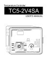
Temperature Controller
TC5-2N6FA
USER'S MANUAL
TABLE OF CONTENTS
TC5-2N6FA
Page
TABLE OF CONTENTS ................................................................ 2
PRECAUTIONS ........................................................................... 3
FEATURES ................................................................................. 4
LOCATION OF THE CONTROLS ................................................... 6
Controller Status LEDS........................................................... 7
Internal Switches .................................................................. 7
INSTALLATION .......................................................................... 8
Mounting Instructions ............................................................ 8
Connections .......................................................................... 8
Motor Types ......................................................................... 9
Temperature Probes ............................................................ 10
CHANGING THE PARAMETER SETTINGS ................................... 12
Using the Display ................................................................. 12
Locking the Parameter Settings ............................................ 13
TEMPERATURE SETTINGS ........................................................ 14
Temperature Units............................................................... 14
Viewing Temperatures ......................................................... 14
Temperature Set Point ......................................................... 17
Temperature Ramp .............................................................. 18
VENTILATION SETTINGS .......................................................... 22
Cooling Operation ................................................................ 22
Minimum Ventilation Cycle ................................................... 25
Minimum Ventilation Cycle Settings ...................................... 25
Humidity Compensation ........................................................ 27
Minimum Ventilation Speed Ramp ......................................... 30
Differential Settings ............................................................. 34
De-icing of Stage 2 Fans ...................................................... 37
Mist Cooling ....................................................................... 39
NATURAL VENTILATION .......................................................... 42
Principle of Operation .......................................................... 42
Settings ............................................................................. 44
HEATER SETTINGS ................................................................... 48
ALARM SETTINGS ................................................................... 52
TEST MODE ............................................................................. 54
TROUBLESHOOTING GUIDE ...................................................... 55
TECHNICAL SPECIFICATIONS ................................................... 59
FACTORY SETTINGS ................................................................ 60
MEMORY CARD ....................................................................... 61
GLOSSARY ............................................................................. 64
2
TC5-2N6FA rev.01
TC5-2N6FA
PRECAUTIONS
We strongly recommend installing supplementary natural ventilation as well as a back-up thermostat on at least one cooling
stage (refer to the wiring diagram enclosed with this user's
manual to connect the thermostat).
Although fuses at the input and outputs of the controller
protect its circuits in case of an overload or overvoltage,
we recommend installing an additional protection device on
the controller's supply circuit.
The room temperature where the controller is located MUST
ALWAYS REMAIN BETWEEN 32°F AND 104°F (0°C TO
40°C).
To avoid exposing the controller to harmful gases or excessive humidity, it is preferable to install it in a corridor.
DO NOT SPRAY WATER ON THE CONTROLLER
FOR CUSTOMER USE
Enter the serial number located on the
side of the controller below for future
reference.
Model number:
Serial number:
TC5-2N6FA
TC5-2N6FA rev.01
3
TC5-2N6FA
FEATURES
The TC5-2N6FA is an electronic device used for environmental control in
livestock buildings. It allows the user to maintain a specified target temperature by controlling the operation of ventilation and heating equipment. Two stages of variable speed fans, two stages of constant speed
fans, as well as curtains, foggers and heaters can be connected to the
controller.
The main features of the TC5-2N6FA are as follows:
FIVE-DIGIT DISPLAY
A five-digit display provides a high level of accuracy, allowing the user to
specify a temperature to within one tenth of a degree (in Fahrenheit or
Celsius units).
PILOT LIGHTS
Pilot lights indicating the state of outputs allow the user to monitor the
operation of the system without having to enter the building.
MINIMUM VENTILATION CYCLE
When ventilation is not required for cooling, the first stage fans can be
operated either continuously or intermittently to reduce the level of humidity and supply oxygen to the room.
RAMPING FUNCTIONS
Ramping functions provide an automatic adjustment of the set point and
minimum ventilation fan speed over a given period of time.
CHOICE OF TEN MOTOR TYPES
The variation in motor speed resulting from a change in voltage will depend on the make and capacity of the motor. In order to achieve a high
degree of compatibility between controller and motor, the user can choose
from among ten different motor types, thus ensuring that the correct voltage is supplied.
HIGH/LOW TEMPERATURE ALARM OUTPUT
HUMIDITY COMPENSATION
The stage 1 minimum speed can be adjusted automatically as a function
of relative humidity. As humidity increases, the minimum speed of stage
1 fans increases proportionally to compensate for the change.
4
TC5-2N6FA rev.01
TC5-2N6FA
ZONED OR CASCADING HEATERS
FULL-SPEED FAN START-UP
In order to overcome the inertia of the ventilation system components and
de-ice the fan blades in cold weather conditions, the controller supplies
maximum voltage to the variable speed fans during the 2 seconds immediately following each start-up.
DE-ICING CYCLE
A de-icing cycle is provided for de-icing stage 2 variable-speed fans in
cold weather conditions.
FOUR INDEPENDENT TEMPERATURE PROBE INPUTS
Up to four temperature probes can be connected to the controller in order
to obtain a more accurate reading of the average room temperature and a
faster reaction time.
OUTSIDE TEMPERATURE COMPENSATION ON CURTAIN SPEED
Curtain opening and closing times can be decreased as a function of outside temperature.
OVERLOAD AND OVERVOLTAGE PROTECTION
Fuses are installed at the input and outputs of the controller to protect its
circuitry in the case of an overload or overvoltage.
MEMORY CARD:
A memory card is used to create a copy of your controller's parameters.
COMPUTER CONTROL
The controller can be connected to a computer, thus making it possible to
centralize the management of information and diversify control strategies.
CONTROL OF AIR INLET MOVEMENT
If the TC5-2N6FA is used in combination with a PF-6 controller, the
movement of the air inlets can be coordinated with the operation of the
fans using a potentiometer located on the panel drive. This allows the air
inlets to be adjusted correctly, without the influence of uncontrollable
factors such as wind or air from adjoining rooms.
TEST MODE
A test mode allows you to simulate temperature changes and verify controller performance.
TC5-2N6FA rev.01
5
TC5-2N6FA
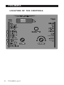
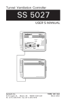
LOCATION OF THE CONTROLS
MAIN
MENU
6
TC5-2N6FA rev.01
DIGITAL
DISPLAY
SCREEN
STATUS
LEDS
TC5-2N6FA
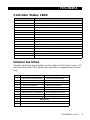
Controller Status LEDS
LED
MEANING
VARIABLE STAGE 1
Turns on when variable stage 1 fans are on.
VARIABLE STAGE 2
Turns on when variable stage 2 fans are on.
STAGE 3
Turns on when stage 3 is on.
STAGE 4
Turns on when stage 4 is on.
MIST
Turns on when the mist output is on.
CURTAIN 1 OPEN
Turns on when curtain 1 opens.
CURTAIN 1 CLOSE
Turns on when curtain 1 closes.
CURTAIN 2 OPEN
Turns on when curtain 2 opens.
CURTAIN 2 CLOSE
Turns on when curtain 2 closes.
HEATER 1
Turns on when heating output 1 is on.
HEATER 2
Turns on when heating output 2 is on.
RH COMPENSATION
Turns on when a RH compensation function is on.
TEMP RAMP
Turns on when the temperature ramp function is activated.
MIN SPEED RAMP
Turns on when the minimum speed ramp function is activated.
PROBE DEFECT
Turns on when a probe is defective.
ALARM
Turns on when an alarm condition is detected.
Internal Switches
Internal switches are located on the inside of the front cover. All
switches are set to OFF when the controller is shipped from the factory,
#
OFF
ON
1
UNLOCKED PARAMETERS
LOCKED PARAMETERS
2
FAHRENHEIT DEGREES
CELSIUS DEGREES
3
PROBE 2 DISABLED
PROBE 2 ENABLED
4
PROBE 3 DISABLED
PROBE 3 ENABLED
5
PROBE 4 DISABLED
PROBE 4 ENABLED
6
2 HEATERS & 0 MIST
1 HEATER & 1 MIST
7
ADJUSTABLE HYSTERESIS
FIX HYSTERESIS OF 2.0°F
8
CASCADING HEATERS
ZONED HEATERS
9
DE-ICING DISABLED
10
DE-ICING ENABLED
RESERVED
11
RESERVED
12
SWITCH FROM OFF TO ON TO ACCES THE TRANSFER MENU
TC5-2N6FA rev.01
7
TC5-2N6FA
INSTALLATION
Mounting Instructions
Open the latch and lift the cover. Remove the black caps located on
each of the four mounting holes. Mount the enclosure on the wall
using four screws. Be sure the electrical knockouts are at the bottom
of the enclosure in order to prevent water from entering the controller. Insert the screws in the mounting holes and tighten. Fasten the
four black caps provided with the controller onto the four mounting
holes. The enclosure must be mounted in a location that will allow the
cover to be completely opened right up against the wall.
Connections
To connect the controller, refer to the wiring diagram enclosed with
this user's manual.
Set the voltage switch to the appropriate voltage.
Use the electrical knockouts provided at the bottom of the
enclosure. Do not make additional holes in the enclosure,
particularly on the side of the enclosure when using a computer communications module.
It may be necessary to install a transformer in order to supply the appropriate voltage to the heating unit.
ALARM CONNECTION: There are two types of alarms on the market. One type activates when current is cut off at its input, whereas
the other activates when current is supplied at its input. For an alarm
of the first type, use the NO terminal as shown on the wiring diagram. For an alarm of the second type, use the NC terminal.
!
WARNING
8
ALL WIRING MUST BE DONE BY AN AUTHORIZED ELECTRICIAN AND MUST COMPLY WITH APPLICABLE CODES, LAWS
AND REGULATIONS. BE SURE POWER IS OFF BEFORE DOING
ANY WIRING TO AVOID ELECTRICAL SHOCKS AND EQUIPMENT DAMAGE.
TC5-2N6FA rev.01
TC5-2N6FA
Motor Types
The relationship between the voltage supplied to a motor and its
operating speed is described by a motor curve. This curve varies
with the make and capacity of the motor. The various motors available in the industry have been divided into ten categories and the
controller has been programmed with a different motor curve for
each of these categories. To ensure that the controller supplies the
correct voltages, an appropriate curve must be selected for stage 1
and stage 2 according to the type of fan motors used.
Selecting a Motor Type for Stage 1 and Stage 2
1
Refer to the list of motors enclosed with this user's to choose the
proper motor type.
•
Set the function to STAGE 1 MOTOR TYPE or to STAGE 2
MOTOR TYPE. The motor type of the selected stage is displayed, alternating with the letters "tYPE".
•
Press the push-button once. The motor type flashes.
•
Use the adjustment knob to adjust the motor type to the
desired value.
•
Press the push-button once again to validate the new value.
TC5-2N6FA rev.01
9
TC5-2N6FA
Temperature Probes
Connecting the Probes
1
The controller is supplied with one temperature probe connected to
input # 1. Up to three additional probes can be connected to the
controller in order to obtain a more accurate reading of the average
room temperature and a faster reaction time.
•
Use inputs # 2, 3 and 4 to connect additional probes, as
shown on the wiring diagram enclosed.
CAUTION: Probes operate at low voltage and are isolated from the
supply. Be sure that probe cables remain isolated from all high voltage sources. In particular, do not route the probe cables through the
same electrical knockout as other cables. Do not connect the shield
from the probe cable to a terminal or a ground.
Switches are used to activate or deactivate the additional probes
connected to the controller.
•
Activate each additional probe by setting
the appropriate switch to ON:
ON
OFF
-
Switch # 3 activates the probe connected
to input # 2.
-
Switch # 4 activates the probe connected
to input # 3.
-
Switch # 5 activates the probe connected
to input # 4.
10 TC5-2N6FA rev.01
TC5-2N6FA
Extending the Probes
2
Each probe can be extended up to 500 feet (150 meters). To
extend a probe:
•
Use a shielded cable of outside diameter between 0.245
and 0.260 in (6.22 and 6.60 mm) (the cable dimensions
should not be under 18 AWG) to ensure the cable entry
is liquid tight. Do not ground the shielding.
•
It is preferable to solder the cable joint to ensure a proper
contact between the two cables.
CAUTION: Do not run probe cables next to other power cables.
When crossing over other cables, cross at 90°.
Defective Probes
3
If a defective probe is detected, the Defective Probe Pilot Light
turns on. The room temperature shown on the display corresponds
to the average temperature measured by the probes in working
condition.
To identify the defective probe:
•
Set the function to PROBE TEMP / MIN / MAX. If the
probe connected to input # 1 is not defective, the letters "PR1" are displayed, alternating with the on/off
state of the probe and the temperature measured by
the probe. If the probe is defective, the letters "PR1"
are displayed, alternating with the state of the probe
and the letter "P".
•
Press the push-button to step to the following probe.
•
Proceed as explained above to make sure all probes are
in working order.
TC5-2N6FA rev.01
11
TC5-2N6FA
CHANGING THE PARAMETER SETTINGS
Using the Display
Flashing Values:
The display will flash in certain cases
and not in others. The flashing indicates that the value shown can be
adjusted. A value that is not flashing
cannot be adjusted.
Relative and Absolute Values:
Some parameter adjustments are displayed both as a relative value
and an absolute temperature. This applies all heating and cooling
differentials, the mist differential and the heater offset. The parameter is first displayed as a relative value. The corresponding
absolute temperature is displayed after six seconds if no action is
taken by the user. The absolute value is the temperature at which
the stage turns on (except in the case of the heater and mist
offsets where the value displayed is the temperature at which
the stage turns off). If the user turns the adjustment knob, the
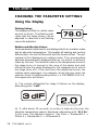
relative value reappears. For example, when the user turns the
selection knob to a differential position, i.e. DIFFERENTIALS 3-4,
the sequence is as follows:
(i) The current differential for stage 3 flashes on the display,
alternating with "3 dIF".
(ii) If, after about 10 seconds, no action is taken by the user, the
absolute temperature value is displayed, alternating with "St 3 On".
In this case, the absolute value is: Set Point + Bandwidth 1 +
Offset 2 + Bandwidth 2 + Differential 3.
12 TC5-2N6FA rev.01
TC5-2N6FA
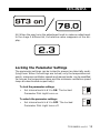
(iii) When the user turns the adjustment knob to make an adjustment
to the stage 3 differential, the relative value reappears on the display.
Locking the Parameter Settings
The parameter settings can be locked to prevent accidentally modifying them. When the settings are locked, only the temperature set
points, minimum ventilation speeds and manual mode can be modified
(as long as the temperature ramp and the minimum ventilation speed
ramp are deactivated respectively).
To lock the parameter settings:
•
ON
Set internal switch # 1 to ON. The Locked
Parameter Pilot Light turns on.
To unlock the parameter settings:
•
OFF
ON
Set internal switch # 1 to OFF. The Locked
Parameter Pilot Light turns off.
OFF
TC5-2N6FA rev.01
13
TC5-2N6FA
TEMPERATURE SETTINGS
Temperature Units
Temperatures can be displayed in either Celsius or Fahrenheit units
•
Set internal switch # 2 to the desired position:
ON
ON: to display temperatures in Celsius units.
OFF: to display temperatures in Fahrenheit units.
OFF
2
Viewing Temperatures
Viewing the Room Temperature
1
The room temperature is the average value of all temperatures
measured by activated probes in proper operating condition.
•
2
•
Set the function to ROOM TEMP MIN / MAX. The average room temperature is displayed.
Viewing the Outside Temperature
Set selection knob to OUTSIDE TEMPERATURE. The outside temperature is displayed.
14 TC5-2N6FA rev.01
TC5-2N6FA
3
Viewing Probe Temperatures
The controller can display probe temperatures individually. Probes
can also be turned on or off to control the temperature in different
parts of the building.
•
Set the function to PROBE TEMP / MIN / MAX. The temperature reading of probe 1 is displayed, alternating with the
letters "Pr 1" and the on/off state of the probe.
•
For each additional probe, press the push-button. The temperature reading of probe x is displayed, alternating with the
letters "Pr x" and the on/off state of the probe, etc.
Viewing Min/Max Temperatures
4
Follow this procedure to see the lowest and highest room temperature values that have been recorded since the last reset.
•
Set the function to ROOM TEMP MIN / MAX or OUTSIDE
TEMP/SET POINT. The corresponding temperature is displayed.
•
Turn the adjustment knob clockwise by one notch. The maximum room temperature is displayed, alternating with the letters "Hi".
•
Turn the adjustment knob counterclockwise one notch. The
room temperature is displayed once again.
•
Turn the adjustment knob counterclockwise one notch further. The minimum room temperature flashes on the display,
alternating with the letters "Lo". If any minimum or maximum temperature reading is out of range, the controller displays the letter "P" instead of displaying a temperature.
NOTE: If you let the display flash for more than 10 seconds, the
controller resets the min and max temperatures currently in memory
(the display stops flashing to indicate the reset has been done).
TC5-2N6FA rev.01
15
TC5-2N6FA
Viewing Min/Max Probe Temperatures
5
Follow this procedure to see the lowest and highest temperature readings that have been recorded by each probe since the last reset.
•
Set the function to PROBE TEMP / MIN / MAX. The temperature reading of probe 1 is displayed, alternating with the
letters "Pr 1" and the on/off state of the probe.
•
Turn the adjustment knob clockwise by one notch. The maximum temperature of probe 1 is displayed, alternating with
the letters "Pr1 Hi".
•
Turn the adjustment knob counterclockwise one notch. The
current temperature of probe 1 is displayed once again.
•
Turn the adjustment knob counterclockwise one notch further. The minimum temperature of probe 1 flashes on the
display, alternating with the letters "Pr1 Lo".
•
Turn the adjustment knob clockwise by one notch. The current temperature of probe 1 is displayed once again.
•
Press the push-button to select another probe then proceed
as explained above to see the minimum and maximum temperature readings of the desired probe.
NOTE: If you let the display flash for more than 10 seconds, the
controller resets the minimum and maximum temperatures of the
selected probe (the display stops flashing to indicate that the reset
has been done).
16 TC5-2N6FA rev.01
TC5-2N6FA
Temperature Set Point
The temperature set point is the target room temperature. It can be
adjusted between 0.0°F and 99.0°F (-17.8°C and 37.7°C).
Adjusting the Temperature Set Point
•
Set the function to SET POINT/TEMP RAMP. The current
set point flashes on the display.
•
Use the adjustment knob to adjust the set point to the desired value.
NOTE: The temperature set point can only be adjusted while the
temperature ramp is deactivated (see following section).
TC5-2N6FA rev.01
17
TC5-2N6FA
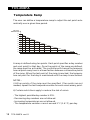
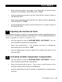
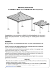
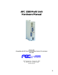
Temperature Ramp
The user can define a temperature ramp to adjust the set point automatically over a given time period.
SET POINT
TEMPERATURE
T° 1
T° 2
T° 3
T° 4
T° 5
T° 6
T°7
T°8
T° 9
T° 10
DAY 4 DAY 15 DAY 21
DAY 30
DAY 36
DAY 45
DAY 55
DAY70
DAY 80
DAY 100
DAYS
A ramp is defined using ten points. Each point specifies a day number
and a set point for that day. Once the points of the ramp are defined,
the ramp must be activated. The controller will change the temperature set point every hour in a linear fashion between consecutive points
of the ramp. When the last point of the ramp is reached, the temperature set point for that day is maintained until the ramp is reactivated.
NOTES :
i) All ten points of the ramp must be specified. If ten points are not
needed, repeat the last temperature value for each unnecessary point.
ii) Certain restrictions apply to reduce the risk of errors:
- The highest possible day number is 255.
- Decreasing day numbers are not allowed.
- Increasing temperatures are not allowed.
- The temperature variation cannot exceed 3°F (1.6°C) per day.
18 TC5-2N6FA rev.01
TC5-2N6FA
Specifying the Ramp
1
The points of the ramp can only be modified while the ramp is disabled. Refer to the 4th section of this chapter to disable the ramp.
•
Set the function to SET POINT/TEMP RAMP. The current
temperature set point flashes on the display – the value does
not flash if the ramp is activated. Refer to the 4th section of
this chapter to disable the ramp.
Repeat the following steps for each of the ten points (point 0
to point 9):
•
Press the push-button. The day number of the first point of
the ramp (point 0) is displayed "d0 x" (where "x" is the day
number).
•
Using the adjustment knob, set the day number of the first
point of the ramp to the desired value.
•
Press the push-button once again. The temperature set point
associated with the first point of the ramp (point 0) is displayed "t0".
•
Using the adjustment knob, adjust the set point of the first
point of the ramp to the desired value.
Once all points of the ramp are defined, activate the ramp as explained below.
TC5-2N6FA rev.01
19
TC5-2N6FA
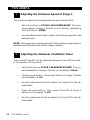
Activating the Temperature Ramp
2
If you have just finished specifying the points on the ramp:
•
Press the push-button once again. The word OFF flashes on
the display.
•
Turn the adjustment knob clockwise one notch. The word
ON flashes on the display and the Temperature Ramp Pilot
Light turns on, indicating that the temperature ramp is now
activated.
If you have previously defined the points on the ramp:
•
Set the function to SET POINT/TEMP RAMP. The current
temperature set point flashes on the display.
•
Press the push-button to display all points of the ramp until
the word OFF appears (twenty-one clicks).
•
Turn the adjustment knob clockwise one notch. The word
ON flashes on the display and the Temperature Ramp Pilot
Light is lit, indicating that the temperature ramp is now activated.
20 TC5-2N6FA rev.01
TC5-2N6FA
Adjusting the Day Number
3
The current day number can be adjusted in order to move forward or
backward on both ramps (temperature and minimum ventilation speed
ramps) at the same time. Note that the current day is set to "OFF" if
no ramp function is enabled.
•
Set the function to CURRENT RAMPING DAY. The current
day number is displayed, alternating with the letters "day".
•
Use the adjustment knob to set the day number to the desired value.
Deactivating the Temperature Ramp
4
•
Set the function to SET POINT/TEMP RAMP. The current
temperature set point is displayed.
•
Press the push-button to display the points of the ramp actually defined until the word ON appears (twenty-one clicks).
•
Turn the adjustment knob counterclockwise one notch. The
word OFF flashes on the display and the Temperature Ramp
Pilot Light turns off indicating that the temperature ramp is
now deactivated.
TC5-2N6FA rev.01
21
TC5-2N6FA
VENTILATION SETTINGS
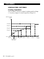
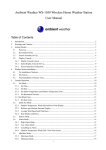
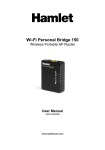
Cooling Operation
The TC5-2N6FA controls two stages of variable-speed fans (Stage
1 - 2) and two stages of constant-speed fans (Stage 3-4).
VENTILATION
LEVEL
STAGE 4
STAGE 3
STAGE 2
STAGE 1
Min.Ventilation
Cycle
Bandw. Offset
Stage1 Stage2
Temperature
Set Point
22 TC5-2N6FA rev.01
Bandw.
Stage2
Diff.
Stage3
Diff.
Stage4
Room
Temp.
TC5-2N6FA
IF THE ROOM TEMPERATURE RISES:
•
When room temperature < Set Point, stage 1 fans run at
minimum speed according to the minimum ventilation cycle.
•
At Set Point: stage 1 fans stop operating according to the
minimum ventilation cycle and increase in speed as the room
temperature rises.
•
At Set Point + Bandwidth 1: stage 1 fans reach full speed.
•
At Set Point + Bandwidth 1 + Stage 2 Offset: stage 2 fans
start running at their minimum speed.
•
At Set Point + Bandwidth 1 + Stage 2 Offset + Bandwidth
2: stage 2 fans reach full speed.
•
At Set Point + Bandwidth 1 + Stage 2 Offset + Bandwidth
2 + Diff. 3: stage 3 fans start running.
•
At Set Point + Bandwidth 1 + Stage 2 Offset + Bandwidth
2 + Diff. 3 + Diff. 4: stage 4 fans start running.
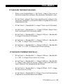
IF THE ROOM TEMPERATURE FALLS*:
•
At Set Point + Bandwidth 1 + Stage 2 Offset + Bandwidth
2 + Diff. 3: stage 4 fans return to a stop;
•
At Set Point + Bandwidth 1 + Stage 2 Offset + Bandwidth
2: stage 3 fans return to a stop; stage 2 fans start decreasing in speed as the temperature decreases.
•
At Set Point + Bandwidth 1 + Stage 2 Offset - 0.3°F: stage
2 fans return to a stop.
•
At Set Point + Bandwidth 1: Stage 1 fans start decreasing
in speed as the temperature decreases.
TC5-2N6FA rev.01
23
TC5-2N6FA
•
At Set Point: Stage 1 fans reach minimum speed.
•
Below the Set Point: stage 1 fans stop operating continuously and operate according to the minimum ventilation cycle
at minimum speed.
* USING A FIX HYSTERESIS ON VENTILATION STAGES 3-4:
This function allows deactivating stages 3 and 4 when the room temperature decreases of 2°F (1.1°C) below their respective differential. Set the internal switch #7 to ON to activate this function.
Ventilation
Level
stage 4
stage 3
stage 2
Hysteresis
2°F
Bandwidth
Stage 2
24 TC5-2N6FA rev.01
Differential
Stage 3
Hysteresis
2°F
Differential
Stage 4
Room T°
TC5-2N6FA
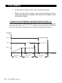
Minimum Ventilation Cycle
When the room temperature is below the set point, the fans of stage 1
operate according to the minimum ventilation cycle. Running the fans
even though ventilation is not required for a cooling purpose is useful
to reduce humidity levels and supply oxygen to the room. It also
prevents the fans from freezing in winter.
TIME ON
STAGE 1
STAGE 1 —
MIN. SPEED
OFF
TIME OFF
STAGE 1
During the Time On, stage 1 fans run at their minimum speed and
the pilot light of stage 1 is lit; during the Time Off, the fans return to
a stop and the pilot light turns off. Note that the minimum speed of
stage 1 can automatically be adjusted over time with a ramp (see
below).
NOTE: The controller supplies maximum voltage to the variable-speed
fans for 2 seconds immediately following each start-up.
Minimum Ventilation Cycle Settings
1. To run the fans continuously at minimum speed, set the Time
Off to zero and Time On to any value other than zero.
2. To stop the fans, set the Time On to zero and Time Off to
any value.
3. To run the fans intermittently, set the Time On to the desired running time and Time Off to the desired off time.
TC5-2N6FA rev.01
25
TC5-2N6FA
Adjusting the Minimum Speed of Stage 1
1
The minimum speed can be adjusted between 10 and 100%.
•
Set the function to STAGE 1 MIN SPEED/RAMP. The minimum speed of stage 1 flashes on the display, alternating
with the letters "SPEEd".
•
Use the adjustment knob to adjust the minimum speed to the
desired value.
NOTE: This speed can only be adjusted if the minimum speed ramp is
disabled (see Minimum Ventilation Ramp chapter).
Adjusting the Minimum Ventilation Timer
2
Time on and Time Off can be adjusted between 0 and 900 seconds,
in increments of 15 seconds.
•
Set the function to STAGE 1 BANDWIDTH/TIMER. The current bandwidth of stage 1 flashes on the display "BAnd".
•
Press the push-button. The current Time On of stage 1 flashes
on the display "t. On".
•
Use the adjustment knob to adjust the Time On to the desired value.
•
Press the push-button. The current Time Off of stage 1
flashes on the display "t. Off".
•
Use the adjustment knob to adjust the Time Off to the desired value.
26 TC5-2N6FA rev.01
TC5-2N6FA
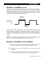
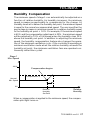
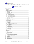
Humidity Compensation
The minimum speed of stage 1 can automatically be adjusted as a
function of relative humidity. As humidity increases, the minimum
speed increases proportionally to compensate for the change. At
humidity levels at or below the humidity set point, the minimum speed
is equal to the normal uncompensated speed. The user specifies the
percentage increase in minimum speed for a relative humidity equal
to the humidity set point + 10%. For example, if the minimum speed
is 40% and the compensation adjustment is 30%, the minimum speed
will be adjusted to 70% of full speed when the humidity rises 10%
above the humidity set point. In addition to adjusting the minimum
speed, the humidity compensation feature also changes the operation of the minimum ventilation cycle: if the controller is operating in
minimum ventilation mode when the relative humidity exceeds the
humidity set point, the minimum ventilation fans are operated continuously rather than cycled.
Stage 1
Min. Speed
100%
Compensation begins
Compensation %
Normal
Min. Speed
10 %
0%
Relative
Humidity
Set Point
Relative
Humidity
When a compensation is applied to the minimum speed, the compensation pilot light turns on.
TC5-2N6FA rev.01
27
TC5-2N6FA
Viewing the Relative Humidity
1
The relative humidity is expressed as a percentage.
•
Set the function to RELATIVE HUMIDITY MIN/MAX. The
current relative humidity is displayed.
•
Turn the adjustment knob clockwise by one notch. The maximum humidity reading flashes on the display, alternating with
the letters "rH Hi".
•
Turn the adjustment knob counterclockwise one notch the
current humidity level is displayed once again.
•
Turn the adjustment knob counterclockwise one notch further. The minimum humidity reading flashes on the display,
alternating with the letters "rH Lo".
NOTE: If you let the display flash for more than 10 seconds when the
maximum or minimum humidity is displayed, the controller resets the
minimum and maximum humidity values currently in memory (the
display stops flashing to indicate that the reset has been done).
Adjusting the Relative Humidity Set Point
2
When the relative humidity exceeds the humidity set point, the minimum speed of stage 1 fans is increased by a proportional amount to
compensate for the increase in humidity. Note that the humidity compensation feature must be activated for this to work.
•
Set the function to STAGE 1 RH COMPENSATION. The relative humidity set point is displayed alternating with the letters "Set".
•
Use the adjustment knob to adjust the set point to the desired value.
28 TC5-2N6FA rev.01
TC5-2N6FA
Adjusting the Minimum Speed Compensation
3
This is the increase in the minimum speed for a relative humidity
equal to the humidity set point + 10%. It ranges from 0 to 100%.
•
Set the function to STAGE 1 RH COMPENSATION. The relative humidity set point is displayed alternating with the letters "Set".
•
Press the push-button. The current minimum speed compensation is displayed, alternating with the letters "SPEEd".
•
Use the adjustment knob to adjust the minimum speed compensation to the desired value.
Activating/Deactivating Humidity Compensation
4
•
Set the function to STAGE 1 RH COMPENSATION. The relative humidity set point is displayed alternating with the letters "Set".
•
Press the push-button twice. The current on/off state of humidity compensation flashes on the display.
•
Use the adjustment knob to adjust the on/off state to the
desired value.
TC5-2N6FA rev.01
29
TC5-2N6FA
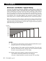
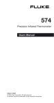
Minimum Ventilation Speed Ramp
The user can define a minimum ventilation speed ramp to adjust the
minimum speed of stage 1 automatically over a given time period. A
ramp is defined by ten points and each point specifies a day number
and a fan speed for that day. Once the points are defined, the minimum speed ramp must be activated. When the minimum speed ramp
is activated, the controller adjusts the minimum speed of state 1
fans every hour in a linear fashion between two consecutive points.
When the last point of the ramp is reached, the ramp is deactivated.
The controller maintains the minimum speed specified for this point
until the ramp is reactivated or until a new single minimum speed is
specified using the first method.
STAGE 1 MIN.
SPEED (%)
SPEED 10
SPEED 9
SPEED 8
SPEED 7
SPEED 6
SPEED 5
SPEED 4
SPEED 3
SPEED 2
SPEED 1
DAY 1
DAY 5
DAY 10
DAY 17
DAY 25
DAY 35
DAY 40
DAY 60
DAY 80
DAY 100
DAYS
NOTES:
i) The minimum speed ramp must be deactivated before specifying the points on the ramp (see below).
ii)
All ten points of the ramp must be specified. If you do not
need ten different points, repeat your last minimum speed
for each unnecessary point of the ramp.
iii) Certain restrictions apply to reduce the risk of errors:
• decreasing minimum speeds are not allowed.
• the min. speed variation cannot exceed 10% per day.
30 TC5-2N6FA rev.01
TC5-2N6FA
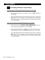
1
Specifying the Minimum Speed Ramp
The points of the ramp can only be modified while the ramp is
disabled. Refer to the 4th section of this chapter to disable the
ramp.
•
Set the function to STAGE 1 MIN SPEED/RAMP. The
current minimum speed of stage 1 flashes on the display
– the value does not flash if the ramp is activated. Refer
to the 4th section of this chapter to disable the ramp.
Repeat the following steps for each of the ten points
(point 0 to point 9):
•
Press the push-button. A day number is displayed, alternating with the word "d0 x" (where "x" is the day number).
•
Using the adjustment knob, set the day number of the
first point of the ramp to the desired value.
•
Press the push-button once again. The minimum speed of
the first point (point 0) is displayed "P0 x" where x represents the speed.
•
Use the adjustment knob to adjust the minimum speed of
the first point of the ramp to the desired value.
TC5-2N6FA rev.01
31
TC5-2N6FA
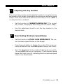
Activating Minimum Speed Ramp
2
If you have just finished specifying the points on the ramp:
•
Press the push-button once again. The word OFF flashes on
the display.
•
Turn the adjustment knob clockwise by one notch. The word
ON flashes on the display and the Minimum Speed Ramp
Pilot Light turns on, indicating that the minimum speed ramp
is now activated.
If you have previously specified the points on the ramp:
•
Set the function to STAGE 1 MIN SPEED/RAMP. The current minimum speed flashes on the display.
•
Press the push-button to display the points of the ramp currently defined until the word OFF appears (twenty-one clicks).
•
Turn the adjustment knob clockwise by one notch. The word
ON flashes on the display and the Minimum Speed Ramp
Pilot Light turns on, indicating that the minimum speed ramp
is now activated.
32 TC5-2N6FA rev.01
TC5-2N6FA
Adjusting the Day Number
3
The current day number can be adjusted in order to move forward or
backward on both ramps (temperature and minimum ventilation speed
ramps) at the same time. Note that the current day is set to "OFF" if
no ramp function is enabled.
•
Set the function to CURRENT RAMPING DAY. The current
day number is displayed, alternating with the letters "day".
•
Use the adjustment knob to set the day number to the
desired value.
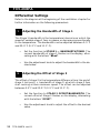
4
Deactivating Minimum Speed Ramp
•
Set the function to STAGE 1 MIN SPEED/RAMP. The current minimum speed flashes on the display.
•
Press the push-button to display the points of the ramp currently defined until the word ON appears (twenty-one clicks).
•
Turn the adjustment knob counterclockwise by one notch.
The word OFF flashes on the display. The Minimum Speed
Ramp Pilot Light turns off, indicating that the minimum speed
ramp is now deactivated.
TC5-2N6FA rev.01
33
TC5-2N6FA
Differential Settings
Refer to the diagram at the beginning of the ventilation chapter for
further information on the following parameters.
Adjusting the Bandwidth of Stage 1
1
The Stage 1 bandwidth is the temperature interval over which the
speed of variable stage 1 fans increases or decreases proportionally
to the temperature. The bandwidth can be adjusted between 0.5°F
and 20.0°F (0.3°C and 11.1°C).
•
Set the function to STAGE 1 — BANDWIDTH/TIMER. The
current bandwidth of stage 1 flashes on the display, alternating with the letters "BAnd".
•
Use the adjustment knob to adjust the bandwidth to the desired value.
Adjusting the Offset of Stage 2
2
The offset of stage 2 is the temperature difference from the end of
stage 1 (set point + bandwidth of stage 1) at which stage 2 fans
start running at their minimum speed. The offset can be adjusted
between 0.5°F and 20.0°F (0.5°C and 11.1°C).
•
Set the function to STAGE 2 OFFSET/BANDWIDTH. The
current offset of Stage 2 flashes on the display, alternating
with the letters "OFSET".
•
Use the adjustment knob to adjust the offset to the desired
value.
34 TC5-2N6FA rev.01
TC5-2N6FA
Adjusting the Bandwidth of Stage 2
3
The bandwidth of Stage 2 is the temperature interval over which the
speed of variable stage 2 fans increases or decreases proportionally
to the temperature. The bandwidth can be adjusted between 0.5°F
and 20.0°F (0.3°C and 11.1°C).
•
Set the function to STAGE 2 OFFSET/BANDWIDTH. The current offset of Stage 2 flashes on the display, alternating with
the letters "OFSET".
•
Press the push-button. The current bandwidth of Stage 2 is
displayed, alternating with the letters "BAnd".
•
Use the adjustment knob to adjust the bandwidth to the desired value.
Adjusting the Minimum Speed of Stage 2
4
The minimum speed of stage 2 fans can be adjusted between 10%
and 100%.
•
Set the function to STAGE 2 MIN SPEED. The minimum speed
of stage 2 flashes on the display, alternating with the letters
"SPEEd".
•
Use the adjustment knob to adjust the minimum speed to the
desired value.
TC5-2N6FA rev.01
35
TC5-2N6FA
Adjusting the Differentials of Stages 3-4
5
The differential of stage 3 is the temperature difference from the
moment stage 2 fans reach full speed and the moment stage 3 fans
start; the differential of stage 4 is the temperature difference above
the start temperature of stage 3 at which stage 4 starts. Stage 3-4
differentials can be adjusted between 0.5°F and 20.0°F (0.3°C and
11.1°C).
•
Set the function to STAGES 3-4 DIFFERENTIAL. The current differential of Stage 3 flashes on the display, alternating with the letters "3 diF".
•
Use the adjustment knob to adjust it to the desired value.
•
Press the push-button. The current differential of Stage 4
flashes on the display, alternating with the letters "4 diF".
•
Use the adjustment knob to adjust it to the desired value.
36 TC5-2N6FA rev.01
TC5-2N6FA
De-icing of Stage 2 Fans
Stage 2 fans can automatically be de-iced in cold weather conditions. When a de-icing cycle starts, Stage 1 fans are stopped then
stage 2 fans start running at full speed for 2 seconds. Stage 2 fans
then run at the minimum speed of stage 2 during the de-icing time.
Once the de-icing time has elapsed, stage 2 fans stop and the operation of stage 1 is resumed. Set internal switch #9 to ON to activate
this function.
ON
OFF
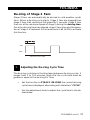
DE-ICING CYCLE TIME
Adjusting the De-icing Cycle Time
1
The de-icing cycle time is the time lapse between de-icing cycles. It
ranges from 1 to 720 minutes. Note that the cycle time must be
greater or equal to the de-icing On Time.
•
Set the function to STAGE 2 DE-ICING the current de-icing
cycle time is displayed, alternating with the letters "CYCLE".
•
Use the adjustment knob to adjust the cycle time to the desired value.
TC5-2N6FA rev.01
37
TC5-2N6FA
Adjusting the De-icing On Time
2
The de-icing duration ranges from 0 to 900 seconds. Note that the
de-icing On Time must be shorter or equal to the Cycle Time.
•
Set the function to STAGE 2 DE-ICING the current de-icing
cycle time is displayed, alternating with the letters "CYCLE".
•
Press the push-button. The current de-icing time is displayed,
alternating with the letters "t On".
•
Use the adjustment knob to adjust the de-icing time to the
desired value.
38 TC5-2N6FA rev.01
TC5-2N6FA
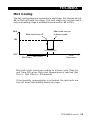
Mist Cooling
The last cooling stage can be used as a mist stage. Set internal switch
#6 to ON to activate this stage. This mist stage can only be used if
only one heating stage is enabled (internal switch #6 to ON).
Mist
Mist units turn off
Mist units turn on
in timer mode
ON
DIFFERENTIAL
OFF
Set Point
Mist Offset
Room
Temperature
Mist units start running according to a timer cycle (Time On
and Time Off) when their start temperature is reached (Set
Point + Mist Offset + Differential).
If the humidity compensation is activated, the mist units are
shut off when the humidity level is too high.
TC5-2N6FA rev.01
39
TC5-2N6FA
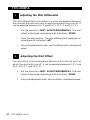
Adjusting the Mist Differential
1
The mist differential is the variation in room temperature between
the moment the mist units turn on and the moment they turn off. It
can be adjusted between 0.5°F and 20.0°F (0.3°C and 11.1°C).
•
Set the function to MIST OFFSET/DIFFERENTIAL. The mist
offset is displayed, alternating with the letters "OFSEt".
•
Press the push-button. The mist differential is displayed, alternating with the letters "dIF",
•
Using the adjustment knob, set the differential to the desired
value.
Adjusting the Mist Offset
2
The mist offset is the temperature difference from the set point at
which the mist units turn off. It can be adjusted between 0.5°F and
20.0°F (0.3°C and 11.1°C).
•
Set the function to MIST OFFSET/DIFFERENTIAL. The mist
offset is displayed, alternating with the letters "OFSEt".
•
Using the adjustment knob, set the offset to the desired value.
40 TC5-2N6FA rev.01
TC5-2N6FA
Adjusting the Mist Timer Settings
3
The timer's On Time can be adjusted from 0 to 900 seconds, in increments of 15 seconds; the Off Time can be adjusted from 0 to 60 minutes. To deactivate mist cooling, set the Time On to zero. This parameter is only displayed if mist units are enabled (internal switch #6).
•
Set the function to MIST TIMER. The current Time On for
the mist cycle is displayed, alternating with the letters "t On".
•
Use the adjustment knob to set the Time On to the desired
value (in minutes).
•
Press the push-button The current Time Off for the mist
cycle is displayed, alternating with the letters "t Off".
•
Use the adjustment knob to set the Time Off to the desired
value (in minutes).
Adjusting the Mist Shutoff Set Point
4
The mist shutoff set point is the humidity level above which mist units
are disabled. This parameter is only displayed if mist units are enabled
(internal switch #6). The mist shutoff value ranges from 0 to 100%
of humidity. To disable this function, increase the parameter value
until you reach the word "no".
•
Set the function to MIST RH COMPENSATION. The humidity level above which mist units turn off is displayed, alternating with the letters "rH OFF".
•
Use the adjustment knob to set the humidity level over which
the mist stage stops operating.
TC5-2N6FA rev.01
41
TC5-2N6FA
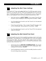
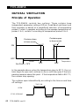
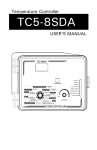
NATURAL VENTILATION
Principle of Operation
The TC5-2N6FA controls two curtains. These curtains have
independent parameter settings (Offset, Dead Band and timer) and
their operation is based on a predefined selection of temperature
probes: Curtain 1 operates according to the average temperature of
probes 1 & 2; curtain 2 according to temperature probes 3 & 4.
Curtains open
in timer mode
Curtains close
in timer mode
0.3oF
0.3oF
ON
OFF
Dead Band
Offset
o
Set Point = 75 F
79°F
Temperature
89oF
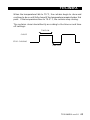
In the example above, when the temperature rises to 89°F, the curtains begin to open and continue to do so until fully open if the temperature remains above this point. If the temperature falls to 88.7°F,
the curtains stop opening.
The curtains open intermittently according to the time on and time
off settings:
TIME ON
OPEN
STOP OPENING
TIME OFF
42 TC5-2N6FA rev.01
TC5-2N6FA
When the temperature falls to 79°F, the curtains begin to close and
continue to do so until fully closed if the temperature remains below this
point. If the temperature rises to 79.3°F, the curtains stop closing.
The curtains close intermittently according to the time on and time
off settings:
TIME ON
CLOSE
STOP CLOSING
TIME OFF
TC5-2N6FA rev.01
43
TC5-2N6FA
CURTAIN OPERATING TIME COMPENSATION
1. Normal Mode (Without Compensation)
The curtains open and close intermittently according to the specified
opening time, closing time and time off, as described on the preceding pages. There is no outside temperature compensation.
2. Progressive Mode (With Compensation)
The controller can use the current outside temperature to adjust the
opening and closing times of the curtains. This feature must be activated from the front panel (see below). An outdoor temperature
probe must be connected to input #5 for this feature to work.
Room Temperature Rises: When the curtains open, the controller
increases TIME ON by 5% for every 1°F (0.6°C) difference between
the outside temperature and the outside Set Point. The TIME OFF is
decreased by the same amount. This is true if the outside temperature is greater than the outside set point.
The higher the outside temperature, the time on increases, causing
the curtains to open faster.
Room Temperature Falls: When the curtains close, the controller
increases TIME ON by 5% for every 1°F (0.6°C) difference between
the outside temperature and the outside Set Point. TIME OFF is decreased by the same amount. This is true if the outside temperature
is lower than the outside set point.
The lower the outside temperature, time on increases, causing the
curtains to close faster.
NOTE: If, after compensation, the time off value is less than or equal
to ten seconds, it is set to zero.
44 TC5-2N6FA rev.01
TC5-2N6FA
Settings
1
Manual Control of the Curtains
•
Set the selection knob to CURTAINS MANUAL MODE. The status
of the manual control mode is displayed for curtain 1.
•
Use the adjustment knob to select the proper manual mode status
for curtain 1:
"1 AUt."
"1 OPn"
"1 CLo"
"1 OFF"
•
to select the automatic control mode;
to manually open curtain 1 (the letters "1 OPn" flash
on the display for 5 seconds then the curtain 1 starts
opening);
to manually close curtain 1 (the letters "1 CLO" flash
on the display for 5 seconds then curtain 1 starts
closing);
to stop the actuator of curtain 1.
Press the push-button to select the manual mode status of curtain 2.
Adjusting the Curtain Offset
2
The offset is the number of degrees, above the set point, at which a curtain
starts closing in timer mode (refer to the previous graph). It can be adjusted
from 0.5 to 20.0°F (0.3 to 11.1°C), must be greater than bandwidth 1
and must be set separately for each curtain.
•
Set the selection knob to CURTAINS — OFFSET/DEAD BAND. The
offset of curtain 1 flashes on the display, alternating with the letters
"1 OFS".
•
Use the adjustment knob to set curtain 1 offset to the desired value.
•
Press the push-button twice. The offset of curtain 2 flashes on
the display, alternating with the letters "2 OFS".
•
Use the adjustment knob to set curtain 2 offset to the desired value.
TC5-2N6FA rev.01
45
TC5-2N6FA
Adjusting the Curtains Dead Band
3
The dead band is the temperature difference between the opening and
closing temperatures of the curtains. It ranges from 0.5°F to 20.0°F (0.3°C
to 11.1°C) and must be adjusted separately for each curtain.
•
Set the selection knob to CURTAINS — OFFSET/DEAD BAND.
The offset of curtain 1 flashes on the display, alternating with the
letters "1 OFS".
•
Press the push-button. The dead band for curtain 1 flashes on the
display, alternating with the letters "1 BND".
•
Use the adjustment knob to set the dead band of curtain 1 to the
desired value.
•
Press the push-button twice. The dead band for curtain 2 flashes
on the display, alternating with the letters "2 BND".
•
Use the adjustment knob to set the dead band of curtain 2 to the
desired value.
Adjusting the Curtain Timer
4
The curtain timer is made of a Time ON and of a Time OFF. The Time ON
ranges from 10 to 900 seconds and the Time OFF from 0 to 900 seconds
and can be adjusted in increments of 5 seconds. The timers must be set
separately for each curtain.
•
Set the selection knob to CURTAINS — TIMER. The Time ON of
curtain 1 timer flashes on the display, alternating with "1 On".
•
Use the adjustment knob to set the Time ON of curtain 1 timer to
the desired value.
•
Press the push-button. The Time OFF of curtain 1 timer is displayed,
alternating with "1 OFF".
•
Use the adjustment knob to set the Time OFF of curatin 1 timer to
the desired value.
46 TC5-2N6FA rev.01
TC5-2N6FA
•
Press the push-button once again. The Time ON of curtain 2 timer
flashes on the display, alternating with "2 On".
•
Use the adjustment knob to set the Time ON of curtain 2 timer to
the desired value.
•
Press the push-button. The Time OFF of curtain 2 timer is displayed,
alternating with "2 OFF".
•
Use the adjustment knob to set the Time OFF of curtain 2 timer to
the desired value.
Adjusting the Outside Set Point
5
The outside set point is used for compensating curtain operating times as
a function of outside temperature (see above). It can be adjusted between
-40.0°F and 99.9°F (-40.0°C and 37.7°C).
•
Set the selection knob to OUTSIDE TEMP / SET POINT. The current outside temperature is displayed.
•
Press the push-button. The outside set point is displayed,
alternating with the letters "SEt".
•
Use the adjustment knob to adjust the outside set point to the
desired value.
Activating Outside Temperature Compensation
6
•
Set the selection knob to OUTSIDE TEMP / SET POINT. The current outside temperature is displayed.
•
Press the push-button twice. The current on/off status of the
outside compensation feature is displayed.
•
Use the adjustment knob to enable or disable the compensation
function.
TC5-2N6FA rev.01
47
TC5-2N6FA
HEATER SETTINGS
The controller can control up to two heating stages. Set internal
switch #6 to “ON” to use one heating stage; set it to “OFF” to use
both heating stages.
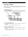
CASCADING HEATERS
When cascading heating is used, the operation of heating stages is
based on the average room temperature (internal switch #8 is OFF).
HEATER 2
TURNS ON
HEATING
OUTPUTS
HEATER 2
TURNS OFF
HEATER 1
TURNS ON
HEATER 2
ON
HEATER 1
TURNS OFF
HEATER 1
ON
OFF
HEATER 2
DIFFERENTIAL
HEATER 1
DIFFERENTIAL
HEATER 1
OFFSET
ROOM T°
SET POINT
If the room temperature rises:
- at Set Point - Heater 1 Offset - Heater 1 Differential: Heater 2
turns off.
- at Set Point - Heater 1 Offset: Heater 1 turns off.
If the room temperature falls:
- at Set Point - Heater 1 Offset - Heater 1 Differential: Heater 1
turns on.
- at Set Point - Heater 1 Offset - Heater 1 Differential - Heater 2
Differential: Heater 2 turns on.
48 TC5-2N6FA rev.01
TC5-2N6FA
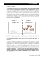
ZONED HEATERS
To configure your system for zoned heaters, set internal switch # 8
to ON. Since the two heater outputs operate independently, different probes are assigned to each output: Probes 1 and 2 are assigned
to Heater 1 and Probes 3 and 4 are assigned to Heater 2. Individual
probes can be turned on or off using the internal switch settings. If
both probes are activated for a given heater, the average temperature from both probes is used; if they are not activated, the heater
uses the room temperature. If only one heater is active, heater 1
uses the room temperature.
ZONE 2
PROBES 3 & 4
NOT USED
MINIMUM HEAT
ZONE 1
PROBES 1 & 2
YOUNG ANIMALS
Both heating zones can have negative and positive heater offsets.
Using a negative offset allows activating the heating output above
the temperature set point; this can be useful to control heat mats for
instance.
To avoid ventilation problems when using zoned heating, a special
protection is built into the device. Suppose the animals are young and
confined to one part of the building (zone 1) while the rest of the
building is heated at a minimum level (zone 2). If the temperature
difference between zones is too high and zone 1 fans operate according to the average temperature for both zones, cooling in zone 1
may be insufficient. A built-in protection will operate the fans according to the probes of the zone with the highest temperature whenever the temperature difference between zones is greater than a
user-defined value.
TC5-2N6FA rev.01
49
TC5-2N6FA
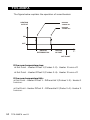
The figure below explains the operation of zoned heaters.
HEATER
TURNS ON
HEATING
OUTPUT
HEATER
TURNS OFF
ON
OFF
HEATER
DIFFERENTIAL
HEATER
OFFSET
T°
SET POINT
If the room temperature rises:
at Set Point - Heater Offset 1 (Probes 1-2): Heater 1 turns off.
at Set Point - Heater Offset 2 (Probes 3-4): Heater 2 turns off.
If the room temperature falls:
at Set Point - Heater Offset 1 - Differential 1 (Probes 1-2): Heater 1
turns on.
at Set Point - Heater Offset 2 - Differential 2 (Probe 3-4): Heater 2
turns on.
50 TC5-2N6FA rev.01
TC5-2N6FA
Adjusting Heater Offsets
1
The heater offset can provide substantial energy savings if correctly
adjusted according to the outside temperature. This offset represents the number of degrees below the set point at which the heating units turn off (see diagram above). The offset of heaters 1 and 2
can be adjusted from -10oF to 20.0oF (-5.6oC to 11.1oC). If the offset is negative, the heating units will turn off at temperatures above
the set point. If cascading heating is used, only Heater 1 offset is
used.
•
Set selection knob to HEATER 1 OFFSET/DIFFERENTIAL or
HEATER 2 OFFSET/DIFFERENTIAL The current heating offset is displayed, alternating with the letters "OFSEt".
•
Use the adjustment knob to adjust the offset to the desired
value.
Adjusting Heater Differentials
2
The heating differential is the temperature difference between the
moment the heating units turn on and the moment they turn off (see
diagram above). It can be adjusted between 0.5°F and 20.0°F (0.3°C
and 11.1°C).
•
Set selection knob to HEATER 1 OFFSET/DIFFERENTIAL or
HEATER 2 OFFSET/DIFFERENTIAL The current heating offset is displayed, alternating with the letters "OFSEt".
•
Press the push-button. The differential is displayed, alternating with the letters "diF".
•
Use the adjustment knob to adjust the differential to the desired value.
TC5-2N6FA rev.01
51
TC5-2N6FA
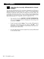
Adjusting the Security Differential for Zoned
Heaters
3
The security differential is the maximum temperature difference
allowed between the heating zones 1 and 2. If the temperature
difference between these zones exceeds the security level, the
controller will make the fans run according to the temperature
perceived in the warmest zone. The security differential can be
adjusted between 0.5°F and 20°F (0.3°C and 11.1°C)
•
Set selection knob to HEATER 2 OFFSET/DIFFERENTIAL
The current heating offset is displayed, alternating with
the letters "OFSEt".
•
Press the push-button twice. The security differential is
displayed, alternating with the letters "2n diF". *This
parameter is only available if zoned heaters are used (i.e.,
internal switch #8 is ON).
•
Use the adjustment knob to adjust the security differential
to the desired value.
52 TC5-2N6FA rev.01
TC5-2N6FA
ALARM SETTINGS
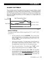
The controller sets off an alarm in the case of a power failure, a fault
in the supply circuit or a high or low temperature. Temperature alarms
are defined according to the set point as shown in the diagram below. The temperature alarm can either be set off if the average temperature exceeds the limits or if the reading of a single probe exceeds the limit.
High Temperature Alarm
Room
Temperature
High Alarm Offset
Set Point
Low Alarm Offset
Time
Alarm Settings
The high and low alarm offsets range from 0.5°F to 40°F (0.3
to 22.2°C).
•
Set the selection knob to ALARMS. The current low
alarm offset flashes on the display, alternating with the
letters "LoAL". Use the adjustment knob to set it to
the desired value.
•
Press the push-button. The high alarm offset flashes on
the display, alternating with the letters "HiAL". Use
the adjustment knob to set it to the desired value.
•
Press the push-button. The alarm type "TyPE" is displayed, alternating with the word "ALL" or "Ind".
•
Use the adjustment knob to select "ALL" for an alarm
to sound when the average temperature exceeds the
defined high or low limits; select "Ind" for alarm to sound
when the reading of an individual probe exceeds the
high or low temperature limits.
TC5-2N6FA rev.01
53
TC5-2N6FA
TEST MODE
A test mode allows you to simulate temperature changes and verify
the performance of your controller. In test mode, the temperature
probe inputs are turned off, allowing to change the temperature used
by the controller to operate the stages. The controller operates as
before using the new temperature settings.
Enable / disable the test mode:
•
Set the function to TEST MODE. The test mode status flashes
on the display.
•
Use the adjustment knob to select the desired test mode
status (On or Off).
Setting the test mode temperature:
•
Once the test mode is enabled, press the push button. The
test mode temperature is displayed, alternating with the letters "tSt".
NOTE: If no user activity is recorded after 4 minutes in test mode,
the controller automatically exits from the test mode.
54 TC5-2N6FA rev.01
TC5-2N6FA
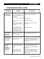
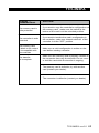
TROUBLESHOOTING GUIDE
PROBLEM
CAUSE
The display
doesn't work.
The circuit breaker on
the service panel is off
or tripped.
Reset the circuit breaker.
The wiring is incorrect.
Fix the wiring.
The input fuse is
open.
Replace the fuse.
The voltage selector
switch is in the wrong
position.
Set the switch to the correct
position.
The display board
interconnect cable is
unplugged from the
power supply board.
Plug the cable.
The display
shows the
letter "P"
Probe # 1 is improperly connected.
Fix the probe's connection.
The Defective
Probe Pilot
Light is on.
One or more probes
are defective.
Follow the procedure described
in DEFECTIVE PROBES to
identify and replace the defective probe.
The display
shows
sudden
variations in
room temperature.
A variation in resistance is induced on a
probe.
Make sure the probes are dry
and move them away from
drafts and sources of radiant
heating.
There is electrical
noise near an extended probe cable.
Do not run probe cables next to
other power cables. When
crossing other power cables,
cross at 90o.
SOLUTION
TC5-2N6FA rev.01
55
TC5-2N6FA
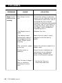
PROBLEM
Stage 1 or 2
fans are not
running.
CAUSE
SOLUTION
The wiring is incorrect.
Correct the wiring. In particular,
make sure two different lines are
connected to each motor: line L1
modulated by the controller
should be combined with another
line (N for 115V or L2 for 230V) to
activate the motor. Also, be sure
the Stage 1 and 2 COMMON is
supplied by line L1.
The Stage's fuse is
open.
Replace the fuse.
The display board
interconnect cable is
not plugged into the
power supply board
properly.
Make sure the cable is firmly
plugged in with the tabs in
place.
The minimum speed
is too low.
Adjust the minimum speed to a
higher value.
The fan motor is
defective.
Check if motor is defective by
connecting it to an alternate
power supply. Replace the
motor if it still doesn't operate.
The On time of stage 1
fans in minimum
ventilation is set to
zero.
56 TC5-2N6FA rev.01
Set the On Time to a
value other than zero.
TC5-2N6FA
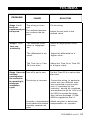
PROBLEM
CAUSE
The wiring is incorStage 1 or 2
rect.
fans run
continuously at
The ambient temperafull speed.
ture is above the set
point.
Stage 1 or 2
fans run
erratically.
SOLUTION
Fix the wiring.
Adjust the set point to the
desired value.
The selected motor
ramp is inappropriate.
Select an appropriate motor
ramp.
The differential is too
small.
Adjust the differential to a
higher value.
The Time On or Time
Off is too short.
Adjust the Time On or Time Off
to a higher value.
Stage 1 fans do Time off is set to zero.
not stop
running when
the controller
is operating in The wiring is incorrect.
minimum
ventilation
cycle.
Set the Time Off to a value other
than zero.
Correct the wiring. In particular,
make sure two different lines
are connected to each motor:
line L1 modulated by the
controller should be combined
with another line (N for 115V or L2
for 230V) to activate the motor.
Also, be sure the stage 1 COMMON is supplied by line L1.
Humidity compensation Adjust set point or deactivate
is activated and relative compensation as required.
humidity exceeds set
point.
TC5-2N6FA rev.01
57
TC5-2N6FA
CAUSE
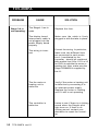
PROBLEM
Stage 3-4 is
not operating.
SOLUTION
The Stage's fuse is
open.
Replace the fuse.
The display board
interconnect cable is
not plugged into the
power supply board
properly.
Make sure the cable is firmly
plugged in with the tabs in place.
The wiring is incorrect.
Correct the wiring. In particular,
make sure two different lines
are connected to each motor:
line L1 modulated by the
controller should be combined
with another line (N for 115V or L2
for 230V) to activate the motor or
heating unit. Also, make sure the
Stage COMMON is supplied by
line L1.
The fan motor or
heating unit is
defective.
Verify if the motor or heating unit
is defective by connecting it to
an alternate power supply.
Replace the motor or heating
unit If it still is not operating.
The controller is
defective.
Listen to see if there is a clicking
sound when the Stage's pilot
light turns on. If there is no
clicking sound, contact your
distributor to repair the controller.
58 TC5-2N6FA rev.01
TC5-2N6FA
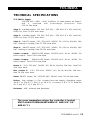
TECHNICAL SPECIFICATIONS
TC5-2N6FA Supply:
115/230 VAC (-18%, +8%), 50/60Hz, L1 same phases as Stage 1
and
2,
overload
and
overvoltage
protection
fuse
F12-1A fast blow.
Stage 1: Variable output, 115 VAC (1/2 HP) / 230 VAC (1.5 HP), Mot.10A,
50/60 Hz, fuse F1-15A slow blow.
Stage 2: Variable output, 115 VAC (1/2 HP) / 230 VAC (1.5 HP), Mot.10A,
50/60 Hz, fuse F2-15A slow blow.
Stage 3: ON-OFF output, 115 / 230 VAC, 30VDC, 50 / 60 Hz, Mot.6A; 10A
Res., heating or cooling, fuse F7-15A slow blow.
Stage 4: ON-OFF output, 115 / 230 VAC, 30VDC, 50 / 60 Hz, Mot.6A; 10A
Res., heating or cooling, fuse F8-15A slow blow.
Curtain 1 output:
OPEN-CLOSE output, 115/230 VAC, 60 Hz, 30VDC, 5A
winch output, fuse F3-5A slow blow.
Curtain 2 output:
OPEN-CLOSE output, 115/230 VAC, 60 Hz, 30VDC, 5A
winch output, fuse F5-5A slow blow.
Heater 1: 115 / 230 VAC, 30VDC, 50 / 60 Hz, Mot.6A; 10A Res., fuse F1015A slow blow.
Mist / Heater 2: 115 / 230 VAC, 30VDC, 50 / 60 Hz, Mot.6A; 10A Res.,
fuse F9-15A slow blow.
Alarm: ON-OFF output, 3A, 115/230 VAC, 30VDC, fuse F11-3A slow blow.
Probes: Low voltage ( < 5V), isolated from the supply. Operating range:
-40.0°F to 120.0°F (-40.0°C to 48.9°C). Accuracy: 1.8°F (1°C) between
41°F and 95°F (5°C and 35°C).
Enclosure: ABS, moisture and dust-tight.
The room temperature where the controller is located
MUST ALWAYS REMAIN BETWEEN 32° AND 104°F (0°
AND 40°C).
TC5-2N6FA rev.01
59
TC5-2N6FA
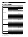
FACTORY SETTINGS
PARAMETER
FACTORY SETTINGS
RANGE OF VALUES
Temperature Set Point
75°F(23.9°C)
0.0°F and 99.0°F
(-17.0°C and 37.2°C)
Minimum Speed
40%
10 % to 100 %
Time On
15 seconds
Time Off
0 seconds
Bandwidth
2°F (1.1°C)
0.5 to 20°F
(0.3 to 11.1°C)
Motor curve
4
Curve 1-10
Humidity Set Point
65%
40 to 100%
Compensation Percentage
60%
0 to 100% of stage 1
minimum speed
Offset
0.5°F (0.3°C)
0.5 to 20°F
(0.3 to 11.1°C)
Bandwidth
2°F(1.1°C)
0.5 to 20°F
(0.3 to 11.1°C)
Min. Speed
40%
10 % to 100 %
De-icing Cycle Time
1 minute
1 to 720 minutes
De-icing Time
15 seconds
15 to 900 seconds
Motor curve
4
Curve 1-10
Differential
2°F (1.1°C)
0.5 to 20°F
(0.3 to 11.1°C)
Dead Band
2°F (1.1°C)
0.5 to 20 °F (0.3 to 11.1 °C)
Time On
15 seconds
10 to 900 seconds
Time Off
90 seconds
0 to 900 seconds
Outside Set Point
70°F (21°C)
-40 to 99.9 °F
(-40 to 37.7 °C)
Offset
8.0°F (4.4°C)
0.5 to 20°F
(0.3 to 11.1°C)
Time On
60 seconds
0 to 900 seconds
in increments of 15 sec.
Time Off
10 minutes
0 to 60 minutes
Offset
14°F (7.8°C)
0.5 to 20°F
(0.3 to 11.1°C)
Differential
2°F (1.1°C)
0.5 to 20°F
(0.3 to 11.1°C)
Mist Shut off humidity level
95%
0 to 99%
(100% = not used)
Heater Differential
2°F (1.1°C)
0.5 to 20°F
(0.3 to 11.1°C)
Heater Offset
2.0°F (1.1°C)
-10 to 20°F
(-5.7 to 11.1°C)
Max. Temperature Diff.
Between Zones
7.5°F(4.2°C)
0.5 to 20°F
(0.3 to 11.1°C)
High Offset
12.0°F(6.7°C)
0.5 to 40°F
(0.3 to 22.2°C)
Low Offset
10.0°F(5.6°C)
0.5 to 40°F
(0.3 to 22.2°C)
Stage 1
Humidity Control
0 to 900 seconds
in increments of 15 sec.
Stage 2
Stages 3 - 4
Curtains
Mist
Heater
Alarms
NOTES: i) Initial parameter settings are not saved once they are modified.
ii) If the power supply is cut off, the last parameter settings recorded until the power is restored.
60 TC5-2N6FA rev.01
TC5-2N6FA
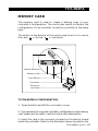
MEMORY CARD
The memory card is used to create a backup copy of your
controller's configuration. The card is also useful to transfer the
configuration of one controller to another controller of the same
type.
The switch at the bottom of the card is used to lock or to unlock
the card (
= locked,
= unlocked).
Internal Switches
Memory Card
Card Switch
Connector
Electronic
top board
TO TRANSFER A CONFIGURATION:
1. Open the latch and lift the controller's cover.
2. If you are about to copy the controller's configuration on the memory
card, make sure the card's switch is at the unlocked position.
3. Insert the card in the connector located on the electric board
inside the controller. Refer to the illustration above to position the
TC5-2N6FA rev.01
61
TC5-2N6FA
memory card correctly.
4. If internal switch #12 is at the OFF position, simply switch it to
the ON position; if internal switch #12 is at the ON posiON
tion: return to the OFF position then switch it back to ON
OFF
again.
12
5. Close the controller's cover.
6. The transfer menu should be displayed on screen. Use the
adjustment buttons to select whether you want to transfer the memory
card's content into the controller ("COPY" "to" "CTRL") or if you
wish to transfer the controller's content into the memory card
("COPY" "to" "CARD") .
7. Once you have chosen the proper type of transfer, press and
hold the Other Functions button for 5 seconds. The controller will
automatically return to the ROOM TEMP menu once the transfer is
completed. If the transfer is incorrect, the letters "COPY" and
"Error" will flash on screen. In this case, turn the adjustment knob
once to exit the error menu then refer to the table below to see
possible error causes.
8. Once the transfer is over, open the controller's cover, and remove the memory card from the connector. Close the controller's
enclosure afterwards.
9. Lock the card switch (
62 TC5-2N6FA rev.01
) if required.
TC5-2N6FA
CAUSE Error:
Transfer
SOLUTION
The memory card is
write protected
If you want to copy the controller's configuration on
the memory card, make sure the switch at the
bottom of the card is at the unlocked position.
The controller is write
protected
If you want to transfer the card's configuration in
the controller, make sure internal switch #1 of the
controller is at the "OFF" position.
The memory card
is blank or its content
is incompatible with
the controller
Make sure a valid configuration is written on the
card before starting a transfer.
The transfer
is incomplete
Make sure the memory card is properly inserted in
the connector then retry the transfer. Do not move
or hold the card while the transfer is ongoing.
The memory card is defective, try with another
card (contact your dealer).
The connector is defective (contact you dealer).
TC5-2N6FA rev.01
63
TC5-2N6FA
GLOSSARY
BANDWIDTH: The temperature interval over which the variablespeed fans of a given stage increase or decrease in speed proportionally to the temperature.
CASCADING HEATERS: Heaters operate in a sequence. As the average room temperature falls, additional heaters are turned on as
needed.
DEFAULT VALUE: A typical parameter setting defined at the factory.
DIFFERENTIAL: The differential is the temperature difference between the moment the constant-speed fans or heating units of a
given stage start running and the moment they return to a stop.
MINIMUM VENTILATION CYCLE: When the room temperature is
below the set point, the Stage 1 fans operate intermittently to provide minimum ventilation to the room.
MINIMUM VENTILATION SPEED RAMP: When Stage 1 operates
variable-speed fans, they will run at minimum speed during the minimum ventilation cycle. The user can define a minimum ventilation
speed ramp to adjust the Stage 1 minimum speed automatically over
a given time period. The minimum speed increases over time as the
animals grow.
OFFSET: An offset is a temperature difference from the set point
that normally defines a cut-off point for a stage operation. For example, a heater offset of 2°F means the heaters will turn off at 2°F
below the set point.
STAGE 1 RAMP: When the temperature rises to the point where
Stage 1 constant-speed fans are needed for cooling, the running time
of the fans is increased gradually from the minimum ventilation settings up to full operation. Likewise, when the temperature falls below the set point, the running time is decreased gradually until the
minimum ventilation settings are reached.
64 TC5-2N6FA rev.01
TC5-2N6FA
SET POINT: The set point is the target room temperature. When the
temperature is above the set point, the controller cools the room by
turning on the cooling fans. When the temperature is below the set
point, the controller heats the room by turning on the heaters.
TEMPERATURE RAMP: The controller can be set to automatically
change the temperature set point over a given period of time in
accordance with the user's requirements. The set point decreases
over time as the animals grow.
ZONED HEATERS: When zoned heaters are used, heaters in each
zone operate according to their own probes rather than the average
temperature for the entire room. In this way, heaters across zones
are independent of one another.
TC5-2N6FA rev.01
65
M 890-00563
rev. 01
REV. 01