1
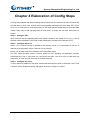
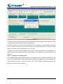
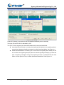
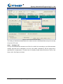
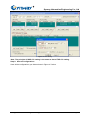
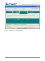
Synway Software Tool
SS7Cfg.exe
Synway Information Engineering Co., Ltd
www.synway.net
Synway Information Engineering Co., Ltd
Contents
Contents ...................................................................................................i
Copyright Declaration............................................................................ii
Chapter 1 Brief Introduction..................................................................1
Chapter 2 Installation Way.....................................................................2
Chapter 3 Usage Description ................................................................3
3.1 Main Interface................................................................................3
3.2 Detailed Instruction ........................................................................3
Chapter 4 Elaboration of Config Steps.................................................7
Appendix A Technical/sales Support..................................................15
SS7Cfg.exe - SS7 Server Configuration Program User Manual
Page i
Synway Information Engineering Co., Ltd
Copyright Declaration
All rights reserved; no part of this document may be reproduced or transmitted in any form or by
any means, electronic or mechanical, without prior written permission from Synway Information
Engineering Co., Ltd (hereinafter referred to as ‘Synway’).
Synway reserves all rights to modify this document without prior notice. Please contact Synway for
the latest version of this document before placing an order.
Synway has made every effort to ensure the accuracy of this document but does not guarantee
the absence of errors. Moreover, Synway assumes no responsibility in obtaining permission and
authorization of any third party patent, copyright or product involved in relation to the use of this
document.
SS7Cfg.exe - SS7 Server Configuration Program User Manual
Page ii
Synway Information Engineering Co., Ltd
Chapter 1 Brief Introduction
SS7Cfg.exe is a software tool provided with the SynCTI driver from Synway. Its main function is to
set the configuration file Ss7server.ini for the SS7 server program Ss7Monitor.exe. An application
system that requires SS7 signaling must run the SS7 server first. Therefore, our company
independently developed out the software tool SS7Cfg.exe to bring users a convenience with its
interface-based design.
SS7Cfg.exe - SS7 Server Configuration Program User Manual
Page 1
Synway Information Engineering Co., Ltd
Chapter 2 Installation Way
Go to our website www.synway.net to download the newly published SynCTI driver program and
install it following the manual SynCti_InstManual.doc. Then you can see the SS7 server
configuration program SS7Cfg.exe and the file SS7Cfg_UserManual.doc (giving instruction for use
of SS7Cfg.exe), as well as the SS7 server application program Ss7Monitor.exe, under the driver
installation directory.
SS7Cfg.exe - SS7 Server Configuration Program User Manual
Page 2
Synway Information Engineering Co., Ltd
Chapter 3 Usage Description
3.1 Main Interface
Run SS7Cfg.exe and the main interface as shown in Figure 3-1 below appears.
3
2
6
10
5
4
7
8
9
11
12
1
Figure 3-1 Main Interface Configuration
3.2 Detailed Instruction
Here we describe all components on the main interface one by one according to the number
illustrated on the figure above.
1--- Five Basic Function Buttons
At the right and bottom edge of the main interface are five basic function buttons as follows.
1)
Default: Recover default settings;
2)
Open: Open a .INI configuration file and display its content at corresponding places;
3)
Save: Save the current configuration;
4)
Save as: Save the current configuration with another filename;
5)
Exit: Exit the program.
SS7Cfg.exe - SS7 Server Configuration Program User Manual
Page 3
Synway Information Engineering Co., Ltd
2--- OPC
Configure the originating point code which is written in the format of a.b.c (a, b, c are all
decimal numbers between 0-255).
3--- Server 1 IP
Set the IP address of the server. In a dual-server system, this IP address should be the actual
IP address.
4--- Server 2 IP
This configuration item is only set for a dual-server system and this IP address should be the
actual IP address.
5--- Signaling Point Code Standard
The default value is 24. The China SS7 common channel network uses the unified format of
24-bit binary code and the specific signaling point code standard varies on the PBX model.
6--- Client Setting
Configure the client that uses SS7 links and voice paths. The number of clients to be
configured can be up to 10.
1) List Box: Display the configured client number and IP address. Double click any line in the
list box and a window ‘Client IP address setting’ appears.
2) Add: Allowed to add a new client when ‘IP address’ is not empty.
3) Modify: Allowed to modify the client information when ‘Number’ is not empty.
4) Delete: Allowed to delete a client whose number is displayed under ‘Number’. However, a
client used by the subsequent configuration can not be deleted until the corresponding
configuration item is deleted.
7--- Signaling Link Setting
An E1 carrying signaling messages is a signaling link. This item is to configure the physical
address of a signaling link, whose structure is: Client Number + Local PCM Number. Note that
the physical address and the signaling link must be put into a one-to-one relationship and at
most 96 signaling links are allowed to be configured.
1) List Box: Display the information about the configured signaling link. Double click any line
in the list box and a window ‘Signaling link setting’ appears.
2) Add: Allowed to add a new signaling link when the list box of ‘Client Setting’ is not empty.
3) Modify: Allowed to modify the signaling link information when ‘Number’ is not empty.
4) Delete: Allowed to delete a signaling link whose number is displayed under ‘Number’.
However, a signaling link used by the subsequent configuration can not be deleted until
the corresponding configuration item is deleted.
8--- Link Group Setting
All signaling links connected with each other between two signaling points compose a link
group. We support up to 2 signaling links involved in a link group and at most 48 link groups to
SS7Cfg.exe - SS7 Server Configuration Program User Manual
Page 4
Synway Information Engineering Co., Ltd
be configured.
1) List Box: Display the information about the configured link group. Double click any line in
the list box and a window ‘Link group setting’ appears.
2) Add: Allowed to add a new link group when ‘Signaling link’ is not empty.
3) Modify: Allowed to modify the link group information when ‘Signaling link’ is not empty.
4) Delete: Allowed to delete a link group whose number is displayed under ‘Number’.
However, a link group used by the subsequent configuration can not be deleted until the
corresponding configuration item is deleted.
9--- DPC Setting
Configure the information about the signaling point (PBX) connected with DPC, including the
signaling point code and the link group.
A signaling point corresponds to a link group. We support the configuration of up to 16 DPC.
1) List Box: Display the information about the configured DPC. Double click any line in the
list box and a window ‘DPC setting’ appears.
2) Add: Allowed to add a new DPC when both ‘Link group’ and ‘SP code’ are not empty.
3) Modify: Allowed to modify the DPC information when ‘Number’ is not empty.
4) Delete: Allowed to delete a link group whose number is displayed under ‘Number’.
10--- TUP CIC Setting
For 2048KB/s digital channels, the lowest 5 bits of CIC represent the data time slot number
and the rest 7 bits indicate the link between a PCM at the local end and a PCM at the client
end.
1) List Box: Display the information about the configured CIC. Double click any line in the list
box and a window ‘CIC setting’ appears.
2) Add: Allowed to add a new CIC when the list box of ‘Client Setting’, ‘Local PCM address’,
‘DPC number’ and ‘CIC_PCM’ in this list box are all not empty.
3) Modify: Allowed to modify the CIC information when ‘Number’ is not empty.
4) Delete: Allowed to delete a CIC whose number is displayed under ‘Number’.
5) TUP message defaults to
0 #IP (-1 means no default client IP): This textbox
corresponds to the configuration item DefaultTupRouterClientIpId, with the default value
of -1 which indicates there is no client available to process the TUP message so that it is
discarded. When DefaultTupRouterClientIpId is set to be X(X≠-1), it means Client X will
process the TUP message. By default 0 is given to this item, and we suggest you modify it
to -1 except in case of special requirements.
11--- ISUP CIC Setting
For 2048KB/s digital channels, the lowest 5 bits of CIC represent the data time slot number
and the rest 7 bits indicate the link between a PCM at the local end and a PCM at the client
end.
SS7Cfg.exe - SS7 Server Configuration Program User Manual
Page 5
Synway Information Engineering Co., Ltd
1) List Box: Display the information about the configured CIC. Double click any line in the list
box and a window ‘CIC setting’ appears.
2) Add: Allowed to add a new CIC when the list box of ‘Client Setting’, ‘Local PCM address’,
‘DPC number’ and ‘CIC_PCM’ in this list box are all not empty.
3) Modify: Allowed to modify the CIC information when ‘Number’ is not empty.
4) Delete: Allowed to delete a CIC whose number is displayed under ‘Number’.
5) TUP message defaults to
0 #IP (-1 means no default client IP): This textbox
corresponds to the configuration item DefaultTupRouterClientIpId, with the default value
of -1 which indicates there is no client available to process the TUP message so that it is
discarded. When DefaultTupRouterClientIpId is set to be X(X≠-1), it means Client X will
process the TUP message. By default 0 is given to this item, and we suggest you modify it
to -1 except in case of special requirements.
12--- Advanced Setting
There are two options under ‘Advanced Setting’ which are not ticked by default.
1) Start in gateway mode: If channels are not required for call connection, it is not necessary
to start the test program. In such case, you only need to start Ss7Monitor.
2) Send test message: If it is ticked, the system will send a signaling link test message every
minute to check whether the link stays normal or abnormal. Otherwise, no signaling link
test messages will be sent.
3) Auto Get DPC/OPC: If it is ticked, the SS7 server will automatically obtain the actual
DPC/OPC from the link, ignoring the set DPC/OPC; otherwise, the SS7 server will use the
set DPC/OPC, not to obtain the actual DPC/OPC from the link. At present it is supported
only in the associated mode.
SS7Cfg.exe - SS7 Server Configuration Program User Manual
Page 6
Synway Information Engineering Co., Ltd
Chapter 4 Elaboration of Config Steps
SS7Cfg.exe is started with default settings which indicate this PC works as not only the server but
also the client. In such case, PCM 0 carries both signaling messages and voice data, DPC: 9.9.9,
OPC: 1.2.3. Users have to reset some items on the main interface depending on the actual PBX
model if they want to add signaling links or PCM paths, or modify the SP code. See below for
details.
Step 1: Configure OPC
OPC is used to set the originating point code which is written in the format of a.b.c (a, b, c are all
decimal numbers between 0-255) and usually allocated by Central Office Terminal (COT).
Step 2: Configure Server IP
Server 1 IP is used to set the IP address of the primary server. It is unnecessary to set the IP
address of the secondary server if there is only one server.
Server 2 IP is used to set the IP address of the secondary server.
The SS7 server provides various services based on SS7 signaling. Its application program
Ss7Monitor.exe, one or more than one, serving as the client, can run at one or more than one
computers, or even run with the server at a same computer.
Step 3: Configure the client
To set or add an IP address of the client, double click the first line or click on the button ‘Add’. Then
a window ‘Client IP address setting’ will appear as shown in Figure 4-1 below.
SS7Cfg.exe - SS7 Server Configuration Program User Manual
Page 7
Synway Information Engineering Co., Ltd
Figure 4-1 Client Setting
You can see from the figure that there are two items under ‘Client Setting’ to be configured: one is
the client number and the other is the client IP address.
The client number is a logical number and needn’t be set manually. It is automatically increased
from 0. If there is only one client, the client number (i.e. the logical number) is 0; if there are two
clients, the number of the second client is 1; and the like.
‘IP address’ is used to set the IP address of the client. A client corresponds to an IP address. If a
client is running with the SS7 server at a same computer, its IP address is just the same as that of
the server.
Step 4: Configure the signaling link
A link delivering signaling messages between two signaling points is called a signaling link. This
item is to set which PCM in which client carries the signaling messages. To add a signaling link,
double click the first line or click on the button ‘Add’. Then a window ‘Signaling link setting’ will
appear as shown in Figure 4-2 below.
SS7Cfg.exe - SS7 Server Configuration Program User Manual
Page 8
Synway Information Engineering Co., Ltd
Figure 4-2 Signaling Link Setting
You can see from the figure that there are two items under ‘Signaling Link Setting’ to be configured:
one is the link number (a logical number) and the other is the actual physical address for
connection.
The link number is not set manually either. It is numbered from 0, automatically plus 1 upon a new
link being added.
Users should determine how many PCM they need configure and which PCM carries the signaling
messages according to their own configurations, and make sure the PCM value filled in is
consistent with the client setting.
Step 5: Configure the link group
A bunch of signaling links that directly connect two signaling points compose a link group. See
Figure 4-3 below.
SS7Cfg.exe - SS7 Server Configuration Program User Manual
Page 9
Synway Information Engineering Co., Ltd
Figure 4-3 Link Group Setting
We support up to 2 signaling links involved in a link group and the option ‘Double link’ should be
ticked in case of two signaling links.
If the default value of OPC is not used, the OPC you manually input has a higher priority than that
in the basic setting.
Step 6: Configure DPC
DPC (Destination Point Code) is written in the format of x.y.z, among which x is the main area
code, y is the subarea code and z is the signaling point code, all allocated by Central Office
Terminal (COT). This item is used to set the DPC that corresponds to each link group.
SS7Cfg.exe - SS7 Server Configuration Program User Manual
Page 10
Synway Information Engineering Co., Ltd
Figure 4-4 DPC Setting
Under ‘DPC Setting’, the number is also increased automatically but not manually.
The input SP code for DPC is allocated by COT.
The SynCTI driver supports both Associated Mode and Quasi-associated Mode.
z
Associated Mode: Directly connecting the signaling links between two signaling points to
transmit the inbetween signaling messages is called Associated Mode. See Figure 4-4.
z
Quasi-associated Mode: Connecting two or more than two signaling links serially via one
or more than one signaling transport points to transmit signaling messages, provided the
path of signaling messages through the signaling network is predetermined and fixed
within a certain period of time, is called Quasi-associated Mode. See Figure 4-5.
SS7Cfg.exe - SS7 Server Configuration Program User Manual
Page 11
Synway Information Engineering Co., Ltd
Figure 4-5 Quasi-associated Mode Setting
The setting of Quasi-associated Mode is the same as that of Associated Mode except for the step
to input an STP code.
Step 7: Configure CIC
First you should determine whether to set TUP CIC or ISUP CIC according to your PBX and board
models. And this item is designed to set the voice paths controlled by the link group that a
specified DPC corresponds to. To add a new CIC setting, double click the first line or click on the
button ‘Add’. See Figure 4-6 below.
SS7Cfg.exe - SS7 Server Configuration Program User Manual
Page 12
Synway Information Engineering Co., Ltd
Figure 4-6 CIC Setting
Note: The principle of ISUP CIC setting is the same as that of TUP CIC setting.
Step 8: Save all configurations
Save all the configurations you did as shown in Figure 4-7 below.
SS7Cfg.exe - SS7 Server Configuration Program User Manual
Page 13
Synway Information Engineering Co., Ltd
Figure 4-7 Configuration Saving
Now the configuration of SS7 Server is completed.
SS7Cfg.exe - SS7 Server Configuration Program User Manual
Page 14
Synway Information Engineering Co., Ltd
Appendix A Technical/sales Support
Thank you for choosing Synway. Please contact us should you have any
inquiry regarding our products. We shall do our best to help you.
Headquarters
Synway Information Engineering Co., Ltd
http://www.synway.net/
9F, Synway D&R Center, No.3756, Nanhuan Road, Binjiang District,
Hangzhou, P.R.China, 310053
Tel: +86-571-88860561
Fax: +86-571-88850923
Technical Support
Tel: +86-571-88864579
Mobile: +86-13735549651
Email: [email protected]
Email: [email protected]
MSN: [email protected]
Sales Department
Tel: +86-571-88860561
Tel: +86-571-88864579
Fax: +86-571-88850923
Email: [email protected]
SS7Cfg.exe - SS7 Server Configuration Program User Manual
Page 15