1
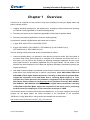
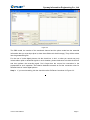
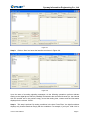
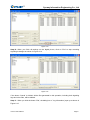
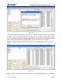
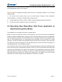
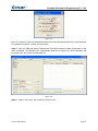
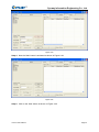
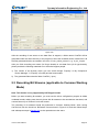
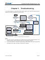
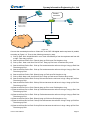
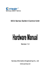
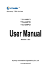
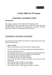
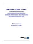
Synway Software Tool
Synway Information Engineering Co., Ltd
www.synway.net
Synway Information Engineering Co., Ltd
Contents
Contents ...................................................................................................i
Copyright Declaration............................................................................ii
Chapter 1 Overview...............................................................................1
Chapter 2 Operation Guide ..................................................................2
2.1
2.2
2.3
Recording Signaling Messages (applicable to Common Working Mode) .....................2
Recording Raw Waves/Raw Data Flows (applicable to Raw Data Acquisition Mode) 11
Recording Bit Streams (applicable to Common Working Mode) .................................18
Chapter 3 Troubleshooting ................................................................20
Appendix A Example of Signaling Content........................................23
Appendix B Example of Standard Raw Wave......................................24
Appendix C Technical/sales Support .................................................26
CasTool User Manual
Page i
Synway Information Engineering Co., Ltd
Copyright Declaration
All rights reserved; no part of this document may be reproduced or transmitted in any form or by
any means, electronic or mechanical, without prior written permission from Synway Information
Engineering Co., Ltd (hereinafter referred to as ‘Synway’).
Synway reserves all rights to modify this document without prior notice. Please contact Synway for
the latest version of this document before placing an order.
Synway has made every effort to ensure the accuracy of this document but does not guarantee
the absence of errors. Moreover, Synway assumes no responsibility in obtaining permission and
authorization of any third party patent, copyright or product involved in relation to the use of this
document.
CasTool User Manual
Page ii
Synway Information Engineering Co., Ltd
Chapter 1
Overview
CasTool.exe is a special tool we provide to help solve problems involving the digital station tap
board, primarily used in:
1. Logging signaling messages for the digital phone, monitoring channel states and recording
on-channel voices (applicable to Common Working Mode).
2. Recording raw waves or raw data flows (applicable to Raw Data Acquisition Mode).
3. Recording bit streams (applicable to Common Working Mode)
At present the models of digital station tap boards are as follows:
1. A-type: SHR-16DA-CT/PCI, SHR-24DA-CT/PCI
2. B-type: DST-24B/PCI, DST-24B/PCI+, DST-24B/PCI(2.0), DST-24B/PCI+(2.0),
DST-24B/PCIe(2.0), DST-24B/PCIe+(2.0)
The two working modes mentioned above are described as follows:
1. Common Working Mode: It is selected in case that the check box before ’Rec Raw Mode’ is
not ticked when using ShCtiConfig.exe to configure such information as PBX model, etc. In
this mode, you can perform the recording of signaling messages (applicable to both A-type
and B-type boards) or bit streams (applicable only to B-type boards). The bit stream is the
effective raw data composed of voice data and signaling messages, generated by parsing the
original waveforms.
2. Raw Data Acquisition Mode: It is selected in case that the check box before ’Rec Raw Mode’ is
ticked when using ShCtiConfig.exe to perform configuration. Note: SHR-16DA-CT/PCI and
SHR-24DA-CT/PCI digital station tap boards, if working in Raw Data Acquisition Mode,
support the acquisition of raw data flows, that is, collecting digital signals 0 or 1 at a
specified rate. Some operations on parameter configuration may be required to enable
this feature. Please contact us (see Appendix B) for help when necessary. DST-24B/PCI,
DST-24B/PCI+, DST-24B/PCIe and DST-24B/PCIe+ digital station tap boards, if working
in Raw Data Acquisition Mode, support the acquisition of raw waves, that is, performing
the A/D conversion sampling to on-line raw waves at the rate of 10M/S.
This software cannot run without ShConfig.ini and ShIndex.ini, so you must configure ShConfig.ini
properly for the digital station tap board according to the description in the document
‘DSTBoard_Config_Manual.pdf’, which can be downloaded from the link below:
http://www.synway.net/DownLoad/DST_help_document.rar
CasTool User Manual
Page 1
Synway Information Engineering Co., Ltd
Chapter 2
Operation Guide
2.1 Recording Signaling Messages (applicable to Common
Working Mode)
Step 1: Start CasTool.exe and the main interface shows as Figure 2-1.
Figure 2-1
As seen in Figure 2-1, there are two columns ‘TestInfo’ and ‘ChInfo’ on the top of the left list
window. The ‘TestInfo’ will cover such information as Ch, ChState, DTMF BUFFER, DKEY, LCD
INFO, CallerId and CalledId, while the ‘ChInfo’ will show the monitored situation in real time. The
right list window will display the D-channel event code and other parameters in turn.
The item ‘Event Filter’ at the bottom is used to set conditions for which events you exactly want to
display. For example, if you only want events with the event code of 1008 and 104a to be
displayed, fill in ‘1008 104a’; if you want all events but those with the event code of 1008 and 104a
to be displayed, fill in ‘1008 104a’ and tick the check box ‘Exclude’. Note that up to 10 event filter
conditions can be set at a time and the filled-in event codes should be separated by blank space.
Step 2: Fill in some parameters under ‘Channel Info’ as shown in Figure 2-2.
CasTool User Manual
Page 2
Synway Information Engineering Co., Ltd
Figure 2-2
The PBX model, the number of the monitored channel and the phone model are the essential
information that you must input (that is, these three fields can’t be left empty). They will be written
into the generated log file.
For the use of 4-wire digital phones, tick the check box ‘4 wire’; or what you record may only
include either uplink or downlink signals. In such situation, please make sure to tick this check box
and then perform the recording again. Don’t forget that the correct line connection is the
prerequisite for such operation. See relative hardware manuals to find the connection rules for
different kinds of 4-wire digital phones.
Step 3: If you need recording, tick the check box after ‘EnRecord’ as shown in Figure 2-3.
CasTool User Manual
Page 3
Synway Information Engineering Co., Ltd
Figure 2-3
As long as ‘EnRecord’ is ticked, the program will automatically record A-Law formatted WAV files
under the directory of the log file.
Step 4: When you finish setting the parameters under ‘Channel Info’, click on ‘Set’ as shown in
Figure 2-4.
Figure 2-4
Step 5: Then the dialog box of ‘Success to set channel’ will pop up as shown in Figure 2-5.
CasTool User Manual
Page 4
Synway Information Engineering Co., Ltd
Figure 2-5
After the channel is set successfully, a folder named ‘CasFile’ will be generated under the same
directory of the program to store the recorded signaling logs and voice files. And the signaling logs
and voice files are named in the form of ‘hour_minute_second’, e.g. 15_24_35.log, 15_24_35.wav.
As to the format of the signaling content, please refer to Appendix A.
Step 6: Click on ‘OK’ back to the main window. Now the button ‘Start’ is activated as shown in
Figure 2-6.
Figure 2-6
Step 7: At this time, you can click on the button of ‘Start’ to record signaling messages as shown
in Figure 2-7.
CasTool User Manual
Page 5
Synway Information Engineering Co., Ltd
Figure 2-7
Step 8: Click on ‘Start’ and enter the interface as shown in Figure 2-8.
Figure 2-8
Upon the start of recording signaling messages, do the following operations: perform relevant
testing on the digital phone which is parallelly connected to the monitored channel (i.e. the channel
with the number set in the previous step), record the testing time, content and the information
displayed in the column ‘ChInfo’.
Step 9: This step is optional. By setting conditions in the item ‘Event Filter’, the right list window
displays only those events that comply with the conditions. For example, if you input ‘1008 1001’ to
CasTool User Manual
Page 6
Synway Information Engineering Co., Ltd
the item ‘Event Filter’, then the right list window (i.e. the D-channel events list) will output those
events with the event code of 1008 or 1001. See Figure 2-9.
Figure 2-9
If you tick the check box before ‘Exclude’, the right list window only displays the events incompliant
with the filled-in conditions. See Figure 2-10.
Figure 2-10
When you click the button ‘ClearEvents’, all events that are already shown in the right list window
will be cleared out. However, it won’t disturb the display of subsequent events. See Figure 2-11.
CasTool User Manual
Page 7
Synway Information Engineering Co., Ltd
Figure 2-11
When you click the button ‘Event Pause’, the event output is stopped and the button name
changes to be ‘Event Continue’. See Figure 2-12.
Figure 2-12
If you want the list window to go on displaying the events, click the button ‘Event Continue’. See
Figure 2-13.
CasTool User Manual
Page 8
Synway Information Engineering Co., Ltd
Figure 2-13
Step 10: When you finish all testings on the digital phone, click on ‘End’ to stop recording
signaling messages as shown in Figure 2-14.
Figure 2-14
If the button ‘Cancel’ is clicked, all the files generated in this operation, including both signaling
logs and voice files, will be deleted.
Step 11: When you click the button ‘End’, the dialog box of ‘Log Information’ pops up as shown in
Figure 2-15.
CasTool User Manual
Page 9
Synway Information Engineering Co., Ltd
Figure 2-15
Write down all abnormal phenomena that you ever met into ‘Describe Problem’ and ‘Describe
Operation’, such as ‘channel state transition is inaccurate’, ‘fail to detect the calling party number’,
etc. In the ‘Describe Operation’, please describe the relevant testings on the monitored digital
phone that you did in Step 8 as clear as possible. Then click on ‘OK’ upon completion.
Step 12: Go back to the main interface and click on ‘Exit’ to exit the program. See Figure 2-16
below.
Figure 2-16
Note: A log file will be generated once the buttons ‘Start’ and ‘End’ are pressed. So during the
CasTool User Manual
Page 10
Synway Information Engineering Co., Ltd
testing process, you need repeat this operation for each call. And each operation will be recorded
to an independent log file for our analysis.
After you finish the signaling recording, please provide the following materials to our technical
support people.
1) The version of the Synway driver (you can check through ‘Property’ of My ComputerÆ
‘Device Manager’ Æ ‘Property’ of board) and the board model;
2)
The generated files under the folder ‘CasFile’ (including signaling logs and voice files);
3)
The file ‘ShConfig.ini’ loaded for the run of CasTool.exe.
2.2 Recording Raw Waves/Raw Data Flows (applicable to
Raw Data Acquisition Mode)
The preparation for recording raw waves or raw data flows:
Before you start recording raw waves or raw data flows, you must use the driver configuration
program to delete unrelated boards, making sure that only those with raw waves or raw data flows
to be recorded are remained, and connect lines only to a specified channel on those boards. Note
that for 4-wire digital phones, you need perform two recordings of the raw waves for a same
operation. Connect the uplink to the specified channel and do the first recording. Then disconnect
the uplink and connect the downlink to the specified channel, and do the second recording. For
2-wire digital phones, one recording is enough.
The recording of raw waves or raw data flows should be performed in Raw Data Acquisition Mode
which can be set by the configuration program in driver. For DST A-type boards, after ticking the
check box ‘Rec Raw Mode’, you need to use the button ‘set’ to evaluate the module type with the
PBX model that you choose. See Figure 2-17 below. For DST B-type boards, tick the check box
‘Rec Raw Mode’ and choose the closest PBX model (Note: we suggest you choose Alcatel
4200/4400 if your PBX model is not yet supported). See Figure 2-18 below.
CasTool User Manual
Page 11
Synway Information Engineering Co., Ltd
Figure 2-17 For A-type Boards
Figure 2-18 For B-type Boards
Step 1: Start CasTool.exe and tick the check box after ‘Raw Wave’ (for B-type boards) or ‘Raw
Bits’ (for A-type boards). Note: What displays on the interface for B-type boards is ‘Raw
CasTool User Manual
Page 12
Synway Information Engineering Co., Ltd
Wave’ as shown in Figure 2-19, while that for A-type boards is ‘Raw Bits’ as shown in Figure
2-20.
Figure 2-19 For B-type Boards
Note: Before running CasTool to record raw waves on a DST B-type board, you may need to add
configuration items about analog switch to the file ShConfig.ini. For detailed information, contact
our technicians.
Figure 2-20 For A-type Boards
While recording raw data flows on a DST A-type board, you may need to set some parameters.
Click on ‘Advance Set’ to go into the dialog ‘Advance Setting’ as shown in Figure 2-21.
CasTool User Manual
Page 13
Synway Information Engineering Co., Ltd
Figure 2-21
Note: The values of these two parameters shown above should be determined by actual situations.
For detailed information, contact our technicians.
Step 2: Fill in the PBX and phone models and the specified channel number respectively for the
items ‘PbxModel’, ‘PhoneModel’ and ‘ChannelNum’ as shown in Figure 2-22. Such information will
be saved to the end of the recorded data file.
Figure 2-22
Step 3: Click on the button ‘Set’ as shown in Figure 2-23.
CasTool User Manual
Page 14
Synway Information Engineering Co., Ltd
Figure 2-23
Step 4: Now the ‘Start’ button is activated as shown in Figure 2-24.
Figure 2-24
Step 5: Click on the ‘Start’ button as shown in Figure 2-25.
CasTool User Manual
Page 15
Synway Information Engineering Co., Ltd
Figure 2-25
Step 6: Then the right area shows the size of the currently recorded data file as shown in Figure
2-26. Normally, the sampling rate for B-type boards is about 10M/S while that for A-type boards
depends on parameter settings.
Figure 2-26
Step 7: Click on the ‘End’ button to stop acquiring raw data as shown in Figure 2-27.
CasTool User Manual
Page 16
Synway Information Engineering Co., Ltd
Figure 2-27
Step 8: Then the dialog box of ‘Log Information’ pops up as shown in Figure 2-28. Fill in the two
items ‘Describe Problem’ and ‘Describe Operation’ and click on ‘OK’ upon completion. All the
information you write will be saved to the end of the data file for our developer’s analysis.
Figure 2-28
Step 9: Click on the ‘Exit’ button to exit CasTool.exe as shown in Figure 2-29.
CasTool User Manual
Page 17
Synway Information Engineering Co., Ltd
Figure 2-29
After the recording of raw waves or raw data flows is stopped, a folder named ‘CasFile’ will be
generated under the same directory of the program to store the recorded waves or data flows. All
the files generated therein are named in the form of ‘hour_minute_second’, e.g. 16_23_18.pcm.
After you finish recording raw waves (for B-type boards) or raw data flows (for A-type boards),
please provide the following materials to our technical support people.
1) The version of the Synway driver (you can check through ‘Property’ of My ComputerÆ
‘Device Manager’ Æ ‘Property’ of board) and the board model;
2) The generated files under the folder ‘CasFile’ (*.pcm).
2.3 Recording Bit Streams (applicable to Common Working
Mode)
Note: This feature is only supported by DST B-type boards.
Before you start recording bit streams, you must use the driver configuration program to delete
unrelated boards, making sure that only those with bit streams to be recorded are remained, and
connect lines only to Channel 0 on those boards.
The recording of bit streams should be performed in Common Working Mode. After running
CasTool.exe, tick the check box ‘Bit Stream’ first as shown in Figure 2-30, and then follow Step 2
and subsequent steps in Section 2.2 as the operations are the same.
CasTool User Manual
Page 18
Synway Information Engineering Co., Ltd
Figure 2-30
A file will be generated after finish recording bit stream. This file is stored under the folder ‘CasFile’.
The folder ‘CasFile’ has a same directory of the program. The data file is named in the form of
‘hour-minute-second’, e.g. 16_23_18.bit.
After you finish the signaling recording of the bit stream, please provide the following materials to
our technical support people.
After the recording of bit streams is stopped, a folder named ‘CasFile’ will be generated under the
same directory of the program to store the recorded bit streams. All the files generated therein are
named in the form of ‘hour_minute_second’, e.g. 16_23_18.bit.
After you finish recording bit streams, please provide the following materials to our technical
support people.
3) The version of the Synway driver (you can check through ‘Property’ of My ComputerÆ
‘Device Manager’ Æ ‘Property’ of board) and the board model;
4) The generated files under the folder ‘CasFile’ (*.bit).
CasTool User Manual
Page 19
Synway Information Engineering Co., Ltd
Chapter 3
Troubleshooting
If you have questions in using DST boards, please replace them with DST B-type boards to
diagnose the system following the flow shown below.
Entry
Question
NO (Unsupported)
Either PBX or
phone models
are supported?
Follow the driver default
options to record original
waveforms for silence and
dial tones and control the
recording period within
10s (Note: Silence and
dial tones are allowed to
record into a same file).
NO
YES
Voices
sound
normal?
NO
There appear noises
occasionally? Voices sound
normal most of the time?
Compress recorded
files and send them
to our technical
support department
for further analysis.
YES
NO
The deviation of
clearness in a call is
relatively large.
YES
Record bitstreams
that represent the
signaling aberration
in operation.
NO
Signaling goes
normal? (Judged
by Software and
Hardware
developers)
YES
Modify the driver.
Compress recorded
files and send them
to our technical
support department
for further analysis.
D-channel events go
normal? (Determined by
repeated tryouts the client
performs)
Hardware engineers modify
the RBF file and contact
clients to give it a trial.
YES
NO
YES
Set a reasonable
value for the analog
switch and record 15
original waveforms.
(Note: See Figure
3-2 for details)
Configure the analog switch
option by your PBX model
and record original
Set the A/µ-Law
waveforms for silence and
conversion switch.
dial tones. Control the
recording period within 10s
(Note: Silence and dial
Voices
NO tones are allowed to record
sound
into a same file).
normal?
Compress recorded files and send
them to our technical support
department for further analysis.
Hardware engineers modify the RBF
file and contact clients to give it a trial.
End
Figure 3-1 Troubleshooting Flow for DST Boards
Notes:
1. You need to add the configuration item AnalogCtrl before recording original waveforms. See
detailed information about AnalogCtrl, read SynCTI Programmer’s Manual.
2. If you meet problems in using DST A-type boards, please replace them with B-type boards
and diagnose the system according to the above flow diagram.
CasTool User Manual
Page 20
Synway Information Engineering Co., Ltd
Parallel
connector
Ext1
Ext0
DST-24B Board
PSTN
Dir0
Figure 3-2
Connect the recorded phone line to Channel 0 of the DST-24B digital station tap board in parallel,
according to Figure 3-2. Then do the following test step by step.
1) Pick up Ext0. Dial ‘123456789*0#’ in turn. Push functional keys from the top down and from left
to right. Then hang up Ext0.
2) Start a call from Ext0 to Ext1. Directly hang up Ext0 once Ext1 begins to ring.
3) Pick up Ext1. Start a call from Ext0 to Ext1. Hang up Ext0 once it receives busy tones.
4) Start a call from Ext0 to Ext1. Pick up Ext1 and answer the call once it rings. Hang up Ext0 first.
Then hang up Ext1.
5) Start a call from Ext0 to Ext1. Pick up Ext1 and answer the call once it rings. Hang up Ext1 first.
Then hang up Ext0.
6) Start a call from Ext0 to Dir0. Directly hang up Ext0 once Dir0 begins to ring.
7) Pick up Dir0. Start a call from Ext0 to Dir0. Hang up Ext0 once it receives busy tones.
8) Start a call from Ext0 to Dir0. Pick up Dir0 and answer the call once it rings. Hang up Ext0 first.
Then hang up Dir0.
9) Start a call from Ext0 to Dir0. Pick up Dir0 and answer the call once it rings. Hang up Dir0 first.
Then hang up Ext0.
10) Start a call from Ext1 to Ext0. Directly hang up Ext1 once Ext0 begins to ring.
11) Start a call from Ext1 to Ext0. Pick up Ext0 and answer the call once it rings. Hang up Ext1 first.
Then hang up Ext0.
12) Start a call from Ext1 to Ext0. Pick up Ext0 and answer the call once it rings. Hang up Ext0 first.
Then hang up Ext1.
13) Start a call from Dir0 to Ext0. Directly hang up Dir0 once Ext0 begins to ring.
14) Start a call from Dir0 to Ext0. Pick up Ext0 and answer the call once it rings. Hang up Dir0 first.
Then hang up Ext0.
15) Start a call from Dir0 to Ext0. Pick up Ext0 and answer the call once it rings. Hang up Ext0 first.
Then hang up Dir0.
CasTool User Manual
Page 21
Synway Information Engineering Co., Ltd
Notes:
To improve the analysis accuracy of the LCD information events and the indicator events, we
strongly suggest that you record a clear video of Ext0 or take some photos reflecting the change in
the indicators and LCD of Ext0 while performing Step2, Step5, Step6, Step9, Step11 and Step14
above. Send these videos or photos to our technicians together with the raw waves and the bit
stream files.
CasTool User Manual
Page 22
Synway Information Engineering Co., Ltd
Appendix A Example of Signaling Content
The format of the output log files:
0234 10:4:48
DST ch[
3a 34 33 20 70 6d 20
0] CmdType[D] Len[ 19] Data--> 6a 13 80 4d 61 72 20 31 32 20 31 32
0235
10:4:51
DST ch[
0] CmdType[D] Len[
1] Data--> 43
0236
10:4:51
DST ch[
0] CmdType[D] Len[
1] Data--> 1f
0237
10:4:51
DST ch[
0] CmdType[U] Len[
1] Data--> ce
0238
10:4:55
DST ch[
0] CmdType[D] Len[
1] Data--> 5c
PBX Model: Norstar
Phone Model: M7310
Describe Problem: ‘Caller ID not received…’
Describe Operation: ‘Call out…’
CasTool User Manual
Page 23
Synway Information Engineering Co., Ltd
Appendix B Example of Standard Raw Wave
Refer to Section 2.2 for the recording of raw waves. Because such problems as wrong
connections and disturbs in the physical environment may probably result in unstandard waves
which are not applicable for analysis, we provide a basic analysis method of raw waves hereinafter
for your reference.
1.
Download and install the voice analysis software CoolEdit.
2.
Follow the figures shown below to open the *.pcm file of the recoded raw wave with CoolEdit.
3.
Roll the mouse to enlarge your recorded raw wave figure and observe its details. A standard
raw wave is as follows in the figure. Whether the channel is in a talking state or not, a
standard raw wave recorded must consist of periodic frames. Each frame period is 125ms or
250ms (250ms in the figure below) and contains an uplink signal and a downlink signal. If the
wave you record looks quite different from the standard raw wave, please examine your
connections and the physical environment.
CasTool User Manual
Page 24
Synway Information Engineering Co., Ltd
CasTool User Manual
Page 25
Synway Information Engineering Co., Ltd
Appendix C Technical/sales Support
Thank you for choosing Synway. Please contact us should you have any
inquiry regarding our products. We shall do our best to help you.
Headquarters
Synway Information Engineering Co., Ltd
http://www.synway.net/
9F, Synway D&R Center, No.3756, Nanhuan Road, Binjiang District,
Hangzhou, P.R.China, 310053
Tel: +86-571-88860561
Fax: +86-571-88850923
Technical Support
Tel: +86-571-88864579
Mobile: +86-18905817070
Email: [email protected]
Email: [email protected]
MSN: [email protected]
Sales Department
Tel: +86-571-88860561
Tel: +86-571-88864579
Fax: +86-571-88850923
Email: [email protected]
CasTool User Manual
Page 26