1
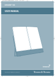
USER MANUAL
SAILOR SYSTEM 5000 MF/HF
150/250/500W
Introduction
Congratulations on your new SAILOR CU5100 MF/HF maritime radio telephone with built-in
DSC (Digital Selective Calling) system, fulfilling the highest international standards for
marine MF/HF communication and safety procedures. The transceiver is born with a
2187,5kHz DSC watch receiver forming an ideal system for MF GMDSS installations. The
transceiver can easily be upgraded for 6 channel scanning DSC watch receiver and Telex
operation to comply with MF/HF requirements in sea area A3. If connected to a GPS or other
maritime navigation system it can automatically include the true UTC time and your position
in its DSC distress messages.
This SAILOR marine equipment is a part of the modular system 5000 which also includes a
HF single sideband radiotelephone. SAILOR marine equipment is specially designed for the
extremely rugged conditions on bord a ship, based on more than 50 years’ experience with
all kinds of boats, from small pleasure crafts, over fishing boats working under all climatic
conditions, to the biggest ships.
SAILOR ® is one of the worlds leading manufacturers of maritime radiocommunication
equipment - a position which has been maintained by means of constant and extensive
product development. We have a worldwide network of dealers with general agencies in
more than 80 countries. All our dealers are specially trained to service all your SAILOR ®
products.
About this manual
This manual is for the daily user of the system. Additionally, it includes a section on the
installation procedures, and - on page iii - standard distress procedures. We highly recommend you to read the manual before you start using the equipment.
Notice: There may be some minor differences in the graphic layout of the manual compared
to the physical device.
Disclaimer
Any responsibility or liability for loss or damage in connection with the use of this product and
the accompanying documentation is disclaimed by Thrane & Thrane. The information in this
manual is provided for information purposes only, is subject to change without notice, may
contain errors or inaccuracies, and represents no commitment whatsoever by Thrane &
Thrane. This agreement is governed by the laws of Denmark.
Manuals issued by Thrane & Thrane are periodically revised and updated. Anyone relying on
this information should satisfy himself/herself as to the most current version. Providers with
access to Thrane & Thrane’s Extranet may obtain current copies of manuals at: http://
extranet.thrane.com.
Thrane & Thrane is not responsible for the content or accuracy of any translations or
reproductions, in whole or in part, of this manual from any other source.
0735
i
Training Information (valid for TU5160)
The System 5000 MF/HF is designed for “occupational use only” and is also classified as
such.
It must only be used in the course of employment by individuals aware of both the hazards
as well as the way to minimize those hazards.
The radio is thus NOT intended for use in an uncontrolled environment by general public.
The System 5000 MF/HF has been tested and complies with the FCC RF exposure limits for
“Occupational Use Only”. The radio also complies with the following guidelines and
standards regarding RF energy and electromagnetic energy levels including the
recommended levels for human exposure:
• FCC OET Bulletin 65 Supplement C, evaluating compliance with FCC guidelines for
human exposure to radio frequency electromagnetic fields
• American National Standards Institute (C95.1) IEEE standard for safety levels with
respect to human exposure to radio frequency electromagnetic fields, 3 kHz to 300
GHz
• American National Standards Institute (C95.3) IEEE recommended practice for the
measurement of potentially hazardous electromagnetic fields – RF and microwaves
Below the RF exposure hazards and instructions in safe operation of the radio within the
FCC RF exposure limits established for it are described.
Warning:
Your radio set generates electromagnetic RF (radio frequency) energywhen it is transmitting.
To ensure that you and those around you are not exposed to excessive amounts of that
energy (beyond FCC allowable limits for occupational use) and thus to avoid health hazards
from excessive exposure to RF energy, FCC OET bulletin 65 establishes an Maximum
Permissible Exposure (MPE) radius of 6" (1.8m) for the maximum power of your radio (150W
selected) with a whip antenna having a maximum gain of 3.0dBi.
This means all persons must be at least 6" (1.8m) away from the antenna when the radio is
transmitting.
Installation:
1. A whip antenna with a maximum power gain of 3 dBi must be mounted at least 12.6"
(3.9m) above the highest deck where people may be staying during radio transmissions.
The distance is to be measured vertically from the lowest point of the antenna. This
provides the minimum separation distance which is in compliance with RF exposure
requirements and is based on the MPE radius of 6" (1.8m) plus the 6.6" (2.0m) height of
an adult.
2
On vessels that cannot fulfil requirements in item 1, the antenna must be mounted so
that its lowest point is at least 6" (1.8m) vertically above the heads of people on deck and
all persons must be outside the 6" (1.8m) MPE radius during radio transmission.
•
•
•
Always mount the antenna at least 6" (1.8m) from possible human access
Never touch the antenna when transmitting
Use only authorized T&T accessories
3. If antenna has to be placed in public areas or near people with no awareness of the radio
transmission, the antenna must be placed at a distance not less than 12" (3.6m) from
possible human access.
Failure to observe any of these warnings may cause you or other people to exceed FCC RF
exposure limits or create other dangerous conditions.
ii
0735
Abbreviations used in this manual
ADDR
AGC
AM
ARQ
CLRF
CU
DIRTLX
DSC
ETSI
FEC
GA
GMDSS
GPS
HF
H3E
IMO
IRS
ISS
ITU
J3E
MF
MMSI
MOM
MSG
NBDP
PTT
RF-G
Rx
SSB
TEL
Tx
UTC
VHF
WRU
0735
Address
Automatic Gain Control
Amplitude Modulation
Automatic Repetition reQuest
Clarify
Control Unit
Direct Telex
Digital Selective Calling
European Telecommunications Standards Institute
Forward Error Correction
Go Ahead
Global Maritime Distress and Safety System
Global Positioning System
High Frequency
Single sideband - full carrier
International Maritime Organisation
Information Receiving Station
Information Sending Station
International Telecommunication Union
Single sideband - no carrier
Medium Frequency
Maritime Mobile Ship Identification
Just a moment please
Message
Narrow Band Direct Printing
Push-To-Talk
Receiver Frequency Gain
Receive
Single Side Band
Telephony
Transmit
Co-ordinated Universal Time
Very High Frequency
Who Are You
iii
Safety instruction
DANGER
Never touch the Antenna Tuning Unit or feeder wire when the
radiotelephone is transmitting.
High voltage which will cause death or serious injury is present at the
locations shown in the illustration below when the radiotelephone is
transmitting.
Feeder wire
(High Voltage)
Antenna
Tuning
Unit
99-126550
WARNING
ELECTRICAL SHOCK HAZARD
Do not open the equipment.
Only qualified personnel should work inside the equipment.
iv
0735
Quick DSC distress call
(only for emergency use)
1. If necessary, switch on by pressing the ON/OFF button
2. Lift up the lid covering the orange
key and press for 3 seconds.
3. The distress will be accompanied by a sound.
Distress message is sent at the continuous tone.
4. Wait for distress acknowledgement and start mayday procedure. Unless stopped
manually, by pressing the CANCEL softkey or switching the unit off, the distress call is
automatically repeated every 3½-4½ minutes until distress acknowledgement is received.
If an alarm panel is connected the MF/HF DISTRESS button on this unit will have the same
functionality as the distress button described above. All further handling should continue in
front of your main MF/HF DSC.
Mayday procedure
When DSC distress acknowledgement is received after you have pressed DISTRESS, or if
you otherwise need to commence distress traffic via radiotelephony on the distress traffic
frequency, follow this procedure:
•
•
•
•
•
•
•
•
•
the distress signal MAYDAY, spoken three times;
the words THIS IS;
the NAME of the vessel in distress, spoken three times;
the CALL SIGN or other identification;
the MMSI if needed;
the POSITION given as the LATITUDE and LONGITUDE or with respect to known
geographical location,
the NATURE of the distress;
the kind of ASSISTANCE required; and
any other useful INFORMATION
Upon reception of a DSC distress alert from another ship in distress, you should acknowledge the receipt by radiotelephony on the distress traffic frequency, by doing the following:
•
•
•
•
•
the distress signal MAYDAY;
the words THIS IS;
the NAME of the vessel in distress, spoken three times;
the NAME or other identification of own ship, spoken three times;
“RECEIVED MAYDAY”.
Transmission of DSC distress alert on MF/HF (2, 4, 6, 8, 12, 16 MHz)
2187.5 kHz,
4207.5 kHz,
6312.0 kHz,
8414.5 kHz,
12577.0 kHz,
0735
16804.5 kHz
v
The MF/HF at a glance
(CU5100)
1
6
7
8
2
9
1. Display.
2. Dimming button.
3. Mode button used to.
toggle between modes.
4. Menu button.
Access to the menu system.
5. Keyboard.
6. Loudspeaker.
7. DISTRESS button.
Protected by shield. To use,
lift the shield and press for 3 seconds.
vi
3
4
5
10
8. Soft keys.
The function of each key is described in
its respective field in the display above
each key.
9. Adjust/Tune.
Multi purpose rotary knob.
Controls backlight, frequency and RX
tune range.
10. ON/OFF / VOLUME control
0735
Contents
Introduction ............................................................................................................................. iii
About this manual ................................................................................................................ iii
Training Information ............................................................................................................ iv
Abbreviations used in this manual ...................................................................................... v
Safety instruction ................................................................................................................ vi
Quick DSC distress call ......................................................................................................... vii
Mayday procedure .................................................................................................................. vii
The MF/HF at a glance (CU5100) ......................................................................................... viii
0735
1
MF/HF Fundamental info ................................................................................................... 3
2
Basic functions .................................................................................................................. 4
2.1 Powering MF/HF ......................................................................................................... 4
2.2 Speaker volume .......................................................................................................... 4
2.3 Switches loudspeaker On/Off ..................................................................................... 4
2.4 Change output power ................................................................................................. 4
2.5 Squelch On/Off ........................................................................................................... 4
2.6 Dimming ...................................................................................................................... 5
2.7 Change mode .............................................................................................................. 5
2.8 How to operate the menu ........................................................................................... 5
2.9 How to make a call to a coast station ........................................................................ 6
2.10 Telephony display functions ....................................................................................... 6
3
Voice call operation ........................................................................................................... 7
3.1 Operating MF/HF radio communication ..................................................................... 7
3.2 Listening for calls from a coast station ....................................................................... 7
3.3 Enter Rx/Tx frequency ................................................................................................ 8
3.4 Channel entry .............................................................................................................. 9
3.5 Select a channel from the station table .................................................................... 11
3.6 Re-tune the Antenna tuner ....................................................................................... 12
4
DSC operation .................................................................................................................. 13
4.1 DSC main .................................................................................................................. 13
4.2 DSC setup ................................................................................................................. 14
4.3 Receiving a Distress Call ......................................................................................... 16
4.4 Receiving an Individual call ...................................................................................... 17
4.5 Sending a test call .................................................................................................... 19
4.6 Calling a coast station .............................................................................................. 21
4.7 Calling a ship ............................................................................................................ 23
4.8 Sending an area call ................................................................................................. 25
4.9 Repeat a call ............................................................................................................. 27
4.10 Composed DSC calls ............................................................................................... 28
4.11 DSC call menu .......................................................................................................... 30
4.12 Geographic Area Computation ................................................................................. 30
5
User setup ......................................................................................................................... 31
1
6
Telex operation ................................................................................................................. 32
6.1 Telex setup ................................................................................................................ 32
6.2 Simple telex operation .............................................................................................. 33
6.3 Telex via data terminal ............................................................................................. 39
7
Data call ............................................................................................................................ 39
8
Scanning ........................................................................................................................... 40
9
Watch keeping receiver ................................................................................................... 41
9.1 Watch receiver setup ................................................................................................ 41
10 Menu tree .......................................................................................................................... 42
11 Installation ........................................................................................................................ 44
11.1 Compass safe distance ............................................................................................ 44
2
0735
MF/HF Fundamental info
Propagation of MF and HF Radio Waves.
MF/HF radiocommunications provide a medium and long range service. The 1.6-4 MHz
marine band is intended primarily for coastal operation beyond normal VHF communication
range. A reliable range of more than 150 nautical miles can be expected in most areas in the
daytime, more in the nighttime. Propagation of the radio waves in this band is mainly by
ground waves i.e. the waves from the transmitter aerial follow the earth’s curvature to the
receiver aerial. The high frequency range 4 - 30 MHz can provide communication for
hundreds or even thousands of nautical miles. The long range is achieved by sky waves
reflected from the ionosphere. Propagation of the radio waves depends on a number of
factors such as frequency, time of day, time of year, and solar activity. The channels
allocated to the maritime mobile service in the HF range are divided into a number of bands:
4, 6, 8, 12, 16, 18, 22, 25 MHz to allow a suitable frequency band to be selected for communication dependent on distance and time of day.
Radiotelephony
The mode of emission used for telephony transmissions in the marine bands is SSB (singlesideband, J3E). On the international distress frequency 2182 kHz compatible AM (amplitude
modulation, H3E) may be used in addition for communication with non-GMDSS ships. AM
mode is used also when receiving broadcasting. The frequencies for radiotelephone distress
and safety traffic in the HF bands are 4125 kHz, 6215 kHz, 8291 kHz, 12290 kHz, and 16420
kHz. Working frequencies for public correspondence with coast stations are arranged in pairs
for duplex/semi-duplex operation. For the HF bands these channels are allocated numbers
by ITU on an international basis. In addition a number of simplex frequencies are available in
each band for ship-to-ship communication.
Radiotelex
Marine telex is also referred to as (NBDP) ‘Narrow Band Direct Printing’. Due to the narrow
bandwidth of the transmissions, a longer range may be expected compared to radiotelephony. The frequencies for radiotelex distress and safety traffic are 2174.5 kHz, 4177.5
kHz, 6268 kHz, 8376.5 kHz, 12520 kHz, and 16695 kHz. Working frequencies for public
correspondence with coast stations are arranged in pairs. For the HF bands these channels
are allocated numbers by ITU on an international basis. In addition a number of simplex
frequencies are available in each band for ship-to-ship communication.
DSC
DSC (Digital Selective Calling) is an automatic calling system which allows a specific station
to be contacted and made aware that a station wishes to communicate with it. In addition to
calls to specific stations the system can also be used to call groups of ships and this is of
significance for its use for DSC distress alerting. DSC is an alerting signal only and the
communication which follows the call is made on an appropriate frequency band using
radiotelephony or radiotelex. The frequencies for DSC distress and safety calling are 2187.5
kHz, 4207.5 kHz, 6312 kHz, 8414.5 kHz, 12577 kHz, and 16804.5 kHz. Calling frequencies
for public correspondence with coast stations are arranged in pairs, both international and
national frequencies are assigned. In addition the frequency 2177 kHz may be used for shipto-ship calling.
0725
3
Basic
1
Basic
2
2.1
Basic functions
Powering MF/HF
The MF/HF is turned on by a single press on the ON/OFF/Volume button.
The MF/HF is turned off by pressing the ON/OFF/Volume button for 4 seconds.
Always indicated by a count down window in the information display, except if the
radio is powered down in distress mode.
Any connected devices (Alarm Panel, Handset, Control Units) will be operational
only if the MF/HF is powered.
Start-up display is last used mode.
Note: The equipment should always be switched on while at sea in order to
maintain continuous DSC watch.
2.2
Speaker volume
The volume in the loudspeaker (internal and external) is adjusted by turning the
VOLUME control. The volume level is visualized in the display. The volume can
be adjusted to a mute mode by turning the volume control left.
2.3
Switches loudspeaker On/Off
Switches loudspeaker on/off
The loudspeaker symbol in the display will show if the loudspeaker is on or off.
2.4
Change output power
Changes between ‘HIGH POWER’ and ‘LOW POWER’.
DSC and Telex calls are automatically sent in ‘HIGH POWER’.
2.5
Squelch On/Off
Changes between squelch on and off, indicated in the telephony display by
‘SQUELCH’ and squelch off (no indication). When squelch is on the receiver is
muted in speech pauses.
Squelch is automatically set to off by a change of RX frequency except during
scanning.
4
0735
Basic
Squelch is automatically set to on when scanning is activated and to off when
scanning is deactivated.
May be switched on and off during scanning.
Always off in AM and SSB Remote mode.
2.6
Dimming
To adjust backlight intensity the dim button is pressed.
2.7
Change mode
With the mode button different operation modes can be selected.
Toggle the button to choose between SSB TELEPHONY, AM BROADCAST,
DSC, TELEX(Option) and SSB REMOTE.
Note: When in AM BROADCAST mode the transceiver cannot be keyed.
2.8
How to operate the menu
Press the Menu button
Main menu:
The 4 soft keys at the bottom of the display will have
different functionality depending of the menu items.
Navigate the menu by using up- and down key.
Press OK when the select bar is at the preferred menu
item.
Press CANCEL if you want to leave the main menu.
Quick select:
In the main menu it is also possible to select a menu item
by pressing the corresponding number key on the keypad.
In a sub menu
Press any soft key to choose operation.
Press cancel to return to previous menu.
0735
5
Basic
2.9
How to make a call to a coast station
Wait until transmission of the traffic list has finished and the channel is free. Call the coast
station on the working frequency on which the traffic list was received or as instructed by the
coast station.
•
•
•
•
Hook off the handset.
Press the PTT key on the handset when speaking.
Say:
• <Called station’s name (3 times)>
• ‘This is’ <Your ship’s name (3 times)>
• ‘Over’
Release the PTT key to listen.
When answered:
Follow the instructions from the coast station. The coast station may ask for further
identification, information on position and next port of call, and may suggest another
working channel for the traffic to follow. If the coast station is not ready to receive traffic
immediately it may ask you to wait for a specific number of minutes.
PTT only when you are talking. If on a simplex channel (in other words, a channel
that can carry only one transmission at a time), always say “Over” just before
releasing.
2.10
6
Telephony display functions
0735
3
3.1
Voice call operation
Operating MF/HF radio communication
The MF/HF is operated by means of a handset.
To bring the MF/HF in transmission mode the handset must be hooked off and the PTT
button on the handset has to be pressed. Transmission is indicated by the lighted TX
indicator.
T
Release PTT
PT
Press PTT
T
Handset
hooked off
PT
Handset
hooked on
Detail
Receive mode is always reached by releasing the PTT button.
Transmit and receive is performed on the frequencies or channels shown in the telephone
display.
3.2
Listening for calls from a coast station
Coast stations transmit traffic lists consisting of call signs/names of the ships for which they
have traffic.
The traffic lists are sent at specified times and at intervals of typically two hours. They are
broadcasted on the normal working frequencies from the coast station. Ships should, as far
as possible, listen to the traffic lists transmitted by relevant coast stations. On hearing their
call sign they should establish communication as soon as they can do so.
1. Select the appropriate station.
2. Select the channel on which traffic lists are transmitted.
3. Switch loudspeaker on and adjust volume to an appropriate level.
On HF verbal traffic lists are transmitted in more frequency bands simultaneously. Search for
the channel with the best propagation conditions.
0735
7
Basic
3.3
Enter Rx/Tx frequency
Press RX to enter a new Rx frequency.
Enter the new frequency via the keyboard.
Complete by pressing Enter. Pressing the ENTER softkey is equal to
pressing OK
Press TX to enter a new Tx frequency.
Enter the new frequency and complete by pressing Enter.
Pressing the Rx softkey copies Rx frequency to the Tx.
Pressing the Tx softkey copies Tx frequency to the Rx.
Pressing the
softkey deletes last entry.
Pressing the CANCEL softkey resets the display.
RX tune
To fine tune the Rx value turn the Adjust/Tune knob or press the RX TUNE soft key.
Pressing RANGE softkey more times will toggle the detail of tuning (10Hz, 100Hz or 1kHz)
Turn the Adjust/Tune knob to fine tune the value or use the
and
softkeys.
Use softkey
value
and
to fine tune the
Last digit always interpreted as “10Hz “- digit.
8
0735
Channel entry
3.4.1
Select a channel
Basic
3.4
The MF/HF control unit has all ITU channels preprogrammed in a channel table. These
channels starts at Ch 241 and ends at Ch 2517.
Channel 1 to 199 are reserved as user channels.
Press Ch and key in an existing channel number.
Complete by pressing Enter or by pressing the ENTER softkey.
The channel number is displayed in the display.
Use softkey
and
to scroll through
the channel numbers.
0725
9
3.4.2
Store a channel
Basic
Select the desired RX frequency, TX frequency and mode setting.
Press Ch and key in a channel number between 1 and 199.
softkey, deletes the previous entry
STORE softkey, stores the channel
CANCEL softkey, selects the previous display
If the channel number is free, press the STORE softkey to store the channel.
3.4.3
Delete a channel
To delete a channel first access the channel by pressing Ch and key in the
channel number between 1 and 199, complete by pressing Enter or by pressing
the ENTER softkey. The DELETE softkey is available.
softkey, deletes the
previous entry
Press DELETE softkey to delete the
channel.
Confirm by pressing OK.
CANCEL softkey, selects the previous display
CANCEL softkey, selects the previous display
10
0725
3.4.4
Replace a channel
Basic
Select the desired RX frequency, TX frequency and mode setting.
Press Ch and key in a channel
number between 1 and 199.
Press the REPLACE softkey to store the
channel.
softkey, deletes the
previous entry
REPLACE softkey, to convert to the
new RX and TX frequencies.
CANCEL softkey, selects the previous display
3.5
Select a channel from the station table
Press the STATION softkey in the Telephony display.
Station names are shown
Channels allocated the selected station is
shown
Selects the station
Steps to the previous/next station
in alphabetic order
CANCEL softkey, selects the previous display
Selects the station and
returns to telephony display
Steps to the previous/next station
CANCEL softkey, selects the previous display
The radio is ready for use on the selected channel.
0735
11
3.6
Re-tune the Antenna tuner
Basic
Press the button ‘0’ for re-tuning the antenna tuner.
Also TX tuning is done automatically the first time the transmitter is keyed on a
new frequency and before any DSC transmission.
12
0725
4
4.1
DSC operation
DSC main
Press the Menu button
DSC CALL - Alternative press Mode button until DSC mode, and press DSC CALL softkey.
DSC CALL
Select 1. DSC CALL. Opens DSC transmitter menu. From here it is possible to make routine
calls: COAST STATION, SHIP and special calls: AREA, DISTRESS, INDIVIDUAL, GROUP
and TEST CALL.
DSC LOG
Select 2. DSC LOG. Opens a menu to the DSC LOG where DSC calls are stored. In this
menu, received distress calls, other received calls and transmitted calls, sorted by time can
be read separately. Received calls are deleted after 48 hours.
COMPOSED DSC CALLS
Select 3. COMPOSED DSC CALLS. Opens the COMPOSED DSC CALLS menu. In the
menu complete DSC calls can be composed and stored for later used, or already stored
DSC calls can be selected.
0735
13
Detail
Using the Down key and press OK when the select bar is at the preferred menu, or use quick
select.
4.2
DSC setup
Press the Menu button
Detail
Select 5. SETUP.
Select 1. DSC SETUP.
Use CHANGE softkey - to change setup
Steps to the next
Use CANCEL softkey - to return to previous display
Change LAT/LON - to manually enter position if no GPS position
Change TIME - to set real time clock if no GPS time and date
TIME and POSITION TIME disappear when information is updated via the NMEA interface.
If not updated via the NMEA interface DATE and TIME must be set manually each time the
equipment is switched on.
An alarm is given if position data is not received via the NMEA interface for 30 seconds. In
this case position information must be entered manually. In case of manual input an alarm is
given when the position information is more than 4 hours old. Any position information is
deleted if not updated for 23½ hours.
14
0735
Set answer back mode
AUTO ACKNOWLEDGEMENT = ON:
Transmission of acknowledgement is initiated automatically when a direct call, polling or
position request call is received.
AUTO ACKNOWLEDGEMENT = OFF:
Manuel acknowledgement only. Direct calls initiated by the ship can be carried through;
direct calls from coast stations cannot (factory default).
Detail
Note: The purpose is to enable the user to prevent automatic transmissions, e.g. when the
ship is in port.
Set auto position transmit
AUTO POSITION RESPONSE = ON:
Position information is included in direct calls and position request acknowledgements
AUTO POSITION RESPONSE = OFF:
Position information is excluded in direct calls and position request acknowledgements
Set auto channel switch
AUTO CHANNEL SWITCH = ON:
??
AUTO CHANNEL SWITCH = OFF:
??
Set telecommand
TELECOMMAND AND MEDICAL = ON:
Is only available by default after changing relevant parameters in the setup menu
TELECOMMAND AND MEDICAL = OFF:
Is only available by default after changing relevant parameters in the setup menu
TELEC. SHIP AND AIRCRAFT = ON:
Is only available by default after changing relevant parameters in the setup menu
TELEC. SHIP AND AIRCRAFT = OFF:
Is only available by default after changing relevant parameters in the setup menu
0735
15
4.3
Receiving a Distress Call
Detail
The DSC Watch Receiver keeps continuous watch on the distress and safety frequency
2187.5 kHz. Reception of a distress or urgency call is indicated by a specific sound signal
which continues until a key is pressed. Additional DSC channels can be used if 6-channel
scan has been enabled, see chapter “Watch keeping receiver”.
Press to read the call
Press to connect
Select distress
call options
Selects older/newer call
Returns to previous telephony display
Returns to previous telephony display
Ships receiving a distress alert from another ship should prepare for receiving the subsequent distress communication on the telephony distress frequency in the same band in which
the DSC call was received.
Wait for a short interval in order to give a coast station time to acknowledge the DSC distress
alert first. Then, if within range and able to assist, acknowledge the receipt of the distress
alert by radiotelephony:
Press the handset key and say:
• the distress signal MAYDAY;
• the words THIS IS;
• the NAME of the vessel in distress, spoken three times;
• the NAME or other identification of own ship, spoken three times;
• “RECEIVED MAYDAY”.
16
0735
4.4
Receiving an Individual call
When the transceiver is not used for traffic, scanning should be activated to keep watch on
one or more DSC frequencies used for public correspondence and general ship-to-ship
communication.
Detail
Reception of an individual routine call addressed to the ship is indicated by a sound signal
which continues until the call is acted upon. The call alarm sound level setting can be
changed, see the Menu tree.
Displays the contents of
the call
Press ACK or lift handset
Stops alarm sound
Stops transmission and returns to the
previous display
The call should be answered by sending a DSC Acknowledgement within 4½ minutes.
LIFT HANDSET TO ACKNOWLEDGE and ACK is shown if SSB telephony and legal
frequencies are indicated in the call. Lifting the handset or pressing the softkey in this case
will initiate transmission of an acknowledgement containing the mode and frequencies from
the received call.
Transmission of the DSC acknowledgement
takes approx. 8 seconds. Then the equipment is automatically set to the mode and
working frequencies from the acknowledgement, and voice communication can start.
When handset is placed on hook the
equipment returns to previous telephony
setting.
Returns to previous telephony display
0735
17
Direct Dial Calls:
Some coast stations provide automatic connection from the public switched telephone
network allowing a telephone subscriber to call the ship directly without operator intervention
at the coast station.
Detail
Note: Auto Acknowledgement must be On to allow automatic connection, see DSC Status
Display.
An acknowledgement is initiated immediately when a Direct Dial call is received. The
handset should be lifted off hook within 1 minute which will initiate a DSC call on the working
frequency. This call is used by the coast station for channel quality evaluation. When
acknowledgement is received telephone conversation can start.
When the handset is placed on hook after a Direct Dial call a DSC call indicating ‘End of call’
is send to terminate the connection. The coast station may respond with a DSC Call
indicating the chargeable duration of the connection.
18
0725
4.5
Sending a test call
This call type is intended for test of the DSC system on distress and safety frequencies.
Detail
Press the Menu button.
Select OK
Select TEST CALL
type
Navigate the menu by using Upand Down key
Select OK
Insert the number in the call
Backspace, deletes last digit
Selects a submenu where a preprogrammed coast station can be selected
Key in the nine digit MMSI number of the nearest coast station which can accept and reply to
DSC test calls.
19
Detail
Select the DSC
frequencies
Start transmission of
the call
Steps between DSC
distress frequencies
Transmission of a DSC call on MF/HF takes approx. 8 seconds. The coast station should
answer the call by sending a DSC Acknowledgement within 4 1/2 minutes. No further
communication is intended to take place.
Displays the contents of
the acknowledgement
20
0735
4.6
Calling a coast station
Detail
Press the Menu button and
select 1. DSC CALL
Select COAST STATION
call type
Select individual
routine call type
Some coast stations provide automatic connection with the public switched telephone
network. To use this facility select PHONE NO and key in the telephone number. Otherwise:
Key in the nine digit MMSI number of the wanted coast station.
Insert the number
in the call
Backspace,
deletes last figure
Selects a submenu where a preprogrammed coast station can be
selected
0735
Select mode
Steps between modes
21
Detail
Select the DSC
frequency
Steps between DSC frequencies
If the MMSI number is found in the station list, the frequencies are selected from the DSC
frequencies of the station if any; otherwise from the list of non distress DSC frequencies. If
DSC frequencies were selected from the Telephony display prior to the call these are default.
Distress frequencies cannot be selected in any way.
Transmission of a DSC call on MF/HF takes approx. 8 seconds. The Coast station if able to
comply will answer the call within 4½ minutes by sending a DSC Acknowledgement containing information on working frequencies for the subsequent traffic. When acknowledgement is
received lift the handset to set the radio to the working frequencies.
Start transmission of
the call
Displays the contents of
the acknowledgement
Sets mode and frequency as
indicated in the acknowledgement
If no acknowledgement is received within 5 minutes, the equipment returns to the previous
telephony display and starts scanning if selected.
22
0735
Direct Dial Calls:
If a phone number was included in the call then immediately after reception of the acknowledgement the DSC call is repeated on the working frequency. This call may be used by the
coast station for channel quality evaluation. If the channel quality evaluation indicates that
communication will be satisfactory, the coast station sends a DSC acknowledgement and
starts dialing the subscriber number. Dialing tones may be heard in the speaker or handset.
4.7
Detail
When the handset is placed on hook after a Direct Dial call a DSC call indicating ‘End of call’
is send to terminate the connection. The coast station may respond with a DSC call indicating the chargeable duration of the connection.
Calling a ship
Press the Menu button and
select 1. DSC CALL.
select 2. SHIP.
Key in the nine digit MMSI number of the wanted ship.
Insert the number
in the call
Backspace, deletes last digit
0725
23
Detail
A working channel shall be proposed when calling another ship.
Insert the working
frequencies in the call
Selects telephony display for
change of working frequencies
Select the DSC
frequency
Steps between DSC frequencies
Normally 2177 kHz is used for intership DSC calls. In addition user programmed DSC
frequencies may be selected. If DSC frequencies were selected from the Telephony display
prior to the call these are default. Distress frequencies cannot be selected in any way.
Transmission of a DSC call on MF/HF takes approx. 8 seconds. The called ship is supposed
to answer the call within 4½ minutes by sending a DSC Acknowledgement containing
information on working frequencies for the subsequent traffic. When acknowledgement is
received lift the handset to set the radio to the working frequencies.
Starts transmission
of the call
Displays the contents of
the acknowledgement
Sets mode and
frequency as indicated in
the acknowledgement
If no acknowledgement is received within 5 minutes, the equipment returns to the previous
telephony display and starts scanning if selected.
24
0735
4.8
Sending an area call
This call type is used for announcing a vital safety or urgency message.
For further information on area call see chapter “Geographic Area Computation”.
Detail
Press the Menu button and
select 1. DSC CALL
select 3. AREA
Select
Steps between S/N
Select
Steps between E/W
Select
Enter area radius
(nm)
softkey, delete the
previous entry
0725
Steps between SAFETYand URGENCY
25
Detail
Use softkey
mode
and
to select
Insert the TX working
frequency in the call
Selects the telephony
display for change of
working frequencies
The working frequency for safety calls is normally the distress and safety frequency in the
same band as the DSC call, i.e. 2182 kHz on MF.
Steps between
DSC frequencies
Select the DSC
frequencies
Returns to the previous
display
Starts transmission
of the call
When transmission ceases the equipment is set to SSB telephony and the working frequencies indicated in the call.
Transmit the safety message as follows:
• SECURITE, spoken three times;
• ALL STATIONS, spoken three times;
• the words THIS IS;
• the NAME or other identification of own ship
• the MMSI if needed;
• the text of the safety message
Returns to the previous telephony setting, by an off-to-on hook transition.
26
0725
4.9
Repeat a call
Detail
Press the Menu button
and select 2. DSC LOG
Select TX call log
Selects non-distress RX call log
RE-SEND start
transmission of the call
Selects Distress RX call log
Returns to previous display
The TX calls log has capacity for storing 20 transmitted calls. The oldest call is deleted when
the capacity is exceeded.
RE-SEND does not appear for acknowledgement calls and distress format and category
calls.
0735
27
4.10
Composed DSC calls
The equipment enables the possibility to pre-compose a DSC routine call for later use.
Press the Menu button and
select 3. COMPOSED DSC CALLS
Detail
To enter a new pre-composed DSC routine message press the MODIFY soft key followed by
pressing the ADD soft key. Note that you will have to scroll down to an empty message
before the MODIFY soft key appears.
Select MODIFY
Returns to previous display
Select ADD to
make a new entry
Returns to previous display
Select between a call to coast station, ship or group by using the Up/Down soft keys and
select OK. Alternatively use quick select by pressing either the 1, 2 or 3 button.
Select OK
Steps up or down
between types
Returns to
previous display
28
0735
Detail
The user is now asked for MMSI, Mode, frequency. When all the information is entered the
user is asked to enter a name.
Select OK to
make a new entry
Select OK
To delete an already stored DSC routine call press the MODIFY soft key followed by
DELETE.
Send an already stored DSC routine call by using the Up/Down soft keys and press OK.
Select OK to
make a new entry
Steps up or down
between composed DSC calls
0735
29
4.11
DSC call menu
MENU
1. DSC CALL 1. COAST STATION 1. WITH PHONE NO
2. WITHOUT NO
2. SHIP
POS
3. AREA
RADIUS
4. DISTRESS
1. ALERT
Detail
2. RELAY
MMSI
MMSI
MMSI
CATEGORY
MODE
Phone no
MODE
Nature of
distress *
1. COAST STATION MMSI
MMSI
2. SHIP
POS
3. AREA
RADIUS
CATEGORY
MODE
5. INDIVIDUAL
MMSI
6. GROUP
7. TEST CALL
MMSI
MODE
1. SHIP TEST CALL MMSI
2. COAST STATION MMSI
TEST CALL
MODE
MODE
MODE
Working
freq
POS
DSC freq
DSC freq
Working freq DSC freq
DSC freq
Ship in
distress
MODE
DSC freq
Nature of POS
distress *
FREQUENCY DSC freq
POSITION
Working freq DSC freq
DSC freq
DSC freq
*) Nature of distress:
FIRE, EXPLOSION, FLOODING, COLLISION, GROUNDING, DANGER OF CAPSIZING, SINKING, DISABLED AND ADRIFT,
UNDESIGNATED (default), ABANDONING SHIP, PIRACY, MAN OVERBOARD, EPIRB EMISSION (Distress Relay only)
4.12
Geographic Area Computation
When transmitting a geographical area call, the user is requested to enter the position of the
ship (x,y) and the radius of interest r. This information is transformed to a square with a
corner point
and the length of its sides
and
. Finally the DSC message is
transmitted over the air. See the figure below for an illustration of the relation between the
user input (the white circle) and the information transmitted over the air (the grey square).
The center point is the position of the ship measured in degrees and minutes, whereas the
radius of interest is given in nautical miles.
The corner point of the square and the length of its sides is given in degrees. Note that these
values are rounded to degrees, and due to the requirement that the square shall include the
entire circle; this will result in a slightly larger area than defined by the user input.
Also note that special handling is required when close to the poles. If the latitude of the
corner point is transformed to a value greater that 90° then is set to 90° and the length of
the square
is reduced correspondingly. If the length of the square
is greater than 90°
then
is set to 90°.
30
0735
5
User setup
There is a number of special setups available as shown in the setup menu. To change a
setup:
Detail
Press the Menu button and select 5. SETUP
Selects the type
Steps up or down between
selectable setups
Returns to previous menu
0725
31
6
Telex operation
For the MF/HF products a Telex option is available. The Telex option is enabled by entering
of a pin-code (key) into the MF/HF transceiver. This pin code is uniquely matched to the
serial number of the MF/HF transceiver, i.e. one specific pin code will enable the telex option
in one specific MF/HF transceiver only.
Detail
Once in possession of the required pin code the telex option is enabled from the menu point
Telex setup in the Setup menu. The 10-digit pin code is entered from the transceiver keypad.
When the pin code has been entered and the telex option enabled, the telex feature remains
permanently available for selection.
6.1
Telex setup
Press the Menu button and
select 5. SETUP
select 5. TELEX SETUP
Press CHANGE to enable
Returns to previous menu
32
0725
Simple telex operation
6.2.1
Keyboard
Detail
6.2
Keyboard Indicator Lamps
‘Standby’
Steady light indicates that the terminal is ready.
Flashing light indicates that the printer is off or out-of-paper or the
modem is busy/inhibited. Telex mode must be selected in the
frequency display of the CU.
‘Tx’
Steady light indicates that a radiotelex transmission is in progress.
Steady light in ARQ communication indicates tx mode.
Flashing indicates phasing/ rephasing (‘Called’ lamp flashes as well)
or repetitions.
‘Called’
Steady light indicates that a radiotelex call has been detected and
reception is in progress.
Steady light in ARQ communication indicates rx mode.
Flashing indicates rephasing (‘Tx’ diode flashes as well).
Keyboard Function Keys
Select CH (F1):
Sets the frequencies of the transceiver in accordance with the
selection of ITU coast station or ITU intership channel and the entry
of ITU channel number.
0725
Call FEC (F2):
Initiates a FEC transmission. Responds to the printer with a choice of
broadcast or selective FEC. Choosing selective FEC requires entry
of call code, before the transmission begins.
Call ARQ (F3):
Initiates an ARQ call. Responds by printing ‘ARQ call code?’,
expecting the call code of the station to be called to be typed. Upon
carriage return (¬ Enter), the ARQ transmission begins.
Edit Mesg (F4):
Edits a message to be transmitted later.
33
Detail
Send Mesg (F5):
Transmits (prints in Standby) the edited message.
WRU (F6):
During ARQ communication only: Requests the other station to
transmit its answer-back code.
DE (F7):
Transmits own answer-back code, see the configuration printed
when entering telex mode.
Over (F8):
Changes the direction of an ARQ connection.
Break (F9):
Terminates a connection. Responds by printing ‘Breaking connection’. If pressed during transmission of an edited message this is
terminated. Press once more to terminate the connection.
On/Off (F10):
Switches the GMDSS telex On/Off. The ‘Standby’ keyboard indicator
lamps gives out steady light when the switch on process is finished.
Call codes, MMSI number and answer back code are printed.
Telex will automatically be turned on, when entering telex mode on
the control unit.
If F10 is pressed while in a connection, the key press will have same
effect as Break (F9).
The following distress frequencies only takes effect when not in a
connection.
2174.5 kHz (Ctrl+F1):
4177.5 kHz (Ctrl+F2):
6268 kHz (Ctrl+F3):
8376.5 kHz (Ctrl+F4):
12520 kHz (Ctrl+F5):
16695 kHz (Ctrl+F6):
Selects the distress frequency 2174.5 kHz.
Selects the distress frequency 4177.5 kHz.
Selects the distress frequency 6268.0 kHz.
Selects the distress frequency 8376.5 kHz.
Selects the distress frequency 12520.0 kHz.
Selects the distress frequency 16695.0 kHz.
Bell (Ctrl+F7)
Transmits Bell character.
6.2.2
Switching On
Switch on the printer (The ‘Select’ printer indicator must be on). Select telex mode in the
Frequency Display of the control unit, then telex will be started after 2 seconds. The delay
allows the user to toggle through the modes without printing the configuration as described
below.
The ‘Standby’ keyboard indicator lamp shines steady light when connection to the telex
modem is established and the following text appears on the printer (example):
5-digit call code:
12345
MMSI number:
123456789
Abbreviated ID:
123456789 abcd x
6.2.3
Switching Off
When pressing the F10 key, radiotelex will be turned off and the standby lamp will turn off. If
the user is in a connection or sending a message, the key press will have same effect as
Break (F9).
If radiotelex is switched off by pressing the mode button on the control unit, any current
connection will be interrupted.
34
0725
6.2.4
Channel selection
Press F1. The printer responds by printing:
‘ITU Coast station / interShip channel (C/S)?:
After pressing ‘C’ or ‘S’ as desired the channel number is requested and must be typed in.
The validity of the channel number is checked.
If the channel number does not exist this is indicated. If the channel number exists the
corresponding frequency pair is printed and the transceiver is set accordingly.
6.2.5
Transmitting a message
Before calling, it must be ensured that the transmission will not interfere with transmissions
already in progress. Switch the loudspeaker on and listen on the selected channel.
Press Call FEC or Call ARQ as desired and enter the call code of the station to be called.
For communication between two stations the ARQ mode should be used. FEC is used to
broadcast a message.
Before any message can be sent, wait until the connection has been established, or in the
case of FEC until the opening phase sequence has been transmitted. When the system is
ready for message transmission a “>” is printed and the Tx keyboard indicator shines steady
light.
After a successful ARQ connection has been established, answerback codes may be
exchanged by pressing the WRU and DE keys. A message may now be transmitted by
pressing carriage return (¬Enter) followed by the message to be transmitted, either typed in
directly from the keyboard, or recalled from the text memory by pressing the Send Message
key. Communication with coast stations must be in accordance with the procedures specified
by the particular coast station. Where the appropriate facilities are provided by the coast
station, traffic may be exchanged with the land telex network. Having completed the transmission, an exchange of answer-back codes should take place. The radio connection is
terminated by pressing the Break key.
6.2.6
Editing a message
A text memory is used for storing a message for later transmission. The message can be
transmitted one or more times. The message is printed out when the Send Message key is
pressed in standby mode.
A message can be entered into the text memory after pressing the Edit Message key in
standby mode. Any previous contents of the text memory are printed out then it may be
supplemented, corrected or deleted. The maximum size of a message is 4000 characters.
Editing keys:
0725
Edit Mesg(F4)
Selects edit-mode and prints the contents of the text memory.
Backspace
Deletes the last character keyed in if it has not been printed.
Insert
followed by line number, selects a line. The contents of the line, if
any, are printed.
35
Detail
The radiotelex distress and safety frequencies may be selected by simultaneously pressing
‘Ctrl’ and the appropriate function key F1 to F6.
Text may be added or deleted.
Delete
Deletes the last word of the line Deletes message (after confirmation)
if pressed after Edit (F4).
Line numbers (10, 20, etc.) are added automatically when typing the message.
Detail
6.2.7
Receiving a message
Reception is possible whenever the terminal is on, indicated by steady light in the ‘Standby’
keyboard indicator. The radio must be set to telex mode and to the desired working channel.
When a call is detected the ‘Called’ keyboard indicator lamp is turned on. In case of paperout during reception the connection is terminated.
6.2.8
Example of FEC Transmission
Assuming the GMDSS telex terminal is in Standby and the radio is set up to telex mode and
to the desired frequencies following a DSC
Distress alert call, proceed as follows:
Press Call FEC. The printer responds by printing:
Broadcast FEC or Selective FEC (B/S)?
Press the ‘B’ key. The printer responds by printing:
Broadcast FEC call 2007-06-20 12:30:23, Tx 2174.5 kHz.
The transmission starts, the ‘Tx’ keyboard indicator starts flashing and the control unit
display indicates that the transmitter is delivering RF output to the aerial. When the phasing
sequence (including carriage return, line feed, letter shift) has been transmitted the ‘Tx’ lamp
shines steady light and the printer responds by printing:
>
The communication to follow must be in accordance with the procedures specified for
distress traffic and contain:
•
the distress signal ‘Mayday’;
•
the words ‘this is’;
•
the 9-digit identity and call sign or other identification of the ship,
•
the ship’s position if not included in the DSC distress alert;
•
the nature of distress;
•
any other information which may facilitate the rescue.
The connection is terminated by pressing the Break key, then Standby keyboard indicator
lamp starts blinking. After a few seconds transmission stops, the Standby keyboard indicator
lamp shines steady and the terminal is ready to receive.
36
0725
6.2.9
Example of ARQ Transmission to a Coast Station
When the GMDSS telex terminal is on, indicated by the ‘Standby’ keyboard indicator lamp,
and the radio is configured to the desired working channel (and, if requested by the coast
station, free signal can be heard in the speaker), press the Call ARQ key.
The printer responds by printing:
Enter ARQ call code:
Type in the call code, e.g.: 0832
Detail
If ok, press carriage return (<- Enter), (otherwise press Call ARQ again).
The printer responds by printing:
ARQ 0832 call, 2007-06-20 12:45:10,
The transmission starts, the ‘Tx’ keyboard indicator lamp starts flashing and the control unit
display indicates that the transmitter is delivering RF output to the aerial. When successful
connection has been established the ‘Tx’ keyboard indicator lamp shines steady light and the
printer responds by printing:
>
The exchange of answer-backs is initiated by the coast station. The answer-back code of the
called station is printed:
0832 AUTOTX DK
X
followed by a go ahead indication and a traffic direction change:
GA+?
If direct connection with a land telex subscriber is wanted, type:
dirtlx54321+
where 54321 is the telex number of the subscriber. The coast station responds with:
MOM
Dialling follows automatically, and simultaneously the number selected is sent to the ship:
54321
When the connection is ready, the time, answer-back, “via Lyngby Radio” and “MSG+?” is
sent:
07-06-20 12:46
54321 ZYXW VIA LYNGBY RADIO
MSG+?
Send own answer-back by pressing the DE key:
123456789 abcd x
The message is now transmitted by pressing carriage return (¬Enter) followed by the
message to be transmitted, either typed in directly from the keyboard, or recalled from the
text memory by pressing the MESSAGE key:
this message is typed in directly from the keyboard or recalled from the text memory.
0725
37
Having completed the transmission, the answer-back code of the subscriber is requested by
pressing the WRU key:
X
54321 ZYXW
and own answer-back is sent by pressing the DE key:
123456789 abcd x
Detail
To disconnect the land line type:
kkkk
The coast station responds with:
Time: 07-06-20 12:48
Ship: 123456789 ABCD X
Subscr: 54321
Duration: 1.3
GA+?
A new land line connection may be made or the radio connection terminated by pressing the
Break key. After the end-of-communication procedure the transmission stops and the ‘Tx’
keyboard indicator turns off.
Symbols printed:
[ : Cyrillic symbol start, latin symbol stop
] : Latin symbol start, cyrillic symbol stop
✠ : Maltese cross (WRU)
! : Printing and sending from editor
+? : Over. When making an Over the text on sender printer can differ
from receiver printer
: Symbol error
*
38
0735
6.3
Telex via data terminal
6.3.1
Radio Telex software
Basically the system consists of the Radiotelex software and a Radiotelex module (modem).
The Radiotelex software runs on a computer of one of the following types:
• a marine PC,
• a communication computer, or
• an ordinary PC not using Windows. (Running DOS)
Detail
Data terminal TT-3606E offers advanced but simple to use radio telex communication.
The TT-3606E Telex terminal offers the following features:
• Composing and transmitting online messaging
• Transmitting pre-composed messages
• Scanning for incoming telex calls (scan specific channels on specific hours)
• Logging incoming Telex messages
Complete operators manual are included in the Radio telex Software package.
7
Data call
Data service via MF/HF is offered by various service providers utilizing their individual
application hardware and software external to the MF/HF equipment.
To operate data service the MF/HF radio must have been prior configured to allow operator
selection of Remote mode of operation.
This paragraph refers only to the operational part on the radio side. For details on the
operation of the data service application equipment refer to the suppliers documentation.
To prepare the MF/HF for a data call select Remote mode of operation by toggling the Mode
button until “Remote” is indicated in the display. Data calls may now be setup from the
external data equipment.
Having finalized the data call(s) revert to preferred mode of operation by toggling the Mode
button until required mode of operation is indicated in the display.
Note: Shall be enabled in the setup menu before use !!!
0735
39
8
Scanning
Detail
To start scanning the “4” button is pressed.
The last used scanning type is selected and squelch is set to on when scanning is activated.
Speaker is set to on if the scanning type is Telephony Watch, Multi Watch or Dual Watch.
Scanning is stopped by pressing softkey EDIT or by lifting the handset off hook. For Multi
Watch or Telephony Watch scanning stops on the presently scanned telephony channel, for
Dual Watch and DSC Watch the previous telephony setting is restored. Scanning resumes
when the handset is placed on hook again.
Scanning types
Telephony watch:
Up to 10 telephony channels.
Scanning rate is approx. one channel per 2 sec.
Multi watch:
A single DSC frequency (normally 2177 kHz) and up to 10 telephony channels.
Scanning rate is approx. one channel per 2 s. The DSC frequency is monitored briefly at
each telephony channel shift.
Dual watch:
A single DSC frequency (normally 2177 kHz) and the current telephony frequency.
The DSC frequency is monitored briefly at approx. each 2 s.
DSC watch:
Up to 6 DSC frequencies.
Scanning rate is approx. six channels per 2 sec.
Use EDITsoftkey
/
softkey
Use
Use CANCELsoftkey
40
- to edit scanning frequency
- switch to next /previous scanning type
- returns to previous telephony setting
0725
9
Watch keeping receiver
For the MF/HF products a watch keeping option is available. The watch keeping option is
enabled by entering of a pin-code (key) into the MF/HF transceiver. This pin code is uniquely
matched to the serial number of the MF/HF transceiver, i.e. one specific pin code will enable
the watch keeping option in one specific MF/HF transceiver only.
Once in possession of the required pin code the watch keeping option is enabled from the
menu point Watch receiver setup in the Setup menu.The 10-digit pin code is entered from
the transceiver keypad.
9.1
Detail
When the pin code has been entered and the watch keeping option enabled, the watch
keeping feature remains permanently available for selection.
Watch receiver setup
Press the Menu button and
select 5. SETUP
select 4. WATCH RECEIVER SETUP
Press CHANGE to disable / enable
Returns to previous display
Note that at least three frequencies shall be enabled.
0735
41
10 Menu tree
MENU
1. DSC CALL
1. COAST STATION
2. SHIP
3. AREA
POS
RADIUS
1. ALERT
MMSI
MMSI
MMSI
CATEGORY
Phone no
MODE
MODE
2. RELAY
1. COAST STATION
2. SHIP
3. AREA
5. INDIVIDUAL
MMSI
CATEGORY
Nature of
distress *
MMSI
MMSI
POS
RADIUS
MODE
6. GROUP
7. TEST CALL
MMSI
1. SHIP TEST CALL
2. COAST STATION
TEST CALL
MODE
MMSI
MMSI
Working freq
DSC freq
DSC freq
4. DISTRESS
Detail
1. WITH PHONE NO
2. WITHOUT NO
MODE
MODE
MODE
Working
freq
POS
Ship in
distress
FREQUENCY
POSITION
DSC freq
2. DSC LOG
1. RX DISTRESS
2. RX OTHER
3. TX CALLS
3. COMPOSED DSC CALLS Select Name
Modify
New
4. STATIONS
Edit
5. SETUP
6 INFO & TEST
42
MODE
FREQ.
NAME
MMSI
CHANNEL
DISTRESS FREQUENCY
1. DSC SETUP
AUTO ACKNOWLEDGEMENT ON/OFF
AUTO POSITION TRANSMIT ON/OFF
AUTO CHANNEL SWITCH ON/OFF
TELECOMMAND MEDICAL ON/OFF
TELEC. SHIP AND AIRCRAFT ON/OFF
LAT
LON
POSITION TIME
DATE
TIME
2. RECEPTION
1. EARPIECE
Adj. e arpiece vol. Le vel 0-7
2. RECEIVER
TREBLE CUT ON/OFF
SUPPRESSOR ON/OFF
3. CALL ALARM
Adjust call alarm 0-7
Passw ord
3. OPTIONS
1. TX BANDS
New
2. CONFIGURATION
Edit
LSB mode Enable/disable
Remote mode Enable/disable
Battery Alarm Enable/disable
3. DSC
ATU installed YES/NO
Language
Serial output
RX Test
enabled/disabled
Send dot
TX Test
Send Y
Send B
4. FACTORY RESET
5. MMSI RESET
4. WATCH RECEIVER Enable band
Disable band
SETUP
Enable
5. TELEX SETUP
Disable
SLAVE DELAY (0-140ms)
6. CONFIG STATUS
1. INFORMATION
1. MMSI
2. VERSIONS
1. SOFTWARE
2. HARDWARE
3. ALARMS
4. TU SERIAL NUMBER
2. CHECK
1. TX PROTECTION
2. INTERFACE
1. SOUND & DISPLAY
2. ALARM PANEL
3. NMEA INPUT
Manual
3. SELFTEST
TX 2-Tone
3. MONITOR
1. POWER
2. WR AUDIO
0735
DSC freq
DSC freq
Working freq
DSC freq
DSC freq
DSC freq
MODE
Nature of
distress *
POS
DSC freq
Installation
DSC freq
0735
43
11 Installation
11.1
Compass safe distance
Compass safe distance in accordance with ISO/R 694 are given below in metres.
Unit
Steering
18°/H
0.5
0.2
0.7
1.6
Installation
Control Unit
Handset
Cradle
5070 Loudspeaker
Standard
5.4°/H
1.2
0.3
1.1
2.2
44
0735
TT-98-124350-THR-B
Thrane & Thrane A/S
Issue: 0735
•
[email protected]
•
www.thrane.com