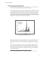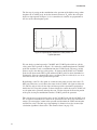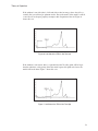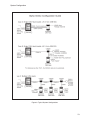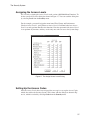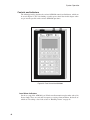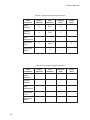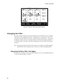
1
Alpha Sentry CAM System User’s Manual V3.0 9231204G Copyright 2005, Canberra Industries, Inc. All rights reserved. The material in this document, including all information, pictures, graphics and text, is the property of Canberra Industries, Inc. and is protected by U.S. copyright laws and international copyright conventions. Canberra expressly grants the purchaser of this product the right to copy any material in this document for the purchaser’s own use, including as part of a submission to regulatory or legal authorities pursuant to the purchaser’s legitimate business needs. No material in this document may be copied by any third party, or used for any commercial purpose, or for any use other than that granted to the purchaser, without the written permission of Canberra Industries, Inc. Canberra Industries, 800 Research Parkway, Meriden, CT 06450 Tel: 203-238-2351 FAX: 203-235-1347 http://www.canberra.com The information in this document describes the product as accurately as possible, but is subject to change without notice. Printed in the United States of America. PIPS are registered trademarks of Canberra Industries, Inc. Windows is trademarks or registered trademarks of Microsoft Corporation in the United States and/or other countries. Millipore is a register trademark of Millipore Corporation Table of Contents Preface · · · · · · · · · · · · · · · · · · · · · · · · · · · · · · · · · · ix 1. Introduction . . . . . . . . . . . . . . . . . . . . . . . . . . . . . . 1 Theory of Operation . . . . . . . . . . . . . . . . . . . . . . . . . . . . . . . . . . . . . . . . . . 2 Alpha Sentry Operating Philosophy . . . . . . . . . . . . . . . . . . . . . . . . . . . . . . . . 2 The Radon Rejection Screen . . . . . . . . . . . . . . . . . . . . . . . . . . . . . . . . . . . . 3 Chronic Release Determination . . . . . . . . . . . . . . . . . . . . . . . . . . . . . . . . . . 5 Acute Release Determination . . . . . . . . . . . . . . . . . . . . . . . . . . . . . . . . . . . 7 Setting the Transuranic Region . . . . . . . . . . . . . . . . . . . . . . . . . . . . . . . . . . 8 Automatic Energy Calibration . . . . . . . . . . . . . . . . . . . . . . . . . . . . . . . . . . 10 2. Installation . . . . . . . . . . . . . . . . . . . . . . . . . . . . . . 12 System Configuration . . . . . . . . . . . . . . . . . . . . . . . . . . . . . . . . . . . . . . . . 12 Configuring the Sampling Head . . . . . . . . . . . . . . . . . . . . . . . . . . . . . . . . . 12 Wall Mounting the Units . . . . . . . . . . . . . . . . . . . . . . . . . . . . . . . . . . . . . 14 Communications . . . . . . . . . . . . . . . . . . . . . . . . . . . . . . . . . . . . . . . . . . . 17 Providing an Air Flow . . . . . . . . . . . . . . . . . . . . . . . . . . . . . . . . . . . . . . . . 19 Connection to Alarms . . . . . . . . . . . . . . . . . . . . . . . . . . . . . . . . . . . . . . . . 19 RS-232 Connections . . . . . . . . . . . . . . . . . . . . . . . . . . . . . . . . . . . . . . . . . 20 Standalone Sampling Head Operation . . . . . . . . . . . . . . . . . . . . . . . . . . . . . . . . 21 External Setup . . . . . . . . . . . . . . . . . . . . . . . . . . . . . . . . . . . . . . . . . . . . 22 The Factory Defaults . . . . . . . . . . . . . . . . . . . . . . . . . . . . . . . . . . . . . . . . . 23 Alarm Annunciation Defaults . . . . . . . . . . . . . . . . . . . . . . . . . . . . . . . . . . 23 The ASM1000 Annunciators . . . . . . . . . . . . . . . . . . . . . . . . . . . . . . . . . 23 The CAM Sampling Head Annunciators . . . . . . . . . . . . . . . . . . . . . . . . . . . 26 Security System Defaults . . . . . . . . . . . . . . . . . . . . . . . . . . . . . . . . . . . . . 28 CAM IDs . . . . . . . . . . . . . . . . . . . . . . . . . . . . . . . . . . . . . . . . . . . . . 28 Alarm Parameter Defaults . . . . . . . . . . . . . . . . . . . . . . . . . . . . . . . . . . . . 28 Installing the Setup Software. . . . . . . . . . . . . . . . . . . . . . . . . . . . . . . . . . . . . 29 The Software . . . . . . . . . . . . . . . . . . . . . . . . . . . . . . . . . . . . . . . . . . . 29 The ASM1000 Connection . . . . . . . . . . . . . . . . . . . . . . . . . . . . . . . . . . . . 29 Performing an External Setup . . . . . . . . . . . . . . . . . . . . . . . . . . . . . . . . . . . . 31 Setting the PC’s Communications Parameters . . . . . . . . . . . . . . . . . . . . . . . . . . 31 Starting the Program . . . . . . . . . . . . . . . . . . . . . . . . . . . . . . . . . . . . . . . 32 The Display Screen . . . . . . . . . . . . . . . . . . . . . . . . . . . . . . . . . . . . . . . . 33 Alarm Annunciation . . . . . . . . . . . . . . . . . . . . . . . . . . . . . . . . . . . . . . . . . 33 The ASM1000 Annunciators . . . . . . . . . . . . . . . . . . . . . . . . . . . . . . . . . . . 33 The Sampling Head Annunciators . . . . . . . . . . . . . . . . . . . . . . . . . . . . . . . . 34 The Security System . . . . . . . . . . . . . . . . . . . . . . . . . . . . . . . . . . . . . . . . . 35 Assigning the Access Levels . . . . . . . . . . . . . . . . . . . . . . . . . . . . . . . . . . . 37 Setting Up the Access Codes . . . . . . . . . . . . . . . . . . . . . . . . . . . . . . . . . . . 37 Completing the Operation . . . . . . . . . . . . . . . . . . . . . . . . . . . . . . . . . . . . 39 Entering the CAM ID Labels. . . . . . . . . . . . . . . . . . . . . . . . . . . . . . . . . . . . . 39 Establishing the CAM Alarm Parameters . . . . . . . . . . . . . . . . . . . . . . . . . . . . . . 40 Restoring the Network . . . . . . . . . . . . . . . . . . . . . . . . . . . . . . . . . . . . . . . . 42 Setup Commands . . . . . . . . . . . . . . . . . . . . . . . . . . . . . . . . . . . . . . . . . . . 42 3. System Operation . . . . . . . . . . . . . . . . . . . . . . . . . . 43 What You Need to Do First . . . . . . . . . . . . . . . . . . . . . . . . . . . . . . . . . . . . . 43 A Guided Tour . . . . . . . . . . . . . . . . . . . . . . . . . . . . . . . . . . . . . . . . . . . . 44 The CAM Sampling Head . . . . . . . . . . . . . . . . . . . . . . . . . . . . . . . . . . . . 44 Controls and Indicators. . . . . . . . . . . . . . . . . . . . . . . . . . . . . . . . . . . . 45 Sampling Head Connectors . . . . . . . . . . . . . . . . . . . . . . . . . . . . . . . . . 46 The Alpha Sentry Manager . . . . . . . . . . . . . . . . . . . . . . . . . . . . . . . . . . . . 47 Controls and Indicators. . . . . . . . . . . . . . . . . . . . . . . . . . . . . . . . . . . . 48 Numeric Keypad Conventions . . . . . . . . . . . . . . . . . . . . . . . . . . . . . . . . 50 ASM1000 Connectors . . . . . . . . . . . . . . . . . . . . . . . . . . . . . . . . . . . . 51 The Network Display. . . . . . . . . . . . . . . . . . . . . . . . . . . . . . . . . . . . . 52 Log In and Log Out . . . . . . . . . . . . . . . . . . . . . . . . . . . . . . . . . . . . . . . . . 54 The Access Code . . . . . . . . . . . . . . . . . . . . . . . . . . . . . . . . . . . . . . . . . 54 System Security. . . . . . . . . . . . . . . . . . . . . . . . . . . . . . . . . . . . . . . . . . 55 Changing the Access Code . . . . . . . . . . . . . . . . . . . . . . . . . . . . . . . . . . . . 56 Logging In . . . . . . . . . . . . . . . . . . . . . . . . . . . . . . . . . . . . . . . . . . . . 56 Logging Out . . . . . . . . . . . . . . . . . . . . . . . . . . . . . . . . . . . . . . . . . . . 57 Configuring the System Network . . . . . . . . . . . . . . . . . . . . . . . . . . . . . . . . . . 58 Automatic Configuration . . . . . . . . . . . . . . . . . . . . . . . . . . . . . . . . . . . . . 58 Manual Configuration . . . . . . . . . . . . . . . . . . . . . . . . . . . . . . . . . . . . . . 59 ii Deleting Sampling Heads . . . . . . . . . . . . . . . . . . . . . . . . . . . . . . . . . . 59 Adding Sampling Heads . . . . . . . . . . . . . . . . . . . . . . . . . . . . . . . . . . . 61 Using the New Configuration . . . . . . . . . . . . . . . . . . . . . . . . . . . . . . . . 62 Handling Alarms . . . . . . . . . . . . . . . . . . . . . . . . . . . . . . . . . . . . . . . . . . . 62 Types of Alarms . . . . . . . . . . . . . . . . . . . . . . . . . . . . . . . . . . . . . . . . . 65 Acute Release . . . . . . . . . . . . . . . . . . . . . . . . . . . . . . . . . . . . . . . . 65 Chronic Release . . . . . . . . . . . . . . . . . . . . . . . . . . . . . . . . . . . . . . . 66 High Background. . . . . . . . . . . . . . . . . . . . . . . . . . . . . . . . . . . . . . . 66 Instrument Fault . . . . . . . . . . . . . . . . . . . . . . . . . . . . . . . . . . . . . . . 67 Acknowledging Alarms. . . . . . . . . . . . . . . . . . . . . . . . . . . . . . . . . . . . . . 68 Viewing System Data . . . . . . . . . . . . . . . . . . . . . . . . . . . . . . . . . . . . . . . . 68 The Detailed Display . . . . . . . . . . . . . . . . . . . . . . . . . . . . . . . . . . . . . . . 68 The Alarm Log . . . . . . . . . . . . . . . . . . . . . . . . . . . . . . . . . . . . . . . . . . 71 Viewing Sampling Head Data . . . . . . . . . . . . . . . . . . . . . . . . . . . . . . . . . . 72 Selecting the Sampling Head to View . . . . . . . . . . . . . . . . . . . . . . . . . . . . 72 Looking at the Data . . . . . . . . . . . . . . . . . . . . . . . . . . . . . . . . . . . . . 73 History Trends . . . . . . . . . . . . . . . . . . . . . . . . . . . . . . . . . . . . . . . . . . 74 Selecting the Sampling Head to View . . . . . . . . . . . . . . . . . . . . . . . . . . . . 74 Selecting the Data Type . . . . . . . . . . . . . . . . . . . . . . . . . . . . . . . . . . . 74 Viewing the Trend Data . . . . . . . . . . . . . . . . . . . . . . . . . . . . . . . . . . . 76 Viewing the Detail Data . . . . . . . . . . . . . . . . . . . . . . . . . . . . . . . . . . . 77 Controlling a Sampling Head . . . . . . . . . . . . . . . . . . . . . . . . . . . . . . . . . . . . 78 Selecting the Sampling Head . . . . . . . . . . . . . . . . . . . . . . . . . . . . . . . . . . . 79 Sampling Head Operations . . . . . . . . . . . . . . . . . . . . . . . . . . . . . . . . . . . . 80 Viewing the Spectrum . . . . . . . . . . . . . . . . . . . . . . . . . . . . . . . . . . . . 80 Manual Start/Stop . . . . . . . . . . . . . . . . . . . . . . . . . . . . . . . . . . . . . . 81 Manual Clear Data . . . . . . . . . . . . . . . . . . . . . . . . . . . . . . . . . . . . . . 81 Returning the Sampling Head to the Network . . . . . . . . . . . . . . . . . . . . . . . . . . 81 Changing the Filter . . . . . . . . . . . . . . . . . . . . . . . . . . . . . . . . . . . . . . . . . . 82 Preparing the New Filter Cartridges . . . . . . . . . . . . . . . . . . . . . . . . . . . . . . . 82 Preparing the Network for the Change . . . . . . . . . . . . . . . . . . . . . . . . . . . . . . 84 Changing the Filter Cartridges . . . . . . . . . . . . . . . . . . . . . . . . . . . . . . . . . . 85 Returning the System to Service . . . . . . . . . . . . . . . . . . . . . . . . . . . . . . . . . 87 iii Setting the Date and Time . . . . . . . . . . . . . . . . . . . . . . . . . . . . . . . . . . . . 87 Checking System Performance. . . . . . . . . . . . . . . . . . . . . . . . . . . . . . . . . . . . 88 Preparing the CAM Network for the Test . . . . . . . . . . . . . . . . . . . . . . . . . . . . 89 The Performance Test . . . . . . . . . . . . . . . . . . . . . . . . . . . . . . . . . . . . . . 90 Returning the System to Service . . . . . . . . . . . . . . . . . . . . . . . . . . . . . . . . . 92 Modifying the System’s Parameters . . . . . . . . . . . . . . . . . . . . . . . . . . . . . . . . . 93 Parameter Setup. . . . . . . . . . . . . . . . . . . . . . . . . . . . . . . . . . . . . . . . . . 93 Alarm Limits Parameters . . . . . . . . . . . . . . . . . . . . . . . . . . . . . . . . . . . 94 Units Parameters . . . . . . . . . . . . . . . . . . . . . . . . . . . . . . . . . . . . . . . 97 Communication Parameters . . . . . . . . . . . . . . . . . . . . . . . . . . . . . . . . . 98 Miscellaneous Parameters. . . . . . . . . . . . . . . . . . . . . . . . . . . . . . . . . . 101 Calibration-Due Messages . . . . . . . . . . . . . . . . . . . . . . . . . . . . . . . . . 102 Source Information . . . . . . . . . . . . . . . . . . . . . . . . . . . . . . . . . . . . . . . 103 4. Host Computer Interface . . . . . . . . . . . . . . . . . . . . . . 106 Message Protocol . . . . . . . . . . . . . . . . . . . . . . . . . . . . . . . . . . . . . . . . . . 106 Data Formats . . . . . . . . . . . . . . . . . . . . . . . . . . . . . . . . . . . . . . . . . . 107 Line Turnaround. . . . . . . . . . . . . . . . . . . . . . . . . . . . . . . . . . . . . . . . . 108 Command Protocol . . . . . . . . . . . . . . . . . . . . . . . . . . . . . . . . . . . . . . . 108 Response Protocol . . . . . . . . . . . . . . . . . . . . . . . . . . . . . . . . . . . . . . . . 108 Normal Response Protocol . . . . . . . . . . . . . . . . . . . . . . . . . . . . . . . . . 109 Error Response Protocol . . . . . . . . . . . . . . . . . . . . . . . . . . . . . . . . . . 109 Busy Response Protocol . . . . . . . . . . . . . . . . . . . . . . . . . . . . . . . . . . 110 Checksum . . . . . . . . . . . . . . . . . . . . . . . . . . . . . . . . . . . . . . . . . . . . 110 Commands and Responses . . . . . . . . . . . . . . . . . . . . . . . . . . . . . . . . . . . . . 111 Status Commands (10, 3A, 11, 3B, E1) . . . . . . . . . . . . . . . . . . . . . . . . . . . . . 111 Summary Alarm Status (10) . . . . . . . . . . . . . . . . . . . . . . . . . . . . . . . . 111 Enhanced Summary Alarm Status (3A). . . . . . . . . . . . . . . . . . . . . . . . . . . 112 Detailed CAM Status (11) . . . . . . . . . . . . . . . . . . . . . . . . . . . . . . . . . 115 Read Calculated Data Commands (18, 3B, 19) . . . . . . . . . . . . . . . . . . . . . . . . . 117 Read Limited Calculated Data A (18) . . . . . . . . . . . . . . . . . . . . . . . . . . . 117 Read Limited Calculated Data B (3B) . . . . . . . . . . . . . . . . . . . . . . . . . . . 118 Read Complete Calculated Data (19) . . . . . . . . . . . . . . . . . . . . . . . . . . . . 118 Setup Parameter Commands (20-25) . . . . . . . . . . . . . . . . . . . . . . . . . . . . . . 121 Read ASM Setup Parameters (20) . . . . . . . . . . . . . . . . . . . . . . . . . . . . . 121 iv Read ASM System Parameters (21) . . . . . . . . . . . . . . . . . . . . . . . . . . . . 122 Read CAM Setup Parameters (22) . . . . . . . . . . . . . . . . . . . . . . . . . . . . . 122 Write ASM Setup Parameters (23) . . . . . . . . . . . . . . . . . . . . . . . . . . . . . 123 Write ASM System Parameters (24) . . . . . . . . . . . . . . . . . . . . . . . . . . . . 125 Write CAM Setup Parameters (25) . . . . . . . . . . . . . . . . . . . . . . . . . . . . . 125 Stop Alarm Command (28) . . . . . . . . . . . . . . . . . . . . . . . . . . . . . . . . . . . 126 Read Data Base Commands (30-32) . . . . . . . . . . . . . . . . . . . . . . . . . . . . . . 126 Read Alarm Log (30) . . . . . . . . . . . . . . . . . . . . . . . . . . . . . . . . . . . . 126 Read Trend Data Base Info (31) . . . . . . . . . . . . . . . . . . . . . . . . . . . . . . 128 Read Trend Data Base Contents (32) . . . . . . . . . . . . . . . . . . . . . . . . . . . . 129 Spectral Data Commands (38-39) . . . . . . . . . . . . . . . . . . . . . . . . . . . . . . . . 131 Read Spectral Data (38). . . . . . . . . . . . . . . . . . . . . . . . . . . . . . . . . . . 131 Read Last Alarm Spectral Info (39). . . . . . . . . . . . . . . . . . . . . . . . . . . . . 133 Acute Alarm (29) . . . . . . . . . . . . . . . . . . . . . . . . . . . . . . . . . . . . . . . . 134 Write Acute Limit Multiplier (C3 29) . . . . . . . . . . . . . . . . . . . . . . . . . . . 134 Read Acute Limit Multiplier (D3 29) . . . . . . . . . . . . . . . . . . . . . . . . . . . . 135 Communication Parameters (2A, 2B, 2C, 2D) . . . . . . . . . . . . . . . . . . . . . . . . . 136 Write Number of Retries Parameter (C3 2A) . . . . . . . . . . . . . . . . . . . . . . . . 136 Read Number of Retries Parameter (D3 2A) . . . . . . . . . . . . . . . . . . . . . . . . 136 Write Retry-Wait Parameter (C3 2B) . . . . . . . . . . . . . . . . . . . . . . . . . . . . 137 Read Retry-Wait Parameter (D3 2B) . . . . . . . . . . . . . . . . . . . . . . . . . . . . 137 Write Post-Command Delay Parameter (C3 2C) . . . . . . . . . . . . . . . . . . . . . . 138 Read Post-Command Delay Parameter (D3 2C) . . . . . . . . . . . . . . . . . . . . . . 139 Write Pre-Command Delay Parameter (C3 2D) . . . . . . . . . . . . . . . . . . . . . . 139 Read Post-Command Delay Parameter (D3 2C) . . . . . . . . . . . . . . . . . . . . . . 140 Calibration Warnings (2E, 2F, 30) . . . . . . . . . . . . . . . . . . . . . . . . . . . . . . . 140 Write Calibration Frequency Parameter (C3 2E) . . . . . . . . . . . . . . . . . . . . . . 140 Read Calibration Frequency Parameter (D3 2E) . . . . . . . . . . . . . . . . . . . . . . 141 Write Warn-Ahead Parameter (C3 2F) . . . . . . . . . . . . . . . . . . . . . . . . . . . 142 Read Warn-Ahead Parameter (D3 2F) . . . . . . . . . . . . . . . . . . . . . . . . . . . 142 Write Activate-Trouble-Light Parameter (C3 30) . . . . . . . . . . . . . . . . . . . . . 143 Read Activate-Trouble-Light Parameter (D3 30) . . . . . . . . . . . . . . . . . . . . . . 143 ASM1000 Communications Setup . . . . . . . . . . . . . . . . . . . . . . . . . . . . . . . . . 144 System Configuration . . . . . . . . . . . . . . . . . . . . . . . . . . . . . . . . . . . . . . . . 146 v Model ASM01 (RS-485) . . . . . . . . . . . . . . . . . . . . . . . . . . . . . . . . . . . . 146 Model ASM02 (RS-232C) . . . . . . . . . . . . . . . . . . . . . . . . . . . . . . . . . . . 148 Field Installation . . . . . . . . . . . . . . . . . . . . . . . . . . . . . . . . . . . . . . . . . . 148 Completing the Installation . . . . . . . . . . . . . . . . . . . . . . . . . . . . . . . . . . . 151 Installing the Configuration and Firmware Upgrade Software . . . . . . . . . . . . . . . . . . . 151 The S579 Software . . . . . . . . . . . . . . . . . . . . . . . . . . . . . . . . . . . . . . . 151 Downloading Interface Parameters . . . . . . . . . . . . . . . . . . . . . . . . . . . . . . . . . 152 A. Algorithms . . . . . . . . . . . . . . . . . . . . . . . . . . . . . 157 Calibration . . . . . . . . . . . . . . . . . . . . . . . . . . . . . . . . . . . . . . . . . . . . . 157 Energy Calibration . . . . . . . . . . . . . . . . . . . . . . . . . . . . . . . . . . . . . . . 157 Efficiency Calibration . . . . . . . . . . . . . . . . . . . . . . . . . . . . . . . . . . . . . . 157 Flow Calibration. . . . . . . . . . . . . . . . . . . . . . . . . . . . . . . . . . . . . . . . . 158 Spectrum Analysis . . . . . . . . . . . . . . . . . . . . . . . . . . . . . . . . . . . . . . . . . 159 Automatic Energy Recalibration . . . . . . . . . . . . . . . . . . . . . . . . . . . . . . . . 159 Background Compensation . . . . . . . . . . . . . . . . . . . . . . . . . . . . . . . . . . . 161 Analysis Results . . . . . . . . . . . . . . . . . . . . . . . . . . . . . . . . . . . . . . . . . 166 Alarm Logic. . . . . . . . . . . . . . . . . . . . . . . . . . . . . . . . . . . . . . . . . . . . . 170 The Acute Alarm . . . . . . . . . . . . . . . . . . . . . . . . . . . . . . . . . . . . . . . . 170 The Chronic Alarm . . . . . . . . . . . . . . . . . . . . . . . . . . . . . . . . . . . . . . . 170 The High Background Alarm . . . . . . . . . . . . . . . . . . . . . . . . . . . . . . . . . . 171 B. Technical Reference . . . . . . . . . . . . . . . . . . . . . . . . 172 Setup Command Protocol . . . . . . . . . . . . . . . . . . . . . . . . . . . . . . . . . . . . . . 172 Setup Interface Commands and Responses . . . . . . . . . . . . . . . . . . . . . . . . . . . . . 174 Set Alarm Template . . . . . . . . . . . . . . . . . . . . . . . . . . . . . . . . . . . . . . . 174 Read Alarm Template . . . . . . . . . . . . . . . . . . . . . . . . . . . . . . . . . . . . . . 177 Set Variable . . . . . . . . . . . . . . . . . . . . . . . . . . . . . . . . . . . . . . . . . . . 178 Read Variable . . . . . . . . . . . . . . . . . . . . . . . . . . . . . . . . . . . . . . . . . . 180 Set Access Range . . . . . . . . . . . . . . . . . . . . . . . . . . . . . . . . . . . . . . . . 181 Read Access Range . . . . . . . . . . . . . . . . . . . . . . . . . . . . . . . . . . . . . . . 182 Set Menu Access Length . . . . . . . . . . . . . . . . . . . . . . . . . . . . . . . . . . . . 183 Read Menu Access Length . . . . . . . . . . . . . . . . . . . . . . . . . . . . . . . . . . . 183 Set Menu Protection . . . . . . . . . . . . . . . . . . . . . . . . . . . . . . . . . . . . . . . 184 Read Menu Protection . . . . . . . . . . . . . . . . . . . . . . . . . . . . . . . . . . . . . . 187 vi Reset Data Available . . . . . . . . . . . . . . . . . . . . . . . . . . . . . . . . . . . . . . 187 Read Summary Alarm Status . . . . . . . . . . . . . . . . . . . . . . . . . . . . . . . . . . 188 Read Enhanced Summary Alarm Status . . . . . . . . . . . . . . . . . . . . . . . . . . . . 188 Set Display Flag . . . . . . . . . . . . . . . . . . . . . . . . . . . . . . . . . . . . . . . . . 189 Read Limited Calculated Data2 . . . . . . . . . . . . . . . . . . . . . . . . . . . . . . . . . 190 Read Flow . . . . . . . . . . . . . . . . . . . . . . . . . . . . . . . . . . . . . . . . . . . . 191 Read Raw CPM . . . . . . . . . . . . . . . . . . . . . . . . . . . . . . . . . . . . . . . . . 191 C. Maintenance . . . . . . . . . . . . . . . . . . . . . . . . . . . . 193 Calibration . . . . . . . . . . . . . . . . . . . . . . . . . . . . . . . . . . . . . . . . . . . . . 193 Sampling Head Energy Calibration . . . . . . . . . . . . . . . . . . . . . . . . . . . . . . . 193 Efficiency Calibration . . . . . . . . . . . . . . . . . . . . . . . . . . . . . . . . . . . . . . 193 CAM Air Flow Calibration . . . . . . . . . . . . . . . . . . . . . . . . . . . . . . . . . . . 197 Information and Error Messages . . . . . . . . . . . . . . . . . . . . . . . . . . . . . . . . . . 198 Information Messages . . . . . . . . . . . . . . . . . . . . . . . . . . . . . . . . . . . . . . 199 Error Messages . . . . . . . . . . . . . . . . . . . . . . . . . . . . . . . . . . . . . . . . . 199 Alarms and Alarm Messages . . . . . . . . . . . . . . . . . . . . . . . . . . . . . . . . . . 201 CAM Fault Octal Values . . . . . . . . . . . . . . . . . . . . . . . . . . . . . . . . . . 202 ASM1000 Fault Octal Values. . . . . . . . . . . . . . . . . . . . . . . . . . . . . . . . 203 Alarm Messages. . . . . . . . . . . . . . . . . . . . . . . . . . . . . . . . . . . . . . . 205 Other Alarm Messages . . . . . . . . . . . . . . . . . . . . . . . . . . . . . . . . . . . 206 Preventive Maintenance. . . . . . . . . . . . . . . . . . . . . . . . . . . . . . . . . . . . . . . 207 Weekly Maintenance . . . . . . . . . . . . . . . . . . . . . . . . . . . . . . . . . . . . . . 207 Biannual Preventive Maintenance. . . . . . . . . . . . . . . . . . . . . . . . . . . . . . . . 208 Annual Preventive Maintenance . . . . . . . . . . . . . . . . . . . . . . . . . . . . . . . . 209 Self-Diagnostics . . . . . . . . . . . . . . . . . . . . . . . . . . . . . . . . . . . . . . . . . 209 Other Diagnostics . . . . . . . . . . . . . . . . . . . . . . . . . . . . . . . . . . . . . . . . 210 Cleaning Procedures . . . . . . . . . . . . . . . . . . . . . . . . . . . . . . . . . . . . . . . . 213 ASM1000 . . . . . . . . . . . . . . . . . . . . . . . . . . . . . . . . . . . . . . . . . . . . 213 Sampling Head . . . . . . . . . . . . . . . . . . . . . . . . . . . . . . . . . . . . . . . . . 214 Cleaning the PIPS Detector . . . . . . . . . . . . . . . . . . . . . . . . . . . . . . . . . . . 214 Disassembly and Reassembly. . . . . . . . . . . . . . . . . . . . . . . . . . . . . . . . . . . . 215 ASM1000 . . . . . . . . . . . . . . . . . . . . . . . . . . . . . . . . . . . . . . . . . . . . 215 Sampling Head . . . . . . . . . . . . . . . . . . . . . . . . . . . . . . . . . . . . . . . . . 215 MCA. . . . . . . . . . . . . . . . . . . . . . . . . . . . . . . . . . . . . . . . . . . . . . . 216 vii Upper Housing . . . . . . . . . . . . . . . . . . . . . . . . . . . . . . . . . . . . . . . . . 216 Firmware Update and Acute Test Option . . . . . . . . . . . . . . . . . . . . . . . . . . . . . . 220 Installing the Model S579 . . . . . . . . . . . . . . . . . . . . . . . . . . . . . . . . . . . . 220 Field Installing the Alarm Option. . . . . . . . . . . . . . . . . . . . . . . . . . . . . . . . . . 223 Checking for Proper Operation . . . . . . . . . . . . . . . . . . . . . . . . . . . . . . . . . 223 Configuring the Annunciators . . . . . . . . . . . . . . . . . . . . . . . . . . . . . . . . . . 224 The In-Line Manifold . . . . . . . . . . . . . . . . . . . . . . . . . . . . . . . . . . . . . . . . 224 Sampling Pipe Connection . . . . . . . . . . . . . . . . . . . . . . . . . . . . . . . . . . . 224 Repositioning the Intake Pipe . . . . . . . . . . . . . . . . . . . . . . . . . . . . . . . . . . 225 Removing the Seal Ring . . . . . . . . . . . . . . . . . . . . . . . . . . . . . . . . . . 226 Installing the AS010 In-Line Manifold . . . . . . . . . . . . . . . . . . . . . . . . . . . . . 227 Removing the Model AS020 Alarm . . . . . . . . . . . . . . . . . . . . . . . . . . . . 228 AS010 Installation Procedure . . . . . . . . . . . . . . . . . . . . . . . . . . . . . . . . 228 Reinstalling the AS020 Alarm . . . . . . . . . . . . . . . . . . . . . . . . . . . . . . . . . . . 232 Connectors and Signals . . . . . . . . . . . . . . . . . . . . . . . . . . . . . . . . . . . . . . . 233 ASM1000 . . . . . . . . . . . . . . . . . . . . . . . . . . . . . . . . . . . . . . . . . . . . 233 Sampling Head . . . . . . . . . . . . . . . . . . . . . . . . . . . . . . . . . . . . . . . . . 238 Specifications . . . . . . . . . . . . . . . . . . . . . . . . . . . . . . . . . . . . . . . . . . . . 241 D. FCC Notices. . . . . . . . . . . . . . . . . . . . . . . . . . . . . 249 Index . . . . . . . . . . . . . . . . . . . . . . . . . . . . . . . . . . 251 Menu Flow Chart · · · · · · · · · · · · · · · · · · · · · · · · · · · · 251 viii Preface Canberra’s Alpha Sentry Continuous Air Monitor (CAM) System, the most advanced continuous air monitor on the market today, gives you: • Increased confidence by eliminating false alarms due to radon • Increased sensitivity and decreased cost per sampling location • Increased safety – with up to eight sampling heads operated from a single controller, an entire room can be monitored for a potential release from a point safely outside the room. About This Manual This manual’s four chapters cover Introduction to the system, Installation, System Operation, and the optional Host Computer Interface. In addition, there are four appendices, Algorithms, Technical Reference, Maintenance and FCC Notices. Typographic Conventions The following typographic conventions will be used throughout this manual: SMALL CAPITALS Small capital letters indicate the names of the controls, connectors, and keypad keys, such as ENTER or CLEAR. boldface Boldface type refers to messages or items on the ASM1000’s display. ix Notes x 1. Introduction The Alpha Sentry Continuous Air Monitor (CAM) System resolves many of the issues facing Alpha CAM users today, such as false alarms due to radon, sensitivity, safety of personnel and cost per sampling location. It addresses the problem of false alarms due to varying concentrations of radon decay progeny with a two-fold approach: physical removal through a patented radon rejection screen, and mathematical subtraction of the remainder with a stripping algorithm. Compensation for radon daughters not only lowers the false alarm rate, it also increases sensitivity. Increased safety of personnel is assured by the distributed architecture of the Alpha Sentry. With up to eight sampling heads operated from a single ASM1000 controller, a large facility can be monitored in safety from a remote station. Sharing the controller also lowers the cost per sampling location. In addition, networking to a laboratory-wide computer is easier – only one network connection is required for eight sampling heads. Each sampling head has a two-fold function in the Alpha Sentry System. The first is to collect airborne particulates onto an internal filter and detect any alpha radiation present. The second is to determine the occurrence of an acute release. The air is drawn into the sampling head through the radon rejection screen and through the filter by way of a vacuum connection. A PIPS ® (Passivated Implanted Planar Silicon) radiation detector is positioned above the filter to detect the alpha radiation. Signal processing electronics, which includes a multichannel analyzer, are used to collect and store the alpha spectra. Figure 1 shows a cross-section diagram of the sampling head. The ASM1000 provides the operator interface for up to eight of these sampling heads. It consists of an LCD display and a pushbutton front panel, housed in a rugged metal case. Its function in the system is to periodically read out the spectrum from each sampling head (at a time interval selected by the user), apply a sophisticated background stripping algorithm, and determine the occurrence of a chronic release. A discussion of how the system determines the acute and chronic releases, and how it performs background stripping, is described in the next section, “Theory of Operation”. For a more technical discussion, refer to Appendix A, Algorithms. Introduction Figure 1 Cross Section of a Sampling Head Theory of Operation This section of the manual is intended to give you an idea of what’s going on “behind the scenes” in the Alpha Sentry System. It discusses the operating philosophy of the Alpha Sentry System, the determination of release alarms, the physics behind the radon rejection screen, the stripping algorithm and the automatic energy recalibration. It is not intended to give step-by-step guidance in operating the system, which is covered in Chapter 3, System Operation. It also does not contain the equations used in the calculations. Those are covered in Appendix A, Algorithms. Alpha Sentry Operating Philosophy Alpha air monitoring presents difficulties due to the fact that small amounts of transuranic particulates need to be determined in the presence of large amounts of radon daughter products. The Alpha Sentry has been designed to minimize the impact of the radon progeny in the sample. 2 Theory of Operation Each Sampling Head continuously collects data into its multichannel analyzer. This data is constantly monitored for the presence of an acute release, as explained in “Acute Release Determination” on page 7. Periodically, at a time preset by the user, the ASM1000 reads out the spectrum from each Sampling Head, applies a background stripping algorithm, and determines if a chronic release has occurred. Canberra recommends that this “cycle count time” be at least 15-30 minutes for reasonable counting statistics, better sensitivity and fewer false alarms. When the spectrum is read out, the MCA’s memory is erased and a new count cycle begins. By erasing the spectrum, we are reducing the background so that any radon progeny that have already decayed will not be seen in the next spectrum. Any transuranic activity on the filter will remain in the next spectrum, since for all practical purposes it does not decay. It is important to note that you do not have to wait until the end of a count cycle to be no tified of an acute release. At a user-selected interval, which by default is 30 seconds, the Sampling Head calculates a ratio that determines whether an acute release has occurred, based on the counts seen within the last interval. If an acute alarm condition is indicated, the head notifies the ASM1000, which will terminate the count cycle and turn on appropriate annunciators on the head and on the ASM1000. The ASM1000 will also read out the spectrum and place it in the “Last Alarm Spectrum” register, as well as perform all the usual calculations associated with a readout. If the head is no longer connected to an ASM1000, the head will continue to monitor based on the last settings from the ASM1000 and turn on its own annunciators if an acute alarm condition is detected. Any spectrum that causes an acute or chronic release alarm is saved by the CAM Head as the “Last Alarm Spectrum”, which can be displayed at any time through the ASM1000 for close examination. The other alarm condition that may be saved as “Last Alarm Spectra” is High Background. Each Sampling Head has only one “Last Alarm Spectrum”, which is the last one that caused an alarm. Spectra which caused earlier alarms are not saved, although the results of the last 50 alarms with their date and time of occurrence are available in the Alarm Log and individual results are saved in each Sampling Head’s database. The Radon Rejection Screen The radon rejection screen in the Sampling Head of Canberra’s Alpha Sentry CAM is a patented physical approach to dealing with radon progeny in the environment. The screen is effective at removing from the sampled air up to 95% of unattached (newly formed) radon progeny that would otherwise pass into the sampling head and deposit on the filter medium. Plutonium and uranium particulates as well as attached (aged) radon progeny pass through the screen and collect on the filter. 3 Introduction Since some radon progeny do deposit on the filter, the instrument must compensate them. This is accomplished with Canberra’s unique spectrum stripping algorithm, which together with the radon rejection screen, significantly increases Alpha Sentry’s detection sensitivity, particularly in environments with high levels of unattached radon progeny. Unattached radon progeny have not been in the environment long enough to attach to other progeny, to water molecules or to particles of dust. They are quite small (between 1 and 10 nm diameter) relative to other molecules in the air and they diffuse through the air in rather tortuous paths reminiscent of Brownian motion as a result of multiple random collisions. The radon rejection screen works by adsorbing the chemically reactive unattached radon progeny. The important dimensions of the screen (160 µm diameter holes in 50 µm thick stainless steel) are such that, under the recommended air flow rates, there is a very high probability that the unattached radon progeny will collide with and be adsorbed by the inner surface of the passages through the screen. Plutonium and uranium particulates, as well as attached radon progeny, are much larger on average than unattached progeny (between 1 µm and 10 µm). Because of their larger size and greater mass, their paths through the air are less Brownian in nature and can be described as more ballistic. In addition to being larger, these particulates are less chemically reactive than unattached progeny, and thus less likely to collide with and be adsorbed by the inner surface of the holes in the screen. All particulates that pass through the screen are collected on the filter. Since attached radon progeny that deposit on the filter can interfere with the detection and analysis of airborne plutonium or uranium particulates, a sophisticated algorithm is used to analyze the spectrum and compensate for the background due to radon progeny. There are times when one may consider operating the Alpha Sentry CAM sampling heads without the radon rejection screen in place. This can be an acceptable mode of operation in some situations since any radon progeny, attached or unattached, that deposit on the filter medium are dealt with by the background compensation algorithm. This mode of operation can be considered when the monitored environment has a high dust level, requiring frequent cleaning of the screen to remove debris. But some words of caution are in order. In an environment with high dust levels, it is common for the fraction of attached radon progeny to dominate over the unattached fraction, but one cannot assume this to be the case without carefully examining the air exchange characteristics of that environment. If there is sufficient air exchange, the fraction of unattached radon progeny may be higher than expected. In such a case the radon rejection screen would have some value, regardless of the dust level. High dust level alone is not sufficient to determine the fraction of attached radon progeny. Time and the air exchange rate are also very important. 4 Theory of Operation Chronic Release Determination The primary difficulty in determining whether a chronic release has occurred is the interference from the radon daughters in the transuranic (TRU) region. As can be seen in Figure 2, each of the three radon daughter peaks (6.05 MeV1, 7.68 MeV and 8.78 MeV) have a pronounced tail, which is caused by several factors. First of all, by counting alpha particles in air, you get some energy degradation because the alpha particles collide with air molecules on their way to the detector and lose some energy. Some alphas will lose their energy just by passing through the entrance window of the detector, particularly those entering at an angle. Finally, filter loading over time causes sample self absorption: the sample itself will attenuate some of the alphas. Figure 2 Radon Daughter Peak Tails These tails reach down into the energy region where we expect to see plutonium (5.15 to 5.5 MeV) and uranium (4.6 to 4.8 MeV). Therefore, if we look at the Pu or U regions, there are counts due to Pu or U, as well as counts due to each of the three radon daughter peaks. Since the three radon daughter peaks overlap, we apply a multiplet stripping method to determine the counts associated with each peak. This method differs from traditional deconvolution algorithms, in that we use a model of the peak tail, rather than a model of the peak itself to fit the data. Each radon daughter peak is looked at in two components: the tail and the peak itself. 1. This represents the 6.00 MeV peak from 218 Po (222Ra) as well as the 6.05 MeV peak from 212Bi (220Ra). 5 Introduction The first step is to strip out the contribution to the spectrum of the highest energy radon daughter: the 8.78 MeV peak. At the first channel of interest, X0 (where the tail region begins to slope upwards in Figure 3), it is assumed that its contents are proportional to the sizes of the radon daughter peaks. Figure 3 Experimentally Determined Valley Points in a Typical Spectrum We now look at a point between the 7.68 MeV and 8.78 MeV peaks which we call the valley point. This is point X 3 in Figure 3. It is where the contribution from the 7.68 MeV peak ends and there is only a contribution from the 8.78 MeV peak. The energy of this point (as well as the other two valley points – X 2 between the 6.05 MeV and 7.68 MeV peaks and X1 between the TRU region and the 6.05 MeV peak) has been determined experimentally. Since we automatically energy recalibrate prior to each analysis, we are assured that we have the correct point in the spectrum. By definition, at the X3 valley point we assume that the counts are only due to the 8.78 MeV peak. Therefore, we now know the counts in the 8.78 MeV tail region at either end (X3 and X0), and can solve for the slope and intercept of the exponential equation that models the tail. Using this equation, we then calculate the counts due to the 8.78 MeV tail at each point in the spectrum, and strip these out. We then strip out the Gaussian portion of the peak, leaving no contribution from the 8.78 MeV peak in the spectrum. This same process is repeated twice more, for the 7.68 MeV peak and the 6.05 MeV peak. We are now left with only those counts in the spectrum that are due to any transuranic elements. We sum up these counts in the spectrum and determine the CPM, concentration and DAC-hr values. The final step is determining if a chronic release has occurred (the calculation algorithm is discussed in “The Chronic Alarm” on page 170). 6 Theory of Operation Acute Release Determination An acute release is determined at the Sampling Head, where the MCA looks for either excessive counts or excessive change in counts in the transuranic (TRU) region. The behavior of the Head’s embedded acute algorithm is modified by the alarm method selected at the controller. When the alarm method is set for DAC-Hr mode the algorithm looks for excessive counts in the TRU region. When the alarm method is set for DAC mode the algorithm looks for excessive change in counts in the TRU region. Either the average counts per channel or the delta in the average counts per channel in the TRU region (that is, plutonium or uranium) are compared to the equivalent values in the background region from the end of the TRU window to the 6.05 MeV peak at 30 second (user-selected) intervals (Figure 4). Figure 4 The TRU Region vs. the Background Region If this ratio (TRU to background) is greater than 2, and the sum of the counts in the TRU region are greater than 80 (user-selected), an acute release is annunciated. (Setting the acute alarm minimum count limit is covered in “Acute Alarm Minimum Count Limit” on page 28.) The qualifier of 80 counts prevents false alarms. If there were no qualifier, the unit would give an alarm with only two counts in the TRU region and a single count in the “background” region, which is obviously not an acute condition. It must be kept in mind that this is a gross determination. If there is in fact an acute release, there will be far more than 80 counts in the TRU region, and the ratio of TRU to “background” counts would far exceed two. The regions are continuously adjusted based on the automatic energy recalibration (described on page 10). This continuous recalibration ensures that the correct region is used in spite of any peak shifts that will occur due to attenuation from filter loading over time. 7 Introduction Since the determination of an Acute Release is the most important function of an Alpha Sampling Head, we have taken steps to ensure that even if the ASM1000 is off-line for any reason, the Sampling Head can still determine an acute release and annunciate its alarms. There are default regions that are programmed in the Head which are used in the absence of the ASM1000. Setting the Transuranic Region The transuranic, or analysis, region is set by the user through the ASM1000 Operator Interface. It is important to realize that this is not a Region of Interest (ROI), which is normally meant to define a peak area. It is simply a broad region which encompasses the peak of interest, but is not necessarily defined by it. In the ASM1000, these limits are defined as the Upper Energy Cutoff and the Analysis Window. The Upper Energy Cutoff is the right-hand limit of the region, and is specified in MeV. It should be set slightly above the energy of the highest energy transuranic. For instance, if you’re looking for 239Pu at 5.15 MeV, you should set the Upper Energy Cutoff at 5.7 MeV (which is the default setting). If the region is set too high, so that it is quite close to the 6.05 MeV radon daughter peak, you will have greater uncertainty in the calculated results. The Analysis Window is the window width, in MeV, which defines the left-hand limit of the TRU region (the Upper Energy Cutoff setting minus the Analysis Window setting equals the left-hand limit). This should be positioned at the point where the counts in the combined tail region begin to slope upwards (X 0 in Figure 5). The default setting of the Analysis Window is 2.7 MeV, which means that the left-hand limit is 3.0 MeV (5.7 MeV – 2.7 MeV = 3.0 MeV). Figure 5 Set Point for the Analysis Window (Left Side of the Transuranic Region) 8 Theory of Operation If the window is too wide (that is, left hand side too low in energy, where the tail is essentially flat) you will not get optimum results. Due to the nature of the model, it will fit a curve that is too sharp to properly encompass this flat portion of the tail. Figure 6 shows this case. Figure 6 Left Side of the TRU is Set Too Low If the window is too narrow, there is a potential that the X 0 valley point will be larger than the other three valley points. Since the model expects this point to be lower, the model will break down. Figure 7 shows this case. Figure 7 Left Side of the TRU is Set Too High 9 Introduction For this reason, it is recommended that you collect a few sample spectra yourself, compare them with the figures presented here, and experiment with different settings to help you determine the optimum settings for your site. The following table lists some recommended default settings. Nuclide of Interest Upper Energy Limit (MeV) Analysis Window (MeV) 239 Pu 5.7 2.7 238 Pu 5.8 2.8 241 Am 5.8 2.8 235 U, 4.7 1.7 238 U* *Note that uranium requires that some default parameters be changed. Refer to “Parameters for Uranium” on page 94. Automatic Energy Calibration Due to filter loading, which causes attenuation, the alpha peaks in the spectrum will tend to shift to lower energy. This becomes more pronounced over time, as the filter becomes more loaded. Thus from the time a new filter is inserted until it is removed, the peak locations are continuously changing. This phenomenon affects all the peaks by approximately the same amount (barring any instrument malfunction). In order to properly apply the background stripping algorithm, we keep track of the peak locations, so that the radon daughter peaks can be stripped from the spectrum. This is done automatically by the ASM1000 with an automatic energy recalibration, which is performed every time a spectrum is analyzed. The energy recalibration is based on the 7.68 MeV peak, normally the most prevalent peak in the spectrum. During the first analysis after a filter change, the peak cannot be more than the user selectable limit of channels (the default is 15) away from its expected location based on the default energy calibration. If the peak is within this limit, a recalibration will take place. For any subsequent analysis, as long as the peak is not found to be more than the user-set number of channels away from its first location after a filter change, and the newly calculated offset is less than 10% different from its previous offset, the recalibration will take place. 10 Theory of Operation During the recalibration, all the peaks in the spectrum will be shifted by the same amount as the 7.68 MeV peak. Once the recalibration is complete, the stripping algorithm is applied. If it is determined that the 7.68 MeV peak has shifted too far for an energy recalibration (due most likely to excessive filter loading), the “Peak Shift Excd.” error message will appear. At this point the energy calibration will not be changed, but the results will still be calculated using the previous energy calibration, and the alarm condition will be noted in the alarm log. 11 Installation 2. Installation This chapter discusses installation of an Alpha Sentry CAM System, which consists of at least one Manager and one Alpha Sentry Sampling Head, and covers the external PC setup procedure. Various system configurations are shown in Figure 8. The ASM1000 Manager is only available in 115 V ac version. System Configuration The ASM1000 system is powered by 115 V ac at 60 Hz ac and is configured at the factory with a 2 m (6 ft) line cord terminated in a NEMA 5-15P Grounding Plug. Configuring the Sampling Head Power to the Sampling Head is approximately 24 volt ac. The ASM1000 can provide this power to one Sampling Head within 45 m (150 ft). Each ASM1000 is shipped with a 3 m (10 ft) C2003 cable to provide power to one Head. For multiple Heads or those positioned beyond the 45 m limit, there must be a power supply for each head. The Model AS070 Sampling Head Power Supply is used with 115 V ac mains. The three feet on the lower housing are for securing the Head to a mounting surface. The Head will operate in any orientation once a filter cartridge has been put into position. The normal orientation of the lower housing puts the cable connectors under the filter drawer. If your location requires it, the housing is easily rotated by 120 degrees either clockwise or counter-clockwise. This is done by first disconnecting all cables, then removing the three #6 Phillips-head screws on the bottom of the Head and slowly dropping the dark gray metal MCA Assembly from the upper plastic. Now you can rotate the MCA Assembly in either direction to align the holes with the three standoffs. Slide the Assembly into position while taking care not to pinch a wire in the cable, then reinstall the screws. Note that on later units, a base plate with mounting feet is at the bottom of the MCA Assembly. 12 System Configuration Figure 8 Typical System Configurations 13 Installation Wall Mounting the Units Both the ASM1000 and the Sampling Head are factory configured for table top use. Either or both can be mounted on a wall, as described in the following two subsections. If you don’t plan to mount either of the units on the wall at this time, go on to “Communications” on page 17. Wall Mounting the ASM1000 The ASM1000 chassis is shipped in a configuration suitable for table-top operation. The tilt-stand on the back of the ASM1000 can be used to tilt the unit for better viewing. For wall mounting, every ASM1000 is shipped with a set of mounting brackets (Figure 9). To use these, remove the four plastic feet and tilt-stand. Install the bracket on the rear of the ASM using the supplied screws. The brackets for top and bottom are keyed so that the screws in the wall will lock in place, securing the unit to the wall. The wall fasteners are not supplied. The wall fasteners and mounting surface combined must support at minimum four times the weight of the ASM1000, or approximately 17 kg (37 lb). Figure 9 The Wall Mount Bracket 14 System Configuration For wall mounting, it may be preferable to remove the line cord and bring the ac power through an electrical conduit. An easily removable knockout plug on the chassis allows use of a standard ( 1 2 in.) electrician’s wire coupling. The standard line cord is easily removed and your facility’s ac supply cable can be attached to a terminal strip inside the ASM1000. Changing the ASM1000’s Power Wiring Follow these steps to change the ASM1000’s power wiring. WARNING Live power wires can be lethal! Be certain that the facility’s power wires are not carrying electricity before you work with them. 1. Remove the two Phillips-head screws on either side of the chassis. Removing these will allow the top cover to be lifted away from the chassis. 2. This will expose six Phillips pan head screws that secure the LCD/Keyboard to the chassis. 3. Remove these screws and carefully lift the LCD/Keyboard, noting placement of the grounding loop from the keyboard on the left side. 4. Rest the LCD/Keyboard assembly facing down on the right-side of the ASM1000. Be sure to rest the assembly on a soft surface such as cloth to protect the LCD's glass surface. Also, be sure to keep the assembly as close to the ASM1000 as possible to prevent excessive strain on the interconnecting cables. Use a spacer such as a book to lift the LCD/Keyboard assembly if necessary. 5. The ac fuse on the left side is directly connected to the upper terminal. Since the ASM1000 does not have a power switch, it’s a good idea to remove the fuse until you are sure the AC is wired properly and the ASM1000 has been reassembled. 6. The terminal strip on the left of the ASM1000 internal board terminates the line cord, as shown in Figure 10. Loosen the screws holding the lugs on the white and black wires, removing the nuts holding the green wire, and remove the line cord. A small plug is provided to fill the hole. 7. Attach the wires bringing in facility power as shown in Figure 11. Be sure that the green ground wire is longer than the white or black, and attach it under the lower nut of the ground lug. Use at least 300 volt 18 gauge wire for these connections. 15 Installation 8. When equipment is permanently connected, the end-user must supply a switch or circuit breaker in the building installation. This disconnect device must be in close proximity to the equipment and within easy reach of the operator. This device must be marked as the disconnect device for the equipment in question. Figure 10 Line Cord Power Connection Figure 11 Conduit Power Connection 16 Communications 9. Carefully re-install the LCD/Keyboard then use the six smaller screws to fasten the panel to the chassis making sure that the ground strap on the left side loops under the panel with the screw passing through it. 10. Reinstall the top cover using four Phillips-head screws through the holes on the sides. 11. Reinstall fuse if removed in step 5. Wall Mounting the Sampling Head There is an optional Model AS050 Sampling Head Wall Mounting Bracket available. This is to be attached to the wall with user-provided fasteners. The sampling head’s feet are fastened to the bracket’s three studs and secured with the supplied nuts. The wall fasteners and mounting surface combined must support at minimum four times the weight of the Sampling Head, or approximately 8 kg (18 lb). Communications The ASM1000 is linked to up to eight Sampling Heads on a daisy chained RS-485 half-duplexed network. A 3 m (10 ft) C-2000 communications cable is provided with each ASM1000. This can be connected directly to a single Head which will enumerate as CAM #1. RS-485 networks can be extended up to 1200 m (4000 ft) but must be terminated at both ends in the characteristic impedance of the cable. In the Alpha Sentry System, the ASM1000 provides one end of the network and has an internal 120 ohm termination. For a single sampling head within 7.5 m (25 ft), no additional termination is necessary. The recommended cable is a Belden 3105A RS485 Cable or equivalent UL-Listed cable. The signals are on pins 5 and 9. The cable drain wire connects to pin 4 and the cable shield connects to the cable hood (refer to “Connectors and Signals” on page 233 for more information). Network Tee Box For single Head distances greater than 7.5 m (25 ft) or when using multiple Heads, a Model CA2000 Network Tee Box (NTB) must be installed at each Head. Each NTB includes a 3 m (10 ft) C2002 cable to connect the NTB to its Head, and a Terminator to use when it is at the far end. A terminator must be used if the network distance is greater than 7.5 m (25 ft). Either of the connectors on the NTB labeled Network A and Network B can be connected to the ASM1000 or the terminator side of the network. 17 Installation NTB Address Switch The other function of the NTB is to provide a sampling head address which indicates its location on the network. Each sampling head has a unique address that can be read by its ASM1000. The location address is coded by a switch in the NTB. Remove the chrome plated plug on the NTB to access the switch. Each NTB on an ASM1000/sampling head network must have a unique address. The address codes and their switch positions are given in Table 1. The NTB switch can be either a three-pole DIP switch or a rotary switch. For the DIP switch, labels are screened on the PC board identifying the individual poles as 1, 2, and 4 (the DIP switches themselves may identify the poles as 1, 2, and 3). For the rotary switch, the positions may be numbered 0-7 or 1-8. Table 1 NTB Address Setup DIP Switch Pole 1 2 4 Rotary Switch Position 1 OFF* OFF OFF 0 (or 1) 2 ON* OFF OFF 1 (or 2) 3 OFF ON OFF 2 (or 3) 4 ON ON OFF 3 (or 4) 5 OFF OFF ON 4 (or 5) 6 ON OFF ON 5 (or 6) 7 OFF ON ON 6 (or 7) 8 ON ON ON 7 (or 8) CAM # *Some DIP switches may be labeled open instead of off and closed instead of on. Host Computer Interface The optional Host Computer Interface consists of a set of commands allowing a Host Computer to monitor the operation of multiple CAMs and read and write data and various Setup parameters. 18 Providing an Air Flow Installation instructions for this interface will be found in Chapter 4, “Host Computer Interface”. Providing an Air Flow Connection to a vacuum line is necessary to pull air through the Sampling Head to deposit particles on the filter. A 9.5 mm ( 3 8 in.) ID hose is connected to a fitting on the Head. The Head measures the air flow and uses the total volume in its calculations. The factory calibration has been set for: AS450 – 0.5 to 1.5 scfm (14.2 to 42.5 L/min) AS1700 – 1.5 to 2.5 scfm (42.5 to 70.8 L/min) The type of sensor used to measure the air flow requires that the operator enter the altitude and approximate air temperature. The factory default has been set to an altitude of 0 ft (0 m) and a temperature of 298 °K (25 °C). If you need to alter either of these, use the ASM1000 Miscellaneous Parameter menu screen (from the Network Display Screen press F4, then F1, then F4). While totalizing the air flow through the Head, the ASM1000 also checks the air flow to be within alarm limits. The factory defaults for these are: Low flow: 0.5 cfm (14.2 L/min) High flow: 2.5 cfm (70.8 L/min) These limits are set in the Alarm Parameter menu screen (from the Network Display Screen press F4, F1, F1). If it is necessary to recalibrate for a different flow range, refer to “CAM Air Flow Calibration” on page 197. Connection to Alarms Both the ASM1000 and the Sampling Head have relay contacts that are activated upon certain alarm conditions. Connection to these relays is through a six-position terminal board on the side of each unit (Table 2). The relay contacts are rated for 0.3 amp maximum at 30 volts ac or dc. 19 Installation Normally, the “No Alarm” terminal is connected to the common terminal, but when a specific condition does occur, the common terminal is connected to the condition’s alarm terminal. For example, the normal state of the Trouble Relay is 1 to 3; if an alarm is detected or if power is removed, connection 2 to 3 is activated. Table 2 Alarm Terminal Board Terminal Description 1 Trouble – No Alarm 2 Trouble – Alarm 3 Trouble Common 4 Exposure – Alarm 5 Exposure – No Alarm 6 Exposure Common RS-232 Connections A male 25-pin connector provides an RS-232 communication port equivalent to the one on an Industry Standard Architecture PC. Connection to a Laptop Computer for setup is done using the Model C2004 Null Modem cable that is provided with the Model S578 Alpha Sentry PC Setup software. For connection to most serial printers, the Model C1546 cable can be used. The factory setup of the ASM1000 is to allow the setup program to configure the system (refer to “External Setup” on page 22). If a printer is to be connected, the selection is done in the Communications Parameter menu screen (from Network Display Screen press F4, then F1, then F3). Flow control with the printer is done using XON/XOFF protocol. The ASCII characters are sent with 8 data bits per character and NO Parity. Data transfer rates of 1200, 2400, 9600 and 19.2 k bits per second are selectable. 20 Standalone Sampling Head Operation Standalone Sampling Head Operation The sampling head is configured to be operated with an ASM1000 or as a Standalone air monitor. With the ASM1000, the Head is continually polled and the spectrum collected in its integral MCA is periodically transferred to the ASM1000 where a sophisticated algorithm analyzes the spectrum for possible long term releases of radioactive particles. When operated by itself, the Head will continually test for Acute Releases as well as monitor itself for instrument faults. Default Settings Table 3 shows the Factory Default settings for the sampling head alarms. These can be changed with the external setup program (see “External Setup” on page 22). This program loads a new table into the ASM1000, which means that all of the sampling heads connected to an ASM1000 have the same table configuration loaded into their non-volatile EEPROM memory. If the sampling head is later operated without the ASM1000, the last table that was downloaded from the ASM1000 is used. Table 3 Sampling Head Annunciators Default Settings Alarm Condition Lamp* Horn* Exposure Relay Acute Release X Fast X Chronic Release X Fast X Trouble Relay High Background Instrument Fault Stop Alarm Button Slow X X *Activated only if the Model AS020 Alarm Option is installed. 21 Installation Several points about running the Head by itself should be understood. • The Green LED, which indicates that the ASM1000 is communicating with the Head, will blink until the ASM1000 puts the Head on line (AUTO) then will change from blinking to continuously on. • The Green LED will turn off if the Head goes off line (N/A). If communication is lost between the ASM1000 and the Head, the ASM1000 will indicate a fault condition and the Head will turn the Green LED off after a delay of 10 minutes. • In Manual mode where data acquisition is controlled by the operator of the ASM1000 and no exposure alarms are generated, the Green LED is turned on when the Head starts counting and turns off when the count stops. If communication is lost between the ASM1000 and the Head, the ASM1000 will indicate a fault condition and the Head will turn the Green LED off after a delay of 10 minutes. • The Red LED illuminates on all alarms including door-open alarms. Please remember that the Head will not collect exposure data while the door is open. • Annunciators which have the STOP ALARM button selected in the Annunciator Table require the ASM1000 to stop the alarm. It is recommended that the alarms be configured so that the STOP ALARM button is not used, since this would require turning the unit off, then on again to reset the alarm. • The Acute Release calculation done by the Head when not connected to an ASM1000 uses the last Upper Energy Analysis Window and Acute Alarm minimum count values entered by the user as defaults. If none have been entered, the factory defaults of 5.7 MeV (Upper Energy), 2.7 MeV (Window) and 80 counts will be used. • The Head’s alarm limits for air flow are fixed at less than 0.3 cfm and greater than 3 cfm. External Setup Now that you have physically installed your Alpha Sentry CAM Network, the next step is to perform an external setup to establish the network’s initial operating parameters. Note that this process is not mandatory: If the parameters’ factory default values (discussed in detail in the next section) are acceptable, there is no need for an external setup. If, after reviewing the factory defaults, you decide to perform an external setup, a compatible PC or laptop with a standard RS-232C Serial Port and, depending on the supplied software, an appropriate media drive will be required. We’ll be covering the details of its use in “Installing the Setup Software” on page 29. 22 The Factory Defaults When the ASM1000 is first turned on, you will see nothing on the screen for a few seconds while the system tests itself. The Factory Defaults There are four major categories of parameters associated with an Alpha Sentry CAM Network: • Alarm Annunciators • Security • CAM IDs • Alarm Parameters In this section we’ll be looking at the factory default settings for those parameters. Alarm Annunciation Defaults This set of parameters determines the type of annunciation that will be used to indicate the various alarm conditions that the system can detect. In addition, for each alarm type you can determine whether or not the alarm will be entered into the Alarm Log. The ASM1000 Annunciators The default settings for the annunciators on the ASM1000 are summarized in Table 4. The following paragraphs describe each type of alarm, the events which can trigger it, and the default annunciation. 23 Installation Table 4 ASM1000 Annunciators Alarm Condition Red Lamp Amber Lamp Horn Exposure Relay Trouble Relay Screen Alarm Log Entry Acute Release X Fast X X X Chronic Release X Fast X X X High Background Instrument Fault Stop Alarm Button X X Slow X X X X N/A Acute Release • This class has only one possible cause: the detection of an Acute Release by a CAM Sampling Head. It is triggered when the Sampling Head senses a rapid increase in the net count rate (counts above background) in the spectrum that is being collected. For details on the algorithm used, refer to “Alarm Logic” on page 170. The Factory Default annunciation for this alarm is: • The Red indicator on the top of the ASM1000 is illuminated. • The Fast Audio Alarm Output is activated at the ASM1000. • The Exposure Relay Output is activated. • In the Network Display, the CAM Display Box for the Sampling Head which detected the alarm is changed to reverse video. • The alarm is entered into the ASM1000’s Alarm Log. • Pressing the STOP ALARM button will silence the Audio Output. Chronic Release This class also has only one possible cause: the ASM1000 has determined that the cumulative dose measured by a given Sampling Head has exceeded the DAC-hr alarm set point, provided this point is greater than the detection limit. The Factory Default annunciation for this alarm is: • The Red indicator on the top of the ASM1000 is illuminated. • The Fast Audio Alarm is activated at the ASM1000. 24 The Factory Defaults • The Exposure Relay Output is activated. • In the Network Display, the CAM Display Box for the Sampling Head which detected the alarm is changed to reverse video. • The alarm is entered into the ASM1000’s Alarm Log. • Pressing the STOP ALARM button will silence the Audio Output. Instrument Fault Each Sampling Head continuously measures various internal health parameters. These values are sent to the ASM1000 where they are tested to verify that the sampling head is operating properly. Problems which are detected are called Instrument Faults. If the ASM1000 detects one of the following conditions, it will not set the Chronic Release alarm. Regardless of these conditions, however, the sampling head can still set its Acute Alarm. The Instrument Faults include: • Low Air Flow • High Air Flow • CAM Sampling Head Power Failure • Detector Bias Supply Power Failure • Door Open • No Data Acquisition • Excessive Energy Calibration Shift • Sampling Head Off-line • N consecutive No Counts cycles The Factory Default annunciation for each of these alarms is: • The Amber indicator on the top of the ASM1000 is illuminated. • The Slow Audio Alarm is activated. • The Trouble Relay Output is deactivated. • In the Network Display, the CAM Display Box for the Sampling Head which detected the alarm is changed to reverse video. • The alarm is entered into the ASM1000’s Alarm Log. • Pressing the STOP ALARM button will silence the audio output. 25 Installation High Background The alarms in this class are the detection of an excessive background level (Background so high that counting statistics make computing the set DAC-hour limit calculations impossible) at a Sampling Head. When detected, the Factory Default annunciation for this alarm is the use of reverse video for the CAM Display Box for the Sampling Head which detected the alarm. (Normally this alarm will not be stored in the Alarm Log because a period of high ambient background conditions could quickly fill up the log in a multi-head system.) The CAM Sampling Head Annunciators The default settings for the annunciators on the Sampling Heads are summarized in Table 5. The following describes each type of alarm, the events which can trigger it, and the default annunciation. Table 5 Sampling Head Annunciators Alarm Conditions Strobe* Horn* Exposure Relay Acute Release X Fast X Chronic Release X Fast X X Slow Trouble Relay High Background Instrument Fault Stop Alarm Button X X *Activated only if the Model AS020 Alarm Option is installed. Acute Release This class has only one possible cause: the detection of an Acute Release by a CAM Sampling Head. It is triggered when the Sampling Head senses a rapid increase in the net count rate (counts above background) in the spectrum that is being collected. For details on the specific algorithm used, refer to Appendix A, Algorithms. The Factory Default annunciation for this alarm is: 26 The Factory Defaults • The optional Strobe lamp is illuminated. • The optional Fast Audio Alarm is activated. • The Exposure Relay Output is activated. • Pressing the STOP ALARM button will silence the Audio Output. Chronic Release This class also has only one possible cause: the ASM1000 has determined that the cumulative dose measured by a given Sampling Head has exceeded the permissible DAC-hr level. The Factory Default annunciation for this alarm is: • The optional Strobe lamp is illuminated. • The optional Fast Audio Alarm Output is activated. • The Exposure Relay Output is activated. • Pressing the STOP ALARM button will silence the Audio Output. Instrument Fault Each Sampling Head continuously measures various internal parameters. These values are sent to the ASM1000 where they are tested to verify that the sampling head is operating properly. Problems which are detected are called Instrument Faults and include: • Low Air Flow • High Air Flow • CAM Sampling Head Power Failure • Detector Bias Supply Power Failure • Door Open • No Data Acquisition • Excessive Energy Calibration Shift • Sampling Head Off-line • N consecutive No Counts cycles In addition, when power is first applied to a Sampling Head, the Head does an extensive self test of its memory, microprocessor and amplifier. If an error is detected, an Instrument Fault will be reported. See “Error Messages” on page 199 for information on how these errors are displayed in the Alarm Log. The Factory Default annunciation for these alarms is: • The optional Strobe lamp is illuminated • The optional Slow Audio Alarm is activated. 27 Installation • The Trouble Relay Output is activated. • Pressing the STOP ALARM button will silence the Audio Output. High Background The alarms in this class are the detection of an excessive background level (Background so high that counting statistics make computing the set DAC-hour limit calculations impossible) at a Sampling Head. There are no annunciators activated by the default setting for this alarm class. Security System Defaults To prevent unauthorized access to the Alpha Sentry CAM system, the ASM1000 includes a security system with access code authorization. As it comes from the factory, this system is not enabled; all ASM1000 operations may be performed at all times. The procedures for assigning access codes and the ASM1000 functions for which they are valid are explained in “The Security System” on page 35. CAUTION The system is shipped with the security system disabled. CAM IDs This allows you to enter up to 39 alphanumeric characters for each sampling head, making it easier to identify individual heads. This ID will appear on various ASM1000 screens when accessing that sampling head. Note that some screens with limited display space will show only the first few characters of the ID; you should keep this in mind when assigning the descriptive IDs. Alarm Parameter Defaults Included in the Alpha Sentry CAM System are a series of automatic self-testing routines which monitor the status of the network and the sampling heads. Three of these tests have parameters which can be tailored for each installation. These parameters and their default values are discussed in the following paragraphs. Maximum Allowable Peak Shift Should the gain of the electronics in a CAM Sampling Head change dramatically, the spectral peaks will shift. This parameter, which has a Factory Default value of 15 channels, determines how much of a shift is allowed to occur before an Instrument Fault alarm is triggered. Acute Alarm Minimum Count Limit This is the minimum number of counts in the transuranic region that must be present before an acute alarm is annunciated (the default value is 80). Refer to “Acute Release Determination” on page 7 for an explanation. 28 Installing the Setup Software Number of Consecutive “No Counts” If at the completion of a counting cycle there are absolutely no counts in the transuranic portion of a sampling head’s spectrum, this can be due to: • Extremely low ambient background. • Extremely well filtered local air. • A fault in the sampling head. Should n consecutive “No Counts” conditions be detected for a given sampling head, a Instrument Fault class alarm is issued. The Factory Default value for n is 4, which can be changed for each sampling head to reflect its local environment. Installing the Setup Software The following procedures are used to install the Model S578 Alpha Sentry PC Setup software and connect your PC to the ASM1000. They assume that you have already installed your Alpha Sentry CAM Network as described in “System Configuration”, starting on page 12. In addition, the installation procedures outlined here assume a working familiarity with PCs and the Windows® operating system. The Software If the S578 Alpha Sentry PC Setup software has already been installed you can skip ahead to the next section, "The ASM1000 Connection". As with most software installations, entries to the system registry will be required. Be sure that you have administrator privileges before attempting to install the software. Insert the distribution media containing the software into an appropriate media drive on your computer. Depending on your computer setup, the Windows Explorer may start automatically after inserting the media. If not, activate the Windows Explorer manually. Navigate to the drive containing the software being installed, select the S578 folder, and activate the SETUP.EXE installer program. Follow on-screen instructions until the installation has completed successfully. If the installation program's defaults are used, a new group named "Canberra ASM1000" will be created under the Programs section of your Start Menu. The "Canberra ASM1000" group will contain the newly installed software. The ASM1000 Connection The next step is to physically connect the PC to the ASM1000. 29 Installation The Physical Link The connection between the PC and the ASM1000 must be made with the supplied Model C2004 Null Modem Cable to insure a correct connection. At the ASM1000 end, the connection is made to the port labeled J102 RS-232. This is the same port that is used for attaching a local serial printer to the ASM1000; if you’re using a serial printer you’ll have to disconnect it from the ASM1000 before connecting the PC cable. At the PC end, the connection is made to the available COMx serial port. If your PC has a 25-pin COM port, you’ll have to use a 25-pin to 9-pin adapter (not supplied). Setting the ASM1000’s Communications Parameters The ASM1000’s default communication parameters are set for SETUP and 9600 baud. If you have changed these to use a serial printer, you’ll have to use the following procedure: 1. Press System Setup (F4), then Param Setup (F1), then Commun. (F3). This will take you to the screen shown in Figure 12. Figure 12 The ASM1000 Communication Parameters 2. If the Standard RS-232 Port section at the top of the screen looks as shown in Figure 12, the parameters are correctly set; just press the ASM1000’s NETWORK DISPLAY key and go on to the next section, “Performing an External Setup”. 30 Performing an External Setup 3. If the parameters do not look as shown, perform the following as needed: A. To change the Configuration from Printer to Setup, press the HORIZ INDEX key to move the reverse video highlight to the word Setup. B. Press VERT INDEX to move the highlight to the Baud Rate row. C. Press HORIZ INDEX as needed to move the highlight to the 9600 speed, then press ENTER. D. Press NETWORK DISPLAY and you’re ready to go on. Performing an External Setup Now that the ASM1000 is ready for the external setup, and the S578 Alpha Sentry PC Setup software has been installed, the next step is activate the program. Setting the PC’s Communications Parameters From the computer's Start menu locate and activate the AsmASPC application program. If the installation program's defaults were used, a new group named "Canberra ASM1000" should have been created under the Programs section of your Start Menu. If you cannot locate the AsmASPC.Exe application through the Start menu you must locate it manually using the Windows Explorer. The Setup Port screen (Figure 13) is the first screen displayed when AsmASPC is started. It is also accessible from the Setup | Port menu within the program. Figure 13 The Setup Port 31 Installation Under the Host Port group, select the available serial port that will be used to communicate with the ASM1000. Under the ASM1000 Port group, select the communication port through which the ASM1000 will be connected to the Host Port with. Although the setup utility can communicate through either ASM1000 port, for the initial setup, select the Standard RS-232 port on J102. Under the Baud group, select the communication baud rate for the Host Port and ASM1000. The baud rate for the selected port at the ASM1000 must be selected through the ASM1000 menu. The Advanced… button is used to select the direction-control signal and polarity when the selected Host Port has RS485 capabilities. Refer to the program's on-line help for additional information. Press the Accept button to proceed with the application or Cancel button to exit the application. Starting the Program With the communications port properly set up, the program can now be used. After having activated the program, you’ll see a display like Figure 14. Figure 14 The Main S578 Alpha Sentry PC Setup Screen 32 Alarm Annunciation The Display Screen As with most Windows programs, the application uses menus and other standard Windows controls accessible through mouse clicks or keyboard. Specific help is available throughout the application, either through the Help menu, explicit Help buttons, or by pressing the F1 function key anywhere in the application. As parameters are accessed, the PC will read the current configuration in the ASM1000 and will display it on the screen. As you make changes (and accept the changes) the new values are immediately sent to the connected ASM1000 and Sampling Heads. If parameters are changed while Sampling Heads are on-line, those parameters that affect the analysis will not be sent to the Sampling Heads until current count cycle ends and a new cycle begins. Alarm Annunciation The first menu we’ll look at is the Alarm menu, which is used to assign the various ASM1000 and sampling (CAM) head alarm annunciators to specific alarm conditions. The ASM1000 Annunciators Choosing ASM from the Alarm menu will bring you to the matrix shown in Figure 15, which defines the relationship between alarms and the annunciators. Pressing a matrix button repetitively will cycle through the associated options. With the exception of the Horn buttons, a matrix button will show an X when the annunciator is selected, and blank when is deselected. The Horn buttons will cycle through the "Loud", "Fast", "Soft" and "Slow" modes, in addition to blank where the Horn is deselected. For example, according to Figure 15, an Acute Release will light the Red Lamp, but will not light the Amber Lamp. The default settings shown in this figure are discussed in “The Factory Defaults” on page 23. 33 Installation Figure 15 The ASM1000 Annunciators Going On When you have made all necessary changes press Accept button to send the new settings to the ASM1000 and exit the dialog, or press Cancel to exit the dialog and discard any changes. The Sampling Head Annunciators Selecting the CAM command from the Alarm menu yields the dialog box shown in Figure 16, which is used to configure the annunciators that are located on the sampling heads. It operates in the same way as the ASM1000 Annunciator dialog box we just discussed, and the settings shown in Figure 16 are the Factory Defaults described in “Table 5, Sampling Head Annunciators” on page 26. Changes to the table are loaded into the ASM1000 which downloads it to all attached sampling heads. If a Head is added to the network, the ASM1000 will send it the current table. 34 The Security System Figure 16 The Sampling Head Annunciators The Security System The Security System is the means by which unauthorized personnel are kept from entering the system. It is composed of four Access Levels (each requiring an Access Code), which are assigned to the various menu functions. To see how the Security System works, let’s look at an example security system setup. In this example laboratory, there are four different classes of personnel who will be working with the Alpha Sentry system: 1. Personnel who will be making filter changes and doing performance checks. 2. Personnel who are responsible for calibrating the system. 3. Personnel who need to access the system’s spectra and database. 4. Personnel who are allowed to access all menu functions. These personnel will be assigned Access Levels 1 through 4, respectively, so that we have: • Access Level One: Filter Changes and Performance Checks 35 Installation • Access Level Two: System Calibrations • Access Level Three: Data Review • Access Level Four: All Menus It is important to note that the Access Levels do not necessarily progress in authorization according to number – it depends on how you set up your system. As we’ll see, each menu function may be assigned up to four Access Levels. Just because Level One is authorized to perform a filter change doesn’t mean that Level Two is also – the filter change menu would have to be assigned to both levels One and Two for both of them to be able to access it. The next task in designing your Security System is to assign Access Codes (passwords) to each of the Access Levels. Each Access Level can either have a single code assigned to it, or a range of codes. For instance, if there are many personnel who will be changing filters, you may want to assign multiple access codes to Access Level One. The range of codes for any level cannot overlap those of another level. You may choose the code length while specifying the code or range of codes. For our example, we’ll assign three-digit codes to our Access Levels as follows: • Access Level One: 100-199 (range of codes) • Access Level Two: 650-699 (range of codes) • Access Level Three: 925-975 (range of codes) • Access Level Four: 456 (single code only) Now that we have logically thought out Access Levels and assigned Access Codes, the next step is to implement the system by assigning the Access Levels to the various ASM1000 menu functions. 36 The Security System Assigning the Access Levels We’ll start by assigning the Access Levels to the various ASM1000 Menu Functions. To do that you need to use the dialog box shown in Figure 17. You can reach the dialog box by selecting Level from the Security menu. For the example, you would assign the menu items Filter Change and Performance Check to Access Level 1, and Calibrate to Access Level 2. Personnel who have Access Level 3 can only perform Data Review functions. Note that personnel with Access Level 4 can perform any function, and they are the only ones who can access the System Setup. Figure 17 The Assign Access Levels Dialog Setting Up the Access Codes Once the Access Levels have been assigned, the next step is to set up the Access Codes, which also enables the Security System. This is done with the dialog box shown in Figure 18, which is reached by selecting Codes from the Security menu. 37 Installation Figure 18 The Security Access Code Dialog Access Code Digit Length The first thing to enter is the maximum length of the Access Codes. In our sample case, a value of 3 was used as shown in Figure 19. The Access Codes Using our example again, enter the Access Code range 100 to 199 for Level 1, 650 to 699 for Level 2, 925 to 975 for Level 3, and 456 to 456 for Level 4. Your screen will now look similar to Figure 19. Note that for Level 4, since only one Access Code (456) is to be allowed, the same value must be entered for both entries. Figure 19 Assigning Access Codes 38 Entering the CAM ID Labels Completing the Operation When you have finished changing the security parameters, you can press Accept button to send the new settings to the ASM1000 and exit the dialog, or press Cancel to exit the dialog and discard any changes. Entering the CAM ID Labels The ASM1000 allows a descriptive phrase of up to 39 characters to be assigned to each of the sampling heads in your network as a sampling head identification (ID). In this section we’ll see how those IDs are assigned. The Cam ID dialog, Figure 20, is reached through the Cam menu. Note While the system will accept CAM IDs of up to 39 characters, some of the ASM1000 screens with limited display space will show only the first few characters and the Network Display shows only the first seven characters. When you’re finished, press Accept button to send the new settings to the ASM1000 and exit the dialog, or press Cancel to exit the dialog and discard any changes. Figure 20 The CAM ID Dialog 39 Installation Establishing the CAM Alarm Parameters The Alarm Parameters selection under the CAM menu in the setup program is used to establish alarm parameters used by the CAM Network. The dialog box, shown in Figure 21, is displayed when the Alarm Parameters is selected. Figure 21 The Alarm Parameters Dialog Max. Allowable Peak Shift As part of its built-in system integrity testing, the Alpha Sentry sampling head monitors any drift that may occur in the 7.68 MeV radon daughter peak in the sampling head spectra. Should the drift ever exceed the value entered for this parameter, an Instrument Fault alarm is triggered to indicate that maintenance is required. Factory default value for this setting is 15. Its range is 0 to 255 channels. Acute Alarm Minimum Count Limit and Acute-Alarm Limit Multiplier The Acute-Alarm Minimum Count Limit, multiplied by the Acute-Alarm Count Limit Multiplier, determine the minimum number of counts that must be counted in the TRU region during any Acute Alarm Interval before an Acute Alarm is annunciated. The factory default value is 80 counts. Acceptable range for the Minimum Count Limit is 1 to 255 counts, and the Limit Multiplier is x1 to x254. The default Acute Alarm interval period is 30 seconds. This is a value that will be applied to all of the sampling heads attached to a given ASM1000. 40 Establishing the CAM Alarm Parameters When setting this number, keep in mind that the Acute Alarm is merely a gross determination. The default count level of 80 in 30 seconds translates to an activity of 31 DAC-hours with air flow of 2 cfm, using the detector in an AS1700 Sampling Head. For a different flow condition or detector size, one must use a different set of minimum count limit and acute alarm interval numbers to achieve the same DAC hour equivalent alarm limit. Conversely a different set of numbers may be chosen to achieve a different DAC hour equivalent alarm limit. If a Multiplier factor of x1 is used for plutonium, using a factor x10 will provide an equivalent sensitivity for uranium because of the order of magnitude difference in the DAC definition between the two elements. The factory default is 1. The Acute-Alarm Count Interval (Figure 22) is selected through the ASM1000's human interface and determines the frequency at which the Sampling Head checks for Acute-Alarm condition. This parameter has a factory default setting of 30 seconds, and can be set by the user through the ASM1000's System-Setup\ Param-Setup\Alarms screen. Acceptable values range from 6 seconds to 1530 seconds. Figure 22 The Alarm Parameters Number of Consecutive “No Counts” To insure that the sampling heads are operating correctly, the ASM1000 tests each sampling head at the end of every counting cycle to see if any data counts have been accumulated in the transuranic portion of the spectrum. 41 Installation If a given sampling head has no counts for n consecutive counting cycles, that sampling head is declared to be defective and an Instrument Fault class alarm is triggered. Since the local background and the amount of local air filtering have a major impact on the probability of a “No Counts” condition actually occurring, each sampling head has its own value for n, which can range from 1 to 255. Restoring the Network Once you have completed the external setup, the following procedure is used to exit the program. (You can leave the computer connected and the program running without affecting the ASM1000’s operation.) 1. From the main menu select Exit in the menu bar. 2. A confirming dialog box will then pop up. Press Yes to exit the program or No to return to the main menu screen. 3. Once you’ve exited the program remove the cable that connects the computer to the ASM1000. 4. If you’re not using a local serial printer, you’ve finished your setup. 5. If you are using a local serial printer, you’ll need to do the following: A. Reconnect it to the ASM1000. B. Use the procedure described in “Setting the ASM1000’s Communications Parameters” on page 30 to change the Communication Parameters back to the settings used by your serial printer. Setup Commands For a listing of all commands available for setting the Alpha Sentry system parameters, including additional commands not supported by the Model S578 Alpha Sentry PC Setup software, refer to “Setup Command Protocol” on page 172. 42 What You Need to Do First 3. System Operation This chapter of the Alpha Sentry CAM User’s Manual is designed to familiarize the reader with the operation of the ASM1000 Alpha Sentry Manager and its sampling heads. It begins with a guided tour of the equipment, and then proceeds to the use of the system. Should you require more details on the internal logic of the system, or need specific calibration and maintenance procedures, refer to the appendices. The use and operation of the Alpha Sentry CAM System is presented in a tutorial format, with the various operating procedures being covered in the order in which you will most likely need to perform them in a typical installation. For a quick reference to a specific function, refer to the fold-out Display Menu diagram inside the manual’s rear cover. What You Need to Do First To follow along with the examples in this chapter you will need a fully functioning Alpha Sentry CAM System that has been configured and installed as described in Chapter 2, “Installation”. At a minimum, the system must contain an ASM1000 Alpha Sentry Manager and at least one sampling head. In addition, spare Filter Cartridges, Filter Paper, and a Calibration Check Source (all available from Canberra) will be required. Several operating characteristics of the Alpha Sentry System, such as the Login/Logout procedure and the manner in which alarms are handled, can be uniquely configured to each installation. Because of this flexibility, certain sections of this chapter should be “customized” by the System Manager responsible for the initial setup of your system before you go on. Specifically, the following tables need to be tailored to your installation before going on with this manual: • Table 6, in “Access Authority” on page 55. • Table 7, in “Handling Alarms” on page 62. • Table 8, in “Handling Alarms” on page 62. Once that has been done you’ll be able to more easily compare the factory default settings that we’ll be discussing with the specifics of your installation. 43 System Operation A Guided Tour An Alpha Sentry CAM System consists of an ASM1000 Alpha Sentry Manager and from one to eight sampling heads. The ASM1000 acts as the system supervisor and display for the sampling heads, and is connected to the heads via a multi-drop RS-485 communications link, as shown in Figure 23. Using this link, the ASM1000 sends commands to the Sampling Heads, receives data such as alpha spectra and alarm conditions from the Sampling Heads, and monitors the overall health of the system. Figure 23 The Alpha Sentry CAM Network The CAM Sampling Head Each Sampling Head is a complete standalone instrument that contains all of the logic it needs to: • Detect alpha particles which are deposited on the filter contained in the Sampling Head, using a rugged PIPS (Passivated Implanted Planar Silicon) detector. • Acquire an energy spectrum of those particles using a built in 256-channel Multichannel Analyzer (MCA). • Analyze the energy spectrum to determine if an acute release has occurred. • Generate an alarm at the Sampling Head in the event that an acute release is detected, plus send the alarm status to the ASM1000. • Monitor its own status, sending readings of values such as the detector bias voltage and air flow rate to the ASM1000 for alarm limit checking and reporting. 44 A Guided Tour Controls and Indicators The controls and indicators for the Sampling Head are located near its door, as shown in Figure 24, and the connectors are located in its base. The purpose of each will be covered briefly here, and in greater detail when specific operations requiring their use are described. Figure 24 The Sampling Head's Door Reverse Video System messages and visual confirmation of alarm conditions are shown on the screen as reverse video; that is, dark characters on a white background. Door Open/Close This is a mechanical rotary locking mechanism used to open and close the door which provides access to the Sampling Head’s Filter Chamber (see Figure 24). To open the door, rotate the knob counter-clockwise until it points to OPEN and then pull outward on the knob. This will swing out the Filter Cartridge tray. To close the door, swing it shut and turn the knob clockwise until the indicator points to CLOSE. Before trying the door control, be aware that opening the door on a sampling head connected to the network will cause a Door Open alarm to be generated. We’ll be covering this, and the other possible alarms, in detail later on in “Handling Alarms” on page 62. Alarm LED The Red LED indicator to the left of the Filter Chamber Door will be illuminated whenever an acute or chronic release is detected or if an internal fault condition is detected in the Sampling Head. It will stay illuminated until all fault conditions within the Sampling Head have been cleared. 45 System Operation Count LED The Green LED directly below the ALARM LED is illuminated whenever the Sampling Head is installed on the network and is actively acquiring data. The Green LED also serves as an indicator of the CAM’s network status: • When the Head is first powered, the Green LED will blink until the ASM1000 puts the Head on line (AUTO), then will change from blinking to continuously on. • The Green LED will turn off if the Head goes off line (N/A). If communication is lost between the ASM1000 and the Head, the ASM1000 will indicate a fault condition and the Head will turn the Green LED off after a delay of 10 minutes. • In Manual mode where data acquisition is controlled by the operator of the ASM1000 and no exposure alarms are generated, the Green LED is turned on when the Head starts counting and turns off when the count stops. If communication is lost between the ASM1000 and the Head, the ASM1000 will indicate a fault condition and the Head will turn the Green LED off after a delay of 10 minutes. Note that in addition to the functions outlined above, the Red and Green LEDs are also used to indicate required operator actions during routine maintenance procedures such as changing the air filter and testing sampling head performance. Their behavior during those procedures will be covered later in this chapter when those specific operations are described. Sampling Head Connectors The Sampling Head’s electrical connectors are located on the base of the unit. The base can be rotated in 120 degree increments, allowing the connectors to be placed in the most convenient position for installation and access. Normally you won’t have to be concerned with these connectors once the Sampling Head has been installed. Should you need additional information, refer to Chapter 2, Installation. ALARMS Terminal Strip A six-position barrier strip is used to connect external indicator lamps and/or annunciators to the Sampling Head’s alarm logic. J101 CAM NETWORK Connector This is a 9-pin D-type connector that is used to connect the sampling head to the RS-485 multi-drop CAM network. 46 A Guided Tour J102 24V AC IN Connector Power is provided to the Sampling Head via this 3-pin DIN connector, either directly from the ASM1000 (local single sampling head systems only) or from an external power source such as the Model AS070 Power Supply. Vacuum Connection On the back of the main body of the Sampling Head you’ll find a push-on tubing connector that is used to connect the Sampling Head to a vacuum source. The Alpha Sentry Manager Next we’ll take a quick tour of the ASM1000 Alpha Sentry Manager, which provides the supervisory and display functions for the CAM Network. Among the functions performed by the ASM1000 are: • Analysis parameter and alarm limit downloading to the sampling heads. • Network status display. • Individual sampling head status and spectrum display. • Analysis of the spectra acquired by the sampling heads and accumulation of the results for use in chronic alarm condition testing. • Alarm logging, display, and annunciation. • Trend data display and database updating. • System setup and control for routine maintenance and performance checks. • Remote computer communications via an optional host interface port. 47 System Operation Controls and Indicators The following briefly describes the various ASM1000 controls and indicators, which can be seen in Figure 25. We’ll be looking at each in greater detail later in this chapter when we get into the specifics of the various ASM1000 operations. Figure 25 Front View of the ASM1000 Local Alarm Indicators On the very top of the ASM1000 you’ll find an audio annunciator plus amber and red indicator lamps. These are activated in response to varying alarm conditions, the details of which we’ll be taking a close look at later in “Handling Alarms” on page 62. 48 A Guided Tour Active LED This indicator will be illuminated whenever the ASM1000 is operating normally. A blinking indicator indicates a potential service problem. LCD Display A high resolution back lighted LCD display is used for all system status and data displays as well as for the setup dialog used to change system and/or individual Sampling Head parameters. The LCD display is backlit for easier viewing. As shipped from the factory, the back light will automatically shut off after 15 minutes have elapsed without any of the ASM1000’s keys being pressed. This shutoff delay may be set longer or shorter at your facility, since it can be changed by the System Manager when the system is installed and initially configured. In the event of an alarm, it will automatically turn back on and remain on. Please note under normal operation when the backlight is off the display will be blank with nothing visible on the screen. Press any key to activate the backlight and restore the display. When the ASM1000 is first turned on, you may see nothing on the screen for about twenty seconds while the system initializes itself. Function Keypad Directly below the LCD display is the Function Keypad. Five of the keys, labeled F1 through F5, are “soft keys”. That is, their meaning changes depending upon the operation that is being performed. At the very bottom of the LCD display you’ll always find the current “labels” for these keys. For example, in the main menu, the key F1 has the label Filter Change, F2 the label Perf. Check, and so forth. When one of the keys is pressed, the usual response is for the key’s label to change to reverse video and the screen to display a Please wait message. In addition to these five soft keys there are three permanently labeled functions keys, which are used as follows: The Stop Alarm key is used to acknowledge alarm conditions. Its use will be covered in detail in “Handling Alarms” on page 62. The Detailed Display key is used to change to a detailed look at just one of the Sampling Heads in the system. The Network Display key will immediately change the display from whatever operation you may have been performing back to the overall Network Monitoring Display shown in Figure 27. However, if the system is waiting for data entry, a CAM#, or a response to an error message, you must complete that operation before returning to the Network Display. 49 System Operation Numeric Keypad Directly below the Function Keys is a numeric keypad that is used for entering parameters into the ASM1000. The basic “rules” governing the use of these keys can be found in the following section, “Numeric Keypad Conventions”. Numeric Keypad Conventions Having completed our general overview of the ASM1000’s controls and indicators, we’ll take a closer look at the use of the numeric keypad. The number keys and decimal point all operate just as you would expect as far as entering numeric values are concerned. For the other keys, the following general operating conventions apply: Vert Index The VERT INDEX key scrolls from the top of a list to its bottom. It also moves from the last entry in a column to the first one. Horiz Index The HORIZ INDEX key moves through the entries from left to right. It also moves from the last entry in a line to the first one. Cancel Press CANCEL to abort the entry of a new value or parameter and retain the original value. For example, assume the High Air Flow Alarm Limit is currently 3.0 cfm and the parameter is selected for editing. If you press “2.5” on the keypad, the value 2.5 will replace the original 3.0 on the display. But if you change your mind and press CANCEL next, the 2.5 will be deleted and the original value of 3.0 will reappear. Enter Press ENTER to accept the new value and store it in memory. In the above example, pressing ENTER rather than CANCEL would cause the original 3.0 cfm value to be replaced with the new 2.5 cfm flow rate. Note that in addition to the ENTER key, you can press either HORIZ INDEX or VERT INDEX to accept the new value. Clear Pressing CLEAR while typing in a new value will erase the new value so you can correct a data entry error. In addition, should you attempt an illogical or invalid operation a warning message will be displayed. Press CLEAR to acknowledge the message. 50 A Guided Tour Left and Right Arrows Located on the “4” and “6” keys, respectively, the LEFT ARROW and RIGHT ARROW keys are used to move a data cursor about when viewing Trend Data. The specifics on how this is done will be covered later in “History Trends” on page 74. At all other times these keys have their standard numeric meaning. ASM1000 Connectors All of the ASM1000’s connectors are located on the left side of the unit, as shown in Figure 26. Since there is normally no need to use these connectors except during system installation, only a brief description will be given. For further details, refer to Chapter 2, Installation. Figure 26 The ASM1000 Connectors J101 CAM NETWORK This is the ASM1000’s connection to the multi-drop RS-485 CAM Network. J102 RS232 This connector is used to attach the ASM1000 to a PC for loading new firmware and for external PC setup. In addition, it may also be used to connect an optional local printer to the ASM1000. J103 HOST INTERFACE This connector will only be present if the optional Model ASM01 or ASM02 Host Computer Interface is installed. When present, it is an RS-485 or RS-232 connection between the ASM1000 and a Host computer. 51 System Operation J104 CAM POWER 24 V ac is supplied on this connector to power a single local Sampling Head. A local sampling head is one which is within 45 m (150 ft) of the ASM1000. ALARMS Terminal Strip A six position barrier strip is used to connect external indicator lamps and/or annunciators to the ASM1000’s alarm logic. All alarm conditions from the Sampling Heads connected to the CAM Network are annunciated via this terminal strip. 250V 1/2A SB This is the fuse holder for the main power to the ASM1000 and, as the label implies, a 250 V 0.5 Amp Slow Blow fuse is the only type that should be used. 100V - 130V AC 60Hz 40W This is the exit point for the unit’s line cord. Alternatively, if the ASM1000 is to be “hard-wired” to the power mains, there is a hole plug on the bottom of the chassis which may be removed to bring in the power cable. The Network Display During routine monitoring the Network Display, shown in Figure 27, is the screen that is most commonly displayed on the ASM1000. Figure 27 The Network Display 52 A Guided Tour The Network Display give you an overview of your entire CAM Network. This overview is provided by the CAM Display Boxes, one of which is shown enlarged in Figure 28. If a Custom ID has been entered for this Head, the “CAM n” at the top of the box will be replaced by the CAM number and the first seven characters of your custom ID, as shown in Figure 29. Figure 28 Standard ID Figure 29 Custom ID There are up to eight Display Boxes, one for each of the Heads in the CAM Network. Each Display Box contains the following information: Bar Graphs If bar graphs are being displayed in a sampling head’s display box, this tells you that the sampling head is on line and currently being used for monitoring. The left bar in Figure 28 shows the current air flow rate through the sampling head, and the right bar shows the current DAC-hour value which the ASM1000 has computed for that sampling head. If either measurement exceeds the scale, the bar will become lighter in color. If an alarm condition be detected, the Display Box will be shown in reverse video if its factory default hasn’t been changed, like the one for CAM #3 in Figure 30. Handling those alarms and determining their cause is covered in “Handling Alarms” on page 62. N/A This stands for Not Available, which means that the sampling head associated with that display box is currently not being used. It may have been manually taken off line for routine service, or it may not physically be present at your installation. Manual This indicates that the sampling head associated with that CAM Display Box is on line to the Network but currently under manual control and is not being used for monitoring at the present time. 53 System Operation Figure 30 An Alarm Has Been Received from CAM #3 Maintenance This indicates that the sampling head has not yet completed a Performance Check or Eficiency Calibration and still contains the source. Note: If you forgot to remove the source, the sampling head will be in Maintenance Mode, as indicated on the Network Display, and will not resume auto counting until the source is removed. Removing the source will take the sampling head out of Maintenance Mode. Log In and Log Out Now that we’ve completed our tour of the Alpha Sentry CAM System we’ll begin our discussion of how to use the system. We’ll start with the Access Code and System Security logic that is built into the ASM1000. The Access Code The ASM1000’s Access Code/System Security function is not fully enabled as shipped from the factory. Though the Log In (F5) key is present, no log in is required for access to the system. 54 Log In and Log Out System Security Since the Alpha Sentry CAM System is a safety-related system, it is not unreasonable to limit access to the ASM1000’s controls to only those people who have both a need and the proper training to use them. Used this way, the Access Code serves as a traditional password for access to the system. The Access Codes and the functions which the holders of those codes will be permitted to perform are assigned by the System Manager. Access Authority In addition to providing you with your Access Code, the System Manager should have filled in the chart in Table 6, which shows you the functions you have access to and refers to the section of the manual describing that function. If you try to use a function which you don’t have access to, an Access Denied… message will be displayed. Press any key to acknowledge the message. Table 6 Your System Access Authority Function Access? Reference Log In/Out Yes Pages 56 and 57 Network Display Yes Page 58 Detailed Display Yes Page 68 Stop Alarm Yes Page 68 Filter Change Page 82 Performance Check Page 88 Data Review History Trends Page 74 Alarm Log Page 71 View Spectrum Page 72 System Setup Parameters Page 93 Source Info Page 103 CAM Control Page 79 Network Configuration Page 58 Calibration Page 193 55 System Operation Changing the Access Code In order to change the Access Code setup and assign the access passwords, the Initial Personal Computer setup procedures described in Chapter 2, Installation, are used. Logging In The ASM1000 Network Display in Figure 27 on page 52 is the screen that most installations will normally display while the system is performing its monitoring chores. The Log In label above F5 tells you that the F5 key is currently assigned to the Log In function. To log onto the system: 1. Press F5 to see the dialog box in Figure 31. Figure 31 The Log In Dialog 2. Type in your Access Code. As you press the keys, you’ll notice that your code is kept secure; asterisks (*) are displayed instead of the numbers you pressed. 3. After correctly typing in your code, press ENTER. If your Access Code is not accepted as valid, the system will display the Invalid Access Code message. Press CLEAR to acknowledge the message and try the Log In again. 56 Log In and Log Out 4. If your code was accepted the screen will look like Figure 32. The label for F5 now says Log Out, indicating that you have successfully logged onto the system and are ready to go on. Figure 32 The Log In is Complete Logging Out There are two ways of logging off the system: you can do it yourself manually, or you can let the system do it for you after a predetermined time without any keyboard activity. Manual Log Out When you are finished using the ASM1000 you should always log off the system. To do that all you have to do is press F5 while its label says Log Out. Don’t do it now (unless you want to log in again), but make sure you log out when you’re finished with the ASM1000. Automatic Logout If you forget to log off the system, a built-in timer will automatically log you out if more than a predetermined amount of time has elapsed without any keys having been pressed. The factory default time interval for this automatic logout is 60 minutes, but this value may have been changed by the System Manager during system installation and setup. Take care not to set this time too short or you may be logged out in the middle of an operation, such as a Performance Check. 57 System Operation Configuring the System Network The display in Figure 32 shows the status of all of the Sampling Heads in your CAM Network. Note that there is also a key called NETWORK DISPLAY. Pressing this key will cause the ASM1000 to immediately revert to the Network Display unless: an error message is displayed (this requires that any key be pressed before going on), the system is expecting a CAM#, or a help page is being displayed (the ENTER key must be pressed to exit the help page). In this section we’ll see how to configure the CAM Network and the impact any changes you make will have on the Network Display. Automatic Configuration When the ASM1000 is initially powered up it automatically scans the CAM Network, locates all available Sampling Heads, downloads all needed parameters, clears the alarm annunciators, and turns on the Green Count LED on each Sampling Head. While it’s doing this automatic configuration, the messages Scanning CAM Circuit… and Initializing CAMs… will be displayed, in turn, on the display. If, after manually changing the CAM Network Configuration, you want to put the sampling heads back on line, you can initiate the Automatic Configuration process again with the following procedure: 1. Press System Setup (F4). 2. In the new series of soft keys, press Network Config. (F4). 3. Press Auto Config. (F1). The messages mentioned earlier will again be displayed as the network is scanned and the sampling heads are initialized. If a sampling head that was on the network is now not found, the message “CAM#n not found. Delete database?” will appear. The default answer is “no”, which gives you a chance to save the database in the event that the sampling head was not intentionally removed from the network This message will not appear if a CAM that is presently on-line has detected an alarm condition. Deleting the database of a CAM that has been removed from the system is generally a good idea because it reclaims the database storage for use by those CAMs that are presently on-line. If the sampling head is physically not present but its database has been retained, it will be shown as “N/A+dbase” in the Network Status table. 58 Configuring the System Network 4. When the initialization is finished, press NETWORK DISPLAY to return to the Network Display. Manual Configuration Most of the time Automatic Configuration is what you will want to use, since you’ll want all of your Sampling Heads on line and being used for monitoring. But there will be times – for example, when taking a Sampling Head out of service for maintenance – when you’ll need to manually configure your CAM Network. In this section we’ll see how that’s done. Deleting Sampling Heads Taking a sampling head temporarily off of the CAM network is called deleting a sampling head, and it’s done as follows: 1. From the Network Display, press System Setup (F4), then Network Config. (F4), as in steps 1 and 2, above. 2. Press VERT INDEX as many times as necessary to move the highlight down to the number of the sampling head that is to be deleted. For example, in Figure 33, the highlight is on CAM #1. Figure 33 CAM #1 Has Been Selected for Deletion Note: If you move the highlight beyond the sampling head you want to delete, continue pressing VERT INDEX until the highlight “wraps” back to the top of the list and moves down to the sampling head you want to select. 59 System Operation 3. Press Delete CAM (F3), which will bring up a message asking if you really want to delete the database. The Status of the sampling head will change from Auto to N/A (or N/A + Database) and the Green Count LED on the CAM will be turned off. This removes the sampling head from the network, which causes the ASM1000 to stop communicating with the sampling head and to ignore all alarms and messages the sampling head may send. As you can see in Figure 34, CAM #1 is no longer available (N/A). Figure 34 Sampling Head 1 Removed from the Network 4. Repeat steps 2 and 3 for any additional sampling heads you want to take off line. When you are done, press NETWORK DISPLAY to return to the Network Display. Should you inadvertently select an N/A sampling head for deletion, the Error Message CAM already deleted will be displayed. Press any key to acknowledge the message, then select the correct sampling head. 60 Configuring the System Network Adding Sampling Heads Placing a sampling head that had been taken off line (Deleted) back onto the CAM Network is just as simple. 1. Repeat steps 1 and 2, above, to select the currently N/A sampling head to be placed back on line. CAUTION Never add a sampling head to the network with an old filter. Proper alpha counting can only be assured if the filter has been changed. If no database was established for this head, a Filter Change Date and Time entry will be made automatically. If a database has been established, you should follow the instructions in “Changing the Filters” on page 82. If this is the first time a CAM is being added, or the serial number of the CAM being added is different than the serial number of the CAM previously connected at this address, a Filter-Change Date and Time entry will be made automatically. 2. Press Add CAM (F2) to change the sampling head’s Status from N/A (or N/A + Database) back to Auto, as indicated by the active Green Count LED. 3. Repeat this process for any additional sampling heads that are to be placed back into service. When you’re finished, press Network Display. Each time you add a sampling head to the network, the ASM1000 will test the sampling head to insure that it’s there and communicating properly. If it’s not there or not communicating properly, the message No CAM Response will be displayed. Press any key to acknowledge the message, then correct the problem (or select a different sampling head) and try Add CAM again. If it is there, it will add the sampling head, assuming a filter change. 61 System Operation Using the New Configuration When you’re finished configuring the Network, press NETWORK DISPLAY to return to the Network Display and resume monitoring with the new configuration. Handling Alarms In this section we’ll be taking a look at the types of alarms that the Alpha Sentry CAM System can generate and see how they are handled. For this discussion we’ll be assuming the Factory Default settings for the various programmable alarm parameters. However, Alarm Handling, like the Security/Access Code subsystem, can be tailored by the System Manager to the specific requirements of a given installation. This means that the exact procedures used in your installation may differ from those described here. ASM1000 Annunciator Settings Table 7 shows the factory defaults for the ASM1000 annunciators. Table 8 is blank so that you can fill in your own setup. Sampling Head Annunciator Settings The factory defaults for the Sampling Head annunciators are shown in Table 9. Table 10 is blank so that you can fill in your own setup. 62 Handling Alarms Table 7 Factory ASM1000 Annunciators Alarm Condition Red Lamp Amber Lamp Horn Exposure Relay Trouble Relay Screen Alarm Log Entry Acute Release X Fast X X X Chronic Release X Fast X X X High Background X Instrument Fault X Slow Stop Alarm Button X X X X N/A Table 8 Your ASM1000 Annunciators Alarm Condition Red Lamp Amber Lamp Horn Exposure Relay Trouble Relay Screen Alarm Log Entry Acute Release Chronic Release High Background Instrument Fault Stop Alarm Button 63 System Operation Table 9 Factory Sampling Head Annunciators Alarm Conditions Strobe (Optional) Horn (Optional) Exposure Relay Acute Release X Fast X Chronic Release X Fast X X Slow Trouble Relay High Background Instrument Fault Stop Alarm Button X X Table 10 Your Sampling Head Annunciators Alarm Conditions Acute Release Chronic Release High Background Instrument Fault Stop Alarm Button 64 Strobe (Optional) Horn (Optional) Exposure Relay Trouble Relay Handling Alarms Types of Alarms The Alpha Sentry CAM System can generate four different classes of alarms. Each class, the events which can trigger that class of alarm, and the Factory Default Annunciation, is described in the following sections. In the following discussions, the audible annunciators referred to are: • Fast – An intermittent loud tone with a period of one-half second. • Slow – An intermittent tone with a period of two seconds. • Loud tone – A continuous tone at approximately 90 dB. • Soft tone – A continuous tone at approximately 70 dB at the ASM1000 and 84 dB at the Head with the AS020 Alarm Option. Acute Release This class has only one possible cause: the detection of an Acute Release by a Sampling Head. It is triggered when the Sampling Head senses a rapid increase in the net count rate (counts above background) in the spectrum that is being collected. For details on the specific algorithm that is used, refer to Appendix A, Algorithms. The Factory Default annunciation for this alarm is: At the ASM1000 1. The Red indicator on the top of the ASM1000 is illuminated. 2. The Fast Audio Alarm from the ASM1000 is activated. 3. The Exposure Relay Output changes state. 4. In the Network and Detailed Displays, the CAM Display Box for the sampling head which detected the alarm is changed to reverse video, as shown previously in Figure 30. 5. The alarm is entered into the ASM1000’s Alarm Log. At the Sampling Head 1. The Optional Strobe is illuminated. 2. The Optional Fast Audio Alarm is activated. 3. The Exposure Relay Output changes state. 4. The Red LED is illuminated. 65 System Operation Chronic Release This class also has only one possible cause: the determination, by the ASM1000, that the cumulative dose measured by a given Sampling Head has exceeded the permissible DAC-hr level. When detected, the Factory Default annunciation for this alarm is as follows: At the ASM1000 1. The Red indicator on the top of the ASM1000 is illuminated. 2. The Fast Audio Alarm from the ASM1000 is activated. 3. The Exposure Relay Output changes state. 4. In the Network and Detailed Displays, the CAM Display Box for the sampling head which detected the alarm is changed to reverse video, as shown in Figure 30 on page 54. 5. The alarm is entered into the ASM1000’s Alarm Log. At the Sampling Head 1. The Optional Strobe is illuminated. 2. The Optional Fast Audio Alarm is activated. 3. The Exposure Relay Output changes state. 4. The Red LED is illuminated. High Background The alarm in this class is for the detection of an excessive Background Level (Background so high that counting statistics make computing the set DAC-hour limit calculations impossible) at a Sampling Head. When detected, the Factory Default annunciation for this alarm is the use of reverse video for the CAM Display Box for the Sampling Head which detected the alarm. (Normally this alarm will not be stored in the Alarm Log, for a night of high ambient background conditions could quickly fill up the log in a multi-head system.) In the default condition, there will be no annunciator activated at the sampling head from this alarm class. 66 Handling Alarms Instrument Fault Each Sampling Head continuously measures various internal parameters. These values are sent to the ASM1000 where they are tested to verify that the sampling head is operating properly. Some of the Instrument Faults will generate a specific entry in the Alarm Log, including: • Low Air Flow. • High Air Flow. • Detector Bias Supply Power Failure. • Door Open. • No Data Acquisition. • Excessive Energy Calibration Shift. • Sampling Head Off Line. • N consecutive No Count Cycles. Other instrument faults will simply be logged as a number in the Alarm Log. A list of alarm messages and their causes will be found in Information and Error Messages, starting on page 198. If the ASM1000 detects an Instrument Fault in a sampling head, it will not check for chronic release until the fault is corrected. Regardless of this condition, however, the sampling head can still set its Acute Alarm. The Factory Default annunciation for these alarms is as follows: At the ASM1000 1. The Amber indicator on the top of the ASM1000 is illuminated. 2. The Slow Audio Alarm from the ASM1000 is activated. 3. The Trouble Relay Output changes state. 4. In the Network and Detailed Displays, the CAM Display Box for the Sampling Head which detected the alarm is changed to reverse video, as shown in Figure 30 on page 54. 5. The alarm is entered into the ASM1000’s Alarm Log. At the Sampling Head 1. The Optional Strobe lamp is illuminated. 67 System Operation 2. The Optional Slow Audio Alarm Output is activated. 3. The Trouble Relay Output changes state. 4. The Red LED is illuminated. Acknowledging Alarms Stop Alarm Button The STOP ALARM button on the ASM1000 keypad is used to acknowledge an alarm. When it is pressed, the Factory Default is to silence the Audible Annunciators, but to keep all of the other indicators and outputs active. Note that this action of STOP ALARM can be used to turn off any annunciator (except the screen’s reverse video) according to your specific installation requirements. Refer to Table 9 on page 64 and Table 10 on page 64 to verify the operation of this button on your system. Resetting an Alarm There is no manual reset, nor is one required. All alarms that are not affected by the STOP ALARM button will remain set until the condition which caused the alarm has been rectified. When the condition clears, the alarm is automatically reset and the alarm logic rearmed. Any annunciators that are set to stop when the STOP ALARM button is pressed will remain active until the STOP ALARM is pressed. Note that the Red LED on the Head illuminates for any alarm condition and remains lit until the condition clears. Viewing System Data Once an alarm has been acknowledged the functions we’ll be discussing in this section are used to investigate the cause of the alarm and the conditions which led up to it. The Detailed Display The first place to look for information about an Alarm is the Detailed Display, which is reached by pressing the DETAILED DISPLAY key on the ASM1000. When you do that, if you have multiple sampling heads on your network, a dialog box will pop up to allow you to select the sampling head whose details you want to view. Press a digit key from 1 through 8, followed by ENTER, to select the sampling head. Note that if only a single sampling head is connected to the ASM1000 this step is not required and this dialog box is not displayed. 68 Viewing System Data Interpreting the Display When you press DETAILED DISPLAY, you’ll usually see Figure 35, the normal display. Figure 35 The Normal Detailed Display If the sampling head is currently generating an alarm, you’ll see Figure 36 instead. This display shows a reversed Bar Graph, indicating the alarm condition. Figure 36 An Alarm Condition in the Detailed Display 69 System Operation In addition to the CAM Network Address at the top of the display, you’ll also see a brief description of the sampling head on the second line of the screen. This description is assigned by the System Manager when the sampling head is initially configured. Alarm Status Figure 36 shows the details of a sampling head that it is currently generating an Alarm. Note that an Alarm causes: • The bar graph region of the display to be shown in reverse video. • The Alarm: entry to the right of the display to show a description of the alarm condition rather than the phrase OK. If a single sampling head generates multiple alarms, the one shown in the Detailed Display will be the first Alarm that meets any of the criteria in the following list: • A Release Alarm; Acute takes precedence over Chronic. • An Instrument Fault Alarm; if more than one, displayed in the order of importance. • A High Background Alarm. Sampling Head Data This section covers Radioactivity Data, Count Cycle and Air Flow. Radioactivity Data. The first three entries in the column to the right of the bar graphs contain information on the radioactivity data for this sampling head. All three items – DAC-hrs, Concentration, and CPM (Counts per Minute) – are as of the most recently completed Count Cycle. Note that the Concentration value reported on your sampling heads may be in different units than the example here. As we’ll see later in “Modifying the System’s Parameters” on page 93, both the units for the activity of the radiation and the volume for the Concentration calculation can be set over a wide range of choices. Because of this, your system may be reporting the Concentration in pCi/mL, Bq/cm 3, and so forth. Count Cycle. To determine just how old that data is or how long you’ll have to wait for updated values, look at the Count Cycle entry. Here you’ll see both the elapsed time and the preset counting time, in minutes, for the current counting cycle. For example, if the entry states “12/30”, this tells you that the release data is 12 minutes old and that in 18 more minutes (30-12=18) new values will be computed and displayed, and the DAC-hr bar graph updated. Air Flow. The Air Flow value shown is a real-time reading of the sampling head’s air flow. Depending upon the reporting units that were selected for your system, it will be displayed in either cfm (cubic feet per minute) or L/min (liters per minute). 70 Viewing System Data Maintenance Data The last three items in the display list are there to let you know when the Sampling Head with the indicated serial number was last serviced. For the Filter Change, both the date and time of the most recent change are displayed. For Efficiency and Air Flow Calibration, the date they were last performed is displayed. Question marks, rather than a date, are displayed if no calibration has been done. Looking At Other Sampling Heads If several sampling heads on your network are simultaneously generating alarms, you’ll probably want to look at each one’s Detailed Display. To do that, press the DETAILED DISPLAY key again and enter a new sampling head number to view the details of that sampling head. The Alarm Log The place to look for information about alarms is the Alarm Log. To view the Alarm Log, starting from either the Detailed Display we just looked at or the overall Network Display, do the following: 1. Press the Data Review (F3) key. 2. In the new row of Status Keys, press the Alarm Log (F2) key, which will display the screen shown in Figure 37. Figure 37 The Alarm Log 71 System Operation What you’re viewing now is a list of the alarms that have been detected by the system, with the most recently received alarm at the top of the list. For each entry in the log you’ll find the associated CAM Sampling Head Number, the date and time when the alarm was detected, and a brief description of the alarm condition. The Alarm Log can contain as many as 50 entries. After the initial 50 alarms have been logged, the oldest entry is dropped from the list whenever a new alarm is added to it. The only alarms which will be shown are those set to be logged during the initial setup. One screen of the Alarm Log can display up to 12 entries. To scroll down the list to view the older alarms, use the VERT INDEX key. To scroll up the list to view the earlier alarms, use the HORIZ INDEX key. To return to the top of the list, press Alarm Log (F2) again. If an alarm occurs while you’re in the alarm log, the focus will return to the top of the list. Viewing Sampling Head Data For Release Alarms in particular, the next step you’ll probably want to take is to view the actual sampling head data (MCA spectrum) that triggered the Alarm. For this you use the View Spectrum (F3) key at the bottom of the Alarm Log. Pressing it will yield the display shown in Figure 38. Figure 38 Viewing a Spectrum Selecting the Sampling Head to View By default, the ASM1000 will choose the last sampling head whose Detailed Display was examined or, if there is only one sampling head, it will be chosen. To select a different sampling head, press CAM # (F4), then press the number of the desired sampling head followed by ENTER when the Enter CAM Number dialog box pops up. 72 Viewing System Data Looking at the Data As you can see by the phrase “Last Count Cycle” in the first line of Figure 38, the system assumes you want to view the data from the most recently completed count cycle for the sampling head you’ve selected. Your other choices are Last Alarm, which shows the data that was present the last time this sampling head generated a Release Alarm, and Current, which will allow you to view the data acquisition cycle that is currently in progress. The same basic display is used for all three types, with the F1, F2, and F3, respectively, used to choose between them. Note that if the setup is such that a Release Alarm does not generate an entry in the alarm log, then it won’t cause a spectrum to be saved as the “Alarm Spectrum”. The Spectrum Display The spectrum display is fixed at a 1 to 11 MeV energy range for the X axis, and uses autoscaling to set the Vertical Full Scale (VFS) to the best possible setting for viewing the data. Because autoscaling is used, based on the data in the transuranic region of the spectrum, you’ll see the VFS change as counts are accumulated during a Current display. The Numeric Display Below the spectrum you’ll see some of the same data that was included in the Detailed Display along with a few more items of interest. These new items are: Status This tells you whether the sampling head is under control of the ASM1000’s program (Auto) or under operator control via the ASM1000’s front panel (Manual). Auto is the normal setting, and will be the one you see unless the sampling head has been manually taken off line. Alarm The alarm from this sampling head, if any, is shown in this entry. % Error This is the statistical uncertainty of the reported DAC-hr calculation shown in the line above % Error. CPM This is the number of counts (detected events) per minute within the Transuranic region of the spectrum. This is the portion of the spectrum which contains the energies of the radionuclides that are being analyzed and monitored. Note that the DAC-hr values here may differ very slightly from the value shown in the historical trend’s cursor detail. This is because the last average flow volume is used in this calculation, whereas the historical trend uses the total volume since the last filter change, which is slightly more accurate. 73 System Operation To view the spectrum from another sampling head, select it with the procedure described in “Selecting the Sampling Head to View” on page 72. To return to the Network Display, press NETWORK DISPLAY; to go back to the Detailed Display, press DETAILED DISPLAY. History Trends As the ASM1000 monitors the CAM Network it builds a data base of the parameters which are being measured. The data base can contain more than 1200 entries, which are allocated evenly among all of the sampling heads connected to the network. At the completion of every counting cycle, an entry is added to each sampling head’s allocated data base memory. Each entry includes: • The count rate (CPM) that was measured during the counting cycle. • The current Air Flow volume since the last filter change. • The Percent Error of the count rate. These values are used to calculate the Flow Rate, the Concentration, and the DAC-hrs. Just as in the case of the Alarm Log, when the data base capacity is exceeded, each new entry that is added causes the oldest entry to be deleted. To view the data stored in the data base, press Data Review (F3) then Hist. Trends (F1). This will take you to the screen shown in Figure 39, which is the History Trend Display. Selecting the Sampling Head to View At the top of the screen you’ll see the number of the sampling head whose data is currently being displayed. To select a different sampling head, press CAM # (F4), then type the number of the desired sampling head followed by ENTER in response to the dialog box which pops up. The Trend Graph for the new sampling head will then be displayed. Selecting the Data Type At the left side of the Trend Graph you’ll find the label for the Y axis of the graph. In the example in Figure 39, it is the DAC-hour values for CAM #1 that are being displayed. 74 Viewing System Data Figure 39 The History Trend Display To change the data type, press Trend Type (F2), which will change the display to that shown in Figure 40. Figure 40 Selecting the Data Type Use the HORIZ INDEX key to move the highlight to the desired type of data, then press The parentheses will move to the new data type to indicate that the selection has been changed. Press History Trend (F1) to return to the Trend Graph display, which will display the data type you just chose. ENTER. 75 System Operation Viewing the Trend Data If CPM had been selected as the data type, the display would look like the one in Figure 41. You’ll notice that the display is divided into two sections, the Trend Graph and the Alarm Graph. Figure 41 The Trend Graph for CPM Data The Trend Graph The upper part of the display shows the trend graph for the selected data, with the X axis representing time and the Y axis representing the value of the units being plotted. The units are labeled vertically, so that 10 -6 is displayed as E . 6 You’ll see a tall vertical bar at the extreme right of the trend graph. This is a data cursor, which, when moved, will display detailed information for the data point on which it is located. The date and time are displayed, as well as the associated data value. The cursor is moved in single display point increments to the right or left using the keypad’s arrow keys. You can “jump” ten display points to the right by pressing the HORIZ INDEX key. The data that you are viewing may be compressed, which is indicated by a #X in the center of the screen. This compression is automatic, so that you can view the maximum amount of data. A maximum of 128 points is displayed. 76 Viewing System Data Note that the display is of the highest absolute value of the number of data points compressed. For instance, if the compression factor is 3, indicated by an “3X”, then out of each three data points, the highest value is graphed as a single point. To view each point, you can select Cursor Detail, which is never compressed. The Alarm Graph Directly below the Trend Graph is a graph that is used to display the status of the release alarms over time. Positive (upward) excursions indicate the presence of an Acute Release; negative excursions are used to indicate a Chronic Release. The duration of a release is shown by the length of the “step” in the data trace. If an Acute and a Chronic Release occur at the same time, only the Acute Release will be displayed. Viewing the Detail Data To obtain an expanded view of the data in an area of the trend graph, position the data cursor at the center of the area to be expanded (expansion = ± 5 points) and press CURSOR DETAIL (F3). The display will change to that shown in Figure 42, which displays the trend data and release alarm status in a numeric rather than graphical form. Figure 42 Viewing the Cursor Details When you first change to this display the highlight will be at the data point for the current location of the data cursor, which will be in the center of the screen. You can move through one page of data at a time by pressing one of the INDEX keys. Press the VERT INDEX key to move one page of entries back in time chronologically one page of entries minus one (left on screen for reference). Press the HORIZ INDEX key to move the data cursor earlier in time. 77 System Operation Note that this Cursor Detail Data is uncompressed, regardless of the compression factor used in the trend graph. If you like, you can change the parameter that is being viewed by using the Trend Type (F2) key as described previously. From the Trend Type dialog press Cursor Detail (F3) to return to the numeric display or History Trend (F1) to return to the graphics display. When you’ve finished viewing the Trend Data, press either NETWORK DISPLAY or DETAILED DISPLAY to return to the Network Display or Detailed Display, respectively. Controlling a Sampling Head Included in the ASM1000 are a series of functions which allow you to manually control the data acquisition of the Sampling Heads. While these functions aren’t normally used in the day-to-day operation of the system, you’ll find them very helpful when you need to take a close look at a suspected problem or examine the data from a low level release. The functions are located in the CAM Control menu. You can access them from the Network Display by either: • Pressing System Setup (F4) • Pressing CAM Control (F3) The result will be the display shown in Figure 43. All of the sampling heads connected to your network will be listed, and their Status will be shown as Auto to indicate that they are under automatic ASM1000 control and are currently being used for monitoring. 78 Controlling a Sampling Head Figure 43 The CAM Control Status Table Selecting the Sampling Head The next step is to select the sampling head you want to manually control. Move the reverse video highlight down to the number of the sampling head you want to use via the VERT INDEX key. If you skip over the sampling head you want to select, keep pressing VERT INDEX until it wraps back to the top of the list and starts down again. Automatic vs. Manual Control Once the desired sampling head has been selected, the next step is to place it under Manual, rather than Automatic, control. To do that, press the Auto/Manual (F1) key. The Status for that sampling head will then change to Man-Started, indicating that acquisition is in progress. This can be seen in Figure 44, where CAM #4 has been set to Manual and is acquiring data. Figure 44 CAM #4 Has Been Set to Manual Control 79 System Operation Once set to Manual, the sampling head is in standalone mode and is under your control, not under the control of the ASM1000. Note that while the sampling head is in manual mode, any alarms generated by the Head will set off the appropriate annunciators at the Head, but no corresponding entry will be made in the ASM1000’s Alarm Log. While in manual mode, the unit will continuously calculate the CPM, Concentration, and DAC-hr values. It assumes a constant flow rate equivalent to the last flow prior to manual mode. Note that no entries to the historical database will be made while in manual mode. Sampling Head Operations Once the sampling head has been set to manual mode, the spectrum acquisition cycle can be started and stopped and the MCA data can be cleared. Viewing the Spectrum To view the spectrum currently in the sampling head’s MCA memory, press View Spectrum (F5), which will generate a display like the one in Figure 45. You’ll note that this is the data that was displayed when we used the Current display choice for viewing sampling head data back in “Viewing Sampling Head Data” on page 72. For a description of the various items which are being displayed, refer to “Viewing the Data” on page 73. Figure 45 Viewing the CAM's Spectrum 80 Controlling a Sampling Head Manual Start/Stop To manually Start or Stop the sampling head’s data acquisition, press the Manual Start/Stop (F2) button. This will toggle the data collection on and off, and change the Status: display from Man-Started to Man-Stopped or vice-versa. A sampling head that has been manually stopped will show a “No Data Collect” alarm. Manual Clear Data To clear the data in the sampling head’s MCA, press the Manual Clear Data (F3) button. Doing that will reset all of the channels in the sampling head’s MCA to zero counts and the elapsed count time to zero minutes. If you press this button while the sampling head is acquiring data the following should be noted: 1. Acquisition is not stopped; all data is reset to zero and acquisition continues. 2. You may not actually see the data change to all zeroes on the display. In the time that elapses between the receipt of the clear command by the sampling head and the display of the data some counts will almost certainly have been acquired. If the sampling head is stopped when the data is cleared, you will see the spectrum change to all zeroes, and acquisition will not begin until you press the Manual Start/Stop (F2) button. Returning the Sampling Head to the Network When you’re finished manually controlling the sampling head, press Auto/Manual (F1) to return the sampling head to automatic network control. Note that the ASM 1000 does not record the air volume while in the manual mode, so you must perform a Filter Change when returning to the auto mode. If you want to manually control another sampling head, press CAM Status Table (F4), repeat the steps we just covered, starting with “Selecting the Sampling Head” on page 72. Press NETWORK DISPLAY to return to the Network Display, or press DETAILED DISPLAY to return to the Detailed Display. If you should return to the Network Display before returning the sampling head to automatic network control, this will be indicated as shown in Figure 46, where the status for CAM #4 is shown as Manual to remind you that it is still under manual control and not being used for monitoring. 81 System Operation Figure 46 CAM #4 Is Still Under Manual Control Changing the Filter The most common maintenance item for the Alpha Sentry CAM System is the changing of the filters in the sampling heads. This is usually done on a weekly basis, often at the same time as the Performance Check (see “Checking System Performance”, on page 88). In addition, if either an Acute or a Chronic Release is detected, the normal procedure is to change the filter at that time so the filter containing the release deposit can be further analyzed. Note For proper operation, the 450 cartridge must be used only in an AS450 Sampling Head and the 1700 cartridge must be used only in an AS1700 Sampling Head. Preparing the New Filter Cartridges The first step is to prepare a new set of filter cartridges, one for each Sampling Head that is to have its filter changed, as follows: 82 Changing the Filter 1. Referring to Figure 47, grip the top and bottom of an assembled filter cartridge by the serrated rims, then twist and pull the two sections apart. Figure 47 Removing the Top of the Filter Cartridge 2. Be sure that the white plastic filter backing is fixed in place in the base of the filter cartridge, as shown in Figure 48. The side marked with a black “X” is the top; the bottom is mounted against three plastic posts in the cartridge base. Figure 48 The Filter Backing in the Cartridge Base 83 System Operation 3. Place a piece of 47 mm filter paper on top of the filter backing. Be sure it is centered. This is the white paper, not the blue separator material. 4. Press the top of the cartridge back onto the base. Preparing the Network for the Change Once all of the cartridges are ready, the next step is to tell the ASM1000 you want to enter the Filter Change procedure. This must be done at every filter change. To do that, press Filter Change (F1). This will bring up a submenu showing “Filter Change” and “Date/Time”. Pressing F1 (Filter Change) again will yield the display shown in Figure 49. Figure 49 The Change Filter Display Each sampling head on the network is shown, together with the date and time the filter was last changed and the descriptive ID for the Sampling Head. If you press Cam Volume (F2) instead, the display will be similar to Figure 50, where Volume replaces Last Change. 84 Changing the Filter Figure 50 The CAM Volume Display In addition to generating these ASM1000 displays, the filter change procedure also primes the Sampling Heads for the change. This is indicated by the blinking Red LED on the side of the Sampling Head. This tells you that, though the sampling head is still being used for its normal alarm counting (Green=On), the Door Alarm has been disabled to allow you to change the filter. If a release condition is detected on any Head while in the Primed state, the Filter Change function will be aborted. The Network Display and the appropriate annunciator will be activated. Changing the Filter Cartridges If the filter is being changed after a release condition has been detected, the CAM and ASM annunciators will be reset. Once the Sampling Heads have been primed for the change, the following procedure is used to replace the filter cartridge in each of the sampling heads: 1. After verifying that the sampling head’s Red LED is blinking, open the Head’s door by turning the latch counterclockwise from CLOSE to OPEN and pulling it outward. 2. Remove the old cartridge, shown in Figure 51, by lifting it out of the holder. 3. Place the new cartridge in the holder, insuring that the notch on the underside of the cartridge is meshed with the orientation dimple in the filter holder. 85 System Operation Figure 51 The Filter Cartridge in its Holder 4. Close the door and latch it by turning the knob clockwise from OPEN to CLOSE. When you do that: • The Red LED will stop blinking and remain off to let you know that the filter change has been sensed by the sampling head’s logic. • The Last Change entry in the Filter Change Record for that sampling head will be updated to the current date and time, as shown in Figure 52. Figure 52 CAM #1's Last Change Date Is Updated 86 Changing the Filter Until you choose Network Display to completely end the Filter Change, you can perform multiple filter changes on the same unit, although the Red LED will no longer indicate “primed” until the door is opened. As a reminder, the above procedure can be displayed on the ASM1000’s screen by pressing the Help (F1) button while in the Change Filter display. To display the second Help pag, press the VERT INDEX key. To return to the Change Filter display, press ENTER. Returning the System to Service When you have finished changing the filter cartridges, press NETWORK DISPLAY to end the Filter Change process and return to the Network Display. Note that it is possible to end the Filter Change process at any time. Should you end the process without changing the filters on all of the sampling heads – such as when changing a filter after a release alarm – those sampling heads which did not have their filter cartridge replaced will retain their old Last Change date and time; only those sampling heads whose filters had been changed will have their Last Change entry updated to indicate the new filter change date and time. System Timeout To insure that the sampling head Door Alarms are not out of service for an excessive period of time during a filter change, the ASM1000 starts a timer when the user logs in for a filter change. If the filter change is not finished when the timeout is reached, the sampling heads will return to normal operation. The timer used for this is the same one used for Automatic Logout, described in “Automatic Logout” on page 57. The factory default time interval is 60 minutes, but this can be changed by the System Manager during system installation and setup. Setting the Date and Time The menu screen for setting the system date and time is part of the Filter Change menu because it is important to change the filter when the date or time is set. To do this, press Filter Change (F1). This will bring up a submenu (Figure 53) showing “Filter Change” and “Date/Time”. Setting the Date The ASM1000’s date may be changed by entering a new date in the format shown. Year entries are two digits, with 80-99 interpreted as 1980-1999 and 00-79 interpreted as 2000-2079. 87 System Operation Figure 53 Setting the System Date and Time Setting the Time The ASM1000’s time may be changed by entering a new time in the format shown. Note that times after noon must be entered in 24-hour format; for example, 1:35 pm is entered as 13:35 Checking System Performance This procedure combines a test of the Sampling Head’s performance and a filter change into a single operation. It is usually performed on weekly basis. There are two performance tests: the standard Detector Efficiency Test (page 90), and an optional Acute Test which establishes that the sampling head will verify that the check source spectrum has sufficient activity to set its Acute alarm within three times the programmed acute alarm interval. For older CAM Head that do not support programmable acute alarm intervals, this time is fixed at 75 seconds. This optional second test is available with all ASM1000s having ASM V2.06 (or higher) firmware with an “A” suffix (V2.06A, for example). If the version number has a “B” suffix, the test is not available. Units are shipped from the factory with this test disabled. “Other Diagnostics” on page 210 tells you how to check your firmware version number and “Firmware Update and Acute Test Option” on page 220 tells you how to update the firmware and how to enable the Acute Test option. 88 Checking System Performance Conducting a Performance Check To conduct a Performance Check you’ll need a test source such as the Model AS080 241 Am source, which is built into a red filter cartridge, as well as a set of freshly prepared standard black filter cartridges. If the optional Acute Test is enabled (page 220), the source for this check must have its alpha energy in the window defined by the ASM1000’s Alarm Parameters (see “Modifying the System’s Parameters” on page 93). For details on preparing the filter cartridges refer to “Preparing the New Filter Cartridges” on page 82. In addition, this test requires that the following have been done before the test is performed for the first time: • The efficiency of each of the sampling heads in the Network must have been calibrated, (see “Efficiency Calibration” on page 193). • The parameters to be used for the testing must have been set as described in “Source Information” on page 103. Preparing the CAM Network for the Test From the Network Display, press Perf. Check (F2), which will change the display to that shown in Figure 54. Figure 54 Preparing for a Performance Check 89 System Operation For each of the sampling heads on the network, the Eff % column will contain the results from the Efficiency Calibration. The word Primed in the Status column tells you that, even though the Network is still being used for monitoring, the sampling heads are ready for you to begin the Performance Check. In addition to the Primed message, the LEDs on each of the Sampling Heads will be set to Green=On and Red=Blinking, just as they were for the Filter Change. At the bottom of the Performance Check screen you’ll see the activity of the calibrated source that is to be used in the Source Activity field. If the source you plan to use is of a different activity, you can change this value using the techniques described in “Source Information” on page 103. The Count Time field displays the preset MCA acquisition time that will be used for the Performance Check. This is presented for information only; if you need to change the value, refer to “Source Information” on page 103. If a release condition is detected on any Head while in the Primed state, the Performance Test function will be aborted. The Network Display and the appropriate annunciator will be activated. The Performance Test Perform the following steps for each Sampling Head to be tested. Primed heads are indicated by the LEDs being set to Green=On and Red=Blinking. 1. Open the door to the sampling head by turning the knob counterclockwise from CLOSE to OPEN and pulling outward. This will cause the current data in the sampling head’s MCA to be cleared and the MCA made ready for the Performance Check. 2. Remove the filter cartridge and replace it with the Check Source, then close the door and turn the knob from OPEN to CLOSE to latch it shut. The MCA in the sampling head will now start counting the source. The LEDs will be set Green=Blinking and Red=On to indicate that a count is in progress. The status message will be shown as Counting. 3. When counting ends, the ASM1000 will perform the Efficiency Test. If the efficiency is within the allowable limits, the CAM’s Green LED will turn off for a moment and a PASS status message will be displayed. If the efficiency is outside the allowable limits, a FAIL status message will be displayed and the LEDs will change to Green=Off and Red=Blinking. 90 Checking System Performance 4. If the optional Acute Test is enabled (page 220) and if the test in Step 3 PASSed, the ASM1000 will perform an Acute Alarm Test on the sampling head. The status message will change to Testing Acute and the CAM’s LEDs will change to Green=Blinking and Red=On. If the sampling head reports on the Acute Alarm within a fixed time1 , the status will change to Perf. + Acute Pass, the LEDs will change to Green=Blinking and Red=Off and the annunciators currently selected for an Acute Release will be activated for several seconds at both the ASM1000 and the Head. If the sampling head does not report the Acute Alarm within a fixed time 1, the status will indicate Acute Fail. Refer to “Firmware Update and Acute Test Option” on page 220. The Acute Test during the Performance Check, if enabled, is always performed using the DAC-Hr alarm method regardless of the controller’s setting. The alarm method will revert to the controller’s setting immediately following the Acute Test. 5. At the end of the Performance Test, the sampling head will be set to Green=Off and Red=Blinking. Open the door, remove the check source and insert a new filter cartridge. You must insert a fresh filter, since the system assumes a new filter at this point. 6. Now close the door and latch it, which will end the Performance Check and return the sampling head to normal operation. This will be indicated at the Sampling Head by the LEDs changing to Green=On and Red=Off. Note If you forgot to remove the source, the sampling head will be in Maintenance Mode, as indicated on the Network Display, and will not resume auto counting until the source is removed. Removing the source will take the sampling head out of Maintenance Mode. 1. This fixed time is either three times the programmed acute alarm interval for newer CAMs supporting programmable acute alarm interval, or fixed at 75 seconds for older CAM Head that do not support programmable acute alarm intervals. 91 System Operation The results of the test can be seen at the ASM1000, as shown in Figure 55. The Status column will contain either Pass or Fail, and the Counts and Eff % values will be updated with the new values. Figure 55 The Results of a Performance Test The newly calculated value is for reference only; it is not used in any calculations. Only the efficiency determined by the calibration function is stored as the “official” efficiency and used in calculations. If the ASM1000 determines that the peak has shifted more than five channels from its previous location, it will generate a Peak Shift alarm, indicating a possible electronics malfunction. The annunciators are not activated by this error, nor is it recorded in the Alarm Log. If this error occurs, the system should be examined by authorized maintenance personnel. For further assistance, the above procedure can be displayed on the ASM1000’s screen by pressing the Help (F1) button while in the Performance Check display. The Help display contains three pages. To change between the pages, press the VERT To return to the Performance Check display, press ENTER. INDEX key. Returning the System to Service When you are finished making the tests, press NETWORK DISPLAY to end the Performance Check process and return to the Network Display. 92 Modifying the System’s Parameters Note that it is possible to end the Performance Check process at any time. Should you end the process without testing all of the sampling heads, those sampling heads which were not tested will retain their previous Filter Change Last Change date; only those sampling heads that were tested will have their data updated. System Timeout To insure that the sampling head door alarms are not out of service for an excessive period of time during a Performance Check, the ASM1000 starts a timer when the user logs in for a Performance Check. If not finished when the timeout is reached, the sampling heads will return to normal operation. The timer used for this is the same one used for Automatic Logout, which was described in “Automatic Logout” on page 57. The factory default time interval is 60 minutes, but this can be changed by the System Manager during system installation and setup. Modifying the System’s Parameters In this section we’ll be taking a look at the various ASM1000 editing functions that are available for changing the operating and alarm conditions for the CAM Network . The initial values for all of the parameters used by the CAM Network were set either at the factory or by your System Manager during the external PC setup portion of the installation process. Some of these parameters may also be modified from the ASM1000 if you have the access authorization to do so. It is those ASM1000-modifiable parameters that will be discussed here. Parameter Setup To enter the Parameter Setup mode from the Network Display press System Setup (F4), then Param. Setup (F1). This will take you to the Parameters screen, which allows you to select the type of parameter which you want to change: alarms, units, communications or miscellaneous. We’ll be covering all of the various setup options which are available in turn. In all cases, the keyboard operating conventions described in “Numeric Keypad Conventions” on page 50 will apply. In addition, the following should be noted: 1. After typing in a value, press either the ENTER key or the VERT INDEX key. 2. If the value isn’t valid (isn’t within the parameter’s allowable range) an Out of Range message will be displayed. Press any key to acknowledge the message, then re-enter the value. 93 System Operation 3. If the value is valid, the ASM1000 will accept it, then automatically move the selection highlight down to the next parameter in the list. Parameters for Uranium The factory default settings are for Pu-239. The following three steps will change those settings to those used for uranium: 1. Change the DAC definition from 2E-12 (the default for plutonium) to your local DAC value for uranium. In the U.S, that value is 2E-11. 2. Change the analysis window upper energy and window width. The plutonium defaults of 5.7 MeV and 2.7 MeV, respectively, should be changed to 4.7 MeV and 1.7 MeV for uranium. 3. Using the S578 Alpha Sentry PC Setup Software change the acute alarm limit multiplier from 1 (the default for plutonium) to 10 for uranium. Refer to "Acute Alarm Minimum Count Limit and Acute-Alarm Limit Multiplier" on page 40. Alarm Limits Parameters Pressing Alarm Setup (F1) from the Parameters screen will take you to the display shown in Figure 56, where you can edit the various alarm limits. Figure 56 The Alarm Parameters Screen The VERT INDEX key is used to move the reverse video highlight to the parameter which is to be changed. The following defines the parameters which may be changed and their allowable ranges: 94 Modifying the System’s Parameters Alarm Limits Alarm Methods Selection for DAC-Hrs or concentration method of alarming. Limit (CAM #n) This is the number of DAC-hours (for DAC-Hr method) or DACs (for concentration method) for CAM# n which, when exceeded, will cause a Chronic Release Alarm to be generated. The allowable range is from 0.1 to 99999. This sets the scale range of the Bar Graph presented in both the Network Display and Detailed Display screens. The displayed Limit applies only to the associated CAM number. A different CAM number can be selected by pressing the CAM # button in the menu area, at which time a pop-up dialog appears prompting for the new CAM number. Valid entries are 1 through 8, and the selected CAM must be currently connected and on-line with ASM1000. After having entered a new CAM number the Alarm Parameters screen is updated to reflect the associated limit value. Low Flow This is the limit for the Low Air Flow Alarm. The allowable range is from 0.5 to 9.99 cfm (14.2 to 282.9 L/min). The default is 0.5 cfm (14.2 L/min). High Flow This is the limit for the High Flow Rate Alarm, and may be from 0.5 to 9.99 cfm (14.2 to 282.9 L/min). The default is 2.5 cfm (70.8 L/min). Note: The High Flow limit must be greater than the Low Flow limit. DAC-hr Computation The following parameters are used to set the operating and analysis conditions for the spectrum analysis and DAC-hr calculation functions in the ASM1000. For details on how these parameters affect those calculations, see Chapter 1, Introduction, and Appendix A, Algorithms. Confidence Level This is the statistical confidence level to be used for the DAC-hr calculations. It may range from 0.01 to 9.99 sigma. The default is 1.65 sigma. DAC Factor This is the conversion factor used to convert measured activity into DAC-hours. The allowable range is from 0.1 E-8 to 9.99E-14. The default is 2 x 10-12 µCi/cm3, which is appropriate for plutonium. To change the exponent of the DAC Factor use VERT INDEX key to move the highlight to the mantissa field, then use HORIZ INDEX to move it to the exponent field. 95 System Operation Upper Energy Limit This is the energy, in MeV, of the upper limit of the portion of the spectrum which is to be analyzed. It may range from 0.0 to 9.99 MeV. The default is 5.7 MeV, which is appropriate for plutonium. Analysis Window The width of the spectrum analysis window, which may be from 0.0 to 9.99 MeV. For example, if the Upper Energy Limit is 5.7 MeV and the Analysis Window is 2.7 MeV, the portion of the spectrum from 3.0 to 5.7 MeV will be analyzed to determine the DAC-hour reading. The default is 2.7 MeV, which is appropriate for plutonium. Count Cycle This is the length, in minutes, of the MCA counting time. The allowable range is from 5 to 999 minutes. The default is 30 minutes. Acute Interval The Acute-Alarm Count Interval determines the frequency at which the Sampling Head checks for Acute-Alarm condition. In previous versions this value was fixed at 30 seconds. Acceptable values range from 6 seconds to 1530 seconds in increments of 6 seconds. After you’ve made all necessary changes you can return to the Network Display or Detailed Display by pressing either NETWORK DISPLAY or DETAILED DISPLAY. To enter one of the other parameter setup screens, press the appropriately labeled function key. Note that any changes made will not take effect until the end of the current count cycle. You can make the changes take effect immediately if you Delete, then Add, the sampling head (see “Manual Configuration” on page 59). In the deletion process you will have the opportunity to clean up its database if you desire to do so. Cleaning up databases that are no longer needed is generally a good idea because it reclaims the storage for use by other CAMs that are presently on-line. 96 Modifying the System’s Parameters Units Parameters Pressing the Units (F2) key brings up the display in Figure 57, which is used to select the data units that will be used by the ASM1000. Figure 57 The Units Parameters Screen The selection follows these general rules: • The currently selected units are shown inside parentheses. • The VERT INDEX key is used to move down the screen from one category to the next. • The HORIZ INDEX key is used to move across the choices for any given category. • When the highlight is resting upon the units of choice, pressing ENTER will change the units to the current selection. At that time the parentheses will be removed from the previous selection. 97 System Operation The choices are defined below. Air Flow The choice for the measuring and reporting units for air flow is between cfm (cubic feet per minute) and L/m (liters per minute). Activity Radioactivity measurements and results may be made and displayed in your choice of µCi (microcuries), pCi (picocuries), dpm (disintegrations per minute), Bq (becquerels), kBq (kilobecquerels), or µgU (micrograms of Uranium). Volume All activity is reported on an activity per unit volume basis. The choices for the measurement units for the volume are cm3 (cubic centimeters), m3 (cubic meters), L (liters), and mL (milliliters). After you’ve made all necessary changes you can return to the Network Display or Detailed Display by pressing either NETWORK DISPLAY or DETAILED DISPLAY. To enter one of the other parameter setup screens, press the appropriately labeled function key. Communication Parameters The variables in this section are used to set the operating parameters for the ASM1000’s standard RS-232C port and optional Host Interface port. Setting the parameters follows these rules: • The currently selected value is shown inside parentheses. • The VERT INDEX key is used to move down the screen from one category to the next. • The HORIZ INDEX key is used to move across the choices for any given category. • When the highlight is resting upon the selection of choice, pressing ENTER will change the value of the current category to the highlighted selection. The meaning of the various choices provided in the screen shown in Figure 58 are defined below. 98 Modifying the System’s Parameters Figure 58 The Communications Parameters Screen Standard RS-232C Port Config. The configuration parameter sets the port to operate either as an input for the ASM1000’s external PC setup or as an output port for a Serial Printer. Setup. Refer “Setting the ASM1000’s Communications Parameters” on page 30 for details on using this port to set the initial operating conditions and parameters for the ASM1000. Setup must not be selected when the optional Host Interface is to be active. Printer. When this port is configured for use with a serial printer, and a serial printer is connected to the port, a printout similar to the one shown in Figure 59 is produced at the completion of every count cycle. Printer must be selected, even if a printer is not connected, when the optional Host Interface is to be active. The meaning of the number in the ALRM field is described in “Alarms and Alarm Messages” on page 201. Baud The port’s data transmission rate is set to your choice of the four listed values. The chosen rate must match the rate of the device with which the ASM1000 is communicating. 99 System Operation CAM DATE TIME ALRM DACHR uCi/mL CPM ELAP(m) FILT(m) VOL(l) 1 26Jan93 19:14:11 0000 2.90 –2.65E–13 9.85 20.000 148.417 6037.78 1 26Jan93 19:34:11 0000 3.37 2.830E–12 11.45 20.000 168.417 6852.38 1 26Jan93 19:54:11 0000 3.43 3.537E–13 11.65 20.000 188.417 7666.99 1 26Jan93 20:14:11 0000 3.02 –2.47E–12 10.25 20.000 208.417 8481.64 1 26Jan93 20:34:11 0000 3.02 0.000E+00 10.25 20.000 228.417 9296.25 1 26Jan93 20:55:11 0000 3.12 5.779E–13 10.60 20.000 249.833 10168.2 Figure 59 Sample Serial Printer Printout Optional Host Interface Port This selection will be presented only if the optional Host Interface is installed. Baud The data transmission rate is selectable to match the characteristic of the Host Interface. For the Model ASM02 RS-232 Host Interface, the connection could be through a modem. Address This parameter applies only to the Model ASM01 RS-485 interface, which allows a multi-drop network configuration. Each ASM1000 must have a unique address. Delay Characters This parameter applies only to the Model ASM01 RS-485 Interface. It specifies the number of line turnaround characters sent when the ASM1000 recognizes that it has been addressed. The allowable range is from 2 to 19 turnaround characters. After you’ve made all necessary changes you can return to the Network Display or Detailed Display by pressing either NETWORK DISPLAY or DETAILED DISPLAY. To enter one of the other parameter setup screens, press the appropriately labeled function key. 100 Modifying the System’s Parameters Miscellaneous Parameters This group contains the altitude and temperature values used for flow calculation and the system timeout settings. It is reached by pressing the Misc. (F4) key, and uses the dialog box shown in Figure 60. Figure 60 The Miscellaneous Parameters Screen Altitude The altitude of your installation, in feet above mean sea level, is used for calibrating the Flow Rate metering subsystem. The allowable range is from 0 to 14 999 feet. Temperature The average ambient temperature of your installation, in degrees Kelvin, is also used for calibrating the Flow Rate metering subsystem. The allowable range is from 0 to 999 °K. Log In Timeout This is the setting for the automatic Login/Logout timer described in “Login and Logout” on page 54. The allowable range is from 0 to 99 minutes. Entering 0 disables the automatic logout. LCD Backlight Timeout This is the setting for the LCD Backlight timer described earlier in “Controls and Indicators” on page 48. The allowable range is from 0 to 99 minutes. Entering 0 disables the LCD backlight timeout. 101 System Operation Frequency (days) This setting tells the ASM1000 the expected calibration frequency. This values is expressed in days, and is used internally in conjunction with the CAM’s last calibration date to calculate the CAM’s next calibration date. Entering zero in this field will disable the calibration warnings. Valid entries are 0 through 9999 days. For compatibility with previous ASM1000 versions, the initial default will be zero. Warn Ahead (weeks) This setting tells the ASM1000 how far ahead before any of the CAM’s calibration is due, to start posting calibration-due messages to the operator. This value is expressed in weeks. Valid entries are 0 through 255 weeks. Activate Trouble Light This setting tells the ASM1000 whether to activate the Trouble light (Yellow light) when the calibration-due message is issued. The light will be active for the duration of the message. When the message is removed the light is turned off. This feature bypasses the ASM1000’s annunciator table since its occurrence is not considered a alarm condition. CAM Offline Retry This field accepts entries from 0 through 28800 seconds in multiples of 10-second increments. A non-zero entry represents the frequency in seconds at which the ASM1000 will attempt to automatically reattach CAM(s) that were previously on-line then dropped off-line, such as the result of a power glitch. CAM(s) intentionally deleted by the operator through the menu’s Delete CAM function will not be reattached. Entering 0 disables the automatic rescan. Flow Alarm Inhibits Cycle Under normal operation the ASM1000 will inhibit the analysis of data at the end of a count cycle if a low or high flow alarm is pending. The reason for this is to prevent the contamination of the historical database with potentially bad data as result of poor air flow. Under certain circumstances however it may be desirable to perform data analysis even under such abnormal conditions. For such cases, select “no”. Factory-default value is “yes”. Selection will be stored in battery-backed memory. After you’ve made all necessary changes you can return to the Network Display or Detailed Display by pressing either NETWORK DISPLAY or DETAILED DISPLAY. To enter one of the other parameter setup screens, press the appropriately labeled function key. Calibration-Due Messages The calibration-due message consists of a dialog box which is posted every 12 hours, at noon and at midnight, once the ASM1000 determines that one of the on-line CAMs requires calibration based on its calibration-due date and the selected warn-ahead time. 102 Modifying the System’s Parameters The calibration message includes each CAM’s last calibration date plus the CAM’s current calibration status. The status is as follows: N/A CAM not on-line Ok CAM’s next calibration-due date is higher than the current date and falls outside the selected warning period Due on ddmmmyy CAM’s next calibration-due date is on ddmmmyy Was due on ddmmmyy CAM’s calibration-due date is already passed. Was due on ddmmmyy The ASM1000 determines the CAM’s next calibration-due date by adding the calibration frequency value to the CAM’s last calibration date. The date at which the warnings begin is calculated by subtracting the warning-ahead time from the CAM’s next calibration-due date, and if the result is less than the current time then the warnings will be issued on the next 12-hour interval. The CAM’s calibration-due date is re-established by the ASM1000 • Each time a CAM is configured (manually added or through network scan). • Whenever calibration frequency value is changed by the operator or by the host computer. • Each time a new calibration is performed. The ASM1000 makes the determination as to whether a calibration-due message should be displayed every 12 hours, at 12:00:00 and 00:00:00. If another popup window is cur rently on screen (such as a Help window) it will be removed before displaying the calibration-due message. The calibration-due message will remain on-screen until the operator acknowledges it by pressing the Enter button. If enabled, the Trouble light will be activated when the calibration-due message is initially displayed, and removed when the message is removed. The ASM1000 will remove a calibration-due message if a alarm condition develops. Source Information This section of the ASM1000’s logic is used to enter information about the Test Source used for the Performance Test and the Efficiency Calibration. To reach it from either the Network Display or Detailed Display, press System Setup (F4) then Source Info. (F2). The result will be similar to the display in Figure 61. 103 System Operation Figure 61 The Source Parameters Screen Count Time This determines the preset MCA data acquisition time that is to be used for the Efficiency Calibration and the Performance Check. The allowable range is from 0 to 899.9 minutes. % Above Efficiency A successful Performance Check requires that the measured efficiency be within a certain percentage above and below the calibrated efficiency of the sampling head. This parameter determines the upper limit of an acceptable deviation, and may range from 0 to 99.9 %. % Below Efficiency This parameter determines the lower limit of an acceptable deviation, and may range from 0 to 99.9% Units This parameter is used to specify the activity units in which the Performance Check and the Efficiency Calibration Test Source activity will be entered. To change the units, use the HORIZ INDEX key to move the highlight to the desired units, then press ENTER. Activity This parameter is the calibrated activity of the Test Source. The units are as specified by the Units parameter. Energy This is the energy (expressed in MeV) of the source. The accepted range is 0 to 9.99 MeV. The default is 241Am at 5.49 MeV. It is used to verify that: • The peak location hasn’t shifted by more than five channels in an Efficiency Calibration. 104 Modifying the System’s Parameters • The peak location hasn’t shifted by more than five channels in a Performance Check. Since this type of shift may indicate an electronics malfunction, it will cause a Peak Shift alarm. After you’ve made all necessary changes you can return to the Network Display or Detailed Display by pressing either NETWORK DISPLAY or DETAILED DISPLAY. 105 Host Computer Interface 4. Host Computer Interface The Alpha Sentry System can be supplied with an optional interface allowing a computer to monitor the system and to enter some of the operating parameters. The interface’s commands allow the Host Computer to monitor the operation of multiple CAMs and read and write data and various Setup parameters. The interface can be provided with RS-485 or RS-232C hardware compatibility. Note The standard RS-232 port must be configured for Printer if the Host Interface is to be active (See Figure 12 on page 30). Another set of commands that allow the Host Interface or the standard RS-232 interface to be used for setting additional parameters are described in “Setup Command Protocol” on page 172. • The Model ASM01 (RS-485 version) is used in a half duplex multi-drop network that is similar to, but separate from, the sampling head network. Up to 31 ASM1000s may be attached to the Host Computer via the RS-485 network. • The Model ASM02 (RS-232C version) operates in full duplex mode with XON/XOFF handshake, allowing a single ASM1000 to be attached to the Host Computer. This chapter assumes that the optional Host Computer Interface is installed in your ASM1000. If you are installing the Interface yourself, go to “Field Installation” on page 148. To connect an installed interface to the ASM1000 system, go to “System Configuration” on page 146. Message Protocol This section defines the protocol for commands received by the ASM1000 and responses sent by the ASM1000 to the Host. All commands and responses will consist of printable ASCII characters with the exception of EOT [0x04]. No white-space (space or tab) is permitted except within a string format. The Host Computer will wait for a response to this command before issuing another command. The Host Computer software must include a timeout routine to handle the case where communications with the ASM1000 cannot be completed (lost power, broken connection, etc.). The ASM1000 will not send any unsolicited data (data not asked for by the Host). 106 Message Protocol The ASM1000, when using RS-485 (Model ASM01), will only respond to Commands whose address value is non-zero and matches the address setting in the ASM1000 setup screen. When using RS-232C (Model ASM02), the ASM1000 address in the command must be set to 00 since the ASM1000 only responds to commands whose address field is set to zero. For commands that do not apply to a specific sampling head, the CAM number in the command should be set to 0 and will be disregarded. Unless otherwise stated in the Parameter description, all data is transmitted in the Floating Point format. Data Formats The Host Computer Interface supports the following six data formats: 1. Strings (i.e., software version numbers): Transmit as ASCII characters directly and delimit with a carriage return (<cr>). Example: Ver. 1.0<cr> 2. Binary data (i.e., bit-mapped items): Translate each 4-bit sequence into ASCII hexadecimal 0-9, A-F and delimit with a carriage return (<cr>). Example: 15<cr> (1 byte bit map – bits 0, 2 and 4). 3. Integer data (i.e., spectral data): Transmit as ASCII directly and delimit with a carriage return (<cr>). Example: 614<cr> (614). 4. Floating Point data (i.e., wide range analog values): Transmit as ASCII [-]x.xxxxEsnn and delimit with a carriage return (<cr>). Where `s’ is the sign of the exponent `nn’. The number of significant digits (x.xxxx) are fixed at five. Unless otherwise stated all data will use this format. Example: 2.6340E+01<cr> (26.34), –5.2004E-02<cr> (-0.052004). 5. Time data (i.e., time stamps): Transmit in ASCII as hh:mm:ss (24 hour clock) and delimit with a carriage return (<cr>). Example: 14:35:10<cr> (2:35:10 PM). 107 Host Computer Interface 6. Date data (i.e., date stamps): Transmit in ASCII as dd/mm/yy and delimit with a carriage return (<cr>). Example: 04/01/92<cr> (4 January 1992). Line Turnaround Each end is responsible for turning the line around for receive and transmit. The ASM1000, upon receipt of the EOT for a command, turns around its lines (set RTS) and transmits ‘n’ SOH (0x01) characters as a delay to give the Host time to turn around its line to listen for the response. The number of delay characters ‘n’ is variable in order to accommodate a wide range of Host computers and conditions. This is then immediately followed by the response to the command. After the EOT of the response is sent, the ASM1000 turns its line around (clear RTS) to wait for the next command. Command Protocol The general command structure is as follows: Syntax Parameter $<address><CAM#><command>[<data><cr>]<checksum><EOT> $ 1 char Command start character address 2 char ASM1000 Address (hex) RS-485 – (01–FF) RS-232C – (00) CAM# 1 char CAM Address CAM specific – (1–8) ASM network wide – (00) command 2 char Command code data n char Data if required, up to 245 bytes checksum 2 char Command string checksum (See “Checksum” on page 110) EOT 1 char End of Transmission character, EOT (04H) Note The total length of a command may be up to 255 bytes. Response Protocol There are three types of responses: 108 Message Protocol • Normal: Everything is okay, the requested data is being sent. • Error: An error was detected while receiving the Command (bad command, checksum error, etc.). • Busy: The ASM1000 is busy performing another task and cannot respond in a timely fashion. Note The receiver buffer on the Host end should be at least 3000 bytes in order to handle the largest response (“Read Spectral Data” on page 131). The Read Trend Data Base is of variable length but the block size is under the Host’s control, therefore the receiver buffer may want to be larger if the Host software wants to read larger blocks of data. Normal Response Protocol The normal response is returned when the ASM1000 is not busy and there are no errors encountered in processing the command. Syntax Parameter *<data><cr><checksum><EOT> * 1 char Normal response start character data n char Data field consisting of a varying number of characters checksum 2 char Response string checksum (“Checksum” on page 110) EOT 1 char End of Transmission character, EOT (04H) Error Response Protocol The error response is returned when an error is encountered during the processing of the command. Syntax Parameter ?<error><cr>[<param.><cr>]<checksum><EOT> ? 1 char Error response start character error 1 char ‘E’ bad command etc. ‘C’ checksum error ‘R’ parameter range error ‘H’ sampling head not available ‘I’ invalid parameter 109 Host Computer Interface param. 1 char Parameter number with a ‘R’ range error checksum 2 char Response string checksum (“Checksum” on page 110) EOT 1 char End of Transmission character, EOT (04H) Note Range checking is done on parameters written to the ASM1000 (see “Write ASM Setup Parameters” on page 123, “Write ASM System Parameters” on page 125, and “Write CAM Setup Parameters” on page 125). If a parameter is found to be out of range the error response is sent back with error set to ‘R’ and param. set to the number of the parameter found in error. The ASM1000 disregards the entire command when an error is detected. Busy Response Protocol The busy response is returned to the Host Computer when the ASM1000 is not able to respond immediately to the command. The ASM1000 could be busy Linearizing, updating the display or doing calculations for the end of a count cycle. The Summary Alarm Status command (“Summary Alarm Status” on page 111) is handled at the interrupt level and therefore never returns a busy response. The ASM1000 will abort the command, therefore it is the Host’s responsibility to reissue the command at a later time to get the requested data. The ASM1000 can be busy for up to two minutes while Linearizing. Syntax Parameter @<cr><checksum><EOT> @ 1 char Busy response start character checksum 2 char Response string checksum (“Checksum” on page 110) EOT 1 char End of Transmission character, EOT (04H) Checksum The checksum is calculated by performing an 8-bit sum of the string plus the number of characters in the string (excluding the two checksum characters and the EOT). Example 110 Read Limited Calculated Data from CAM #1 on ASM at address 15 (“Summary Alarm Status” on page 111 or “EnhancedSummary Alarm Status” on page 112). Arithmetic is shown in hexadecimal. $<0F1><18><checksum><EOT> ($)24 + (0)30 + (F)46 + (1)31 + (1)31 + (8)38 = 134 plus string length ($0F118)6: 134 + 6 = 13A truncate to 8 bits: 13A = 3A resulting command string: $0F1183AET Commands and Responses Commands and Responses There are six basic types of Commands: Status – ASM1000, CAMs, Alarms; calculated analog values; setup parameters – ASM1000 and CAM; alarm management; data base; and spectral data. Status Commands (10, 3A, 11, 3B, E1) The status commands provide the status of the ASM1000 and the sampling heads attached to it. Summary Alarm Status (10) This command provides a quick alarm status summary of all the CAMs attached to the ASM1000. Based on the response to this command a more detailed look at a CAM may be performed using Detailed CAM Status (page 115). Command $<AAC><10><checksum><EOT> Parameter AA RS-485 address (hex) of ASM1000, RS-232C 00 C CAM number: 0 (not used) 10 Summary alarm status command Response *<on-line status><cr><radiation alarm><cr> <trouble alarm><cr> <data available><cr><checksum><EOT> Size 16 bytes Parameter on-line status on-line status of CAMs [binary format - 1 byte] (appropriate bit = 1: on-line and counting) (appropriate bit = 0: any other state) bit 0: CAM #1 bit 1: CAM #2 bit 2: CAM #3 bit 3: CAM #4 bit 4: CAM #5 bit 5: CAM #6 bit 6: CAM #7 bit 7: CAM #8 111 Host Computer Interface radiation alarm radiation alarm status of CAMs [binary format 1 byte] appropriate bit = 0: no radiation alarm) bit 0: CAM #1 bit 1: CAM #2 bit 2: CAM #3 bit 3: CAM #4 bit 4: CAM #5 bit 5: CAM #6 bit 6: CAM #7 bit 7: CAM #8 trouble alarm trouble alarm status of CAMs [binary format - 1 byte] (appropriate bit = 0: no trouble alarm) bit 0: CAM #1 bit 1: CAM #2 bit 2: CAM #3 bit 3: CAM #4 bit 4: CAM #5 bit 5: CAM #6 bit 6: CAM #7 bit 7: CAM #8 data available new data available [binary format - 1 byte] (appropriate bit = 0: data not available) bit 0: CAM #1 bit 1: CAM #2 bit 2: CAM #3 bit 3: CAM #4 bit 4: CAM #5 bit 5: CAM #6 bit 6: CAM #7 bit 7: CAM #8 Note The New Data Available bit means that a count cycle has ended and its calculated data is available for read out. It will remain set until the calculated data is read by the Read Calculated Data Commands (pages 117, 118, and 118) for the appropriate sampling head at which time it is reset. Enhanced Summary Alarm Status (3A) Similar to Summary Alarm Status (10), but includes the maintenance status. Its response is faster because the 3A command is serviced as soon as it is received. Command $<AAC><3A><checksum><EOT> 112 Commands and Responses Parameter AA RS-485 address (hex) of ASM1000, RS-232C 00 C CAM number: 0 (not used) 3A Enhanced summary alarm status command Response *<on-line status><cr><radiation alarm><cr> <trouble alarm><cr> <data available><cr><maintenance status><cr><checksum><EOT> Size 17 bytes Parameter on-line status on-line status of CAMs [binary format - 1 byte] (appropriate bit = 1: on-line and counting) (appropriate bit = 0: any other state) bit 0: CAM #1 bit 1: CAM #2 bit 2: CAM #3 bit 3: CAM #4 bit 4: CAM #5 bit 5: CAM #6 bit 6: CAM #7 bit 7: CAM #8 radiation alarm radiation alarm status of CAMs [binary format 1 byte] appropriate bit = 0: no radiation alarm) bit 0: CAM #1 bit 1: CAM #2 bit 2: CAM #3 bit 3: CAM #4 bit 4: CAM #5 bit 5: CAM #6 bit 6: CAM #7 bit 7: CAM #8 113 Host Computer Interface trouble alarm trouble alarm status of CAMs [binary format - 1 byte] (appropriate bit = 0: no trouble alarm). Trouble bit will be set in this byte if the Performance Check fails. bit 0: CAM #1 bit 1: CAM #2 bit 2: CAM #3 bit 3: CAM #4 bit 4: CAM #5 bit 5: CAM #6 bit 6: CAM #7 bit 7: CAM #8 data available new data available [binary format - 1 byte] (appropriate bit = 0: data not available) bit 0: CAM #1 bit 1: CAM #2 bit 2: CAM #3 bit 3: CAM #4 bit 4: CAM #5 bit 5: CAM #6 bit 6: CAM #7 bit 7: CAM #8 Note The New Data Available bit means that a count cycle has ended and its calculated data is available for read out. It will remain set until the calculated data is read by the Read Calculated Data Commands (pages 117, 118, and 118) for the appropriate sampling head at which time it is reset. maintenance CAM mode [binary format – 1 byte] (appropriate bit = 1: CAM is in a maintenance state) bit 0: CAM #1 bit 1: CAM #2 bit 2: CAM #3 bit 3: CAM #4 bit 4: CAM #5 bit 5: CAM #6 bit 6: CAM #7 bit 7: CAM #8 114 Commands and Responses Detailed CAM Status (11) This command provides a detailed status of a particular sampling head. Command $<AAC><11><checksum><EOT> Parameter AA RS-485 address (hex) of ASM1000, RS-232C 00 C CAM number 11 detailed CAM status command Response *<state><cr><alarm><cr><fault><cr><checksum><EOT> Size 19 bytes Parameter state CAM state [binary format - 2 byte] (appropriate bit = 0: normal operation) bit 0: 0 - auto, 1 - manual bit 1: not used bit 2: 1 - primed bit 3: not used bit 4: 1 - maintenance bit 5: not used bit 6: 1 - linearizing bit 7: 1 - initializing bit 8: not used bit 9: not used bit 10: not used bit 11: 1 - dropped bit 12: 1 - not counting bit 13: 1 - not defined (N/A) bit 14: not used bit 15: not used alarm alarm type [binary format - 2 byte] (appropriate bit = 0: no alarm) 115 Host Computer Interface bit 0: acute release bit 1: chronic release bit 2: low air flow bit 3: high air flow bit 4: sampling head power fail bit 5: detector power fail bit 6: door open bit 7: no data collect bit 8: no spectral data bit 9: sampling head off line bit 10: high background bit 11: energy cal. shift exceeded bit 12: peak shift exceeded bit 13: not used bit 14: instrument fault bit 15: not used fault instrument fault number (if alarm is an instrument fault) [binary format - 2 bytes]; fault numbers less than 8000H are ASM faults: 0001 - invalid start channel for linearization 0002 - linearization compensation limit exceeded 0003 - error building linearization table 0004 - insufficient linearization data 0005 - hard CAM [re]initialization 0006 - invalid CAM efficiency 0007 - invalid filter change date 0008 - invalid CAM flow table 0009 - invalid energy slope value fault numbers greater than 8000H are the logical OR of CAM faults: 116 Commands and Responses bit 0: flow out of limit bit 1: +12 V out of limit bit 2: 24 V out of limit bit 3: 10 V out of limit bit 4: 5 V out of limit bit 5: -12 V out of limit bit 6: PROM checksum error bit 7: RAM test error bit 8: watchdog timer not programmed bit 9: EEPROM error bit 10: command execution error bit 11: amplifier error bit 12: not used bit 13: not used bit 14: not used bit 15: CAM fault Read Calculated Data Commands (18, 3B, 19) These commands read the various parameters that are calculated at the end of each count cycle. These parameters are on a per sampling head basis. There is both a limited command which provides a quick response and a complete command which returns all calculated data. Read Limited Calculated Data A (18) This command reads a limited set of parameters that is calculated at the end of each count cycle. They are read on a per sampling head basis. Unless otherwise stated, each parameter is for the last count cycle. Command $<AAC><18><checksum><EOT> Parameter AA RS-485 address (hex) of ASM1000, RS-232C 00 C CAM number 18 limited calculated data command Response *<air flow><cr><concentration><cr> <critical level><cr><checksum><EOT> Size 40 bytes Parameter air flow instantaneous air flow (L/min.) concentration concentration (dpm/m3) 117 Host Computer Interface critical level critical detectability level (DAC-hours) Note Reading these calculated parameters will cause the New Data Available status bit to be reset for the appropriate sampling head (“Summary Alarm Status Command” on page 111). Read Limited Calculated Data B (3B) This command reads a limited set of parameters that is calculated at the end of each count cycle. It is similar to command 18 except that DAC-hr is reported in place of critical level. The parameters are read on a per sampling head basis. Unless otherwise stated, each parameter is for the last count cycle. Command $<AAC><3B><checksum><EOT> Parameter AA RS-485 address (hex) of ASM1000, RS-232C 00 C CAM number 3B limited calculated data command Response *<air flow><cr><concentration><cr> <dac-hr><cr><checksum<cr> Size 40 bytes Parameter air flow instantaneous air flow (L/min.) concentration concentration (dpm/m3) dac-hr DAC-hours Note Reading these calculated parameters will cause the New Data Available status bit to be reset for the appropriate sampling head (see “Summary Alarm Status Command” on page 111). Read Complete Calculated Data (19) This command reads the various parameters that are calculated at the end of each count cycle. These parameters are on a per sampling head basis. Unless otherwise stated each parameter is for the last count cycle or the last alarm count cycle depending on which is asked for with the cycle parameter of the command. Command $<AAC><19><cycle><cr><checksum><EOT> 118 Commands and Responses Parameter AA RS-485 address (hex) of ASM1000, RS-232C 00 C CAM number 19 cycle calculated data command cycle cycle to report calculated data for [string format – 1 char] ‘L’ last count cycle; ‘A’ last alarm count cycle Response *<air volume><cr> <air flow><cr> <CPM><cr> <CPM error><cr> <unc. CPM><cr> <unc. CPM error><cr> <DAC hours><cr> <concentration><cr> <conc. error><cr> <critical level><cr> <filter time><cr> <slope><cr> <intercept><cr> <checksum><EOT> Size 160 bytes Parameter air volume volume of air since filter change (liters) air flow average air flow (L/min.) CPM corrected Counts Per Minute (CPM) CPM error corrected CPM uncertainty (%) unc. CPM uncorrected Counts Per Minute (CPM) unc. CPM error uncorrected CPM uncertainty (%) DAC hours DAC hours (DAC hours) concentration concentration (dpm/m3) conc. error concentration uncertainty (%) 119 Host Computer Interface Example critical level critical detectability level (DAC hours) filter time time since last filter change (hours) slope energy calibration equation slope (MeV/channel) intercept energy calibration equation intercept (MeV) Command $05219L<cr><checksum><EOT> ASM address 05 CAM #2 Command 19 - read calculated parameters Cycle L - Last count cycle Response *1.0580E+05<cr> 5.7300E+01<cr> 1.5300E+01<cr> 1.4000E+01<cr> 1.7600E+01<cr> 1.1000E+01<cr> 5.3782E+00<cr> 5.4000E-01<cr> 1.2000E+01<cr> 1.3262E+00<cr> 3.1527E+01<cr> 3.9200E-02<cr> 1.0500E+00<cr> <checksum><EOT> Air Volume = 105800 liters Air Flow = 57.3 L/min Corrected CPM = 15.3 counts/min. Corrected CPM Uncertainty = 14% Uncorrected CPM = 17.6 counts/min. Uncorrected CPM Uncertainty = 11% DAC hours = 5.3782 DAC hrs. Concentration = 0.54 dpm/m3 Concentration Uncertainty = 12% critical Level = 1.3262 DAC hrs. Filter Time = 31.527 hours Energy Cal. Equation slope = 0.0392 MeV/channel Energy Cal. Equation Intercept = 1.05 MeV 120 Commands and Responses Setup Parameter Commands (20-25) These commands read and write various setup parameters for the ASM1000 and sampling heads. If the ASM1000 is in the process of self testing (described in “Self Test” on page 199) or processing calculations at the end of a count cycle, a Busy response is returned to the Host (described in “Busy Response Protocol” on page 110). Read ASM Setup Parameters (20) This command reads various ASM1000 setup parameters. These parameters apply to all sampling heads attached to the ASM1000 network. Command $<AAC><20><checksum><EOT> Parameter AA RS-485 address (hex) of ASM1000, RS-232C 00 C CAM number: 0 (not used) 20 read ASM setup parameters command Response *<low flow><cr> <high flow><cr> <count cycle><cr> <DAChr limit><cr> <DAC factor><cr> <upper energy><cr> <analysis window><cr> <confidence><cr> <acute count lim.><cr> <checksum><EOT> Size 112 bytes Parameter low flow low air flow alarm limit (L/min.) high flow high air flow alarm limit (L/min.) count cycle count cycle time (minutes) DAChr limit DAC hr. alarm limit (DAC hours) DAC factor DAC factor (µCi/cm3) 121 Host Computer Interface upper energy upper energy limit (MeV) analysis window analysis window (MeV) confidence confidence level (sigma) acute count lim. acute alarm minimum count limit (counts) Read ASM System Parameters (21) This command reads various ASM1000 system parameters. Command $<AAC><21><checksum><EOT> Parameter AA RS-485 address (hex) of ASM1000, RS-232C 00 C CAM number: 0 (not used) 21 read ASM system parameters command Response *<version><cr> <date><cr> <time> <cr> <checksum><EOT> Size 42 bytes Parameter version ASM software version number [string format 19 chars] date system date [date format] time system time [time format] Read CAM Setup Parameters (22) This command reads various sampling head setup parameters. These parameters are on a per sampling head basis. Command $<AAC><22><checksum><EOT> 122 Commands and Responses Parameter AA RS-485 address (hex) of ASM1000, RS-232C 00 C CAM number 22 read CAM setup parameters command Response *<no counts><cr> <efficiency><cr> <effic.date><cr> <effic. time><cr> <air flow date><cr> <air flow time><cr> <id><cr> <serial number><cr> <version><cr> <checksum><EOT> Size 121 bytes Parameter no counts number of no counts alarm limit [integer format] efficiency detector calibrated efficiency (%) effic. date efficiency calibration date [date format] effic. time efficiency calibration time [time format] air flow date air flow calibration date [date format] air flow time air flow calibration time [time format] id CAM ID [string format - 39 chars] serial number CAM serial number [string format - 12 chars] version CAM firmware version number [string format up to 12 chars] Write ASM Setup Parameters (23) This command writes various setup parameters to the ASM1000. 123 Host Computer Interface Command 124 $<AAC><23> <low flow><cr> <high flow><cr> <count cycle><cr> <DAChr limit><cr> <DAC factor><cr> <upper energy><cr> <analysis window><cr> <confidence><cr> <acute count lim.><cr> <checksum><EOT> Size 117 bytes Parameter AA RS-485 address (hex) of ASM1000, RS-232C 00 C CAM number: 0 (not used) 23 write ASM setup parameters command low flow low air flow alarm limit (L/min.) (14.16 ≤ low flow < 282.92) high flow high air flow alarm limit (L/min.) (14.16 ≤ high flow < 282.92) count cycle count cycle time (minutes) (5.0 count cycle) DAChr limit DAC hr. alarm limit (DAC hours) (0.1 ≤ DAChr limit < 100.0) DAC factor DAC factor (µCi/cm3) (1.0E-16 < DAC factor < 10.0E-8) upper energy upper energy limit (MeV) (0.0 < upper energy < 10.0) analysis window analysis window (MeV) (0.0 < analysis window < 10.0) confidence confidence level (sigma) (1.0E-2 < confidence < 10.0) acute count lim. acute alarm minimum count limit (counts) (0.0 ≤ acute count limit ≤ 255) Commands and Responses Response *<cr><checksum><EOT> Size 5 bytes Note Count cycle time will take effect at the beginning of the next count cycle. All other parameter values are used for the next appropriate calculation and/or check. Write ASM System Parameters (24) This command writes the system time and date parameters to the ASM1000. Command $<AAC><24><date><cr><time><cr> <checksum><EOT> Size 27 bytes Parameter AA RS-485 address (hex) of ASM1000, RS-232C 00 C CAM number: 0 (not used) 24 write ASM system parameters command date system date [date format] (01/01/80 ≤ date) time system time [time format] (00:00:00 ≤ time ≤ 24:59:59) Response *checksum<EOT> Size 5 bytes Write CAM Setup Parameters (25) This command writes various sampling head setup parameters. Command $<AAC><25><no counts><cr> <checksum><EOT> Size 12 bytes Parameter AA RS-485 address (hex) of ASM1000, RS-232C 00 C CAM number 125 Host Computer Interface 25 write CAM setup parameters command no counts number of `no counts’ alarm limit [integer format] (1 ≤ no counts <256) Response *<cr><checksum><EOT> Size 5 bytes Stop Alarm Command (28) This command acknowledges an alarm and clears annunciators according to the alarm table present in the ASM1000. This command has the same function as the Stop Alarm button on the ASM1000 monopanel. Command $<AAC><28><checksum><EOT> Parameter AA RS-485 address (hex) of ASM1000, RS-232C 00 C CAM number: 0 (not used) 28 stop alarm command Response *<cr><checksum><EOT> Size 5 bytes Read Data Base Commands (30-32) These commands read the contents of the data bases stored in the ASM1000. Read Alarm Log (30) This command reads the contents of the Alarm Log data base. 126 Command $<AAC><30><checksum><EOT> Parameter AA RS-485 address (hex) of ASM1000, RS-232C 00 C CAM number: 0 (not used) Commands and Responses 30 read alarm log command Response *<entries><cr> <CAM #><cr> <alarm><cr> <fault><cr> <date><cr> <time><cr> … checksum><EOT> Size 1507 bytes (maximum for 50 entries at 30 bytes/entry) Parameter entries number of alarm log entries [integer format]; the CAM # through time block is repeated “entries” times CAM # CAM number that this entry belongs to [integer format] alarm alarm type [binary format – 2 byte] bit 0: acute release bit 1: chronic release bit 2: low air flow bit 3: high air flow bit 4: sampling head power fail bit 5: detector power fail bit 6: door open bit 7: no data collect bit 8: no spectral data bit 9: sampling head off line bit 10: high background bit 11: energy cal. shift exceeded bit 12: peak shift exceeded bit 13: not used bit 14: instrument fault bit 15: not used 127 Host Computer Interface fault number (if alarm is an instrument fault) [binary format – 2 bytes] fault numbers less than 8000H are ASM faults: 0001: invalid chart channel for linearization 0002: linearization compensation limit exceeded 0003: error building linearization table 0004: insufficient linearization data 0005: hard CAM [re]initialization 0006: invalid CAM efficiency 0007: invalid filter change date 0008: invalid CAM flow table 0009: invalid energy slope value fault numbers greater than 8000H are the logical OR of CAM faults: bit 0: flow out of limit bit 1: +12 V out of limit bit 2: +24 V out of limit bit 3: +10 V out of limit bit 4: +5 V out of limit bit 5: –12 V out of limit bit 6: PROM checksum error bit 7: RAM test error bit 8: watchdog timer not programmed bit 9: EEPROM error bit 10: command execution error bit 11: amplifier error bit 12: not used bit 13: not used bit 14: not used bit 15: CAM fault date time-stamp date [date format] time time-stamp time [time format] Note If there are no Alarm Log entries, entries and all the other parameters return a value of zero (00/00/00 and 00:00:00 for date and time). Read Trend Data Base Info (31) This command reads information about the contents of the Trend data base for a particular sampling head. 128 Commands and Responses Command $<AAC><31><checksum><EOT> Parameter AA RS-485 address (hex) of ASM1000, RS-232C 00 C CAM number 31 read data base info command Response *<entries><cr> <used><cr> <old date><cr> <old time><cr> <new date><cr> <new time><cr> <checksum><EOT> Size 40 bytes Parameter entries number of data base entries allocated for this CAM [integer format] used number of data base entries used by this CAM [integer format] old date time-stamp date for oldest entry [date format] old time time-stamp time for oldest entry [time format] new date time-stamp date for newest entry [date format] new time time-stamp time for newest entry [time format] Note If there is no Data Base allocated for the requested CAM, entries and all the other parameters return a value of zero (00/00/00 and 00:00:00 for date and time). Read Trend Data Base Contents (32) This command reads a number of Trend Data Base entries starting at date and time for a particular sampling head. 129 Host Computer Interface Command $<AAC><32><date><cr><time><cr> <number><cr> <checksum><EOT> Size 31 bytes Parameter AA RS-485 address (hex) of ASM1000, RS-232C 00 C CAM number 32 read data base block command date starting date [date format] time starting time [time format] number number of entries requested (50 max. per request) [integer format] Response *<entries><cr> <fc date><cr> <fc time><cr> <ts date><cr> <ts time><cr> <info><cr> <value 1><cr> <value 2><cr> <value 3><cr> … <ts date><cr> <ts time><cr> <alarm><cr> <value 1><cr> <value 2><cr> <value 3><cr> <checksum><EOT> 130 Size 27 + (57 * entries) bytes (2877 maximum) Parameter entries number of data base entries actually returned [integer format] fc date filter change date for oldest entries [date format] Commands and Responses fc time filter change time for oldest entries [time format]; the ts date through value 3 block is repeated “entries” times ts date time-stamp date [date format] ts time time-stamp time [time format] info entry info [binary format – 1 byte] bit 0 not used bit 1: 0 - cycle entry; 1– filter change entry bit 2: not used bit 3: not used bit 4: not used bit 5: not used bit 6: 1 – chronic alarm bit 7: 1 – acute alarm value 1 cycle: Counts Per Minute for cycle (CPM); filter change: efficiency (%) value 2 cycle: CPM uncertainty (%); filter change: no significance value 3 cycle: volume of air since filter change (liters); filter change: no significance Note The returned data base entries start with the first entry that has a time/date stamp that is equal to or older than the requested starting time/date. The data base entries are returned as oldest to newest. A maximum of 50 entries may be requested at one time. If more entries are requested (number) than the data base contains (between requested time/ date and newest entry) entries will reflect the actual number of entries returned. Spectral Data Commands (38-39) These commands read the 256 channels of linearized MCA spectral data. If the sampling head specified is in the process of Linearizing or the ASM1000 is in the process of its calculations at the end of a count cycle, a Busy response (page 110) will be returned to the Host. Read Spectral Data (38) This command reads the 256 channels of spectral data for the count cycle specified. 131 Host Computer Interface Command $<AAC><38><cycle><cr><checksum><EOT> Size 11 bytes Parameter AA RS-485 address (hex) of ASM1000, RS-232C 00 C CAM number 38 spectral data command cycle cycle for which to report spectral data; [string format – 1 char] ‘C’ current count cycle ‘L’ last count cycle ‘A’ last alarm count cycle (if any other character is used here, the previously requested spectrum will be transmitted) Response *<data 0><cr> <data 1><cr> … <data 255><cr> <checksum><EOT> Size 2820 bytes (maximum) Parameter data 0 elapsed time in seconds [integer format] data 1 channel 1 data [integer format] • • • Example data 255 channel 255 data [integer format] Command $1C138C<cr><checksum><EOT> ASM address 1C CAM #1 Command 38 – read spectral data C - Current cycle 132 Commands and Responses Response *1800<cr> 0<cr> 3<cr> 5<cr> … 150<cr> 213<cr> <checksum><EOT> channel 0 = 1800 seconds channel 1 = 0 counts channel 2 = 3 counts channel 3 = 5 counts • • • channel 254 = 150 counts channel 255 = 213 counts Read Last Alarm Spectral Info (39) This command reads the Alarm (acute release, chronic release, no spectral data or high background) that caused the spectral data to be saved and its time/date stamp. The calculated data values for this spectrum can be read with the Read Complete Calculated Data Command (page 118) specifying the Alarm cycle (A). The spectral data can be read with the Read Spectral Data Command (page 131) specifying the Alarm cycle (A). Command $<AAC><39><checksum><EOT> Parameter AA RS-485 address (hex) of ASM1000, RS-232C 00 C CAM number 39 alarm spectral info command 133 Host Computer Interface Response *<alarm><cr><alarm date><cr> <alarm time><cr> <checksum><EOT> Size 27 bytes Parameter alarm alarm type [binary format – 2 byte] bit 0: acute release bit 1: chronic release bit 2: not used bit 3: not used bit 4: not used bit 5: not used bit 6: not used bit 7: not used bit 8: no spectral data bit 9: not used bit 10: high background bit 11: not used bit 12: not used bit 13: not used bit 14: not used bit 15: not used alarm date alarm time-stamp date [date format] alarm time alarm time-stamp time [time format] Acute Alarm (29) These commands read and write to the Acute Limit Multiplier for a specified CAM. Supported in Version V2.12 and up. Write Acute Limit Multiplier (C3 29) This command writes the Acute Limit Multiplier to the specified CAM. This value is multiplied by the Acute Alarm Minimum Count Limit to establish the minimum number of counts than must be present in the analysis window before a determination to calculate the Acute Alarm is performed by the Sampling Head. In previous versions this value was fixed at x1. This parameter is selected through the S578 Alpha Sentry PC Setup Software Params menu. Acceptable values range from x1 to x254 10. For Uranium analysis a factor of x1010 is used. Initial default setting is x1. Command $<AAC><C3><29><value><checksum><EOT> 134 Commands and Responses Size 11 + number of digits in <value> Parameter AA RS-485 address (hex) of ASM1000 (set to 00 for RS232C) C CAM number C3 write Variable opcode 29 identifier code for Acute-Limit-Multiplier parameter <value> 1 to 25410 Response *<checksum><EOT> Size 4 bytes Read Acute Limit Multiplier (D3 29) This command reads the current setting for the Acute Limit Multiplier from the specified CAM. Command $<AAC><D3><29><checksum><EOT> Size 11 bytes Parameter AA RS-485 address (hex) of ASM1000 (set to 00 for RS232C) C CAM number D3 read Variable opcode 29 identifier code for Acute-Limit-Multiplier parameter Response *<value><checksum><EOT> Size 15 bytes Parameter <value> possible values are 0 to 25510 135 Host Computer Interface Communication Parameters (2A, 2B, 2C, 2D) These commands read and write various parameters for communication between the ASM1000 and CAM. Supported in Version V2.12 and up. Write Number of Retries Parameter (C3 2A) This command sets the command retry value in the ASM1000 which determines the number of retries on a communication failure between the ASM1000 and CAM. Acceptable limits are 1 through 255 10. Initial default setting is 5. Command $ <AAC><C3><2A><value><checksum><EOT> Size 11 + number of digits in <value> Parameter AA RS-485 address (hex) of ASM1000 (set to 00 for RS232C) C CAM number C3 write Variable opcode 2A identifier code for Number of Retries parameter <value> 1 to 25510 Response *<checksum><EOT> Size 4 bytes Read Number of Retries Parameter (D3 2A) This command reads the current setting for the Number of Retries parameter. Command $<AAC><D3><2A><checksum><EOT> 136 Size 11 bytes Parameter AA RS-485 address (hex) of ASM1000 (set to 00 for RS232C) C CAM number D3 read Variable opcode Commands and Responses 2A identifier code for Number of Retries parameter Response *<value><checksum><EOT> Size 15 bytes Parameter <value> possible values are 0 to 25510 Write Retry-Wait Parameter (C3 2B) This command sets the response-wait value in the ASM1000 which determines the amount of time to wait between retries on a communication failure between the ASM1000 and CAM. Acceptable limits are 0 through 65535 10. Each unit is approximately 1/18 seconds. Initial default setting is 5410 for approximately 2.8 seconds. Command $<AAC><C3><2B><value><checksum><EOT> Size 11 + number of digits in <value> Parameter AA RS-485 address (hex) of ASM1000 (set to 00 for RS232C) C CAM number C3 write Variable opcode 2B identifier code for Retry-Wait parameter <value> 0 to 6553510 Response *<checksum><EOT> Size 4 bytes Read Retry-Wait Parameter (D3 2B) This command reads the current setting for the Retry-Wait parameter. Command $<AAC><D3><2B><checksum><EOT> 137 Host Computer Interface Size 11 bytes Parameter AA RS-485 address (hex) of ASM1000 (set to 00 for RS232C) C CAM number D3 read Variable opcode 2B identifier code for Retry-Wait parameter Response *<value><checksum><EOT> Size 15 bytes Parameter <value> possible values are 0 to 65535 10 Write Post-Command Delay Parameter (C3 2C) This command sets the Post-Command Delay value in the ASM1000 which determines the amount of time to wait after sending a end-of-command character to the CAM and return the RS485 lines to listen mode. Acceptable limits are 0 through 32767 10. Each unit represents approximately 500 microseconds. Initial default setting is 2 for approximately 1 millisecond. Command $<AAC><C3><2C><value><checksum><EOT> Size 11 + number of digits in <value> Parameter AA RS-485 address (hex) of ASM1000 (set to 00 for RS232C) C CAM number C3 write Variable opcode 2C identifier code for Post-Command Delay parameter <value> 0 to 3276710 Response *<checksum><EOT> Size 138 4 bytes Commands and Responses Read Post-Command Delay Parameter (D3 2C) This command reads the current setting for the Post-Command Delay parameter. Command $<AAC><D3><2C><checksum><EOT> Size 11 byte Parameter AA RS-485 address (hex) of ASM1000 (set to 00 for RS232C) C CAM number D3 read Variable opcode 2C identifier code for Post-Command Delay parameter Response *<value><checksum><EOT> Size 15 bytes Parameter <value> possible values are 0 to 32767 10 Write Pre-Command Delay Parameter (C3 2D) This command sets the Pre-Command Delay value in the ASM1000 which determines the amount of time to wait between consecutive CAM commands. Acceptable limits are 0 through 32767. Each unit represents approximately 500 microseconds. Initial default setting is 20 for approximately 10 milliseconds. Command $<AAC><C3><2D><value><checksum><EOT> Size 11 + number of digits in <value> Parameter AA RS-485 address (hex) of ASM1000 (set to 00 for RS232C) C CAM number C3 write Variable opcode 2D identifier code for Pre-Command Delay parameter 139 Host Computer Interface <value> 0 to 3276710 Response *<checksum><EOT> Size 4 bytes Read Post-Command Delay Parameter (D3 2C) This command reads the current setting for the Pre-Command Delay parameter. Command $<AAC><D3><2D><checksum><EOT> Size 11 bytes Parameter AA RS-485 address (hex) of ASM1000 (set to 00 for RS232C) C CAM number D3 read Variable opcode 2C identifier code for Pre-Command Delay parameter Response *<value><checksum><EOT> Size 15 bytes Parameter <value> possible values are 0 to 32767 10 Calibration Warnings (2E, 2F, 30) These commands read and write various parameters for calibration warnings. Supported in Version V2.14 and up. Write Calibration Frequency Parameter (C3 2E) This command tells the ASM1000 the expected frequency for efficiency calibrations. The value is expressed in days, and is used internally in conjunction with the CAMs last calibration date to calculate the CAMs next calibration date. Setting this parameter to zero will disable the efficiency-calibration warnings. Valid settings are 0 through 9999 10 days. Initial default setting is zero. Command $<AAC><C3><2E><value><checksum><EOT> 140 Commands and Responses Size 11 + number of digits in <value> Parameter AA RS-485 address (hex) of ASM1000 (set to 00 for RS232C) C CAM number C3 write Variable opcode 2E identifier code for Calibration Frequency parameter <value> 0 to 999910 Response *<checksum><EOT> Size 4 bytes Read Calibration Frequency Parameter (D3 2E) This command reads the current setting for the Calibration Frequency parameter. Command $<AAC><D3><2E><checksum><EOT> Size 11 bytes Parameter AA RS-485 address (hex) of ASM1000 (set to 00 for RS232C) C CAM number D3 read Variable opcode 2E identifier code for Calibration Frequency parameter Response *<value><checksum><EOT> Size 15 bytes Parameter <value> possible values are 0 to 9999 10 141 Host Computer Interface Write Warn-Ahead Parameter (C3 2F) This command tells the ASM1000 how far ahead before any of the CAMs calibration is due, to start posting calibration-due messages to the operator. The value is expressed in weeks. Valid settings are 0 through 255 weeks. Initial default setting is 2 weeks. Command $<AAC><C3><2F><value><checksum><EOT> Size 11 + number of digits in <value> Parameter AA RS-485 address (hex) of ASM1000 (set to 00 for RS232C) C CAM number C3 write Variable opcode 2F identifier code for Warn-Ahead parameter <value> 0 to 25510 Response *<checksum><EOT> Size 4 bytes Read Warn-Ahead Parameter (D3 2F) This command reads the current setting for the Warn-Ahead parameter. Command $<AAC><D3><2F><checksum><EOT> Size 11 bytes Parameter AA RS-485 address (hex) of ASM1000 (set to 00 for RS232C) C CAM number D3 read Variable opcode 2F identifier code for Warn-Ahead parameter Response *<value><checksum><EOT> 142 Commands and Responses Size 15 bytes Parameter <value> possible values are 0 to 25510 Write Activate-Trouble-Light Parameter (C3 30) This command tells the ASM1000 whether to activate the Trouble Light when the calibration-due message is issued. The light will be active for the duration of the message. When the message is acknowledged, the light is turned off. This feature bypasses the ASM1000s annunciator table settings since its occurrence is not considered a alarm condition. Valid settings are 0 to disable or 1 to enable. Initial default setting is 0 to disable. Command $<AAC><C3><30><value><checksum><EOT> Size 11 + number of digits in <value> Parameter AA RS-485 address (hex) of ASM1000 (set to 00 for RS232C) C CAM number C3 write Variable opcode 30 identifier code for Activate-Trouble-Light parameter <value> 0 or 1 Response *<checksum><EOT> Size 4 bytes Read Activate-Trouble-Light Parameter (D3 30) This command reads the current setting for the Activate-Trouble-Light parameter. Command $<AAC><D3><30><checksum><EOT> Size 11 bytes Parameter AA RS-485 address (hex) of ASM1000 (set to 00 for RS232C) C CAM number 143 Host Computer Interface D3 read Variable opcode 30 identifier code for Activate-Trouble-Light parameter Response *<value><checksum><EOT> Size 15 bytes Parameter <value> possible values are 0 or 1 ASM1000 Communications Setup The Communications Setup screen in the ASM1000 is reached by choosing Setup, then Communications from the ASM1000 menu. The upper portion of the screen is the set up of the standard RS-232C port used for a serial printer or the S578 Alpha Sentry PC Setup Software. The port must be configured for Printer if the Host Interface is to be active. The lower portion of the screen is the set up of the optional Host Interface port. If you have this option, your ASM1000 has been configured for either RS-485 (ASM01) or RS-232C (ASM02), which the ASM1000 determines upon power-up. Figures 62 through 64 show the Communication Setup screen for each of the Host Interface possibilities: None, RS-232C, or RS-485. Figure 62 No Host Interface 144 ASM1000 Communications Setup Figure 63 RS-232 Interface Figure 64 RS-485 Interface If you have an RS-485 Interface you must specify a unique address for the ASM1000 on this screen. This address is part of all commands and only the ASM1000 with the specified address will respond to the command. This field is not available for an RS-232C Host Interface since there can be only one ASM1000. 145 Host Computer Interface The communication data transfer (baud) rate is set here. For RS-485, 9600 and 19.2K baud are the two choices. For RS-232C, 1200 through 19.2K baud are available. The lower baud rates (1200 and 2400) are primarily for use with a slow modem. The delay characters are the number of SOH (0x01) characters sent at line turn around time. The delay gives the Host computer time to turn around its lines (refer to “Line Turnaround” on page 108 for further information). Each character is sent as 8 Data Bits, No Parity and 1 Stop Bit. System Configuration You can verify which version of the interface you have by looking at the connector type in J103 or by looking at the Communications Parameters Screen (see “ASM1000 Communications Setup” on page 144) which will show that either the RS-232C or RS-485 Host Interface is available. • If the Model ASM01 (RS-485) interface is installed, J103 will be a 9-pin D-style male connector. • If the Model ASM02 (RS-232C) interface is installed, J103 will be a 25-pin D-style male connector. Model ASM01 (RS-485) If the ASM01 is installed, you will need to connect the ASM1000 network to your Host Computer cabled as a multi-drop network as shown in Figure 65. The network must be terminated at both ends. Each ASM1000 has a 120 ohm resistor across pins 3 and 8 of J103 which can be used as a terminator. The RS-485 network can be up to 1200 meters (4000 feet) in total length. The recommended cable is a Belden 3105A RS485 Cable or equivalent UL-Listed cable. Host Interface Network Configuration With the half duplex transmission scheme employed in this interface, each ASM1000 listens to the command sent by the Host. Included in the message is an Address. The addressed ASM1000 will recognize the command and after a suitable delay, which gives the computer time to remove its transmit circuit from the RS-485 bus, the ASM1000 will respond. 146 System Configuration Figure 65 Multi-Drop Network 147 Host Computer Interface Refer to “ASM1000 Communications Setup” on page 144 for information on selecting the address and other communication parameters. Once entered, these parameters are retained in ASM1000’s battery-backed memory. The number of Delay Characters is selectable to provide adequate time for the Host Computer to be able to be ready to listen for the ASM1000’s response. Model ASM02 (RS-232C) The RS-232C interface allows a direct connection to a computer or a modem. The ASM1000 is configured as if it were a Terminal (for a list of the connector signals, refer to “ASM02 RS-232 Option” on page 236). The only active signals, however, are the Transmit (Out) and Receive (In) lines. Pull-up resistors to +12 volts on the other communication signal lines should simplify the interfacing. Refer to “ASM1000 Communications Setup” on page 144 for information on setting the Interface’s data transmission (Baud) rate. If the Host Computer has a limited buffer, the ASM1000 will respond to XON and XOFF characters for Flow Control (XOFF – stop, XON – start). Field Installation The Host Interface is a small board containing a connector that will mount in the ASM1000 chassis in the cut-out labeled J103. A short ribbon cable is included with the board. You will also need the S578 Alpha Sentry PC Setup Disk and C2004 cable that was provided with the ASM1000. WARNING Lethal power is present inside the unit! Turn off the ASM1000’s power and disconnect its power cord before opening the unit. 1. Remove the two Phillips-head screws on either side of the chassis. Removing these will allow the top cover to be lifted away from the chassis. 2. This will expose six Phillips pan head screws that secure the LCD/Keyboard to the chassis. 3. Remove these screws and carefully lift the LCD/Keyboard, noting placement of the grounding loop from the keyboard on the left side. 4. Rest the LCD/Keyboard assembly facing down on the right-side of the ASM1000. Be sure to rest the assembly on a soft surface such as cloth to protect the LCD's glass surface. Also, be sure to keep the assembly as close to the ASM1000 as possible to prevent excessive strain on the interconnecting cables. Use a spacer such as a book to lift the LCD/Keyboard assembly if necessary. 148 Field Installation Next, remove the plate covering the cut-out for J103. Save the screws and plate. 5. If you are installing the ASM02, go to step 6. For the ASM01 (the board with 9-pin connector), position the board in the J103 cut-out with components up, then fasten it to the chassis using the screws that were removed with the cover plate. 6. If you are installing the ASM02 (the board with 25-pin connector), the two threaded inserts must be removed from this connector. You will need a 3/16 inch nut-driver. Position the board in the J103 cut-out with components up, then fasten the board to the chassis using the two threaded inserts. 7. Install the ribbon cable • For the ASM01 connect the cable between the connector board and J5. • For the ASM02, connect the cable between the connector board and J6 J5 and J6 are on the bottom edge of the Printed Circuit board in the ASM1000. See Figure 66. The Model ASM01 For the ASM01, install the supplied Integrated Circuit MAX233 in the socket at location U14 on the base Printed Circuit board. See Figure 66. The Model ASM02 For the ASM02, remove integrated circuit U14 (MAX233) from its socket on the base Printed Circuit board. See Figure 66. 149 Host Computer Interface Figure 66 Main Board Layout 150 Installing the Configuration and Firmware Upgrade Software Completing the Installation Use the six smaller screws to fasten the panel to the chassis making sure that the ground strap on the left side loops under the panel with the screw passing through it. Reinstall the top cover using four Phillips-head screws through the holes on the sides. Apply power to the ASM1000. After approximately 30 seconds the normal operation should resume. The next step is to physically connect the PC to, and download interface parameters to the ASM1000. The Physical Link The connection between the PC and the ASM1000 must be made with the supplied Model C2004 Null Modem Cable to insure a correct connection. At the ASM1000 end, the connection is made to the port labeled J102 RS-232. This is the same port that is used for attaching a local serial printer to the ASM1000; if you’re using a serial printer you’ll have to disconnect it from the ASM1000 before connecting the PC cable. At the PC end, the connection is made to the available COMx port. If your PC has a 25-pin COM port, you’ll have to use either a 25-pin to 9-pin adapter cable or a 25-pin null modem cable (neither of which is supplied). Installing the Configuration and Firmware Upgrade Software The following procedures are used to install the Model S579 Alpha Sentry Configuration and Firmware Upgrade software. The installation procedures outlined here assumes a working familiarity with PCs and the Windows operating system. The S579 Software If the S579 Configuration and Firmware Upgrade software has already been installed you can skip ahead to the next section, "Downloading Interface Parameters". As with most software installations, entries to the system registry will be required. Be sure that you have administrator privileges before attempting to install the software. Insert the distribution media containing the software into an appropriate media drive on your computer. Depending on your computer setup, the Windows Explorer may start automatically after inserting the media. If not, activate the Windows Explorer manually. 151 Host Computer Interface Navigate to the drive containing the software being installed, select the S579 folder, and activate the SETUP.EXE installer program. Follow on-screen instructions until the installation has completed successfully. If the installation program's defaults are used, a new group named "Canberra ASM1000" will be created under the Programs section of your Start Menu. The "Canberra ASM1000" group will contain the newly installed software. Downloading Interface Parameters The ASM1000 firmware program supports certain program options that must be setup by downloading the proper parameters into the device. Such options include: • The configuration of the optional host interface hardware (ASM01, ASM02, or none) • The enabling or disabling of the acute-alarm test during the Performance Check maintenance procedure The program options must be reloaded if a change is made to the optional host interface hardware or if the acute-alarm testing during maintenance operation needs to be enabled or disabled. The program options are reloaded through the standard RS-232 interface port on J102. To download interface parameters the Model S579 Configuration and Firmware Upgrade software will be required. The Model S579 is included in the Alpha Sentry Setup Software media supplied with the ASM1000. If you have not already installed the Model S579, refer to the previous section "Installing the Configuration and Firmware Upgrade software" and follow the installation instructions. Be sure that the ASM1000's J102 is connected to the host's COMx port through the C2004 cable. From your Start menu on the PC locate the "Canberra ASM1000" program group and activate the "AsmOption" application program. The following screen (Figure 67) appears. 152 Downloading Interface Parameters Figure 67 The ASM01/ASM02 Option Installer Select one of the three possible host interface options, then check whether the acute alarm should be tested during CAM maintenance operations. When finished, press the Accept button. A confirmation step containing a summary of the program options with Yes/No/Cancel buttons will appear next as shown in Figure 68. Figure 68 Summary of Program Options Press Yes to continue, No to change the selection, or Cancel to exit the program. 153 Host Computer Interface The configuration utility, AsmLoad, will be launched at this time. The first screen (Figure 69) is that of the serial port number and baud rate that will be used to download parameters. Figure 69 Selecting the Host Port The highest baud rate should be fine for most computers. Select a lower baud rate if your computer is very old or exhibits exceptionally slower responses. Press Accept to continue or Cancel to exit. The next screen (Figure 70) is that of the configuration utility, AsmLoad, with selections preconfigured based on the selections made on the first screen. 154 Downloading Interface Parameters Figure 70 The Firmware Update Utility Press Start button to begin the parameter download process. The first thing that will happen is that the configuration utility will continuously attempt to synchronize with the ASM1000. A message will be displayed on its status bar with each attempt. Next, cycle power to the ASM1000. The startup process in the ASM1000 will invoke the corresponding download utility in the device and synchronize with the computer. Once the download is complete and successful, the following message will appear as shown in Figure 71. Figure 71 Downloading is Completed 155 Host Computer Interface Following the download, the ASM1000 will not be restarted automatically. Cycle power to the ASM1000 for the new parameters to take effect. When the install program is finished, bring up the Communications Parameter Dialogue screen again and the appropriate Host Interface should be shown in the lower part of the LCD. See Figure 63 (RS-232C) or Figure 64 (RS-485) on page 145. 156 Calibration A. Algorithms This appendix lists and describes the Calibration, Spectrum Analysis and Alarm Logic algorithms used by the Alpha CAM System. Calibration There are three types of calibration: Energy Calibration, Efficiency Calibration and Flow Calibration. Energy Calibration The CAM System classifies detector events by energy using a 256-channel multichannel analyzer (MCA), which has a linear calibration over the range of 1 MeV to 11 MeV. Default calibration parameters are entered at the factory for the system; the user does not need to energy calibrate the unit. The factory defaults are used until the instrument software sees sufficient actual data to modify the calibration, if necessary. This automatic energy calibration procedure is explained in more detail in “Automatic Energy Recalibration” on page 159. Efficiency Calibration The detector counting efficiency, εD, is defined as εD = A S tc (1) where A is the sum of counts in the analysis region for a suitable standard source, S is the known activity (in dpm) of the standard source, and tc is the count time in minutes. The efficiency must be established for each sampling head individually. Once established, it can be checked periodically as part of a maintenance program. Refer to “The Performance Test” on page 90. 157 Algorithms Since the intent of a CAM System is only to alarm, not to exactly quantify the amount of plutonium, it is not necessary to keep track of the efficiency uncertainty. However, good calibration practice does require the use of a source whose activity is known accurately and use of a count time that produces a sufficiently large number of counts in the plutonium region (>20 000 counts), so that the efficiency uncertainty becomes sufficiently small compared to other sources of uncertainty. For example, 10 000 counts translates to a 1 percent efficiency uncertainty, 50 000 counts to about a 0.4 percent efficiency uncertainty, etc. At efficiency calibration time, the default energy calibration is used to calculate the expected location of the energy of the calibration source. If the actual peak location is 5 or more channels away from the expected location, an instrument alarm will be issued, but no alarm log entry will be made. At performance check time, the system will also find the actual location of the calibration source peak and its expected location based on the default energy calibration. If the actual peak location is 5 or more channels away from the expected location, an instrument alarm will be issued, but no alarm log entry will be made. Flow Calibration A built-in flow meter measures the air flow through the sampling head. The meter is internally read as a voltage. Before use, each sampling head must be calibrated for its voltage vs. flow rate. This relationship is established with a flow calibration procedure, where the voltage reading of the flow meter in the sampling head (displayed in the flow calibration screen) is associated with the actual flow rate producing the reading. The actual flow rate (in standard cubic feet per minute) must be established with a separate calibrated flow meter. Refer to “CAM Air Flow Calibration” on page 197 for the air flow calibration procedure. Five different readings that span the flow rate range of interest must be established. The five calibration points are then used in a linear least squares procedure to calculate the calibration coefficients a and b in the equation FS = a + b ⋅ V 2 where FS is the reading of the external calibrated flow meter in standard cubic feet per minute, and V is the internal flow meter’s measured voltage in volts. The fitted parameters a and b are then used for subsequent air flow calculations in the equation 158 (2) Spectrum Analysis 2 F = (a + b ⋅ VM ) 2 ⋅ 29.92 T . ⋅ PA 298 (3) where F is the actual flow in cubic feet per minute, VM is observed voltage reading from the internal flow meter, PA is the pressure (in inches of Hg) at the altitude that has been entered at the analysis unit as the altitude of operation, and T is the temperature in degrees Kelvin (°Κ = °C + 273) that has been entered at the analysis unit as the temperature of operation. The altitude entry is converted to pressure (in inches of Hg) according to a table shown in Table 11. If the given altitude is not one of the entries in the table, a linear interpolation between the nearest higher and lower altitudes is used to establish the pressure. Spectrum Analysis Spectrum analysis includes Automatic Energy Recalibration, Background Compensation, and calculation of plutonium concentration and exposure. This is performed: • At the end of a count cycle. • After a sampling head reports an Acute Release. • When first entering Filter Change, Performance Check, or Efficiency Calibration functions. Automatic Energy Recalibration Even though the sampling head spectrum has roughly a constant offset and conversion gain, as the filter gets loaded with dust, the peaks tend to shift from their original locations. Except for an instrument malfunction, this phenomenon affects all peaks by approximately the same amount. Therefore, the system automatically calculates a new energy calibration offset coefficient every time a spectrum is analyzed. A default calibration is shipped with the units. The procedure will re-start with the factory defaults after each filter change. 159 Algorithms Table 11 Altitude vs. Pressure Altitude in feet Pressure in inches of Hg 0 29.92 1000 28.86 2000 27.82 3000 26.81 4000 25.84 5000 24.89 6000 23.98 7000 23.09 8000 22.22 9000 21.38 10 000 20.58 11 000 19.79 12 000 19.03 13 000 18.29 14 000 17.57 15 000 16.88 If the 7.68 MeV peak is found during the analysis, the new offset coefficient is calculated based on the fixed gain and the new location. However, if the 7.68 MeV peak is not found, or if the new offset is more than 10% different from the current offset coefficient, the energy calibration remains unchanged. A peak is considered found, if there is a sum of three adjacent channels around the expected location of the peak, where the three channel sum is at least 10 counts larger than the next largest sum of any other three adjacent channels. An instrument alarm will be issued and an alarm log entry will be made, if 160 Spectrum Analysis a. In the first spectrum after a filter change, the actual location of the 7.68 MeV peak is 15 or more channels away from the expected location based on the default energy calibration, or b. In any subsequent spectrum after a filter change (excluding the first one) the location of the 7.68 MeV peak is 15 channels or more away from where it was observed for the first spectrum after the filter change, and the new offset calculated from its location is less than 10% different from the previous spectrum. Background Compensation For the purpose of calculating the plutonium net area in a CAM System, let us first consider a typical spectrum as illustrated in Figure 72. Figure 72 Typical CAM Spectrum The symbols shown in the figure are defined as: X0 is the beginning of the meaningful spectrum region, X1 is the “valley” channel between the plutonium region and the 6.05 MeV background peak, X2 the “valley” channel between the 6.05 MeV peak and the 7.68 MeV peak, X3 is the “valley” channel between the 7.68 MeV peak and the 8.78 MeV peak, and X4 the last channel in the spectrum. 161 Algorithms Spectrum Regions The spectrum is thus divided into five regions: Region 0 below the beginning of the meaningful spectrum, part of which can be used to establish an average value for the spectrum at channel X 0. Region 1 between X0 and X1, where the plutonium counts are confined, Region 2 between X1 and X2, where the 6.05 MeV peak appears, Region 3 between X2 and X3, where the 7.68 MeV peak appears, and Region 4 above X3, where the 8.78 MeV peak appears. In addition, we define: Y0 as the counts at “valley” point X0, Y1 as the counts at “valley” point X1, Y2 as the counts at “valley” point X2, and Y3 as the counts at “valley” point X3. The “valley” channels, Xn, can be established based on the energy calibration and the following information: Energy of the first meaningful data channel in the spectrum, Energy of the nuclide (Pu) of interest (in MeV), Energy of the “valley” between the Pu energy and the 6.05 MeV background peak, Energy of the “valley” between the 6.05 MeV background peak and the 7.68 MeV background peak, and Energy of the “valley” between the 7.68 MeV background peak and the 8.78 MeV background peak. As can be seen in Figure 73, the background peaks have pronounced tails, which must be subtracted from Region 1 to calculate the net plutonium content in the spectrum. 162 Spectrum Analysis Figure 73 Example of Tails Due to Background Peaks To calculate these tails, let us assume that the spectrum is a linear combination of single energy response functions. This means that at each “valley” point, X n, its contents are a linear combination of the tails of the peaks to the right of it. Thus, the counts per channel at X3 are caused by the 8.78 MeV peak, at X2 by the 8.78 MeV and the 7.68 MeV peaks, and at X1 by the 8.78 MeV, 7.68 MeV, and 6.05 MeV peaks. All peaks contribute at X0. Let us also assume that the tail of a peak below the “valley” point to the left of it can be described by a single exponential function of the form Ti = e (m ⋅ X i + b) (4) That is, for the 8.78 MeV peak, Ti(8.78) = e (m 8.78 ⋅ X i + b 8.78 ) (5) According to this model, the 8.78 MeV tail must pass through values that represent only its contribution at X3 and X0. At channel X3 we define this contribution as Y3(av) = 1 ⋅ 2k + 1 X3 + k ∑ i = X 3 -k Yi (6) where k is 2, and Yi is the counts per channel at channel Xi. At channel X0, we define the contribution due to the 8.78 MeV peak, Y0(8.78), as 163 Algorithms X4 ∑ Y0(8.78) = Yi i = X3 ⋅ Y0(av) X4 ∑ (7) Yi i = X0 where Y0(av) is calculated around X0 using Equation 6. In principle, the numerator in Equation 7 should include the counts in the tail portion of the response function as well. However, due to the fact that the contribution of the tail to the total sum is rather small, we assume Equation 7 to be a reasonably good approximation. We can now define the tail due to the 8.78 MeV peak by substituting X3, Y3(av), X0, and Y0(8.78) into Equation 5 and solving for the coefficients m 8.78 and b8.78. If we now subtract the contribution of the 8.78 MeV peak from the spectrum channel by channel, the process can be repeated for the 7.68 and 6.05 MeV peaks. The Pu net area is defined as the remainder after the other peaks have been subtracted; that is, X 1 -1 A Pu = ∑ (Yi - e [m 8.78 X i + b 8.78 ] -e [m 7.68 X i + b 7.68 ] -e [m 6.05 X i + b 6.05 ] ) (8) i = X0 In essence, the Pu net area is represented by X 1 -1 A Pu = ∑ Yi - T8.78 - T7.68 - T6.05 i = X0 (9) where the Tn‘s represent the tail integrals for each of the background peaks from X 0 to X1-1. In principle, the tail integrals represent a Poisson distributed quantity, and the uncertainty estimate for the plutonium area would be expressed as σ A Pu = A Pu + 2T8.78 + 2T7.68 + 2T6.05 (10) However, to be conservative, and since the tail integral from X 0 to X1-1 is typically far less than half of the total net area of the background peak, we can substitute the total net area of the peaks into Equation 10. This results in a plutonium net area uncertainty estimate of σ A Pu = A Pu + N 8.78 + N 7.68 + N 6.05 where 164 (11) Spectrum Analysis N8.78 is the net area of the 8.78 MeV peak; that is, the integral of its tail from X 0 to X3-1 plus the sum of raw data from X3 to X4, N7.68 is the net area of the 7.68 MeV peak; that is, the integral of its tail from X 0 to X2-1 plus the sum of raw data from X2 to X3-1 minus the tail of the 8.78 MeV peak from X2 to X3-1, and N6.05 is the net area of the 6.05 MeV peak; that is, the integral of its tail from X 0 to X1-1 plus the sum of raw data from X1 to X2-1 minus the tail of the 8.78 MeV peak from X1 to X2-1 and minus the tail of the 7.68 MeV peak from X1 to X2-1. For a valid positive plutonium determination, the plutonium area has to exceed its uncertainty estimate multiplied by a desired confidence factor; that is, the Critical Level, L C (in DAC-hrs), is defined as LC = Ti k σ A Pu Tc ε D Z DAC K1 V (12) where Ti is the time since the filter was changed (in hours), Tc is the spectrum collect time (in hours), V is the volume of air (in liters) that has gone through the filter since it was last changed, ε D is the detector’s counting efficiency, ZDAC is the nuclide DAC factor in µCi/cm3, K1 is the unit conversion factor to make the units match properly (= 1.332 ×10 11 h/(DAC L), and k is the confidence level coefficient (selected through a setup screen). This formalism allows the determination of the smallest true signal which may be detected with a probability 1-β, with a built-in protection level, α, against falsely concluding that a null observation represents a real signal. Normally one would accept equal probabilities for errors of the first and the second kind. In that case, α = β and there is only a single value of k. Representative values of k are given in Table 12. 165 Algorithms Table 12 Confidence Levels and k Values 1- k 0.001 0.999 3.090 0.005 0.995 2.576 0.010 0.990 2.326 0.025 0.975 1.960 0.050 0.950 1.645 0.100 0.900 1.282 0.200 0.800 0.842 0.250 0.750 0.675 0.300 0.700 0.525 0.400 0.600 0.254 0.500 0.500 0 Analysis Results The analysis results for the different display screens are calculated as explained in the following sections. Count Rate The average plutonium net count rate (in cpm) is calculated from the plutonium net area as S Pu = A Pu tc where tc is the spectrum collect time in minutes. The uncompensated plutonium count rate is calculated as 166 (13) Spectrum Analysis X 1 -1 ∑ U Pu = Yi i = X0 (14) tc The uncompensated plutonium percent error is calculated as %σUPu = 100 × X 1 −1 ∑ Yi i = Xo X 1 −1 ∑Y (15) i i = Xo Pu concentration The current plutonium concentration in the air is calculated as C Pu (Ti ) = Ti [A Pu (Ti ) - A Pu (Ti -1 )] Tc2 ε D K XXX V (16) where APu(Ti) is the plutonium net area from the measured spectrum with the collect ending at time Ti, APu(Ti-1) is the plutonium net area from the previous measured spectrum with a collect ending at time Ti-1, Ti is the time since the filter was last changed (in hours), Tc is the spectrum collect time (in hours, and assumed to be the same for both consecutive spectra), V is the volume of air (in liters) that has gone through the filter since it was last changed, ε D is the detector counting efficiency, and KXXX is the unit conversion factor to make the concentration be reported in the desired units as shown in Table 13. 167 Algorithms Table 13 Conversion Factors Desired Output Units Kxxx Units of Kxxx µCi/cm3 1.332 × 10 +11 cm3/(h µCi L) µCi/m3 1.332 × 10 +5 m3/(h µCi L) µCi/L 1.332 × 10 +8 1/(h µCi) pCi/cm3 1.332 × 10 +5 cm3/(h pCi L) pCi/m3 1.332 × 10 -1 m3/(h pCi L) pCi/L 1.332 × 10 +2 1/(h pCi) dpm/cm3 6.0 × 10 +4 cm3/(h dpm L) dpm/m3 6.0 × 10 -2 m3/(h dpm L) dpm/L 6.0 × 10 +1 1/(h dpm) Bq/cm3 3.6 × 10 +6 cm3/(h Bq L) Bq/m3 3.6 × 10 -0 m3/(h Bq L) Bq/L 3.6 × 10 +3 1/(h Bq) kBq/cm3 3.6 × 10 +9 cm3/(h kBq L) kBq/m3 3.6 × 10 +3 m3/(h kBq L) kBq/L 3.6 × 10 +6 1/(h kBq) µg U/cm3 Note 1 cm3/(h µg U L) µg U/m3 Note 1 m3/(h µg U L) µg U/L Note 1 1/(h µg U) Note 1: The value of Kxxx in this table for conversions to µg U per cm3, I, and m3, multiply the values for µCi per cm3, I, and m3 respectively by: 1 (2.16 × 10 −6 ) ( E ⋅ 100 + 3.36 × 10 −7 ⋅ 100100− E ) where E is uranium enrichment in weight percent. 168 Spectrum Analysis The percent uncertainty of the concentration is calculated as follows %σ c = (t c i S i E i ) 2 + (Tc i-1 S i -1 E i -1 ) 2 Si t ci - S i -1 (17) t c i-1 where t c i is the current actual cycle time in minutes, Si is the current net count rate in counts per minute, Ei is the percent error of the current count rate, t c i-1 is the previous actual cycle time in minutes, S i -1 is the previous net count rate in counts per minute, and E i -1 is the percent error of the previous count rate. Pu DAC-hrs The plutonium exposure in DAC-hrs is calculated as E Pu = Ti A Pu (Ti ) Tc ε D Z DAC K1 V (18) where APu(Ti) is the plutonium net area from the measured spectrum with the collect ending at time Ti , Ti is the time since the filter was changed (in hours), Tc is the spectrum collect time (in hours), V is the volume of air (in liters) that has gone through the filter since it was last changed, ε D is the detector counting efficiency, ZDAC is the nuclide DAC factor in µCi/cm3, and 169 Algorithms K1 is the unit conversion factor to make the units match properly where K 1 = 1.332 × 10 11 h DAC ⋅ L Alarm Logic The alarm logic consists of two levels of alarms: 1. The acute release alarm calculated in the sampling head. 2. The chronic release alarm calculated in the ASM1000. The Acute Alarm The acute alarm calculation is performed in the sampling head at every acute interval. When the DAC-Hr alarm method is in effect, the calculation is based on the counts collected within the last interval. When the DAC alarm method is in effect, the calculation is based on the difference between the counts collected within the last two intervals. The acute alarm is TRUE if the number of counts in the Pu region exceeds the product of the acute alarm count limit and acute alarm limit multiplier AND RF > 2 (19) where RF is the ratio of average counts per channel in the plutonium region to the average counts per channel in the window from the plutonium region to the 6.05 MeV peak. The acute alarm count limit and multiplier can be set via the external setup program with a suitable computer. If the limit has not been explicitly set, a default threshold of 80 counts and a x1 multiplier will be used. If, after the limit has been sent to the sampling head, the control unit loses power, the head will continue to use that new limit. If the head also loses its power then has its power re-established (with the ASM1000 still without power or disconnected), the head will continue to use the same limit because the limit and multiplier are stored within the CAM head in non-volatile memory. When the ASM1000’s power is re-established, the limit and multiplier presently stored within the ASM1000 will be sent to the CAM heads as soon as the communication link has been opened. The Chronic Alarm If the Critical Level (in DAC-hrs) is less than the user selected alarm limit (in DAC-hrs), the chronic alarm is set TRUE if 170 Alarm Logic T A Pu (T) V ε D Z DAC K1 TC - L A > 0 and A Pu > 25 counts (20) If the Critical Level (in DAC-hrs) is greater than the user selected alarm limit (in DAC-hrs), the chronic alarm is set TRUE if plutonium is detectable. That is, if A Pu - L C > 0 and A Pu > 25 counts (21) where LA is the alarm limit, LC is the critical level, T is the time since the filter was changed, APu(T) is the plutonium area observed at time T. The High Background Alarm The high background alarm is set to TRUE, if T ⋅k⋅ N 8.78 + N 7.68 + N 6.05 V ε D Z DAC K1 TC -LA > 0 (22) 171 Technical Reference B. Technical Reference This appendix includes information on the Setup Command Protocol and the Laptop Interface Commands and their responses. Setup Command Protocol The Alpha Sentry System is equipped with a standard RS-232 Interface on J102 allowing a computer to set up the ASM1000’s parameters, such as the menu passwords, menu protection, alarm annunciator templates and analysis parameters. Setup commands are supported by both the standard RS-232 interface hardware at J102 and the optional host interface hardware on J103. The host interface commands however are supported only by the optional host interface hardware on J103. The setup command protocol is identical to that of the optional host interface described in Chapter 4, “Host Computer Interface”. For a complete description of the Command and Response protocols, refer to “Command Protocol” on page 108 and “Response Protocol” on page 108. Interfacing details for J103 are given in “ASM1000 Communication Setup” on page 144 and for J102 in “RS-232 Connections” on page 20. In all cases, unless specifically noted, command parameters and data are separated with a ASCII carriage-return character <cr> (0Dh). Command Syntax $<address><CAM#><command>[<data><cr>]<checksum><EOT> A valid command sequence always begins with a `$’ character (24h) and ends with a EOT character (04h). In addition, 172 $ Command-start character (24h) address Consists of two ASCII characters ranging from “00” through “FF” representing the ASM1000 address. For the Laptop Interface this value must be “00”. CAM# Consists of a single ASCII character ranging from `1’ through `8’ representing the CAM number to which this command is being addressed. Setup Command Protocol command Consists of two ASCII alphanumeric characters ranging from `00’ through `FF’ representing the command opcode. Refer to the list that follows for a summary of command codes. data This field is command-specific. If it is required it will consist of a number of ASCII characters (from 0 to 245, maximum) representing the data required by the command. checksum Consists of two ASCII alphanumeric characters representing the 8-bit sum of all the characters in the command string excluding the two <checksum> characters and the <EOT> character, which are not included in the checksum calculation, plus the actual length of the string from the command-start <$> field to the last character in the <data> field, or if no <data> field is present, to the last character in the <command> field. EOT End-of-command character (04h) Normal Response Syntax *<data><cr><checksum><EOT> A valid response sequence always begins with a `*’ character (2Ah) and ends with a EOT character (04h). In addition, * Normal response-start character (2Ah) data This field is command-specific. It shall consist of a number of ASCII characters (from 0 to 245, maximum) representing the data returned by the command. checksum Consists of two ASCII alphanumeric characters representing the 8-bit sum of all the characters in the command string excluding the two checksum characters and the EOT character, plus the actual length of the string from the response-start character to the response-stop character. EOT End-of-response character (04h) Error Response Syntax ?<error><cr>[<param><cr>]<checksum><EOT> ? Error response-start character (3Fh) error Single ASCII character, defined as follows: 173 Technical Reference param ‘E’ bad command, etc. ‘C’ checksum error ‘R’ parameter range error (includes optional [<param><cr>] field) ‘H’ Specified CAM not available ‘I’ Invalid parameter Optional field consisting of a single 8-bit binary value that is associated with ‘R’ error. The returned value shall be within the 00h through FFh range representing the parameter number that caused the ‘R’ error. The checksum and EOT fields are identical to those in the Normal Response. Busy Response Syntax @<cr><checksum><EOT> @ Busy response-start character (40h) The checksum and EOT fields are identical to those in the Normal Response. Upon receiving a Busy response the host should retry the command. Setup Interface Commands and Responses Set Alarm Template The SetAlarmTemplate command sets the alarm table bit in the <device> parameter for alarm <class> parameter to either ON or OFF as dictated by the <control> parameter. If any CAM bits are set in <device> (0100-4000 hex), the command will propagate to all on-line CAMs as well. The annunciator alarm template is always retained in non-volatile RAM. Refer to “Types of Alarms” on page 65 for a description of the various types of alarms and alarm classes. Command $<address><CAM#><A0><data><cr><checksum><EOT> 174 Setup Interface Commands and Responses Parameters <data> <device> <class> <device><cr><class><cr><control><cr> four ASCII alphanumeric characters each within the range ‘0-9’ and ‘A-F’, representing the hex value of the logic-OR bitmap of alarm annunciators as follows: 0001 ASM red light 0002 ASM yellow light 0004 ASM audio loud 0008 ASM audio soft 0010 ASM relay 1 0020 ASM relay 2 0040 ASM alarm log 0080 ASM screen 0100 CAM light 1 0200 CAM light 2 0400 CAM audio loud 0800 CAM audio soft 1000 CAM relay 1 2000 CAM relay 2 4000 CAM audio pulse 8000 ASM audio pulse Two ASCII alphanumeric characters representing the hex value of the class for the alarm annunciators as follows: 175 Technical Reference <control> 00 acute class 01 chronic class 02 high background class 03 instrument-fault class 04 stop-button class Two ASCII alphanumeric characters representing the hex value of the annunciator control, as follows: 00 turn annunciator OFF 01 turn annunciator ON Response *<checksum><EOT> Example To disable the alarm-log entries for the high-background class alarms, the values for <device>, <class>, and <control> are as follows: <device> 0040 selects alarm log <class> 02 selects high-background class <control> 00 selects OFF Assuming address is 01 and CAM# is 1, the actual command string would consist of 19 characters and the response of 4 characters. The contents would be as follows: Command: Response: $011A00040[0D]02[0D]00D7[04] *2B[04] For clarity, non-printing characters are shown as [hh] where hh is their hex value. 176 Setup Interface Commands and Responses Read Alarm Template The ReadAlarmTemplate command returns the setting for alarm table bit in the <device> parameter from the alarm <class> parameter. The annunciator alarm template is always retained in non-volatile RAM. Command $<address><CAM#><B0><data><cr><checksum><EOT> Parameters <data>: <device><class> Note There is no <cr> separator between the <device> and <class> fields Response *<status><cr><checksum><EOT> <device> Same as SetAlarmTemplate command <class> Same as SetAlarmTemplate command <status> Single ASCII alphanumeric character, where: ‘1’ indicates ON ‘0’ indicates OFF Example To read the alarm-log entry status for the high-background class alarms, the values for <device> and <class> in the command, and <status> in the response are as follows: <device> 0040 <class> 02 selects alarm log selects high-background class Assuming address is 01 and CAM# is 1, the actual command string would consist of 15 characters and the response of 6 characters. The contents would be as follows: Command: Response: $011B00040025A[04] *0[0D]6A[04] The value returned in <status> is 0 indicating the bit is OFF. 177 Technical Reference For clarity, non-printing characters are shown as [hh] where hh is their hex value. Set Variable The SetVariable command sets the specified variable to the specified value. Variables are identified through a variable ID. Command $<address><CAM#><C3><id><value><cr><checksum><EOT> Note There is no <cr> separator between the <id> and <value> fields Parameters <id> 178 Two ASCII alphanumeric characters representing the hex value of the variable identifier whose value is being set. The id’s are as follows: 04 High Flow alarm limit in cfm, Range: 0.001–9.999 05 Low Flow alarm limit in cfm, Range: 0.001–9.999 06 Confidence Level (sigma), Range: 0.00–3.27 07 Analysis Window width in MeV, Range: 0.001–9.999 08 Upper Energy Limit in MeV, Range: 0.001–9.999 09 Altitude in ft, range must be within 0–65535 0C CAM #’s ID string, up to 39 characters 14 Calibration Source Upper efficiency limit in % * 10, range 1–1000 15 Calibration Source Lower efficiency limit in % * 10, range 1–1000 16 Calibration Source Activity in dpm, Range: 1–65535 17 Calibration Source Count Time in minutes, Range: 1–999 Setup Interface Commands and Responses 18 Analysis DAC Factor (read only) 19 LCD Backlight Timeout in minutes, Range: 0–255 1A Normal cycle time in minutes, Range: 1–999 1B Login Timeout in minutes, Range: 0–255 1C Maximum allowable channel shift in channels, Range: 1–255 1F Value of CAM’s No-Data counter, Range: 1–255 20 Value of flow hysteresis1 in % * 10, Range: 0 to 255 for 0.0% through 25.5% 21 ECAL Slope, Range: 0.000 through 9.999 22 ECAL Intercept, Range: 0.000 through 9.999 23 CAM’s Serial Number (read only) 24 CAM’s status bitmaps (read only) 25 CAM’s Acute Limit, Range: 1–255 26 Calibration Source Energy in MeV, Range: 0.000 through 9.999 27 Alarm Method: 0= DAC-Hr, 1= DAC 28 Acute Interval, 6 to 1530 in 6 s increments 29 Acute Limit Multiplier, 1 to 254 2A Number of retries, 1 to 255 1. Hysteresis is applied to the air flow reading when in a Low or High Flow alarm state. Its purpose is to prevent multiple alarms when the flow is near the alarm limits. The hysteresis is only used for the alarm test; it either reduces or increases the measured value by the specified percentage before making the decision to clear the alarm state. The default value is 5% (50). This does not affect the flow being used for air volume calculation. 179 Technical Reference <value> 2B Retry-wait time, 0 to 65535 in 55 ms units 2C Post-command delay, 0 to 32767 in 500 µs units 2D Pre-command delay, 0 to 32767 in 500 µs units 2E Calibration frequency in days, 0 to 9999 2F Calibration warn-ahead in weeks, 0 to 255 30 Activate trouble light when calibration is due: 0= no, 1= yes 31 Flow-alarm inhibits count cycle: 0= no, 1= yes Unless specifically noted, the value consist of one or more ASCII numeric characters representing the decimal value to be written into the variable. Values may be specified in floating point notation. CAUTION In most cases no range check is being performed on the value being written. It is up to the sender to perform the necessary range checking. Writing invalid values can render the ASM1000 inoperable with possible loss of data. So be very careful when writing . Response *<checksum><EOT> Read Variable The ReadVariable command returns the value associated with the specified variable. Variables are identified through a variable ID. Command $<address><CAM#><D3><id><cr><checksum><EOT> Parameters <id> Two ASCII alphanumeric characters representing the hex value of the variable identifier whose value is being set. Refer to the SetVariable command for list of variable id’s. Response *<value><cr><checksum><EOT> 180 Setup Interface Commands and Responses Parameters <value> One or more alphanumeric characters representing the numeric value of the contents of the variable identifier whose value is being read. Values are returned in floating point format. Refer to the SetVariable command for list of valid variable id’s. Set Access Range The SetAccessRange command sets the access range for the specified access code level. There are four access levels in the ASM1000, each capable of holding a access range of up to ten digits. Command $<address><CAM#><C0><level><data><cr><checksum><EOT> The CAM# in the command is ignored. Parameters <level> <data> Two ASCII numeric characters representing the hex value of the access level whose range value is to be set. The values are as follows: 00 Access level 1 01 Access level 2 02 Access level 3 03 Access level 4 Two values separated with a <cr> must be specified representing the access code range. For each entry an ASCII set of numeric characters representing the decimal value of the range limit must be specified. The range will be specified as follows: <value1><cr><value2> Where value1 is the range start and value2 is the stop. If the length has been set to 6, the start and stop must be within 000000 to 999999 limit. 181 Technical Reference Length is specified through the SetMenuAccessLength command as a value between 0 and 9. It determines the number of digits that will be returned when the access range is read, or the number of digits that must be written when the access range is set. Note The two range entries, value1 and value2, must be separated by a carriage return character <cr> (0Dh). Response *<checksum><EOT> Read Access Range The ReadAccessRange command returns the current access code range for the specified access code level. Command $<address><CAM#><D0><level><cr><checksum><EOT> The CAM# in the command is ignored. Parameters <level> Two ASCII numeric characters representing the hex value of the access level whose range value is to be read. The values are as follows: 00 Access level 1 01 Access level 2 02 Access level 3 03 Access level 4 Response *<value1><cr><value2><cr><checksum><EOT> Parameters <value1> 182 A total of Length numeric characters ranging from 0 to 999999999 representing the numeric value of the access range’s start limit Setup Interface Commands and Responses <value2> A total of Length numeric characters ranging from 0 to 999999999 representing the numeric value of the access range’s stop limit Length is specified through the SetMenuAccessLength command as a value between 0 and 9. It determines the number of digits that will be returned when the access range is read, or the number of digits that must be written when the access range is set. Set Menu Access Length The SetMenuAccessLength command specifies the number of digits that make up the access range values. Command $<address><CAM#><C1><length><cr><checksum><EOT> The CAM# in the command is ignored. Parameters <length> Two ASCII numeric characters representing the decimal value of the number of digits that make up the access range values. Valid length value is 00 through 09. Response *<checksum><EOT> Read Menu Access Length The ReadMenuAccessLength command returns the current setting for the number of digits that make up the access range values. Command $<address><CAM#><D1><checksum><EOT> The CAM# in the command is ignored. Response *<length><cr><checksum><EOT> Parameters <length> One ASCII numeric character representing the decimal value of the number of digits that make up the access range values. Valid length value is 0 through 9. 183 Technical Reference Set Menu Protection The SetMenuProtection command assigns a access level range to the specified menu. Menu items are specified through their <id> value. Command $<address><CAM#><C2><id><cr><range><cr><checksum><EOT> The CAM# in the command is ignored. Parameters <id> 184 Menu identifier specified as two ASCII alphanumeric characters representing the hex value of the menu item, as follows: Id Menu Button 00 Filter Change 01 Performance Check 02 Data Review 03 System Setup 04 Log In – Log Out 05 Filter Change Help 06 Performance Check Help 07 Data Review/History Trends 08 Data Review/Alarm Log 09 Data Review/History Trends/Trend Type 0A System Setup/Parameter Setup 0B System Setup/Source Information 0C System Setup/Cam Control 0D System Setup/Network Configuration Setup Interface Commands and Responses 0E System Setup/Calibration 0F Data Review/History Trend 10 Data Review/View Spectrum 11 Data Review/History Trend/Cursor Detail 12 Data Review/History Trend/CAM # 13 Data Review/View Spectrum/Last Count Cycle 14 Data Review/View Spectrum/Last Alarm 15 Data Review/View Spectrum/Current 16 Data Review/View Spectrum/CAM # 17 System Setup/Param Setup/Alarms 18 System Setup/Param Setup/Units 19 System Setup/Param Setup/Communications 1A System Setup/Param Setup/Miscellaneous 1B System Setup/CAM Control/Auto-Manual 1C System Setup/CAM Control/Manual-Start-Stop 1D System Setup/CAM Control/Manual-Clear-Data 1E System Setup/CAM Control/Cam Status Table 1F System Setup/CAM Control/View Spectrum 20 System Setup/Network Config/Auto Configuration 21 System Setup/Network Config/Add Cam 22 System Setup/Network Config/Delete Cam 185 Technical Reference <range> 23 System Setup/Calib/Efficiency 24 System Setup/Calib/Air Flow 25 System Setup/Calib/Diagnostic Test 26 System Setup/Calib/Diagnostic Test/Help 27 System Setup/Calib/Diagnostic Test/Lamp Check 28 System Setup/Calib/Diagnostic Test/Audio Check 29 System Setup/Calib/Diagnostic Test/Relay Check 27 System Setup/Calib/Diagnostic Test/Version 2B Filter Change/Date-Time 2C Filter Change/Filter Change Two ASCII numeric character representing the hex value of the bitmap for the access level ranges to be assigned to this menu <id>. The value for range can be the logic OR of the following values: 00 No menu protection for the specified menu <id> 02 Set menu protection for <id> to access level 1 04 Set menu protection for <id> to access level 2 08 Set menu protection for <id> to access level 3 10 Set menu protection for <id> to access level 4 Multiple ranges can be assigned by summing the appropriate values. For example, to restrict menu access for the specified <id> to ranges 2 and 4, the <range> parameter must be set to “14”. Response *checksum><EOT> 186 Setup Interface Commands and Responses Read Menu Protection The ReadMenuProtection command returns the current menu-protection setting for the specified menu item <id>. Command $<address><CAM#><D2><id><cr><checksum><EOT> The CAM# in the command is ignored. Response *<range><cr><checksum><EOT> Parameters <range> One or two ASCII numeric characters representing the decimal value of the bitmap of the access level ranges that have been assigned to this menu <id>. The returned value is the sum of any of the following decimal values: 0 No menu protection has been set for the specified menu <id> 2 Menu protection for <id> includes access range 1 4 Menu protection for <id> includes access range 2 8 Menu protection for <id> includes access range 3 16 Menu protection for <id> includes access range 4 Reset Data Available The ResetDataAvailable command resets the CAM’s Data Available flag which is used to notify the host that a CAM’s cycle has terminated and new analysis data is available. The host may read the CAM’s analysis data through the Host Interface’s Read-Limited-Calculated-Data or Read-Complete-Calculated-Data commands described in “Read Calculated Data Commands” on page 117 or the Read-Limited-Calculated-Data2 command described on page 190 can be used to read the analysis data. Command $<address><CAM#><E1><checksum><EOT> 187 Technical Reference Response *<checksum><EOT> Read Summary Alarm Status The ReadSummaryAlarmStatus command provides a quick alarm status summary of all the CAMs attached to the ASM1000. Command $<address><CAM#><10><checksum><EOT> Response *<online status><cr><rad-alarm><cr><trouble-alarm><cr><data-avail> <cr><checksum><EOT> Data is returned as a 8-bit bitmap where bits 0-7 correspond to CAMs 1-8. Parameters <Online-status> <rad-alarm> 8-bit bitmap indicating which CAM(s) are on-line and communicating with the ASM1000. Bit set (1) indicates CAM is on-line. 8-bit bitmap indicating which CAM(s) have detected a radiation alarm (chronic or acute). Bit set (1) indicates CAM has detected an alarm. <Trouble-alarm> 8-bit bitmap indicating which CAM(s) have detected a trouble alarm. Bit set (1) indicates CAM has detected an alarm. <data-avail> 8-bit bitmap indicating which CAM(s) have completed the analysis cycle and calculated data is available. Bit set (1) indicates CAM has data available. The data available flag can be reset by the Reset Data Available (opcode E1h) command, the Read Limited Calculated Data1 (opcode 18h) command, or the Read Limited Calculated Data2 (opcode 3Bh) command. This command is identical to the Summary Alarm Status command described on page 111. Read Enhanced Summary Alarm Status The ReadEnhancedSummaryAlarmStatus command provides a quick alarm status summary of all the CAMs attached to the ASM1000. 188 Setup Interface Commands and Responses Command $<address><CAM#><3A><checksum><EOT> Response *<online status><cr><rad-alarm><cr><trouble-alarm><cr><data-avail><cr> <maint-status><cr><checksum><EOT> Parameters <Online-status> <rad-alarm> 8-bit bitmap indicating which CAM(s) are on-line and communicating with the ASM1000. Bit set (1) indicates CAM is on-line. 8-bit bitmap indicating which CAM(s) have detected a radiation alarm (chronic or acute). Bit set (1) indicates CAM has detected an alarm. <Trouble-alarm> 8-bit bitmap indicating which CAM(s) have detected a trouble alarm. Bit set (1) indicates CAM has detected an alarm. <data-avail> 8-bit bitmap indicating which CAM(s) have completed the analysis cycle and calculated data is available. Bit set (1) indicates CAM has data available. The data available flag can be reset by the Reset Data Available (opcode E1h) command, the Read Limited Calculated Data1 (opcode 18h) command, or the Read Limited Calculated Data2 (opcode 3Bh) command. <Maint-status> 8-bit bitmap indicating which CAM(s) have entered a maintenance operation. Bit set (1) indicates CAM in maintenance mode. Maintenance mode includes Performance Check, Efficiency Calibration, Filter Change, and Flow Calibration. Failure in a Performance Check operation will result in the CAM’s bit set in the <trouble-alarm> field. This command is identical to the Summary Alarm Status command described on page 111. The CAM’s bit in the <maint-status> bitmap will be set whenever a maintenance operation is entered and cleared when finished. In addition, the CAM’s bit in the <trouble-alarm> bitmap will be set if the CAM’s performance check operation fails. Set Display Flag The SetDisplayFlag command is used to enable or disable the ASM1000’s dynamic display update. Command $<address><CAM#><E0><control><cr><checksum><EOT> 189 Technical Reference Parameters <control> Two ASCII numeric characters representing the hex value of the value to be assigned to the display flag. These may be either of the following: 00 To clear display flag 01 To set display flag Response *<checksum><EOT> Setting the display flag improves the response to host commands by inhibiting the ASM1000’s automatic display update for the Network Display, Detailed Display, and Current Spectrum display. The flag will be automatically reset at (a) logout time, and (b) when a button is pressed on the monopanel. Care should be taken so that this flag is never left set. Read Limited Calculated Data2 The ReadLimitedCalculatedData2 command returns the air flow, concentration, and DAC-hr calculations from the CAM’s most recent analysis cycle. The flow value is updated every few seconds. The concentration and DAC-hr values are updated at the completion of an analysis cycle. This command resets the CAM’s Data Available flag. Command $<address><CAM#><3B><checksum><EOT> Response <air-flow><cr><concentration><cr><dac-hr><cr><checksum><EOT> Parameters <air-flow> Average air flow in L/min. <concentration> Concentration in dpm/m3. <dac-hr> DAC-hours. These values are transmitted in a floating point format. Refer to “Data Formats” on page 107. 190 Setup Interface Commands and Responses Read Flow The ReadFlow command returns the current air flow calculation from the specified CAM. The flow value is updated every few seconds. This command does not reset the CAM’s Data Available flag. Command $<address><CAM#><3C><checksum><EOT> Response *<air-flow><cr><checksum><EOT> Parameters <air-flow> Average air flow in L/min. This is transmitted in a floating point format. Refer to “Data Formats” on page 107. Read Raw CPM This command returns the raw CPM values from specified CAM. The CPM values consist of three 16-bit quantities representing the CPM for the region below ROI #1, CPM for ROI #1, and CPM for ROI #2. The total CPM as seen by the CAM is obtained by summing the three quantities. Command $<AAC><17><checksum><EOT> Parameter <AA> RS485address (hex) of ASM1000, 00 for RS232 <C> CAM Number, 1 through 8 <17> Raw CPM Command opcode Response *<value1><cr><value2><cr><value3><cr><checksum><EOT> Parameter Size 19 bytes <Value1> Value of CPM in region below ROI #1 in hex <Value2> Value of CPM within ROI #1 in hex 191 Technical Reference <Value3> Value of CPM within ROI #2 in hex If the specified CAM does not support the CPM capability, the returned quantities for Value1, Value2, and Value3 will be –1, –2, and –3 respectively. Note The CPM is updated by the CAM head every 30 seconds. The very first request after applying power to the system activates the CPM calculation within the CAM head, as result returned values at this time will be zeroes. Once activated, the CPM calculation for the specified CAM will remain active until power to the ASM1000 is cycled. 192 Calibration C. Maintenance This appendix covers calibration routines, a listing of the system’s error messages, preventive maintenance, cleaning procedures, disassembly and reassembly of the units, procedures for updating the firmware, a listing of connectors and signals, and complete specifications. Calibration This section includes the routines for energy calibration, efficiency calibration and flow calibration. Sampling Head Energy Calibration The detector installed in the Head is a Passivated Planar Silicon (PIPS) detector especially engineered by Canberra for this application. The detector comes in two sizes: 450 mm2 in the AS450 and 1700 mm 2 in the AS1700. The detector and its associated Preamplifier and Amplifier are assembled into a shielded can in the top half of the sampling head. Factory calibration (electrical and mechanical) have been made for Gain and Low end cut-off. These will not require adjustment in normal use. A unique part of the analysis algorithm is the automatic and continuous adjustment of the Energy calibration, that is Energy versus MCA channel number. The firmware automatically tracks any shifting from filter loading, drift, etc. It can be verified periodically during the Performance Check Function. While primarily checking the efficiency of the detector, the location of the reference peak is also found. Excessive shift is signaled by the posting of an error message in the Status field “Peak Shift Error”. The default energy assumes a 241Am source (5.49 (MeV), but the Source Info menu allows other sources with a different peak energy to be used as the check source. Efficiency Calibration To accurately compute the amount of activity that is being detected by a given sampling head, the ASM1000 needs to know the detection efficiency of the Sampling Head. The process for measuring that efficiency is called Efficiency Calibration. All heads shipped from the factory have been calibrated with the parameters and date stored in non-volatile memory in the sampling head’s MCA. The calibration procedure should be performed: • After cleaning or replacing the sampling head’s PIPS detector. 193 Maintenance • After adjusting the sampling head’s detector bias supply or performing any maintenance on the sampling head’s preamplifier or MCA electronics. • If the Performance Check alerts you to an error. In this section we’ll go through the Efficiency Calibration procedure step-by-step. What You Need to Do First To perform an Efficiency Calibration you’ll need a test source, such as the Model AS080 241 Am source, for a 450 mm2 detector or Model AS085 source for a 1700 mm 2 detector. These sources are built into a red filter cartridge. Note that the source that you use must be the same source that will be used for making the periodic Performance Checks described in “Checking System Performance” on page 88, or you must remember to change the Source Information before a Performance Check with a different source. You’ll also need a freshly prepared standard black filter cartridge for each sampling head which is to be calibrated. For information on preparing a fresh filter cartridge, refer to “Preparing the New Filter Cartridge” on page 82. Preparing the ASM1000 for the Efficiency Calibration Before you can begin the actual Efficiency Calibration process you must first enter the source information into the ASM1000. Use the Source Info. screen, described in “Source Information” on page 103 to enter the following parameters: 1. The counting time that you wish to use for the Efficiency Calibration. 2. The activity units in which the calibration source is calibrated (in, for instance, dpm or µCi). 3. The activity of the calibration source. Once that has been done you’re ready to perform an Efficiency Calibration. Preparing the Network for Efficiency Calibration From either the Network Display or Detailed Display, press System Setup (F4), Calib. (F5), then Effncy. (F1). This will take you to the Efficiency Calibration display shown in Figure 74. In the upper portion of the screen you’ll find, for each sampling head in your network, the results of the previous Efficiency Calibration (if any) in the column labeled Eff %. The Status column contains the word Primed for those sampling heads which are on the network and ready to be calibrated, and N/A for sampling heads which are not present on the network. 194 Calibration Figure 74 Efficiency Calibration Display Note that the sampling heads which are Primed are still being actively used for monitoring if they are still on the network, and each will continue its monitoring function until you actually begin to calibrate it. However, Instrument Faults, such as low and high air flow, are not tested during the Efficiency Calibration Process. This is indicated by the LEDs at each sampling head being set to Green=On and Red=Blinking. At the bottom of the screen you’ll find the activity of the calibration source which is to be used as well as the counting time for the calibration process. If these are not correct, refer to “Modifying the System’s Parameters” on page 93 for the procedure to use for changing these values. If a Release condition is detected on any Head while in the Primed state, the Calibration function will be aborted. The Network Display and the appropriate annunciator will be activated. Performing the Efficiency Calibration For each Sampling Head that is to be calibrated the following is performed: 1. Open the door to the sampling head by turning the knob counter-clockwise from CLOSE to OPEN and pulling outward. 2. Remove the filter cartridge and replace it with the Calibration Source, then close the door and turn the knob from OPEN to CLOSE to latch it shut. The MCA in the sampling head will now start counting the source. The LEDs will be set to Green=On and Red=On to indicate that a count is in progress; at the ASM1000 the Status for the sampling head will change to Counting. 195 Maintenance 3. Wait until the count is completed, which will be indicated by Red=Blinking and Green=Off, then open the door, remove the Calibration Source and insert a new filter cartridge if the sampling head is on the network. 4. Now close the door and latch it, which will end the calibration and return the sampling head to normal operation. This will be indicated at the Sampling Head by the LEDs changing to Green=On and Red=Off. The results of the Efficiency Calibration can be seen at the ASM1000, as shown in Figure 75. The Status column will contain the word Completed, and the Counts and Eff % values will be updated with the results of the calibration. At this time these results are stored and the Filter Change Record is also updated. Figure 75 The Results of an Efficiency Calibration For further assistance, the above procedure can be displayed on the ASM1000s screen by pressing the Help (F4) button while in the Efficiency Calibration display. Placing the System Back into Service When you are finished performing the calibration, press NETWORK DISPLAY to end the process and return to the Network Display. Note that it is possible to end the Efficiency Calibration at any time. If you end the calibration process without calibrating all of the sampling heads on the network, those sampling heads which were not calibrated will retain their old calibration results and their previous Last Filter Change date; only those sampling heads that were actually calibrated will have their data updated. 196 Calibration If you open the door before the efficiency count is complete, the calibration for that sampling head will be aborted and the unit will remain in the primed state when the door is closed. System Timeout To insure that the sampling head Door Alarms are not out of service for an excessive time during a Performance Check, the ASM1000 starts the “Automatic Logout” timer (page 57) at the beginning of the calibration process. If the network has not been placed back in service at the end of the timeout interval, the ASM1000 will terminate the Efficiency Calibration and will place all of the sampling heads back on-line. If the source has not been removed, the Head will not go back on line until a door opening has been detected. CAM Air Flow Calibration For proper analysis of the spectrum collected from the particles sampled on the sampling head’s filter, the ASM1000 totalizes the volume of air being drawn through the filter. A mass flow sensor in each Sampling Head is read out periodically. The sensor output is factory calibrated for the range of air flow expected. The calibration is stored in non-volatile memory in the Head. A graphic readout of the current air flow is part of the Network Display. A numerical readout is part of the Detailed Display. If it is necessary to recalibrate, a reference meter that measures SCFM is required along with some way to change the air flow. A cartridge with a clean filter should be in place. The air flow menu is under the CALIB function. If you have several sampling heads connected to the ASM1000, you must first go to either the Detailed Display or the Network Configuration Table to select the Head to be calibrated. As shown in Figure 76, the first line of the Air Flow Calibration menu shows the Temperature and Altitude constants that were entered during installation. The volume of air is directly related to these parameters. The date of this Head’s last air flow calibration is shown on the second line, with the third line showing the range of air flow that this sampling head is to be operated. The narrower this range is set the more accurate the measurement because the relationship between flow and sensor voltage is non-linear. A curve is fitted to the measured points. For the AS450 we recommend operation at 1 cfm and a range of 0.5 to 1.5 cfm; for the AS1700 we recommend Operation at 2 cfm and a range of 1.5 to 2.5 cfm. 197 Maintenance Figure 76 The Air Flow Calibration Display The ASM1000 requires five Calibration points over the air flow range. Suggested limits for five points are displayed. The reading of the SCFM meter is entered from the keypad after using the Horiz. and Vert Index keys to position the cursor on the appropriate line; the sampling head’s sensor voltage is displayed on the bottom Status line. When the SCFM meter reading is entered and the CAM voltage has stabilized (within 0.02 V), press the Vertical Index key to accept the first point. Repeat this procedure for all five points. If you need to make a change to any individual point, position the reverse Video cursor in the left column labeled “Pt” and get to the point to be modified using the Vert. Index key. Now use the Horiz. Index to move to the “Meter” value. Make the necessary change to the meter value or the CAM voltage. When satisfied that the coordinates of the points are correct, press the Horiz. Index key again to enter them. When all points are entered, the CAM Flow Status line can be used to verify the System’s calculation with the calibration meter. The SCFM value should agree within 5% of the meter’s measurement. The CFM value is the flow corrected for Temperature and Altitude. Exiting the menu screen will save these values in the Sampling Head being calibrated. Information and Error Messages The ASM1000 generates two types of messages. Information messages are posted while the system is busy and cannot perform your operational request immediately. Error messages indicate either improper operation or a potential system problem. 198 Information and Error Messages Information Messages This section lists the ASM1000’s six information messages: Scanning CAM Circuit, Initializing CAMs, Lamp Check, Audio Check, Relay Check and Self Test. Scanning CAM Circuit The ASM1000 is scanning the network for existing sampling heads. This is posted upon initial power-up, or immediately following an auto configuration. Initializing CAMS The ASM1000 is down-loading initial information to the sampling heads such as the alarm configuration. Lamp Check This is posted while the system is illuminating the alarm lights on the ASM1000, the alarm light on the sampling head (if the sampling head Alarm Option AS020 is installed), and the ALARM LED on the sampling head during a user-initiated diagnostic test. Audio Check This is posted while the system is annunciating the horn on the ASM1000 and the horn on the sampling head (if the sampling head Alarm Option AS020 is installed) during a user-initiated diagnostic test. Relay Check This is posted while the system is testing both states of the exposure relay and trouble relay on the ASM1000 and the sampling head during a user-initiated diagnostic test. Self Test, Wait 2 min. Periodically, the ASM1000 tests each CAM’s ADC and makes any necessary linearization adjustments based on the test results. During this two-minute self test, you can neither access the sampling head nor look at its data. The linearization is performed at least once every 24 hours while the sampling head is on line. There will be at least 30 minutes between the last button push on the ASM1000 and the start of a linearization cycle. In addition, in a multiple head system, there will be at least 30 minutes between each individual sampling head’s linearization cycle. Error Messages This section lists all of the ASM1000’s error messages. Out of Range The value that you have entered is not within the acceptable range. Check the manual for the acceptable range and re-enter the number. 199 Maintenance Invalid Entry Your entry is invalid. Check the manual for a valid entry and re-enter. No Entry An entry is required for this field. Invalid Date You have entered an erroneous date (i.e., greater than 31 for a day, or greater than 12 for a month). Check your entry for validity and re-enter. Invalid Time You have entered an erroneous time (i.e., greater than 24 for hours, or greater than 60 for minutes). Check your entry for validity and re-enter. Invalid Access Code The access code you have entered is not valid for the function you are attempting to perform. Access Code Required The function you are attempting requires an access code. Must be >= 5 min. You entered a count cycle time that is less than 5 minutes. It must be equal to or greater than 5 minutes. CAM Not Available You have attempted to access a sampling head that is not on the network. You can view the available sampling heads from the main Network Display, or through the Network Configuration function under System Setup. No CAM Response No sampling heads were detected upon power-up or auto configuration. Check connections and try again. Check System Time Upon power-up, the ASM1000 shows a date that is earlier than the last-entered system date. This indicates a battery-backed RAM problem (i.e., the system lost the date and reverts back to Jan. 1, 1980) CAM Already Added You are attempting to add a sampling head that is already on the network. Make sure that the cursor is positioned on the correct sampling head you wish to add, and try again. 200 Information and Error Messages CAM Already Deleted You are attempting to delete a sampling head that is not on the network. Make sure that the cursor is positioned on the correct sampling head you wish to delete, and try again. CAM not in Manual You are attempting to Start, Stop or Clear Data from a sampling head that is not in Manual Mode. Press the Auto/Manual soft key to put the sampling head into Manual Mode and try again. No CAMs Available You are attempting an operation that requires the availability of one or more sampling heads (such as Performance Check) and there are none available. Door Must Be Closed The attempted operation requires that the sampling head door be closed. This error is produced when the sampling head is in Manual Mode and an attempt is made to start or stop it with the door open. No CAM Database You are attempting to look at a sampling head’s database that does not exist. Check the sampling head Number and try again. Any sampling head in Auto or Manual mode will have a database. Previously assigned sampling heads that are now in N/A status may still have a database if it was deliberately saved. These sampling heads will appear as N/A+DBASE in the Network Configuration Table under System Setup. Corrupted Dbase Link DBFLAGS: XX Queue Full These three error messages indicate a problem with the existing database. Call Canberra’s Customer Service immediately. Math Error: XXXX This indicates a mathematical problem such as dividing by zero or attempting to take the square root of a negative number. Call Canberra’s Customer Service immediately. Alarms and Alarm Messages This section list the ASM1000’s alarm messages: the first messages listed are CAM fault octal values, followed by the ASM1000 fault octal values, then the meaning of the ALRM number sent to the optional printer. 201 Maintenance The remainder of the alarm messages are English phrases: Acute Release, Chronic Release, Low Air Flow, High Air Flow, CAM Power Fail, Door Open, No Data Collect, No Spectral Data, CAM Off-Line, High Background, Ecal Shift Excd., Peak Shift Excd., No Filter Change and No Efficiency. If an alarm is generated by the system, it will appear in the Alarm Log as long as the ASM1000 has been set up to log that particular alarm during the Alpha Sentry PC setup. Refer to “Performing an External Setup” on page 31 for PC setup instructions. The instrument fault alarms are indicated in the Alarm Log as ASM or CAM Fault, followed by a number. This number is an octal value indicating the specific fault that caused the alarm. At the sampling head, it is possible that an instrument alarm can have multiple faults associated with it. With octal, you will be able to ascertain precisely which faults are associated with an alarm if there is more than one. CAM Fault Octal Values The individual CAM Fault octal values, with an explanation for each fault, are listed below. If the CAM Fault number listed in the Alarm Log matches one of the numbers in the table, then there was only that single fault. If the Fault number listed in the Alarm Log does not match one of the numbers in the table, then the number is actually a compilation of multiple faults. For example, if you see CAM Fault 00005, it indicates the following two faults: Flow out of limit (00001) and 24 Volt Power Supply out of limit (00004)). CAM Fault 00302 indicates a PROM Checksum Error (00100), a RAM Test Error (00200) and a +12 Volts Out of Limit (00002). For the most part, you should only see a single fault. 00001 The flow rate is out of limit. These limits are the default setting for the head, and are normally replaced by the settings indicated in the ASM1000. However, in the event that the ASM1000 is not present, these default limits are used. The limits are 1.63 volts (approximately 0.3 scfm) for low flow and 4.98 volts (approximately 3 scfm) for high flow. The exact conversion from voltage to flow is dependent upon the individual unit’s calibration. Starting with ASM1000 firmware Version 2.09 or CAM Head firmware Version 1.1.06, CAM Fault 0001 will not be reported, but in standalone mode, the Head will set an Instrument Fault at the default limits. 00002 The +12 Volt power supply is out of limit (beyond plus or minus 6%). 00004 The 24 Volt power supply is out of limit (beyond plus or minus 6%). 202 Information and Error Messages 00010 The 10 Volt power supply is out of limit (beyond plus or minus 1%). 00020 The 5 Volt power supply is out of limit (beyond plus or minus 6%). 00040 The -12 Volt power supply is out of limit (beyond plus or minus 6%). 00100 There is a checksum PROM error. The PROM is checked at power up. 00200 There is a RAM test error. The RAM is checked at power up. 00400 The Watchdog timer is not programmed. It is set at the factory to be active – it monitors program execution and will be initialized if an abnormality occurs. 01000 An EEPROM error occurred when trying to write to the sampling head. This is an indication that the sampling head requires hardware servicing, call Canberra’s Customer Service Department. 02000 There is a Command Execution Error. Call Canberra Customer Service. 04000 There is an analog channel error. The preamplifier, amplifier and ADC are checked at power up. ASM1000 Fault Octal Values This section lists the ASM1000 fault octal values with an explanation for each fault. Unlike with the sampling head, you will not see multiple faults causing an ASM Fault alarm. Any ASM1000 Fault that you see will be directly represented in this section. 00001 The ASM1000 could not find a valid starting point to begin its linearization of the ADC – indicates a gross fault with the ADC. 203 Maintenance 00002 The linearization compensation limit (50%) has been exceeded – indicates a gross fault with the ADC. 00003 An error was encountered while the ASM1000 was trying to build the linearization compensation table. This indicates a gross fault with the ADC. 00004 There is insufficient data to build the linearization compensation table. Indicates a gross fault with the ADC. 00005 The sampling head has gone through a re-initialization, most likely due to a momentary interruption of power, and has lost any setup parameters previously downloaded from the ASM1000. Perform an auto-configuration or Add the sampling head under System Setup to ensure that the proper setup parameters are reloaded into the sampling head. 00006 The ASM1000 has found an invalid efficiency for this sampling head. Check the efficiency for that sampling head (it cannot be greater than 100%). 00007 The ASM1000 has found an invalid filter-change date for this sampling head. Check the filter-change date for that sampling head. 00010 The ASM1000 has found an invalid flow calibration for this sampling head. Check the flow calibration for that sampling head to ensure that it is within the acceptable range of 0.5 to 3 cfm. 00011 The ASM1000 has found an invalid energy slope value for this sampling head. Check the energy calibration for that sampling head to ensure that it is valid. 00012 The Performance Check was aborted before the test was completed and the source removed. 00013 The Filter Change has been aborted with the door still open. 204 Information and Error Messages Alarm Messages 0001 Acute release 0002 Chronic release 0004 Low air flow 0008 High air flow 0010 Main power supply failure in CAM assembly 0020 Detector power supply failure in CAM assembly 0040 CAM’s door is open 0080 CAM’s data acquisition is disabled 0100 No spectral data has been accumulated over the last n cycles 0200 CAM is not on line with the ASM1000 0400 High background detected 0800 Energy calibration exceeded the allowable shift 1000 Peak shift exceeded 205 Maintenance 2000 reserved 4000 CAM instrument fault Other Alarm Messages The remaining alarm messages are: Acute Release An Acute Release has occurred. Consult “Acute Release Determination” on page 7 for a definition of an Acute Release and “Acute Alarm” on page 170 for the algorithms used. Chronic Release A Chronic Release has occurred. Consult “Chronic Release Determination” on page 5 for a definition of a Chronic Release and “Chronic Alarm” on page 170 for the algorithms used. Low Air Flow The air flow is lower than the alarm limit specified in the ASM1000. High Air Flow The air flow is higher than the alarm limit specified in the ASM1000. CAM Power Fail. The sampling head has experienced a power failure. Door Open The sampling head door is open. It must be closed or the unit will not operate. No Data Collect. The sampling head is not collecting data. No Spectral Data There is no data in the spectrum read-in by the ASM1000. This alarm will appear after N consecutive times, where N is specified by the user in the external PC setup. The default value for N is 4. 206 Preventive Maintenance CAM Off-Line The sampling head unexpectedly is no longer available. Check all connections, then Add sampling head through the System Setup, or perform an Auto Configuration. Depending on the configuration of the annunciators, the Auto configuration may be required to reset the alarms. High Background The ASM1000 has determined that the background is too high to statistically calculate the DAC-hr value within the limit set by the user. Ecal Shift Excd. The 7.68 MeV peak location has varied too much to allow the automatic energy recalibration to take place. This limit is set by the user in the external PC setup. This error will only occur at the completion of the first cycle. Any subsequent excessive peak shifts will result in a Peak Shift Excd. error. Peak Shift Excd. During the automatic energy recalibration, the 7.68 MeV peak location has varied too much according tot he limit set by the user in the External PC Setup. This is indicative of excessive filter loading. This message is not put into the Alarm Log. No Filter Change The ASM1000 cannot find a Filter Change date which it needs to calculate the end of count cycle results. No Efficiency The ASM1000 cannot find a sampling head efficiency which it needs to calculate the end of count cycle results. Preventive Maintenance The following is a recommended preventive maintenance schedule for the Alpha Sentry Continuous Air Monitor. Note that Conditions vary from site to site, and this recommended schedule may not be appropriate for your facility. Canberra strongly recommends that you closely monitor the system over the first year, and make any adjustments to the schedule that are warranted by your facility’s individual conditions. Weekly Maintenance Three maintenance routines should be performed every week: Replacing the filter, checking the unit’s performance and inspecting the radon rejection screen for dust buildup. 207 Maintenance Filter Change Replace the filter cartridge with a new cartridge that has a freshly loaded filter. Low air flow or an Ecal Shift error may be an indication that the filter needs to be changed more often. Performance Check To verify the efficiency calibration, use an 241Am source (Canberra Model AS080 for 450 PIPS or AS085 for 1700 PIPS, or equivalent, is recommended) and count for at least one minute. If the Acute Test is enabled (“Checking System Performance” on page 88), the source must have its peak in the windows defined by the Alarm Parameters (“Alarm Limits Parameters” on page 94). Verify that the efficiency is within 10% of the calibrated efficiency. Radon Rejection Screen Verify that the radon rejection screen is not becoming clogged. If it appears to be collecting too much dust, clean it more often, or simply operate without the screen. If your environment is very dusty, you may have a small fraction of unattached radon daughters, hence the screen’s principles do not apply. Refer to the “Theory of Operation” on page 2 for an explanation of how the screen removes radon daughters. Biannual Preventive Maintenance Every six months, the unit’s flow calibration should be checked and its energy calibration recalibrated. Flow Calibration Verification Use several points within the five point flow calibration range to verify that it is still valid. Recalibrate if necessary. Efficiency Calibration Recalibrate the system’s efficiency using an appropriate calibration source (Canberra Model AS080 for 450 PIPS or AS085 for 1700 PIPS is recommended). Note Efficiency Performance Checks should be performed on a weekly basis. If any such check indicates a significant change in efficiency (greater than 10%), the unit should be serviced. The ASM1000 will continue to use the efficiency value determined in the last Efficiency Calibration. Energy Calibration Verification The Performance Check also verifies energy calibration. If an error is reported, the Head should be serviced. 208 Preventive Maintenance Annual Preventive Maintenance For continued reliable operation, the unit’s air flow path, alarm, filter drawer lift mechanism and o-rings should be checked. Air Flow Path Clean and decontaminate the air flow path as required, including the detector face. Alarm Check Activate the Lamp, Audio and Relays via the ASM1000 menu to verify their operation. Filter Drawer Lift Mechanism Open the door, lift the piston, and put a drop of silicon lubricant on the hex-sided ram. Verify smooth operation by closing the door and rotating the knob several times. O-Rings Inspect all O-Rings for wear and tear. Replace if necessary. (See Figure 79). The most critical part is the piston seal on top of the lifter that brings the cartridge into position. It should be replaced every 1-2 years with Canberra part number ICN 85227797, which can be ordered from Canberra Customer Service. Note that it has a limited shelf life, so it should be ordered only when needed. Self-Diagnostics The system performs the following self-diagnostic tests: • Sampling Head Voltages • Minimum Count Rate • Flow Rate • Communications between Sampling Head and ASM1000 • ADC Operation • Door Status • Detector Voltage When power is cycled on the Sampling Head or the ASM1000, each unit checks its RAM and firmware memory. The Sampling Head also does a self test of its Preamplifier/Amplifier and ADC. Every 24 hours of operation the Sampling Head takes it self out of service for several minutes and does an ADC linearization; if the results exceed some hard-coded limits, an instrument error will be posted. 209 Maintenance Other Diagnostics There are several diagnostics that can be used to manually to check the annunciators and to display the version numbers of the firmware in the ASM1000 and its attached sampling heads. To exit the Diagnostic menu, press NETWORK DISPLAY. These functions are activated from the Network Display by pressing SYSTEM SETUP (F4), and DIAG. TEST (F3). The diagnostic menu, shown in Figure 77, gives you access to the following four diagnostics: CALIB. (F5), Figure 77 The Diagnostics Menu Lamp Check CAM Cycles the LEDs and the optional Strobe lamp. ASM1000 Cycles the Amber Trouble lamp and the Red Release lamp. Horn CAM or ASM1000 Cycles through the four states of the horn. 210 Preventive Maintenance Relay CAM or ASM1000 Cycles through the on/off states of the Trouble and Exposure relays. Version This diagnostic displays the version of both the ASM1000 and the Sampling Heads. See Figure 78. Figure 78 Version Number Display Comm Stat This diagnostic helps fine-tune certain communication-related parameters when RF-Modems or other non-standard communication medium is used. This screen is accessed through System-Setup\Calib\Diag-Test\Comm-Stat. The Communication Statistic screen, (Figure 79) displays the total number of retries, timeout between each retry, and for each CAM the ratio of retries/commands as a percentage (shown in the errors column). Ideally the retries and the ratios should be at zero. 211 Maintenance Figure 79 The Communications Statistics Screen Communication parameters can be modified through the AsmASPC Setup Utility's Cam menu when activated displays the CAM Communication Parameters, shown in Figure 80. Figure 80 S578 Alpha Sentry PC Setup Software CAM Communication Parameters 212 Cleaning Procedures Each field has the appropriate description in the help file. The communication rate between the ASM1000/PC Sampling Heads is always 19.2 Kbaud. When using RF-Modems or other non-standard medium the Time between Commands and Post-Command Delay parameters must be selected until the number of retries in the Communication Statistics screens are minimized. With current ASM1000 hardware the Time between Retries parameter should not be any lower than 1.3 seconds, otherwise the communication will be unpredictable. The added commands supporting the new features are: Number of Retries Sets the command-retry value which determines number of retries on a communication failure. Acceptable limits are 1-255. Default is 5. Retry Wait Time Sets the response-wait value which determines the amount of time to wait between retries on a communication failure. Acceptable limits are 0-65535. Each unit is approximately 1/18 seconds. Default is 54 for approximately 2.8 seconds. Post-Command Delay Sets the character-delay value which determines the amount of time to wait after sending end-of-command character <cr> and turn the RS485 line for listening mode. Acceptable limits are 0-32767. Each unit represents approximately 500 µsec. Default is 2 units, for approximately 1 millisecond. Pre-Command Delay Sets command-delay value which determines the amount of time between CAM commands. Acceptable limits are 0-32767. Each unit is approximately 500 µsec. Default is 20 units for approximately 10 milliseconds. Cleaning Procedures This section details the cleaning procedures for both the ASM1000 and the Sampling (CAM) Head. ASM1000 This electronics chassis is essentially sealed except for a small opening for the LCD Contrast adjustment. The keyboard is a sealed membrane switch design using polyester for the colored surface and polycarbonate for the clear window overlaying the LCD. These materials are highly resistant to normal cleaning materials. 213 Maintenance Sampling Head The nature of the ASM’s application requires that the Sampling Head’s air path be occasionally cleaned and decontaminated. Changing the Filter Canberra recommends changing the Sampling Head’s filter once a week, as described in “Changing the Filter” on page 82. The remaining cleaning procedures require taking the Sampling Head out of service and disconnecting power. Cleaning the Rejection Screen The Sampling Head’s Rejection Screen can be easily removed by sliding it out of its retaining grooves. If you have the Model AS010 In-Line Manifold option, you will have to remove it to gain access to the Rejection Screen and the upper air path. You won’t need to remove it if you are servicing the preamplifier, the amplifier or the detector. The Rejection Screen is made of stainless steel and should be resistant to most cleaning solvents. If it becomes contaminated and cannot be cleaned, replacement screens are available from Canberra as Model AS060 (two screens). With the screen removed, the major area of dust build up is exposed in the upper air intake housing. The air is pulled through the screen and down through the small holes. The housing is constructed from ABS plastic, which is unaffected by aqueous media including hot and cold water, detergents, weak and strong acids and bases, and can therefore be cleaned with a variety of cleaning agents. Consult Canberra before using a questionable substance. Cleaning the remainder of the air path requires disassembly of the Head. See “MCA” on page 216 for specific details on how to remove and install the stainless steel Detector Shield Can. Once it is removed, the can, detector and the inner air passageway can be cleaned. Cleaning the PIPS Detector The PIPS detector must be handled with care. The implanted face contact is very thin in order to achieve high efficiency and good resolution for alpha particles. Do not touch the surface with anything that might cause scratches or abrasions. Use plastic cover when installing detectors in or removing them from alpha spectrometers. The PIPS detector can be cleaned to remove oil film, fingerprints, or dust particles on the surface. Some recoil contamination can be removed by cleaning as well, but recoil particles are often embedded in the surface and cannot be entirely removed. 214 Disassembly and Reassembly For proper cleaning, the PIPS detector should be removed from the CAM Head. Refer to "Preamplifier, Amplifier, and Detector Removal "procedure on page 219. To clean standard PIPS detectors first blow dry air or N 2 gas on the surface to remove particles that might cause scratches in the subsequent cleaning step. Then use a cotton ball dampened with a good grade of isopropyl alcohol. Do not use methyl alcohol. Avoid excess wetting of the detector assembly, but repeat the cleaning treatment with fresh cotton balls to eliminate traces of contamination. Blow dry with air or N 2 gas and put under vacuum for 15 minutes or heat to 50 °C for an hour to remove residual moisture before applying bias. Note that cleaning is generally not effective in curing problems of leakage current, radiation damage, or excess (condensing) water vapor. Neither will it repair physical damage to the junction(s). Suspect detectors should be checked carefully for physical damage to the surface(s) before other actions are taken. Disassembly and Reassembly Instructions for disassembling and reassembling the ASM1000, the Sampling Head, and the MCA are given in this section. ASM1000 This electronics chassis normally does not require disassembly, but if you need to remove the cover to gain access to the internal components, refer to “Changing the ASM1000’s Power Wiring” on page 15 for instructions. Sampling Head The Sampling Head is a sophisticated instrument and must be handled carefully to prevent damaging components or disturbing the factory electronic and mechanical calibrations. The lower, dark gray, housing contains the MCA. This has been electronically serialized to the Upper Housing, which contains the Detector and the Air Flow Sensor. The factory calibrations of the Air Flow Sensor and Detector Efficiency held in the MCA are used by the ASM1000 in its analysis of the spectra collected from particulates deposited on the filter. Mechanically, the Detector and its Shield Can have been precisely gapped to position this assembly for optimum aerodynamic performance with particles expected in the nuclear facilities the Alpha Sentry System is designed to monitor. It has also been leak tested so it isn’t advisable to do more disassembly than is described in the next sections. 215 Maintenance MCA The MCA Housing is easily separated from the upper part of the Head by removing three Phillips-head screws in the bottom of the assembly. The internal circuitry is connected to the components in the upper section through two connectors: 1. A multi-pin keyed connector containing the wiring to alarms, indicators, air flow and door sensors, and the Preamplifier/Amplifier. 2. A threaded coaxial cable connector that brings the amplified detector signal to the MCA. Disconnecting these cables allows the MCA Housing to be completely removed from the Sampling Head. When reassembling the MCA, the connectors are keyed but the coaxial connector can be damaged if over-tightened. On later units, an MCA Base Plate with feet is installed under the MCA housing, using the three Phillips-head screws. Upper Housing To service the Upper Housing, you will first have to remove the cover plate, which is held in place by three countersunk Phillips-head screws (refer to Figure 81). A torquing tool is required to complete the reassembly of the Sampling Head. The figure shows a Radial Inlet unit without the Alarm Option (AS020). If you have the Model AS020 Alarm Option, you may want to disconnect the cable that plugs into the alarm circuit board. Refer to ”Field Installing the Alarm Option” on page 223. 216 Disassembly and Reassembly Figure 81 Sampling Head - Exploded View 217 Maintenance Inside the Detector Shield Can is the Preamplifier and Amplifier board. Signals to the board come through a 10-pin connector at the top. Pull this connector out through the hole in the Preamp Shield. To remove the can for cleaning, follow these steps: 1. Remove the three hex nuts holding the shield and can to the plastic upper air intake assembly. CAUTION The set screws on the top of the Shield Can must not be adjusted or the critical gap between the detector and the filter will be changed. 2. Remove the preamp shield. 3. If you are only servicing the Preamplifier, Amplifier, or Detector, skip the remaining steps and go to “Preamplifier, Amplifier and Detector Removal” on page 219. 4. Grasp the Detector Shield Can firmly under the lip and carefully slide the Detector Shield Can up from the plastic assembly. It is a tight fit, so expect some resistance. 5. The face of the detector is coated but care should still be used when handling it. It can be cleaned with a cotton ball soaked in acetone. 6. Remove the Detector Shield Can O-Ring. Clean and inspect, then snap it back into position in the groove under the Alignment Ring. CAUTION Do not remove the Alignment Ring! The O-Ring can be removed with the Alignment Ring in place. 7. The Detector Shield Can is stainless steel and can be cleaned with most cleaning agents. 8. With the Detector Shield Can removed, the inner air passageway is exposed and can be cleaned. Reinstalling the Detector Shield Can 1. Slide the Detector Shield Can into the plastic assembly. Note that there is a guide pin on the Alignment Ring that properly positions the can. Push the can down as far as it will go. The set screws determine the proper gap. 2. Position the Preamp Shield on the Detector Shield Can. The guide pin is used to make the proper alignment of the shield. 3. Secure the Detector Shield Can to the plastic with the three hex nuts. 218 Disassembly and Reassembly CAUTION Use a maximum of 6 inch-pounds (0.7 newton meter) of torque. Excessive force can deform the ring and change the detector to sample gap. 4. Reconnect the 10 pin wiring connector to the Preamplifier/Amplifier board. 5. If you have the Model AS010 In-Line Manifold option, put its circular plastic Spacer inside the top of the Manifold before replacing the cover. Secure the cover plate to the Upper Air Intake Housing with three flat head screws. (If you have the Model AS020 alarm option, refer to ”Field Installing the Alarm Option” on page 223). CAUTION Use a maximum of 6 inch-pounds (0.7 newton meter) of torque. Excessive force can crack the plastic. Preamplifier, Amplifier and Detector Removal These components are a subassembly that can be taken out without disturbing the Detector Shield Can. 1. Loosen the three screws that secure the subassembly to the Detector Shield Can (these are at the bottom of the can). For the AS450, these are captive screws. The AS1700 does not have captive screws; the screws must be removed. 2. Grasp the printed circuit board and carefully but firmly pull it out of the Detector Shield Can. CAUTION Removal or adjustment of the screws that hold the circuit board to the bracket will disturb the critical alignment between the detector and Shield Can. If the screws and circuit board must be removed, replacing them requires an alignment tool which is available as part of the Model SKC1000 Service Kit. 3. To remove the detector, use two small wrenches to hold the gold plated connector on the board while unscrewing the detector. To reassemble: 4. Screw in the replacement detector finger tight, then secure the detector using the two small wrenches. The back surface of the detector must be tight and flat against the printed circuit board mounting bracket. 5. Press the sub-assembly back into position in the Detector Shield Can. Make sure the detector O-Ring in the base of the can is not damaged and is in the proper position (see Figure 81). 219 Maintenance 6. Align and tighten securely the three screws holding the sub-assembly to the Detector Shield Can. Firmware Update and Acute Test Option The application program that runs the ASM1000 is stored in a local compact flash card on the CPU board. The memory is non-volatile; that is, the code stored in compact flash is retained when power is removed. But in contrast to other types of memory, the program can be changed in-circuit if required. Canberra offers the Model S579 Alpha Sentry Configuration and Firmware Update Software which allows you to enable or disable the Acute Test function, reconfigure your optional host interface, and update your ASM1000 firmware to the current version. It includes the tools necessary to update your system. For firmware updates, the embedded application program that runs in the ASM1000 is typically supplied on separate media. To run the S579, you will need an industry-standard PC running MS-Windows operating system equipped with a suitable media drive and a 9-pin RS-232 serial port. Installing the Model S579 To install the Model S579 Configuration and Firmware Update software please refer to the "Installing the Configuration and Firmware Upgrade Software" on page 151. Firmware Update The Model S579 software communicates with the ASM1000 through a serial port connection. Connect the Model C2004 cable between the computer's COMx port and J102 (RS-232) on the ASM1000. The firmware program file that will be loaded into the ASM1000, named DRU.EXE, is typically supplied by Canberra on separate media. Locate the supplied media and insert into the appropriate media drive on your PC. From your Start menu on the PC locate the "Canberra ASM1000" program group and activate the "AsmLoad" application program. The following screen (Figure 82) appears. 220 Firmware Update and Acute Test Option Figure 82 Selecting the Host Port The highest baud rate should be fine for most computers. Select a lower baud rate if your computer is very old or exhibits exceptionally slower responses. Press Accept to continue or Cancel to exit. The next screen (Figure 83) is that of the configuration utility, AsmLoad. Figure 83 AsmLoad Firmware Update Utility 221 Maintenance Press the browse button […] button, then navigate to the drive containing the firmware file, select DRU.EXE, and press the Open button to accept. The Program Options control group gives you the ability to reconfigure the optional host interface on J103, and to enable/disable the Acute Test during the Performance Check procedure. To leave these options unchanged, click on the "No Change" button. To modify these options you can select the desired mode now by clicking on the appropriate controls, or refer to the "Downloading Interface Parameters" on page 152 for a guided procedure. The configuration utility will continuously attempt to synchronize with the ASM1000. A message will be displayed on its status bar with each attempt. If not already synchronized, cycle power to the ASM1000. The startup process in the ASM1000 will invoke the corresponding download utility in the device and synchronize with the computer. When synchronization between the computer and ASM1000 has been established the status bar will indicate "Synchronized". Next, press the Start button to transfer the selected file to the ASM1000 and update the selected program options. The progress bar will indicate progress level. Once the download is complete and successful, the following message (Figure 84) will appear. Figure 84 Download Successfully Completed Enable or Disable the Acute Test To modify these options please refer to the "Downloading Interface Parameters" on page 152 for a guided procedure. Reconfiguring the Optional Host Interface in J103 To modify these options please refer to the "Downloading Interface Parameters" on page 152 for a guided procedure. 222 Field Installing the Alarm Option Field Installing the Alarm Option The Model AS020 Alarm Option, which mounts on top of the sampling head, provides an audible and visual alarm for the sampling head. The AS020 is provided as a fully assembled unit. Before installing it on the sampling head, the cover plates must be removed from both the sampling head and the AS020. 1. Put the sampling head off-line and disconnect its power. 2. Remove the three pan-head screws which secure the AS020’s flat cover and remove the cover. 3. Remove the three countersunk Phillips-head screws which secure the sampling head’s cover. 4. Remove the Head’s cover; it will not be used. 5. Locate the alarm wire harness and 8-pin connector in the Head. 6. Slide this connector through the opening in the AS020’s cover. 7. Press the connector firmly into its mate on the printed circuit board in the AS020’s housing. Note that the connector is keyed for proper orientation. 8. Reattach the AS020’s flat cover to the AS020’s housing, using its three pan-head screws. 9. If your unit has the AS010 In-Line Manifold option, put its circular plastic spacer inside the top of the Manifold 10. Mount the AS020 on the top of the sampling head, using the three Phillips-head screws which held the sampling head’s original cover in place. CAUTION Use a maximum of 6 inch-pounds (0.7 newton meter) of torque. Excessive force can crack the plastic. Checking for Proper Operation Turn on the sampling head’s power. Depending on how the sampling head Annunciators were configured, the audible and/or visual alarms may be activated. To verify proper operation, use the ASM1000’s Diagnostic Menu to activate the sampling head’s: • Lamp Check 223 Maintenance • Audio Check Refer to “Other Diagnostics” on page 210 for details. Configuring the Annunciators The default annunciator settings are discussed in “Default Settings” on page 21. To change the defaults, use the external setup program (see “External Setup” on page 22). The In-Line Manifold The Model AS010 In-Line Manifold is normally shipped installed on the sampling head. • To connect the Manifold’s intake pipe to the sampling pipe, refer to “Sampling Pipe Connection”, below. • If the Manifold’s intake pipe is not correctly aligned with the sampling pipe, refer to “Repositioning the Intake Pipe” on page 225 for instructions. • If you have ordered the In-Line Manifold separately, refer to “Installing the AS010 In-Line Manifold” on page 227 for installation instructions. Sampling Pipe Connection This section tells you how to connect the In-Line Manifold’s Intake Pipe to your sampling pipe. It is important to follow these directions exactly to be sure that an air-tight seal is made between the sampling head and your pipe. 1. Use the 6 in. (15 cm) adapter pipe provided with the AS010 In-Line Manifold to insure a good seal. 2. Verify that the 1 in. (2.5 cm) O-Ring is inside the In-Line Manifold’s intake pipe and seated on the shoulder inside the pipe (see Figure 85). 3. To make the seal air tight, hand tighten the plastic nut over the adapter pipe while holding the sampling pipe in a fixed position. The seal is made by compressing the O-Ring with the flat end of the adapter pipe. 4. Connect your pipe to the other end of the adapter pipe. CAUTION Over tightening the nut or turning the adapter pipe will deform the O-Ring, which will cause leaks. 224 The In-Line Manifold The adapter pipe is threaded to 1 in. NPT standard and can be joined to your sampling pipe using a threaded coupling, a union or a hose with a clamp. Repositioning the Intake Pipe If you want to rotate the Manifold so that the intake pipe is in a different position, you’ll need: • A Phillips-head torque screwdriver set for 6 inch-pounds (0.7 newton meter) • A bar clamp or C-clamp with a 6-in. jaw If the Model AS020 Alarm Option is installed on your sampling head, you’ll have to remove it to prevent damage during repositioning of the AS010. If the AS020 Alarm Option is not installed on your sampling head, go to “Removing the Seal Ring” on page 226. 1. Disconnect power to the sampling head. 2. Remove the connection to the sampling pipe by loosening the plastic nut on the Manifold intake pipe. The Adapter Pipe can now be separated from the Manifold. 3. Remove the three screws holding the sampling head top cover on the sampling head. 4. Remove the three pan-head screws which secure the AS020 Alarm Assembly to the sampling head top cover. 5. Firmly grasp the body of the 8-pin connector for the alarm wire harness and disconnect it from the Alarm Assembly printed circuit board. Set the Alarm Assembly to one side. 6. Slide this connector through the opening in the sampling head top cover and remove the top cover. 7. To provide a flat surface for the clamp to operate on, reinstall the top cover on the sampling head. Be sure that the Spacer is between the cover and the Manifold. Torque the screws to 6 inch-pounds (0.7 newton meter). CAUTION Use a maximum of 6 inch-pounds (0.7 newton meter) of torque. Excessive force can crack the plastic. 225 Maintenance Removing the Seal Ring This section tells you how to remove the metal Air Intake Seal Ring shown in Figure 85. Figure 85 Clamping the Air Intake Seal Ring 1. Disconnect power to the sampling head. 2. Turn the sampling head upside down on a flat surface. 226 The In-Line Manifold 3. Use the bar clamp to hold the metal Air Intake Seal Ring in place as you remove the screws (refer to Figure 85). CAUTION Failure to use the clamp while removing screws can result in elongation of the slots in the plastic In-Line Manifold. This, in turn, can result in a poor vacuum seal when the unit is reassembled. 4. Start at one end of the split in the metal Air Intake Seal Ring (moving the clamp as you go along) and remove all of the screws one by one. 5. Remove the bar clamp, then remove the sampling head top cover. 6. Turn the In-Line Manifold until the intake pipe is pointing in the desired direction. 7. Reassemble the AS010 In-Line Manifold starting with Step 7 on page 229. Installing the AS010 In-Line Manifold This procedure is to be used for field installation of the AS010 In-Line Manifold. It also covers removal and realignment of the AS010 In-Line Manifold on a sampling head. Check your field installation kit to be sure you have all of the necessary parts. Use Figures 85, 86, and 87, to help identify the parts. Quantity Description 1 In-Line Manifold 1 1/8 by 7 in. diameter (3 mm by 17.75 cm) (I.D.) O-Ring (may be mounted in Manifold) 1 3/16 by 6.9 in. diameter (5 mm by 17.5 cm) (I.D.) O-Ring 1 1 in. (2.5 cm) diameter O-Ring (may already be mounted in the Manifold’s intake pipe) 1 Spacer 1 6 in. (15 cm) Adapter Pipe 1 Metal Air Intake Seal Ring 227 Maintenance 3 15 6-32 x ¾ in. Flat-head Screws 6-32 x ¼ in. Black Pan-head Screws You’ll need the following tools to complete the field installation: • A Phillips-head torque screwdriver set for 6 inch-pounds (0.7 newton meter) • A bar clamp or C-clamp with a 6 in. (15 cm) jaw Removing the Model AS020 Alarm If the Model AS020 Alarm Option is installed on your sampling head, you’ll have to remove it to prevent damage during installation of the AS010. If the AS020 Alarm Option is not installed on your sampling head, go to “AS010 Installation Procedure” on page 228. 1. Disconnect power to the sampling head. 2. Remove the three flat-head screws holding the top cover on the sampling head. These screws will not be reused; longer replacement screws are supplied as part of the installation kit. 3. Remove the three pan-head screws which secure the AS020 Alarm Assembly on the sampling head top cover. 4. Firmly grasp the body of the 8-pin connector for the alarm wire harness and disconnect it from the Alarm Assembly printed circuit board. Set the Alarm Assembly to one side. 5. Slide this connector through the opening in the sampling head top cover and remove the top cover. AS010 Installation Procedure To install the Model AS010, you’ll first have to disconnect the sampling head’s power and remove its top cover. 1. Disconnect power to the sampling head. 2. Remove and discard the three flat-head screws holding the top cover on the sampling head. These screws will not be re-used; longer replacement screws are required and are supplied as part of the installation kit. 228 The In-Line Manifold 3. If the thinner (1/8 in. [3 mm]) O-ring was not installed inside the top flange of the In-Line Manifold at the factory, install it as shown in Figure 86. Figure 86 Placing the 1/8 in. x 7 in. O-Ring 4. Place the metal Air Intake Seal Ring over the top of the sampling head and let it rest in a temporary position below the air intake area as shown in Figure 87. The angled side of the Ring should be facing upward. (The ring’s final position will be between the Manifold and the sampling head.) 5. Position the In-Line Manifold over the top of the sampling head’s air intake screen as shown in Figure 87. 6. Align the In-Line Manifold’s intake pipe to the desired orientation. Make sure that the Manifold is vertically straight, then push firmly down on the top of the Manifold until it snaps onto the Head. 7. Put the Spacer inside the top of the In-Line Manifold as shown in Figure 87. 229 Maintenance Figure 87 Positioning the In-Line Manifold 230 The In-Line Manifold 8. Attach the sampling head’s top cover to the sampling head using the three (3) supplied 6-32 x ¾ flat head screws. Torque the screws to 6 inch-pounds (0.7 newton meter). Don’t replace the Alarm yet. CAUTION Use a maximum of 6 inch-pounds (0.7 newton meter) of torque. Excessive force can crack the plastic. 9. Turn the sampling head upside down on a flat surface and put the larger (3/16 in. [5 mm]) O-Ring on the bottom lip of the air intake as shown in the upside down view Figure 226. The metal Air Intake Seal Ring will be used to keep it in place. 10. Align the split in the metal Air Intake Seal Ring away from the intake pipe and use the clamp to hold the ring in place as shown in Figure 85. 11. Starting at one side of the split in the metal Air Intake Seal Ring, tighten the clamp until two holes in the plastic In-Line Manifold align with PEM nuts in the Seal Ring. Install one #6-32 x ¼ (black) pan head screw at a time fully into the PEM nuts. 12. You must start at one end of the Seal Ring and install one screw at a time, without skipping any locations. To avoid damaging the holes in the plastic, make sure the first screw started is horizontally centered in the opening on the plastic In-Line Manifold. 13. Loosen the clamp and position it between the next set of holes; install these screws fully into their respective PEM nuts. Note: Make sure the metal Air Intake Seal Ring stays all the way to the outside so that the O-Ring is compressed against the plastic lip. 14. Repeat until all 15 screws are installed. Remove the clamp. 15. If not already installed, place the 1 inch (2.5 cm) O-Ring in the Manifold’s Intake Pipe connection as shown in Figure 226. Press the O-Ring into the plastic nut, making sure that it is behind the threads in the nut and against the pipe’s shoulder. 16. If you removed the AS020 Alarm Option, go to “Reinstalling the AS020 Alarm” on page 232 for instructions on replacing it. If your unit doesn’t have the Alarm Option, go to “Sampling Pipe Connection” on page 224. 231 Maintenance Reinstalling the AS020 Alarm This section tells you how to reinstall the AS020 Alarm Option. If your sampling head doesn’t include the Alarm Option, go on to “Sampling Pipe Connection” on page 224. 1. Remove the three countersunk flat head screws which secure the sampling head’s cover. 2. Verify that the spacer is in place inside the top of the In-Line Manifold. 3. Locate the alarm wire harness and 8-pin connector in the sampling head. 4. Slide this connector through the opening in the sampling head top cover. The countersinks on the cover should be oriented so that they face the AS020 Alarm Assembly. 5. Press the connector firmly into its mate on the printed circuit board in the AS020 Alarm Assembly. Note that the connector is keyed for proper orientation. 6. Reattach the sampling head’s top cover to the AS020 Alarm Assembly using its three pan-head screws. The holes in the cover align with the standoffs in the assembly in one position only. 7. Attach the sampling head’s top cover to the sampling head using the three supplied 6-32 x ¾ flat head screws. Torque the screws to 6 inch-pounds (0.7 newton meter). CAUTION Use a maximum of 6 inch-pounds (0.7 newton meter) of torque. Excessive force can crack the plastic. 232 Connectors and Signals Connectors and Signals This section describes all of the ASM1000’s and Sampling Head’s Connectors and Signals. ASM1000 J101 CAM Network 9-pin Male D with threaded inserts Pin Signal Description 1 Ground 2 No connection 3 Ground 4 Network Ground (470 Ω to ASM1000 chassis) 5 RS-485 Serial Data Line B* (bi-directional) 6 No connection 7 No connection 8 Ground 9 RS-485 Serial Data Line A* (bi-directional) Shield Chassis *120 Ω termination across B to A36,6 233 Maintenance J102 RS-232 25-Pin Male D with threaded inserts. Setup, Printer or Update Port Pin Signal Description 1 Ground 2 Transmit Data (Out) 3 Receive Data (In) 4 Request to Send* 5 Clear to Send* 6 Data Set Ready* 7 Ground 8 Carrier Detect* 20 Data Terminal Ready* *Each of these lines is pulled up to +12 V with 10 kΩ Positive Voltage – Spacing Negative Voltage – Marking 234 Connectors and Signals J103 Host Interface ASM01 RS-485 Option 9-pin Male D with threaded inserts Pin Signal Description 1 No connection 2 No connection 3 Terminator – 120 Ω B side* 4 Network Ground (470 Ω to ASM1000 Chassis) 5 RS-485 Serial Data Line B (bi-directional)* 6 No connection 7 No connection 8 Terminator – 120 Ω A side* 9 RS-485 Serial Data Line A (bi-directional)* *End unit(s) in ASM1000/Host Interface Network must have terminator connected across RS-485 Data Lines 5 and 9. (Jumper 3 to 5 and 8 to 9.) 235 Maintenance ASM02 RS-232 Option 25-pin Male D with threaded inserts Pin Signal Description 1 Ground 2 Transmit Data (Out) 3 Receive Data (In) 4 Request to Send* 5 Clear to Send* 6 Data Set Ready* 7 Ground 8 Carrier Detect* 20 Data Terminal Ready* *Each of these lines is pulled up to +12 V with 10 kΩ Positive Voltage – Spacing Negative Voltage – Marking J104 CAM Power 3-Pin DIN Female Pin Signal Description 1 24 V ac – 1 (Out) 2 Chassis 3 24 V ac – 2 (Out) Shield Chassis 24 V ac, rated at 15 W, maximum, to power one Sampling Head within 150 feet. 236 Connectors and Signals Alarms 6-position Terminal Board Terminal Relay Element 1 Trouble – No Alarm 2 Trouble – Alarm 3 Trouble – Common 4 Exposure – Alarm 5 Exposure – No Alarm 6 Exposure – Common Relay contacts rated at 0.3 A, 30 V ac; shown in power off condition. 237 Maintenance Sampling Head J101 CAM Network 9-pin Male D with threaded inserts Pin Signal Description 1 Ground 2 ID1 (In) 3 Ground 4 Network Ground (470 Ω to chassis) 5 RS-485 Serial Data Line B (bi-directional) 6 ID2 (In) 7 ID0 (In) 8 Ground 9 RS-485 Serial Data Line A (bi-directional) Shield Chassis ID0, ID1 and ID2 are inputs that determine the Head’s Network Address. These would normally be selected with the CA2000 Network Tee Box, but the input connector could be hardwired with the code. If the address of the CAM is specified through the CA2000 Network Tee Box, then the cable that connects the Tee Box to the CAM heads must supply the ID1, ID2, and ID3 address pins 238 Connectors and Signals CAM Address Wiring CAM Address ID0 ID1 ID2 1 Open Open Open 2 Gnd Open Open 3 Open Gnd Open 4 Gnd Gnd Open 5 Open Open Gnd 6 Gnd Open Gnd 7 Open Gnd Gnd 8 Gnd Gnd Gnd J102 CAM Power 3-pin DIN Female Pin Signal Description 1 24 V ac – 1 (In) 2 100 Ω to Chassis 3 24 V ac – 2 (In) Shield Chassis 19.2 to 26 V ac. Maximum load less than 15 W. 239 Maintenance Alarms 6-position Terminal Board Terminal Relay Element 1 Trouble – No Alarm 2 Trouble – Alarm 3 Trouble – Common 4 Exposure – Alarm 5 Exposure – No Alarm 6 Exposure – Common Relay contacts rated at 0.3 A, 30 V ac; shown in power off condition. 240 Specifications Specifications Sensitivity Under the following conditions that approximate a laboratory environment (1 pCi/L radon background, mostly unattached, constant 1 DAC Pu concentration), the sensitivity is approximately 2 DAC-hours with 1700 mm 2 PIPS, 2.5 DAC-hours with 450 mm 2 PIPS. Under the following conditions that approximate a non-laboratory environment (1 pCi/L radon background, mostly attached, constant 1 DAC Pu concentration), the sensitivity is approximately 3.5 DAC-hours with 1700 mm 2 PIPS; 4 DAC-hours with 450 mm2 PIPS. Particle Size Deposition Equivalent diameter vs. percent penetration - shown in Figure 88. Uniform Filter Deposition – 9% Coefficient of Variation for 10 µm AED particles. Efficiency Approximately 33% with a 1700 mm2 PIPS detector; approximately 26% with a 450 mm2 PIPS detector at a fixed detector to filter spacing of 5 mm. Background Reduction Patented screen removes >95% of newly formed radon daughter products. Detector Type – Passivated Implanted Planar Silicon (PIPS). Size – Both 1700 mm2 and 450 mm2 are available. System Resolution – 1700 mm2 PIPS - typically 450 keV; 450 mm2 PIPS - Typically 325 keV. Filter Cartridge and Filter Pressure Drop – 12.44 kPa (50 in. H 2O) across sampling head with AS047 filter paper, at 0.94 × 10 -3 m 3 / s (2 cfm) using 1700 cartridge or 0.47 × 10 -3 m 3 / s (1 cfm) using 450 cartridge. Filter (Model AS047). Type – Millipore SS. Pore Size – 3 µm. Active Diameter – with 1700 PIPS: 42 mm; with 450 PIPS: 24 mm. 241 Maintenance Figure 88 Equivalent Diameter vsl Percent Penetration Filter Cartridge Size: 450 mm2 1700 mm2 OD 4.765 cm (1.876 in.) 4.765 cm (1.876 in.) ID 2.390 cm (0.941 in.) 4.191 cm (1.650 in.) Height 1.91 cm (0.750 in.) 1.91 cm (0.750 in.) Communications Number of Sampling Heads – Up to eight on a single ASM1000. 242 Specifications Single Head Cable Length – 3 m (10 ft) cable standard; maximum distance for single sampling head powered directly from ASM1000 is 45 m (150 ft) using 22 gauge wire for the power cable; maximum distance for single sampling head powered locally is 1200 m (4000 ft). The latter requires a Model CA2001 Network Terminator. Multi-dropped Head Cable Length – Total network distance (RS-485) is 1200 m (4000 ft), maximum. Communications With External Computers Model ASM01 or ASM02 Communications Package (hardware, protocol and documentation). Communications Ports Sampling Head – RS-485 for communication to ASM1000. ASM1000 – RS-232 for PC setup or serial printer and RS-485 for communication to sampling head standard; second port optional via Host Computer Interface, Model ASM01 RS-485 Multi-Drop or Model ASM02 RS-232. Physical Weight – Sampling Head: 3.6 kg (8 lb); ASM1000: 4.2 kg (9.3 lb). Sampling Head – Diameter of head: 17.8 cm (7 in.); diameter including vacuum connection and door knob: 22.9 cm (9 in.); height: 30.5 cm (12 in.). ASM1000 – 31.8 cm (12.5 in.) high; 21.6 cm (8.5 in.) wide; 8.9 cm (3.5 in.) deep, with no mounting hardware. 10.36 cm (4.08 in.) deep with feet or 9.60 cm (3.78 in.) deep with mounting bracket. Vacuum Connection – Male; for 9.5 mm ( 3 8 in.) ID hose. Power Sampling Head – 24 V ac, 50/60 Hz, <15 W. ASM1000 – 100-130Vac, 60 Hz, 40 W. Fuse – 250 V ac Slow Blow. Environmental Temperature Range • Sampling Head – 0 to 55 °C. • ASM1000 – 0 to 55 °C. 243 Maintenance Table 14 RFI/EMI Susceptibility of Sampling Heads Test Condition AS1700R (Standard) Electric Fields ANSI N42.17B, Step 7.1.2.2: 30 to 35 MHz sweep Vertical >100 V/m, Horizontal >100 V/m RF Field ANSI N42.17B, Step 7.1.2.3: 140 MHz Vertical >100 V/m, Horizontal >100 V/m Microwave Field ANSI N42.17B, Step 7.2: 915 MHz Vertical >200 V/m Horizontal >200 V/m Microwave Field ANSI N42. 17B, Step 7.2: 2450 MHz Vertical >200 V/m, Horizontal >200 V/m Electrostatic Fields ANSI N42.17B, Step 7.3: 5000 V No Effect Humidity Range • Sampling Head – 0 to 95% relative, non-condensing. • ASM1000 – 0 to 95% relative, non-condensing. Alarms Status – • Filter Door Open • Communication Network Down • Low Flow Rate • High Flow Rate • Detector Voltage • Power 244 Specifications • Exposure Acute Chronic • Concentration ASM1000 – Standard Audible – Selectable 90 or 70 dB (2900 Hz) at 60 cm (2 ft). Visual – Amber (trouble) and Red (exposure), 32.3 × 10 3 lux (3000 end footcandles), average. Relay contacts are standard (SPDT) - 0.3 A at 30 V ac Trouble and Exposure. Sampling Head – Optional Model AS020 CAM Sampling Head Alarm, one per head: Audible – Selectable 90 or 84 dB (2900 Hz) at 60 cm (2 ft) Visual – >3 watt-second xenon flash tube. Relay contacts are standard (SPDT) – 0.3 A at 30 V ac, Trouble and Exposure. Flow Measurement Range – 0.24x10⁻³ 1.42x10⁻³ m3 / s (0.5 to 3.0 cfm). Recommended Flow Setting – 0.47 × 10 -3 m 3 / s (1 cfm) for 450 mm2 detector 0.94 × 10 -3 m 3 / s (2 cfm) for 1700 mm2 detector. Meter Type – Hot wire anemometer Accuracy – ±5%. ANSI 42.17B Compliance ASM1000, AS450R, and AS1700R are fully compliant. UL 61010-1:2004 and CAN/CSA C22.2 No. 61010-1-04 Compliance ASM1000, AS450R, and AS1700R are fully compliant. ASM1000 Display Size – 16.25 cm (6.4 in.) (diagonal). 245 Maintenance Type – TFT - LCD with backlight. Resolution – 640 × 480 VGA. Control Panel – 24 pushbuttons. Information Displayed – • DAC-hour Value. • Flow Rate. • Concentration (in user-specified units). • Alarm Set Point. • Alarm Status. • Sampling Head ID and Serial Number. • Last Calibration Date for the Sampling Head. • MCA Spectrum. • Time and Date (accurate to 1 minute per month). • Total volume through filter. Historical Data Storage (for 30 minute poll time) One Sampling Head: 24 days Two Sampling Heads: 12 days Four Sampling Heads: 6 days Eight Sampling Heads: 3 days ASM1000 Menu Functions Filter Change – Provides automated Filter Change sequence and Time/Date stamp. Performance Check – Provides automated Performance Check sequence and Pass/Fail indication. Data Review – Historical Trends, Alarm Log and Spectral Data. System Setup – Parameters, Check Source, Individual Head Control, Network Configuration and Calibration. Log In/Log Out – Allows access to various options according to password level. 246 Specifications Sampling Heads AS450 – Radial Inlet with 450 mm 2 PIPS. AS1700 – Radial Inlet with 1700 mm 2 PIPS. Alpha Sentry Manager ASM1000 – Alpha Sentry Manager. Options Model AS020 Alarm Option for Sampling Head. Model AS010 In-Line Manifold Option for Sampling Head. Model AS031 Filter Cartridges for 450 mm 2 Sampling Heads, Package of 25. Model AS032 Filter Cartridges for 1700 mm 2 Sampling Heads, Package of 25. Model C2000-X Communications Cable (ASM1000 to Multiple Sampling Heads). Model C2001-X Communications/Power Cable (ASM1000 to single Sampling Head; consists of C2000-X and C2003-X). Model C2002-X Network Access Cable (NTB to head). Model C2003-X Power Cable (ASM1000 to Single Sampling Head). Model C2004 ASM1000/PC Setup Cable; 1.8 m (6 ft) 25-pin to 9-pin. Model CA2000 Network Tee Box (NTB), includes 3 m (10 ft) C2002 and CA2001. Model CA2001 Network Terminator (NT). Model AS047 Filter Paper, 47 mm; package of 100. Model AS050 Wall Mounting Bracket for Sampling Head. Model AS060 Replacement Screen for Sampling Head; package of 2. Model AS070 Power Supply for Sampling Head (115 V ac line). Model AS080 241Am Calibration Check Source for AS450 and AS450R Sampling Heads. 247 Maintenance Model AS085 241Am Calibration Check Source for AS1700R Sampling Heads. Model ASM01 RS-485 Host Computer Interface. Model ASM02 RS-232 Host Computer Interface. Model S578 Alpha Sentry PC Setup Software and cable C2004. Model S579 Alpha Sentry Configuration and Firmware Update Software and cable C2004. Accessories Five filter cartridges supplied with each sampling head. One C2001-10 Cable Set and wall mounting kit supplied with each ASM1000. Model AS-MAN Alpha Sentry CAM System User’s Manual; supplied when requested. 248 D. FCC Notices The following paragraphs are notices required by Federal Communications Commission (FCC) rules, Part 15, Subpart A. “The user is cautioned that any changes or modifications not expressly approved by the party responsible for compliance could void the user’s authority to operate the equipment.” NOTE: This equipment has been tested and found to comply with the limits for a class A digital Device, pursuant to Part 15 of the FCC Rules. These limits are designed to provide reasonable protection against harmful interference when the equipment is operated in a commercial environment. This equipment generates, uses and can radiate radio frequency energy and, if not installed and used in accordance with the instruction manual, may cause harmful interference to radio communications. Operation of this equipment in a residential area is likely to cause harmful interference in which case the user will be required to correct the interference at his own expense. 249 FCC Notices Notes 250 Index A Access code Changing . . . . . . . . . . . . . . . . . . . . . . . . . . . . . 56 Factory default . . . . . . . . . . . . . . . . . . . . . . . . . 54 Acute release alarm ASM1000. . . . . . . . . . . . . . . . . . . . . . . . . . . . . 24 Sampling head . . . . . . . . . . . . . . . . . . . . . . . . . 26 Acute test enabling . . . . . . . . . . . . . . . . . . . . . . . . . . . . . 220 performing . . . . . . . . . . . . . . . . . . . . . . . . . . . . 90 Air flow . . . . . . . . . . . . . . . . . . . . . 19 Alarm Acute, calculation of . . . . . . . . . . . . . . . . . . . 170 Chronic, calculation of. . . . . . . . . . . . . . . . . . 170 Connections . . . . . . . . . . . . . . . . . . . . . . . . . . . 19 Handling . . . . . . . . . . . . . . . . . . . . . . . . . . . . . 62 High background, calculation of . . . . . . . . . . 171 Installing the AS020 alarm . . . . . . . . . . . . . . 223 Log. . . . . . . . . . . . . . . . . . . . . . . . . . . . . . . . . . 71 Parameters . . . . . . . . . . . . . . . . . . . . . . . . . . . . 28 ReadAlarmTemplate command . . . . . . . . . . . 177 SetAlarmTemplate command . . . . . . . . . . . . 174 Types of . . . . . . . . . . . . . . . . . . . . . . . . . . . . . . 65 Annunciators Default settings . . . . . . . . . . . . . . . . . . . . . . . . 23 Sampling head . . . . . . . . . . . . . . . . . . . . . . . . . 26 AS020 alarm Installing . . . . . . . . . . . . . . . . . . . . . . . . . . . . 223 Reinstalling . . . . . . . . . . . . . . . . . . . . . . . . . . 232 Removing. . . . . . . . . . . . . . . . . . . . . . . . . . . . 228 ASM1000 Acute release alarm . . . . . . . . . . . . . . . . . . . . . 24 Chronic release alarm . . . . . . . . . . . . . . . . . . . 24 Connecting to a PC . . . . . . . . . . . . . . . . . . . . . 29 Fault messages . . . . . . . . . . . . . . . . . . . . . . . . 203 High background alarm . . . . . . . . . . . . . . . . . . 26 Instrument fault alarm . . . . . . . . . . . . . . . . . . . 25 Operating without a . . . . . . . . . . . . . . . . . . . . . 21 Wall mounting . . . . . . . . . . . . . . . . . . . . . . . . . 14 Automatic energy recalibration . . . . . . . . . 159 B Background compensation, calculation . . . . . 161 C CAM Id. . . . . . . . . . . . . . . . . . . . . . 28 Changing the filter . . . . . . . . . . . . . . . . 82 Checking system performance . . . . . . . . . . 88 Checksum, Host. . . . . . . . . . . . . . . . . 110 Chronic release alarm ASM1000. . . . . . . . . . . . . . . . . . . . . . . . . . . . . 24 Sampling head . . . . . . . . . . . . . . . . . . . . . . . . . 27 Command protocol, host . . . . . . . . . . . . 108 Communications Host setup . . . . . . . . . . . . . . . . . . . . . . . . . . . 144 Network . . . . . . . . . . . . . . . . . . . . . . . . . . . . . . 17 Setting the parameters . . . . . . . . . . . . . . . . . . . 30 Configuration Automatic . . . . . . . . . . . . . . . . . . . . . . . . . . . . 58 Manual . . . . . . . . . . . . . . . . . . . . . . . . . . . . . . . 59 Configure A printer. . . . . . . . . . . . . . . . . . . . . . . . . . . . . . 98 The network . . . . . . . . . . . . . . . . . . . . . . . . . . . 58 The sampling head . . . . . . . . . . . . . . . . . . . . . . 12 Connecting The alarms . . . . . . . . . . . . . . . . . . . . . . . . . . . . 19 The sampling pipe . . . . . . . . . . . . . . . . . . . . . 224 Controlling a sampling head . . . . . . . . . . . 78 Count rate, calculation of . . . . . . . . . . . . 166 D DAC-hours, calculation of . . . . . . . . . . . 169 Data formats, host. . . . . . . . . . . . . . . . 107 Date, setting the . . . . . . . . . . . . . . . . . 87 Detailed display . . . . . . . . . . . . . . . . . 68 E Efficiency calibration Calculation of. . . . . . . . . . . . . . . . . . . . . . . . . 157 Performing . . . . . . . . . . . . . . . . . . . . . . . . . . . 193 Timeout during . . . . . . . . . . . . . . . . . . . . . . . 197 Efficiency test, performing . . . . . . . . . . . . 90 Enabling the acute test . . . . . . . . . . . . . 220 Energy calibration, calculation of. . . . . . . . 157 Energy recalibration, automatic. . . . . . . . . 159 Error messages ASM1000 faults. . . . . . . . . . . . . . . . . . . . . . . 203 CAM faults . . . . . . . . . . . . . . . . . . . . . . . . . . 202 Other alarms. . . . . . . . . . . . . . . . . . . . . . . . . . 206 External setup . . . . . . . . . . . . . . . . . . 22 CAM fault messages . . . . . . . . . . . . . . 202 251 F M Filter Changing the . . . . . . . . . . . . . . . . . . . . . . . . . . 82 Changing the cartridges . . . . . . . . . . . . . . . . . . 85 Preparing new cartridges . . . . . . . . . . . . . . . . . 82 Procedure for changing . . . . . . . . . . . . . . . . . . 84 Firmware Installing . . . . . . . . . . . . . . . . . . . . . . . . . . . . 220 Updating . . . . . . . . . . . . . . . . . . . . . . . . . . . . 220 Flow calibration, calculation of . . . . . . . . . 158 Message protocol, Host . . . . . . . . . . . . . 106 Modifying system parameters . . . . . . . . . . 93 N Network Configuring . . . . . . . . . . . . . . . . . . . . . . . . . . . Tee box . . . . . . . . . . . . . . . . . . . . . . . . . . . . . . New filter cartridges, preparing . . . . . . . . . NTB address switch . . . . . . . . . . . . . . . 58 17 82 18 H High background alarm ASM1000. . . . . . . . . . . . . . . . . . . . . . . . . . . . . 26 Sampling head . . . . . . . . . . . . . . . . . . . . . . . . . 28 History trends . . . . . . . . . . . . . . . . . . 74 Host interface Checksum . . . . . . . . . . . . . . . . . . . . . . . . . . . 110 Command protocol . . . . . . . . . . . . . . . . . . . . 108 Communications setup. . . . . . . . . . . . . . . . . . 144 Data formats. . . . . . . . . . . . . . . . . . . . . . . . . . 107 Downloading parameters . . . . . . . . . . . . . . . . 152 Field installation . . . . . . . . . . . . . . . . . . . . . . 148 Line turnaround . . . . . . . . . . . . . . . . . . . . . . . 108 Message Protocol. . . . . . . . . . . . . . . . . . . . . . 106 Response protocols . . . . . . . . . . . . . . . . . . . . 108 Status commands . . . . . . . . . . . . . . . . . . . . . . 111 System configuration . . . . . . . . . . . . . . . . . . . 146 P Parameters Alarm . . . . . . . . . . . . . . . . . . . . . . . . . . . . . . . . 28 Performance test . . . . . . . . . . . . . . . . . . . . . . . 89 Setup . . . . . . . . . . . . . . . . . . . . . . . . . . . . . . . . 93 System, modifying . . . . . . . . . . . . . . . . . . . . . . 93 Performance check . . . . . . . . . . . . . . . . 89 Performance test . . . . . . . . . . . . . . . . . 90 Plutonium Concentration calculation . . . . . . . . . . . . . . . 167 DAC-hours calculation . . . . . . . . . . . . . . . . . 169 Preparing new filter cartridges . . . . . . . . . . 82 Printer configuration . . . . . . . . . . . . . . . 98 Printout, typical . . . . . . . . . . . . . . . . . 99 R ReadAccessRange . . . . . . . . . . . . . . . 182 ReadEnhancedSummaryAlarmStatus. . . . . . 188 ReadFlow . . . . . . . . . . . . . . . . . . . . 191 ReadLimitedCalculatedData2. . . . . . . . . . 190 ReadMenuAccessLength . . . . . . . . . . . . 183 ReadMenuProtection . . . . . . . . . . . . . . 187 ReadRawCPM . . . . . . . . . . . . . . . . . 191 ReadSummaryAlarmStatus . . . . . . . . . . . 188 ReadVariable . . . . . . . . . . . . . . . . . . 180 Reinstalling the AS020 alarm. . . . . . . . . . 232 Removing the AS020 alarm . . . . . . . . . . 228 Repositioning the intake pipe . . . . . . . . . . 225 ResetDataAvailable . . . . . . . . . . . . . . . 187 Response protocols, host . . . . . . . . . . . . 108 RS-232 connector . . . . . . . . . . . . . . . . 20 I Id, CAM . . . . . . . . . . . . . . . . . . . . . 28 Information messages . . . . . . . . . . . . . . 199 Inline manifold, installing. . . . . . . . . . . . 227 Installing The AS020 alarm . . . . . . . . . . . . . . . . . . . . . . 223 The firmware . . . . . . . . . . . . . . . . . . . . . . . . . 220 The firmware upgrade software . . . . . . . . . . . 151 The host interface . . . . . . . . . . . . . . . . . . . . . 148 The inline manifold . . . . . . . . . . . . . . . . . . . . 227 The setup software . . . . . . . . . . . . . . . . . . . . . . 29 Instrument fault alarm ASM1000. . . . . . . . . . . . . . . . . . . . . . . . . . . . . 25 Sampling head . . . . . . . . . . . . . . . . . . . . . . . . . 27 Intake pipe, repositioning . . . . . . . . . . . . 225 S L Log Alarm . . . . . . . . . . . . . . . . . . . . . . . . . . . . . . . . 71 In . . . . . . . . . . . . . . . . . . . . . . . . . . . . . . . . . . . 56 Out . . . . . . . . . . . . . . . . . . . . . . . . . . . . . . . . . . 57 252 Sampling head Configuring the . . . . . . . . . . . . . . . . . . . . . . . . Controlling a . . . . . . . . . . . . . . . . . . . . . . . . . . Operations . . . . . . . . . . . . . . . . . . . . . . . . . . . . Returning to the network . . . . . . . . . . . . . . . . . Selecting a . . . . . . . . . . . . . . . . . . . . . . . . . . . . 12 78 80 81 79 Viewing its data . . . . . . . . . . . . . . . . . . . . . . . . 72 Wall mounting . . . . . . . . . . . . . . . . . . . . . . . . . 17 Sampling head alarm Acute release . . . . . . . . . . . . . . . . . . . . . . . . . . 26 Chronic release . . . . . . . . . . . . . . . . . . . . . . . . 27 High background . . . . . . . . . . . . . . . . . . . . . . . 28 Instrument fault . . . . . . . . . . . . . . . . . . . . . . . . 27 Sampling pipe, connecting the . . . . . . . . . 224 Selecting a sampling head . . . . . . . . . . . . 79 Serial printer configuration. . . . . . . . . . . . 98 SetAccessRange . . . . . . . . . . . . . . . . 181 SetDisplayFlag command. . . . . . . . . . . . 189 SetMenuAccessLength command . . . . . . . 183 SetMenuProtection command. . . . . . . . . . 184 Setting The date . . . . . . . . . . . . . . . . . . . . . . . . . . . . . . 87 The time . . . . . . . . . . . . . . . . . . . . . . . . . . . . . . 88 Setup Program, starting the . . . . . . . . . . . . . . . . . . . . 32 Software installation . . . . . . . . . . . . . . . . . . . . 29 Setup commands Read Access Range . . . . . . . . . . . . . . . . . . . . 182 Read Alarm Template . . . . . . . . . . . . . . . . . . 177 Read Enhanced Summary Alarm Status . . . . 188 Read Flow . . . . . . . . . . . . . . . . . . . . . . . . . . . 191 Read Limited Calculated Data2 . . . . . . . . . . . 190 Read Menu Access Length . . . . . . . . . . . . . . 183 Read Menu Protection . . . . . . . . . . . . . . . . . . 187 Read Raw CPM . . . . . . . . . . . . . . . . . . . . . . . 191 Read Summary Alarm Status. . . . . . . . . . . . . 188 Read Variable . . . . . . . . . . . . . . . . . . . . . . . . 180 Reset Data Available . . . . . . . . . . . . . . . . . . . 187 Set Access Range. . . . . . . . . . . . . . . . . . . . . . 181 Set Alarm Template . . . . . . . . . . . . . . . . . . . . 174 Set Display Flag. . . . . . . . . . . . . . . . . . . . . . . 189 Set Menu Access Length . . . . . . . . . . . . . . . . 183 Set Menu Protection. . . . . . . . . . . . . . . . . . . . 184 Set Variable . . . . . . . . . . . . . . . . . . . . . . . . . . 178 SetVariable command. . . . . . . . . . . . . . 178 Source information . . . . . . . . . . . . . . . 103 Standalone sampling head . . . . . . . . . . . . 21 Starting the setup program . . . . . . . . . . . . 32 Status commands, host . . . . . . . . . . . . . 111 System data, viewing. . . . . . . . . . . . . . . 68 System parameters, modifying . . . . . . . . . . 93 System performance Checking . . . . . . . . . . . . . . . . . . . . . . . . . . . . . 88 Testing . . . . . . . . . . . . . . . . . . . . . . . . . . . . . . . 90 System security. . . . . . . . . . . . . . . . . . 55 T Tee box . . . . . . . . . . . . . . . . . . . . . . 17 Test source, information . . . . . . . . . . . . 103 Time, setting the . . . . . . . . . . . . . . . . . 88 Timeout during efficiency calibration . . . . . 197 Trends, history . . . . . . . . . . . . . . . . . . 74 Typical printout . . . . . . . . . . . . . . . . . 99 U Updating the firmware . . . . . . . . . . . . . 220 V Vacuum connection . . . . . . . . . . . . . . . 19 Viewing Sampling head data . . . . . . . . . . . . . . . . . . . . . 72 System data . . . . . . . . . . . . . . . . . . . . . . . . . . . 68 W Wall mounting The ASM1000 . . . . . . . . . . . . . . . . . . . . . . . . . 14 The sampling head . . . . . . . . . . . . . . . . . . . . . . 17 253 Notes 254 Canberra (we, us, our) warrants to the customer (you, your) that for a period of ninety (90) days from the date of shipment, software provided by us in connection with equipment manufactured by us shall operate in accordance with applicable specifications when used with equipment manufactured by us and that the media on which the software is provided shall be free from defects. We also warrant that (A) equipment manufactured by us shall be free from defects in materials and workmanship for a period of one (1) year from the date of shipment of such equipment, and (B) services performed by us in connection with such equipment, such as site supervision and installation services relating to the equipment, shall be free from defects for a period of one (1) year from the date of performance of such services. If defects in materials or workmanship are discovered within the applicable warranty period as set forth above, we shall, at our option and cost, (A) in the case of defective software or equipment, either repair or replace the software or equipment, or (B) in the case of defective services, reperform such services. LIMITATIONS EXCEPT AS SET FORTH HEREIN, NO OTHER WARRANTIES OR REMEDIES, WHETHER STATUTORY, WRITTEN, ORAL, EXPRESSED, IMPLIED (INCLUDING WITHOUT LIMITATION, THE WARRANTIES OF MERCHANTABILITY OR FITNESS FOR A PARTICULAR PURPOSE) OR OTHERWISE, SHALL APPLY. IN NO EVENT SHALL CANBERRA HAVE ANY LIABILITY FOR ANY SPECIAL, EXEMPLARY, PUNITIVE, INDIRECT OR CONSEQUENTIAL LOSSES OR DAMAGES OF ANY NATURE WHATSOEVER, WHETHER AS A RESULT OF BREACH OF CONTRACT, TORT LIABILITY (INCLUDING NEGLIGENCE), STRICT LIABILITY OR OTHERWISE. REPAIR OR REPLACEMENT OF THE SOFTWARE OR EQUIPMENT DURING THE APPLICABLE WARRANTY PERIOD AT CANBERRA'S COST, OR, IN THE CASE OF DEFECTIVE SERVICES, REPERFORMANCE AT CANBERRA'S COST, IS YOUR SOLE AND EXCLUSIVE REMEDY UNDER THIS WARRANTY. EXCLUSIONS Our warranty does not cover damage to equipment which has been altered or modified without our written permission or damage which has been caused by abuse, misuse, accident, neglect or unusual physical or electrical stress, as determined by our Service Personnel. We are under no obligation to provide warranty service if adjustment or repair is required because of damage caused by other than ordinary use or if the equipment is serviced or repaired, or if an attempt is made to service or repair the equipment, by other than our Service Personnel without our prior approval. Our warranty does not cover detector damage due to neutrons or heavy charged particles. Failure of beryllium, carbon composite, or polymer windows, or of windowless detectors caused by physical or chemical damage from the environment is not covered by warranty. We are not responsible for damage sustained in transit. You should examine shipments upon receipt for evidence of damage caused in transit. If damage is found, notify us and the carrier immediately. Keep all packages, materials and documents, including the freight bill, invoice and packing list. When purchasing our software, you have purchased a license to use the software, not the software itself. Because title to the software remains with us, you may not sell, distribute or otherwise transfer the software. This license allows you to use the software on only one computer at a time. You must get our written permission for any exception to this limited license. BACKUP COPIES Our software is protected by United States Copyright Law and by International Copyright Treaties. You have our express permission to make one archival copy of the software for backup protection. You may not copy our software or any part of it for any other purpose. Revised 1 Apr 03 Notes Menu Flow Chart