1
User Manual of "TURNIGY" Series Brushless Speed Controller
USER MANUAL
TURNlGY SERIES
SENSORLESS BRUSHLESS
SPEED CONTROLLER
- -
Page 1
Doc Ver. HK-13-V2-101119
[DECLARATION]
Thanks for purchasing "TURNIGY" series Electronic Speed Controller (ESC). High power system for RC
model can be very dangerous, s o please read this manual carefully. In that we have no control over the
correct use, installation, application, or maintenance of our products, no liability shall be assumed nor
accepted for any damages, losses or costs resulting from the use of the product.
1FEATURES1
Specially designed for RC car and truck, with excellent start-up, acceleration and linearity features.
Compatible with sensorless brushless motor.
3 running modes suitable for different applications ("Forward with brake" mode. "ForwardlBackward with
brake" mode and "Rock crawler" mode).
4. 4 steps of maximum reverse force adjustment.
5. Proportional ABS brake function with 4 steps of maximum brake force adjustment, 8 steps of drag-brake force
adjustment and 4 steps of initial brake force adjustment.
6. 9 start modes ("Punch") from "Sow to "Very aggressive" to be suitable for different chassis, tires and tracks.
7. Multiple protection features: Low voltage cut-off protection for lithium or nickel battery / Over-heat protection I
Throttle signal loss protection / Motor blocked protection.
8. 8 steps of timing adjustment.
9. User programmable. Several program methods are supported, such as: The "SET" button on the ESC, the
digital LED program card,. The program card is pocket-sized and it have friendly user interface to be easily
used.
10. Waterproof and dustproof.
1.
2.
3.
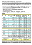
[SPECIFICATIONS]
FOR
I
CAR AND TRUCK
I
bonnurren;
Burst Current
Resistance
Suitable Car
1
;I;;
L ~ H
53H
I
1
OUH
190A
90A
380A
1 0.01 ohm 1
0.005 ohm
I
0 0015 ohm
0.0007 ohm
I
1/18. 1116 car
1/10 car
On-road: 25.5T
., ,
/ On-road: 212T I
On-road. b9T
I
L cells LIP
Off-road: 212T
Off-road: 28.5T
Off-road: 218T
cells NiMH
3650
size motor
2030 size motor
3650 size motor
Suitable
On-road: 28.5T
On-road: 218T
On-road: 212T
Brushless Motor
cells Lipo
Off-road: 213T
Off-road: 224T
Off-road: 218T
cells NiMH
3650 size motor
2030 size motor
3650 size motor
4-9 Cells NiMH or 2-3 Cells Li-Po
1) For 4-6 cells NiMH or 2 cells Lipo: You needn't change the fan combined with the ESC;
Battery
2) For 7-9 cell NiMH or 2 cells Lipo: You must change the fan combined with the controller
I because it cannot work with such a high voltage, so please choose a high voltage fan or supply
the fan from the receiver (+5V); ('NoGI)
6Vll A
6V11.5A
BEC Output
Motor Type
Sensorless Brushless Motor
31.5' 27.5' 16 1
31.5" 27.5' 24
Dimension
31.5' 24' 15 1
(The height of fan is not included)
I 19g (WlO wires) I 23g (WIO wires) I
309 (WIO wires)
1
329 (WIO wires)
Weight
-
L - .
Note?: For information about the hioh voltaoe coolino fan.
please refer to the brief introduction on page
3:
[BEGIN TO USE THE NEW ESCl
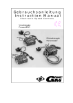
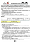
I.
Connect the ESC, motor, rdceiver, battery and servo
according to the following diagram
"+" and "-" wires of the ESC are connected with the battery
pack, and #A, #B and #C are connected with the motor wires.
The "SET" button is used for programming the ESC.
The control cable of the ESC (trio wires with black, red and
white color) is connected with the throttle channel of the
receiver (Usually CH2).
The #A, #B, #C wires of the ESC can be connected with the
motor wires freely (without any order). If the motor runs in the
opposite direction, please swap any two wire connections.
Note: You can use the transmitter t o set the throttle
channel t o the "Reverse" direction, and then the motor
will run oppositely. Please calibrate the throttle range
again after changing the direction of throttle channel.
Input TH channel
ICh 2)
Ark
"i
,,,,.
Sew0 plugged I to '
steering ch ( # I .
\
I
User Manual of "TURNIGY" Series Brushless Speed Controller
[TROUBLE SHOOTING]
In order to make the ESC fit the throttle range, you must calibrate it for the following cases; otherwise the ESC
cannot work properly.
1) Begin to use a new ESC;
2) Begin to use a new transmitter;
3) Change the settings of neutral position of the throttle ,stick,ATV or EPA parameters, etc.
There are 3 points need to be set, they are the top point of "forward"," backward" and the neutral point.
a~~
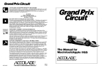
The following pictures show how to set the throttle range with a ~ u t a b transmitter.
A) Switch off the ESC, turn on the transmitter,
set the direction of throttle channel to "REV".
set the "EPAIATV" value of throttle channel to
"loo%", and disable the 'ABS" brake function
of your transmitter. (*Note2)
B) Hold the "SET" key and then switch on the
ESC, when the red LED begins to flash,
release the key immediately. ('Note3)
(Please refer to the picture on the right side)
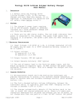
C) Set the THREE points
according to the steps
shown in the picture on
the right side.
1) Neutral point
2) End point of forward
direction
3) End point of backward
direction
D) When the process of
calibration is finished, the
motor can be started after
3 seconds.
end pmluon d bsdrwrd.
R e s 'SET he): the 5rwn
Pnrsa
LED Mashes o m andmaPor
LEQllea(las hriw and motor E D mmhm Uum andmffw
s&
'Beep. h n e
.MI-kuy. Um Green
emits .EmepBeepmtone
Pmas ' S E T ksy.
me Gman
emlb '8sspSesp.Esep'lone
Note2: Ifyou don't release the "SET" key after the red LED begins to flash, the ESC will enter the programmode, in
such a case, please switch off the ESC and re-calibrate the throttle range again from step A to step D.
Note3: The "SETnkey of TURNIGY-18A-SL is beside the main switch of the controller.
a) In normal use, if the throttle stick is in the neutral range, neither the red LED nor the green LED lights.
b) The red LED lights when the car is.run forward or backward and it will flash quickly when the car is braking.
c) The green LED lights when the throttle stick is moved to the top point of the forward zone.
[ALERT TONES1
1. lnput voltage abnormal alert tone: The ESC begins to check the input voltage when power on, if it is out of the
normal range, such an alert tone will be emitted: 'beep-beep-, beepbeep-, beep-beep-" (There is 1 second
time interval between every "beep-beep-" tone).
2. Throttle signal abnormal alert tone: When the ESC can't detect t e normal throttle signal, such an alert tone
will be emitted: "beep-, beep-, beep-" (There is 2 seconds time in rval between every "beep-" tone).
1
1
[PROTECTION FUNCTION]
!
1. Low voltage cut-off protection: If the voltage of a lithium battery pack is lower than the threshold for 2 seconds,
the ESC will cut of the output power. Please note that the ES cannot be restarted if the voltage of each
lithium cell is lower than 3.5V.
For NiMH battery packs, if the voltage of the whole NiMH battery ack is higher than 9.OV but lower than 12V,
it will be considered as a 3 cell lithium battery pack; If it is lowe than 9.OV, it will be considered as a 2 cell
lithium battery pack. For example, if the NiMH battery pack is 8.0 , and the threshold is set to 2.6VlCell. so it
will be considered as a 2 cell lithium battery pack, and the low-vo!tage cut-off threshold for this NiMH battery
pack is 2.6*2=5.2V.
2. Over-heat protection: When the temperature of the ESC is over a factory preset threshold for 5 seconds, the
ESC will cut off the output power. You can disable the over-heat kotection function for competition race.
3. Throttle signal loss protection: The ESC will cut off the output power if the throttle signal is lost for 0.2 second.
cl
i
11
Doc Ver. HK-13-V2-101119
Page
- 2-
battery pack and ESC are not Replace the connectors
correct
After power on, motor can't w rk, but Input voltage is abnormal, too Check the voltage of the battery
pack
emits "beep-beep-, beep-beep " alert high or too low.
tone. (Every "beep-beep-" has a time
interval of 1 second )
After power on, motor can't work, but Throttle signal is abnormal
Check the transmitter and the
receiver
emits "beep-, beep-, beep-" alert tone.
(Every "beep-" has a time interval of
Check the wire of the throttle
about 2 seconds)
channel
The motor runs in the opposite direction The wire connections between Swap any two wire connections
ESC and the motor need to be between the ESC and the motor.
changed
The motor suddenly stops running The throttle signal is lost
Check the transmitter and the
while in working state
receiver
Check the wire of the throttle
I channel
c
The ESC has entered the Low I ReDlace the batterv
- ~. a c k
Voltage Protection Mode
Random stop or restart or irregular Some connections are not Check all the connections: battery
working state
reliable
pack connections, throttle signal
wire, and motor connections, etc.
There is strong Electro - Reset the ESC to resume normal
Magnetic interference in flying operation. If the function could not
resume, you might need to move to
field.
another area to run the car.
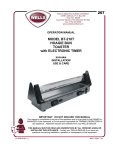
[OPTIONAL ACCESSORIES FbR UPGRADE1
We provide the following optional accessories for upgrade your power system:
Mark. Direction of the airflow
1. Cooling fan (12V): The high voltage fan is necessary when you are using
and the impeller
........
batterv oack more than 6 cells of NiMH. It is located on the heat sink of the ESC. it
helps cool the ESC with downward airtlow. The picture on the right side shows
the installation.
WARNING! Please note theioriginal fan (5V) combined with the ESC can
ONLY work with a 2 cells lithium battery pack or 4 6 cells NiMH battery pack.
Please NEVER use i t wlth a 3 cells lithium battery pack or NiMH battery pack
more than 6 cells, otherwise i t mag be destroyed.
Please check the label of the fan carefully t o confirm its working voltage
before using It.
sound is emitted
I
id
)
2.
1
1
Program card (Digital LED Display).
Program card is an optional accessory which needs to be purchased separately. It
has a friendly user interface. The process of programming the ESC becomes quite
easy and fast with this pocket sized device. When the programmable value needs
to be changed, please just plug the control wires of the ESC (trio wires with black,
red and white color) into the socket of the program card (The socket is on the right
corner, and marked with
), m u h e n connect the main battery pack to the
ESC, each item's value will be shown on the program card. Use "ITEM" and
VALUE" buttons to select the programmable items and new values, and then press
"OK" button to store the new settings into the ESC.
3. Advanced program box (LCD Display).
Advanced program box is an optional accessory which needs to be purchased separately.
It has LCD display to show the programmable items, so it can work as an individual device to set the ESC. And it
can also work as an USB adapter to connect the ESC with a PC to update the ESC firmware online.
User Manual of "TURNIGY' Series B~shleSs
Speed Controller
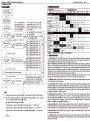
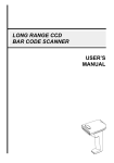
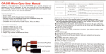
[PROGRAM THE ESCI
Doc Ver. HK-13-VZ-101119
1
+
ForwardIReverse
with Brake
Enter the corresponding
programmable item, the
RED LED flashesfor several
bmes, the times presents the
current value of this item
4
+
Red LED flashes
L
I
I
Hold the SET key,
Switch on the ESC
-
-3-
Proclrammable Value
Tum off the ESC,
Turn on the transmitter
I
Page
Green LED flashes
for 1 time
Enter the 1st item
'Runn~ngMode"
Release*
SET key
Press the SET key to choose the
programmable value , the RED LED
flashes for several times, the times
presents the serial number of the value
you are choosing
20%
SET key
Hold SET key for 3 seconds
Hold SET key for 3 seconds
I
I /--..-.The following steps are just like the above steps---
/
Hold SET key for 3 seconds
Green LED
for N times
,
5
*
33
5'
8
;
I1
Release) Enter the Nthitem
!Ml!'.I
i;
Press SET key to choose the value. the
flash times of RED LED means the serial
number of the value (1 time means the Ist
value, 2 times means the 2nd value...)
SET key
S?
I I i.I '
-5
*
-
K
B
m
*
In the program process, the motor will emit
tone at the same time when the LED is flashing.
f
If the "N" is bigger than the number " 5 , we e a long time flash and long "Beep---" tone to represent
"5,so it is easy to identify the items of the g number.
For example, if the LED flashes as the foll&ing:
"A long time flash + a short time flash" (Motor sounds "Beep---Beepn) = the No. 6 item
"A long time flash + 2 short time flash" (Motor sounds 'Beep--BeepBeep")
= the No. 7 item
= the No. 8 item
"A long time flash + 3 short time flash" (Motor sounds "Beep-BeepBeepBeep")
And so on.
100%
2.
Red LED flashes Itime, choose "0%"
Red LED flashes 2 times, choose "5%"
Ptess' Red LED flashes 3 times, choose " 10%"
SET key Red LED flashes 4 times, choose " 15%"
Red LED flashes 5 times, choose "20%"
Red LED flashes 6 times, choose "25%
Red LED flashes 7 times, choose ''30%"
Red LED flashes 6 times, choose "40%
flashes Itime, choose "None7'
flashes 2 times, choose "2.6V"
R d LED flashes 3 times, choose "2.8N"
I
SE;~&
I R& LED flashes 4 times, choose "3.OV"
d LED flashes 5 times, choose "3.2Vn
d LED flashes 6 times, choose " 3.4V"
for 3 times
80%
Press'
5-,
- 1
60%
-
"
Enter the 2nd item
"Drag Brake Force "
40%
Red LED flashes for 1 time to choose
"Forward with brake"
Red LED flashes for 2 times to choose )
-.n
SETkeY ForwardlReversewith brake"
Hold SET key lor 3 seconds
Greln LED flashes
for 2 times
.b c k
Crawler
Attention: The italics texts in the abov,djform are the default seitings.
&
3.1.Running Mode: With "Forward
Brake" mode, the car can go forward and brake, but cannot go backward,
this mode is suitable for competitioq; "ForwardlReverse with Brake" mode provides backward function, which is
suitable for training. The "Rock Crawler" mode is only used for rock crawler.
Note: "ForwardlReverse y f t h Brake" mode uses "Double-Click" method to make the car go backward.
When you move the thrott stick horn forward zone to backward zone for the first time, the ESC begins to brake
the motor, the motor spe s down but it is still running, not completely stopped, so the backward action is NOT
happened now. When the hrottle stick is moved to the backward zone again (The 2nd"click"), if the motor speed is
slowed down to zero (i.e. topped), the backward action will be occurred. The "Double-Click" method can prevent
mistakenly reverse when t e brake function is frequently used in steering.
With "Rock Crawler" mod , the reverse action will be happened immediately when the throttle stick is moved to
backward zone. Please se the "Drag Brake Force" to 100% if you choose the "Rock Crawler" mode.
1
3.2.Drag Brake Force: SQ the amount of drag brake applied at neutral throttle to simulate the slight braking effect
of a neutral brushed motor while coasting.
3.3.Low Voltage Cut-Off: The function is mainly to prevent the lithium battery pack from over discharging. When
using lithium battery pack, please s t the suitable value for low-voltage protection as you like. The ESC monitors
the battery's voltage at any time, if t(e voltage is lower than the threshold, the output power will be reduced to 50%
in 2 seconds. Please drive and stq the car at the side of the racing track as soon as possible, the ESC will
completely cut off the output powerR
i 10 seconds.
3.4.Stat-t Mode (Also called "~unch"): Select from "Levell (Soft)" to "Level 9 (Very aggressive)" start mode as
your like. Please note that if you @Hoose"Level 7" to "Level 9", you'd better use good quality battery pack with
powerful discharge abllity, otherwi& these modes cannot get the bursting start effect as you want. If the motor
cannot run smoothly (the motor igtrembling), it may caused by the weak discharge ability of the battery pack,
please choose a better battery or inqreasethe gear rate.
3.5.Maximum Brake Force: The;ESC provides proportional brake function. The brake force is related to the
position of the throttle stick. Maximum brake force refers to the force when the throttle stick is located at the top
point of the backward zone. Avery ldrge brake force can shorten the brake time, but it may damage the gears.
3.6.Maximum Revers? Force: Sets how much power will be applied in the reverse direction. Different value
makes different reverse speed.
3.7.lnitial Brake Force: It is also called "minimum brake force", and it refers to the force when the throttle stick is
located at the initial position of the backward zone. The default value is equal to the drag brake force, so the brake
effect can be very smooth.
User Manual of "TURNIGY" Series Brushless Speed Controller
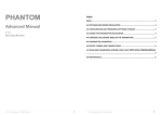
3.B.Throttle Neutral Range: Please see the following illustrations to adjuh the neutral range as your like.
Top point of
maximum brake
\
-\
Brake and backward zone
;
\
;
\
Forward
""
'
backward
zone
~BUbal
point
Nwbal zone
Top pdnt 01
\
Top point of maximumbrake
maximum lhmltle
3.9.Timing: There are many differences among structures and parameters of different brushless motors, so a fixed
timing ESC is difficult to compatible with all brushless motors. It is necessary to make the timing value
programmable. Please select the most suitable timing value according to the motor you are just using. Generally,
higher timing value brings out higher power output, but the whole efficiency of the system will be slightly lower
down.
3.10. Over-Heat Protection: If the function is activated, the output power will be cut-off when the temperature of
the ESC is up to a factory preset threshold for more than 5 seconds. When the protection happens, the Green LED
will flash.
I
At any time when the throttle is located in neutral zone (except in the throttle calibration or parameters program
pmcess), hold the 'SET" key for over 3 seconds, the red LED and green LED will flash at the same time , which
means each programmable item has be reset to its default value.
i,