1
Embedded Solutions
20AD67-00 E2 – 2012-09-25
AD67 – 6U I/O Extension for
A12, A15, D3, SC13
Configuration example
User Manual
®
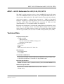
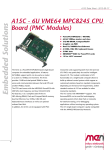
AD67 – 6U I/O Extension for A12, A15, D3, SC13
AD67 – 6U I/O Extension for A12, A15, D3, SC13
The AD67 is an I/O extension card for a variety of MEN CPU cards in 6U format
such as the VME SBC families A12 and A15, the CompactPCI SBC family D3 or
the stand-alone SBC family SC13. The AD67 is directly connected to the respective
single-board computer – without being connected to a VME or CompactPCI
backplane. Its purpose is to provide physical access to several onboard functions of
the above named SBCs. The AD67 provides connectors for USB, two PS/2
(keyboard/mouse), a 2.5" hard disk and three SA-Adapters™.
Especially the SA-Adapters™ allow flexible configuration with all kinds of legacy
serial I/O - also optically isolated - like RS232, RS422, RS485. The front panel
comes with two user LEDs and two switches for reset/abort. The AD67, together
with the respective SBC, takes two slots in a VME or CompactPCI system (8 HP).
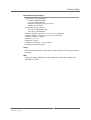
Technical Data
Peripheral Connections
• COM2 to COM4
- TTL signal level
- For easy connection of MEN SA-Adapters™
- Connectors at front panel
• PS/2 keyboard
• PS/2 mouse
• USB
• IDE connector for onboard 2.5" hard disk
Miscellaneous
• Reset/abort buttons
• 2 user LEDs
Connection to CPU Board
• Connection to COM2..4, PS/2, USB, buttons and LEDs via 40-pin ribbon cable
• Connection to onboard 2.5" hard disk via 44-pin ribbon cable
Electrical Specifications
• MTBF: 195 000 h @ 50°C (without hard disk) (derived from MIL-HDBK-217F)
Mechanical Specifications
• Dimensions: standard double Eurocard, 233.3 mm x 160 mm
• Weight: 204 g
MEN Mikro Elektronik GmbH
20AD67-00 E2 – 2012-09-25
2
Technical Data
Environmental Specifications
• Temperature range (operation):
- 0..+60°C without hard disk
- +5..+55°C with hard disk
- Industrial temperature range on request
- Airflow: min. 10 m³/h
• Temperature range (storage):
- -40..+85°C without hard disk
- -40..+65°C with hard disk
• Relative humidity (operation): max. 95% non-condensing
• Relative humidity (storage): max. 95% non-condensing
• Altitude: -300 m to +3000 m
• Shock: 15 g, 11 ms
• Bump: 10 g, 16 ms
• Vibration (sinusoidal): 2 g, 10..150 Hz
• Conformal coating on request
Safety
• PCB manufactured with a flammability rating of 94V-0 by UL recognized manufacturers
EMC
• Tested according to EN 55022 (radio disturbance), IEC1000-4-2 (ESD) and
IEC1000-4-4 (burst)
MEN Mikro Elektronik GmbH
20AD67-00 E2 – 2012-09-25
3
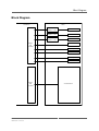
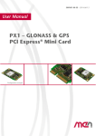
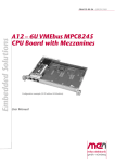
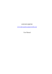
Block Diagram
Block Diagram
CPU Board
40‐pin
I/O Connector
AD67
SA Adapter
RS232...TTL
COM2
SA Adapter
RS232...TTL
COM3
SA Adapter
RS232...TTL
COM4
USB
PS/2 Keyboard
PS/2 Mouse
Abort/Reset
User LEDs
44‐pin
IDE Connector
MEN Mikro Elektronik GmbH
20AD67-00 E2 – 2012-09-25
2.5" Hard Disk
4
Product Safety
Product Safety
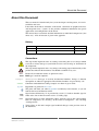
!
Electrostatic Discharge (ESD)
Computer boards and components contain electrostatic sensitive devices.
Electrostatic discharge (ESD) can damage components. To protect the board and
other components against damage from static electricity, you should follow some
precautions whenever you work on your computer.
• Power down and unplug your computer system when working on the inside.
• Hold components by the edges and try not to touch the IC chips, leads, or circuitry.
• Use a grounded wrist strap before handling computer components.
• Place components on a grounded antistatic pad or on the bag that came with the
component whenever the components are separated from the system.
• Store the board only in its original ESD-protected packaging. Retain the original
packaging in case you need to return the board to MEN for repair.
MEN Mikro Elektronik GmbH
20AD67-00 E2 – 2012-09-25
5
About this Document
About this Document
This user manual is intended only for system developers and integrators, it is not intended for end users.
It describes the hardware functions of the board, connection of peripheral devices
and integration into a system. It also provides additional information for special
applications and configurations of the board.
The manual does not include detailed information on individual components (data
sheets etc.). A list of literature is given in the appendix.
History
Issue
Comments
Date
E1
First edition
2003-05-09
E2
General update
2012-09-25
Conventions
This sign marks important notes or warnings concerning the use of voltages which
can lead to serious damage to your health and also cause damage or destruction of
the component.
!
italics
bold
monospace
This sign marks important notes or warnings concerning proper functionality of the
product described in this document. You should read them in any case.
Folder, file and function names are printed in italics.
Bold type is used for emphasis.
A monospaced font type is used for hexadecimal numbers, listings, C function
descriptions or wherever appropriate. Hexadecimal numbers are preceded by "0x".
comment
Comments embedded into coding examples are shown in green color.
hyperlink
Hyperlinks are printed in blue color.
The globe will show you where hyperlinks lead directly to the Internet, so you can
look for the latest information online.
IRQ#
/IRQ
Signal names followed by "#" or preceded by a slash ("/") indicate that this signal is
either active low or that it becomes active at a falling edge.
in/out
Signal directions in signal mnemonics tables generally refer to the corresponding
board or component, "in" meaning "to the board or component", "out" meaning
"coming from it".
Vertical lines on the outer margin signal technical changes to the previous issue of
the document.
MEN Mikro Elektronik GmbH
20AD67-00 E2 – 2012-09-25
6
About this Document
Legal Information
Changes
MEN Mikro Elektronik GmbH ("MEN") reserves the right to make changes without further notice to any products
herein.
Warranty, Guarantee, Liability
MEN makes no warranty, representation or guarantee of any kind regarding the suitability of its products for any
particular purpose, nor does MEN assume any liability arising out of the application or use of any product or
circuit, and specifically disclaims any and all liability, including, without limitation, consequential or incidental
damages. TO THE EXTENT APPLICABLE, SPECIFICALLY EXCLUDED ARE ANY IMPLIED
WARRANTIES ARISING BY OPERATION OF LAW, CUSTOM OR USAGE, INCLUDING WITHOUT
LIMITATION, THE IMPLIED WARRANTIES OF MERCHANTABILITY AND FITNESS FOR A
PARTICULAR PURPOSE OR USE. In no event shall MEN be liable for more than the contract price for the
products in question. If buyer does not notify MEN in writing within the foregoing warranty period, MEN shall
have no liability or obligation to buyer hereunder.
The publication is provided on the terms and understanding that:
1. MEN is not responsible for the results of any actions taken on the basis of information in the publication, nor
for any error in or omission from the publication; and
2. MEN is not engaged in rendering technical or other advice or services.
MEN expressly disclaims all and any liability and responsibility to any person, whether a reader of the publication
or not, in respect of anything, and of the consequences of anything, done or omitted to be done by any such person
in reliance, whether wholly or partially, on the whole or any part of the contents of the publication.
Conditions for Use, Field of Application
The correct function of MEN products in mission-critical and life-critical applications is limited to the
environmental specification given for each product in the technical user manual. The correct function of MEN
products under extended environmental conditions is limited to the individual requirement specification and
subsequent validation documents for each product for the applicable use case and has to be agreed upon in writing
by MEN and the customer. Should the customer purchase or use MEN products for any unintended or
unauthorized application, the customer shall indemnify and hold MEN and its officers, employees, subsidiaries,
affiliates, and distributors harmless against all claims, costs, damages, and expenses, and reasonable attorney fees
arising out of, directly or indirectly, any claim or personal injury or death associated with such unintended or
unauthorized use, even if such claim alleges that MEN was negligent regarding the design or manufacture of the
part. In no case is MEN liable for the correct function of the technical installation where MEN products are a part
of.
Trademarks
All products or services mentioned in this publication are identified by the trademarks, service marks, or product
names as designated by the companies which market those products. The trademarks and registered trademarks
are held by the companies producing them. Inquiries concerning such trademarks should be made directly to those
companies.
Conformity
MEN products are no ready-made products for end users. They are tested according to the standards given in the
Technical Data and thus enable you to achieve certification of the product according to the standards applicable in
your field of application.
MEN Mikro Elektronik GmbH
20AD67-00 E2 – 2012-09-25
7
About this Document
RoHS
Since July 1, 2006 all MEN standard products comply with RoHS legislation.
Since January 2005 the SMD and manual soldering processes at MEN have already been completely lead-free.
Between June 2004 and June 30, 2006 MEN’s selected component suppliers have changed delivery to RoHScompliant parts. During this period any change and status was traceable through the MEN ERP system and the
boards gradually became RoHS-compliant.
WEEE Application
The WEEE directive does not apply to fixed industrial plants and tools. The compliance is the responsibility of the
company which puts the product on the market, as defined in the directive; components and sub-assemblies are
not subject to product compliance.
In other words: Since MEN does not deliver ready-made products to end users, the WEEE directive is not
applicable for MEN. Users are nevertheless recommended to properly recycle all electronic boards which have
passed their life cycle.
Nevertheless, MEN is registered as a manufacturer in Germany. The registration number can be provided on
request.
Copyright © 2012 MEN Mikro Elektronik GmbH. All rights reserved.
Germany
MEN Mikro Elektronik GmbH
Neuwieder Straße 3-7
90411 Nuremberg
Phone +49-911-99 33 5-0
Fax +49-911-99 33 5-901
E-mail [email protected]
www.men.de
MEN Mikro Elektronik GmbH
20AD67-00 E2 – 2012-09-25
France
MEN Mikro Elektronik SA
18, rue René Cassin
ZA de la Châtelaine
74240 Gaillard
Phone +33 (0) 450-955-312
Fax +33 (0) 450-955-211
E-mail [email protected]
www.men-france.fr
USA
MEN Micro, Inc.
24 North Main Street
Ambler, PA 19002
Phone (215) 542-9575
Fax (215) 542-9577
E-mail [email protected]
www.menmicro.com
8
Contents
Contents
1 Getting Started . . . . . . . . . . . . . . . . . . . . . . . . . . . . . . . . . . . . . . . . . . . . . . . . 11
1.1 Map of the Board. . . . . . . . . . . . . . . . . . . . . . . . . . . . . . . . . . . . . . . . . 11
1.2 Connecting the Adapter to a CPU Board . . . . . . . . . . . . . . . . . . . . . . 12
2 Interface to the CPU Board . . . . . . . . . . . . . . . . . . . . . . . . . . . . . . . . . . . . . . 13
3 Interfaces to I/O Devices. . . . . . . . . . . . . . . . . . . . . . . . . . . . . . . . . . . . . . . . .
3.1 IDE Hard Disk Interface . . . . . . . . . . . . . . . . . . . . . . . . . . . . . . . . . . .
3.2 Serial Ports COM2..COM4 . . . . . . . . . . . . . . . . . . . . . . . . . . . . . . . . .
3.2.1
Installing SA-Adapters . . . . . . . . . . . . . . . . . . . . . . . . . . . . .
3.3 USB Interface . . . . . . . . . . . . . . . . . . . . . . . . . . . . . . . . . . . . . . . . . . .
3.3.1
Fuse Protection . . . . . . . . . . . . . . . . . . . . . . . . . . . . . . . . . . .
3.4 PS/2 Keyboard and Mouse Interfaces . . . . . . . . . . . . . . . . . . . . . . . . .
3.4.1
Fuse Protection . . . . . . . . . . . . . . . . . . . . . . . . . . . . . . . . . . .
3.5 Reset/Abort Buttons . . . . . . . . . . . . . . . . . . . . . . . . . . . . . . . . . . . . . .
3.6 User LEDs . . . . . . . . . . . . . . . . . . . . . . . . . . . . . . . . . . . . . . . . . . . . . .
15
15
18
19
20
20
21
22
23
23
4 Appendix . . . . . . . . . . . . . . . . . . . . . . . . . . . . . . . . . . . . . . . . . . . . . . . . . . . . .
4.1 Literature and Web Resources . . . . . . . . . . . . . . . . . . . . . . . . . . . . . . .
4.1.1
EIDE . . . . . . . . . . . . . . . . . . . . . . . . . . . . . . . . . . . . . . . . . . .
4.1.2
USB . . . . . . . . . . . . . . . . . . . . . . . . . . . . . . . . . . . . . . . . . . . .
4.2 Finding out the Product’s Article Number, Revision and Serial
Number . . . . . . . . . . . . . . . . . . . . . . . . . . . . . . . . . . . . . . . . . . . . . . . .
24
24
24
24
MEN Mikro Elektronik GmbH
20AD67-00 E2 – 2012-09-25
24
9
Figures
Figure 1.
Figure 2.
Figure 3.
Figure 4.
Map of the board – top view. . . . . . . . . . . . . . . . . . . . . . . . . . . . . . . . .
Position of fuse for USB protection on top side of PCB . . . . . . . . . . .
Position of fuse for keyboard/mouse protection on top side of PCB . .
Labels giving the product’s article number, revision and serial
number . . . . . . . . . . . . . . . . . . . . . . . . . . . . . . . . . . . . . . . . . . . . . . . . .
11
20
22
Pin assignment of the 40-pin I/O connector . . . . . . . . . . . . . . . . . . . . .
Signal mnemonics of 40-pin I/O connector . . . . . . . . . . . . . . . . . . . . .
Pin assignment of the 44-pin IDE connector . . . . . . . . . . . . . . . . . . . .
Signal mnemonics for 44-pin IDE connector . . . . . . . . . . . . . . . . . . . .
Pin assignment of the 10-pin COM2 serial port connector . . . . . . . . .
Pin assignment of the 10-pin COM3..COM4 serial port connectors . .
Signal mnemonics for 10-pin serial port connectors . . . . . . . . . . . . . .
Pin Assignment of USB Connector . . . . . . . . . . . . . . . . . . . . . . . . . . .
Signal Mnemonics of USB Connector . . . . . . . . . . . . . . . . . . . . . . . . .
Pin assignment of the 6-pin mini DIN keyboard connector . . . . . . . . .
Signal mnemonics for keyboard interface . . . . . . . . . . . . . . . . . . . . . .
Pin assignment of the 6-pin mini DIN mouse connector . . . . . . . . . . .
Signal mnemonics for mouse interface . . . . . . . . . . . . . . . . . . . . . . . .
13
14
16
17
18
18
18
20
20
21
21
21
21
24
Tables
Table 1.
Table 2.
Table 3.
Table 4.
Table 5.
Table 6.
Table 7.
Table 8.
Table 9.
Table 10.
Table 11.
Table 12.
Table 13.
MEN Mikro Elektronik GmbH
20AD67-00 E2 – 2012-09-25
10
Getting Started
1
Getting Started
This chapter will give an overview of the adapter card and hints on installation.
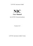
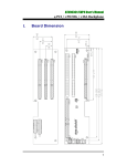
1.1
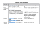
Map of the Board
Figure 1. Map of the board – top view
COM4
COM3
Board‐to‐board connector: I/O
COM2
Keyboard
2.5" Hard Disk
Mouse
USB
Reset/Abort Button
User LEDs
IDE Hard Disk Connector
Board‐to‐board connector: IDE
MEN Mikro Elektronik GmbH
20AD67-00 E2 – 2012-09-25
11
Getting Started
1.2
Connecting the Adapter to a CPU Board
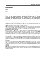
The AD67 I/O extension card was designed for use in standard 6U systems such as
CompactPCI or VMEbus. It can be connected via ribbon cable to MEN CPU boards
that feature a 40-pin I/O connector, e.g., MEN’s A12, A15 or D3 CPUs.
Do the following to install the AD67:
Make sure you have added any additional parts on the board that you may need,
e.g., SA-Adapters or hard disk.
Power-down your system.
Remove the CPU board to be extended by AD67 from the system.
Make sure the neighboring slot of your bus system to the right of the CPU
board is free.
Hold the AD67 over the CPU board and align the 40-pin ribbon cable included
with AD67 with the corresponding 40-pin connector of the CPU board.
Firmly connect the ribbon cable connector to the CPU board’s connector.
In the same fashion, you will have to connect the 44-pin IDE plug connectors
on AD67 and the CPU board via a ribbon cable, if you have installed a hard
disk on AD67. See also Chapter 3.1 IDE Hard Disk Interface on page 15.
Insert the two boards into two parallel slots of the bus system.
Lock the CPU board’s ejector handles.
Screw the AD67’s front-panel screws to the bus system slot.
MEN Mikro Elektronik GmbH
20AD67-00 E2 – 2012-09-25
12
Interface to the CPU Board
2
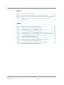
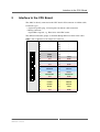
Interface to the CPU Board
The AD67 is directly connected to the CPU board’s I/O connector via ribbon cable.
Connector types:
• 40-pin low-profile plug, 2.54 mm pitch, for ribbon-cable connection
• Mating connector:
40-pin IDC receptacle, e.g. Elco Series 8290 IDC socket
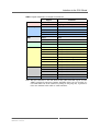
The different functional groups are marked through different colors in the tables.
Table 1. Pin assignment of the 40-pin I/O connector
40
2
MEN Mikro Elektronik GmbH
20AD67-00 E2 – 2012-09-25
39
1
40
-
39
-
38
-
37
-
36
-
35
-
34
-
33
-
32
RXD4
31
-
30
TXD4
29
-
28
RXD3
27
TXD3
26
+5V
25
GND
24
USBP0+
23
USBP0-
22
+5V
21
GND
20
MSDATA
19
MSCLK
18
KBDATA
17
KBCLK
16
LED2
15
LED1
14
ABRTBTN#
13
PWRBTN#
12
+5V
11
GND
10
RI2#
9
DCD2#
8
CTS2#
7
DSR2#
6
RTS2#
5
DTR2#
4
RXD2
3
TXD2
2
+5V
1
GND
13
Interface to the CPU Board
Table 2. Signal mnemonics of 40-pin I/O connector
Signal
Power
Mouse/Keyboard
LEDs
Button
COM2
COM3/COM4
USB
Function
+5V
+5V power supply
GND
Digital ground of respective interface
KBDATA
Keyboard data
KBCLK
Keyboard clock
MSDATA
Mouse data
MSCLK
Mouse clock
LED1
LED1
LED2
LED2
ABRTBTN#
Abort button
PWRBTN#
Reset button
CTS2#
Serial port COM2 clear to send
DCD2#
Serial port COM2 data carrier detect
DSR2#
Serial port COM2 data set ready
DTR2#
Serial port COM2 data terminal ready
RI2#
Serial port COM2 ring indicator
RTS2#
Serial port COM2 request to send
RXD2
Serial port COM2 receive data
TXD2
Serial port COM2 transmit data
RXD3
Serial port COM3 receive data
TXD3
Serial port COM3 transmit data
RXD4
Serial port COM4 receive data
TXD4
Serial port COM4 transmit data
USBP0+, USBP0-
USB port differential pair
Note: This I/O connector is the link between the CPU board I/O signals and the
AD67’s peripheral connectors, buttons and LEDs. Since you can view the signals from either side of the connector (coming in and going out), signal directions were omitted in this table to avoid confusion.
MEN Mikro Elektronik GmbH
20AD67-00 E2 – 2012-09-25
14
Interfaces to I/O Devices
3
Interfaces to I/O Devices
3.1
IDE Hard Disk Interface
The AD67 supports one IDE channel via a 44-pin connector. You can only connect a
master device. The card provides enough space for direct mounting of a 2.5" hard
disk. MEN offers a suitable hard disk together with any accessories needed for
mounting. For ordering options, please see MEN’s website.
!
The AD67 actually has two 44-pin IDE connectors. One is for connection of the
hard disk, the other for connection to the CPU board’s IDE connector. If you have
installed a hard disk, you also need to connect the latter to the CPU board via ribbon
cable. A suitable cable is included in MEN’s hard disk mounting kit. See also Figure
1, Map of the board – top view, on page 11 and Chapter 1.2 Connecting the Adapter
to a CPU Board on page 12.
The pinning of the IDE connectors complies with the ATA-4/ATAPI specification.
Connector types:
• 44-pin, 2-row receptacle, 2mm pitch
• Mating connector:
44-pin, 2-row plug, 2mm pitch
MEN Mikro Elektronik GmbH
20AD67-00 E2 – 2012-09-25
15
Interfaces to I/O Devices
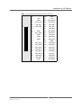
Table 3. Pin assignment of the 44-pin IDE connector
44
2
MEN Mikro Elektronik GmbH
20AD67-00 E2 – 2012-09-25
43
1
44
-
43
GND
42
+5V
41
+5V
40
GND
39
IDE_DASP#
38
IDE_CS3#
37
IDE_CS1#
36
IDE_A[2]
35
IDE_A[0]
34
IDE_ACT#
33
IDE_A[1]
32
-
31
IDE_IRQ
30
GND
29
IDE_DAK#
28
IDE_CSEL
27
IDE_RDY
26
GND
25
IDE_RD#
24
GND
23
IDE_WR#
22
GND
21
IDE_DRQ
20
-
19
GND
18
IDE_D[15]
17
IDE_D[0]
16
IDE_D[14]
15
IDE_D[1]
14
IDE_D[13]
13
IDE_D[2]
12
IDE_D[12]
11
IDE_D[3]
10
IDE_D[11]
9
IDE_D[4]
8
IDE_D[10]
7
IDE_D[5]
6
IDE_D[9]
5
IDE_D[6]
4
IDE_D[8]
3
IDE_D[7]
2
GND
1
IDE_RST#
16
Interfaces to I/O Devices
Table 4. Signal mnemonics for 44-pin IDE connector
Signal
Function
+5V
-
+5V power supply
GND
-
Digital ground
IDE_A[2:0]
out
IDE address [2:0]
IDE_ACT#
in
IDE active
IDE_DASP#
in/out
IDE device active or slave (device 1) present
IDE_CS1#
out
IDE chip select 1
IDE_CS3#
out
IDE chip select 3
IDE_CSEL
out
IDE cable select
IDE_D[15:0]
in/out
IDE data [15:0]
IDE_DAK#
out
IDE DMA acknowledge
IDE_DRQ
in
IDE DMA request
IDE_IRQ
in
IDE interrupt request
IDE_RD#
out
IDE read strobe
IDE_RDY
in
IDE ready
IDE_RST#
out
IDE reset
IDE_WR#
out
IDE write strobe
MEN Mikro Elektronik GmbH
20AD67-00 E2 – 2012-09-25
Direction
17
Interfaces to I/O Devices
3.2
Serial Ports COM2..COM4
For serial ports COM2 to COM4, three 10-pin connectors are provided that allow
direct mounting of MEN SA-Adapters. These adapters provide flexible interfacing,
from RS232 to TTY. All serial interfaces are available at the front panel.
Unlike COM3 and COM4, COM2 also supports handshake lines.
For different SA-Adapters available, see MEN’s website.
Connector types:
• 10-pin IDC receptacle, 2.54mm pitch, for ribbon-cable connection
• Mating connector:
10-pin low-profile plug
Table 5. Pin assignment of the 10-pin COM2 serial port connector
9
10
1
2
9
DCD#
10
RI#
7
DSR#
8
CTS#
5
DTR#
6
RTS#
3
TXD
4
RXD
1
GND
2
+5V
Table 6. Pin assignment of the 10-pin COM3..COM4 serial port connectors
9
10
1
2
9
-
10
-
7
-
8
-
5
-
6
-
3
TXD
4
RXD
1
GND
2
+5V
Table 7. Signal mnemonics for 10-pin serial port connectors
Signal
Function
+5V
-
+5V power supply
CTS#
in
Clear to send
DCD#
in
Data carrier detect
DSR#
in
Data set ready
DTR
out
Data terminal ready
GND
-
Digital ground
RI#
in
Ring indicator
RTS#
out
Request to send
RXD
in
Receive data
TXD
out
Transmit data
MEN Mikro Elektronik GmbH
20AD67-00 E2 – 2012-09-25
Direction
18
Interfaces to I/O Devices
3.2.1
Installing SA-Adapters
To mount an SA-Adapter, you must first remove the respective filler panel:
Loosen and remove the two cross-recess screws accessible at the front panel.
Remove the filler panel.
Now you can directly plug the SA-Adapter as described in the SA-Adapter user
manual. You can download the manuals from MEN’s website.
MEN Mikro Elektronik GmbH
20AD67-00 E2 – 2012-09-25
19
Interfaces to I/O Devices
3.3
USB Interface
The AD67 has a standard USB interface accessible at the front panel. The USB
version and data rates depend on the CPU board.
Connector types:
• 4-pin USB Series A receptacle according to Universal Serial Bus Specification
Revision 1.1
• Mating connector:
4-pin USB Series A plug according to Universal Serial Bus Specification Revision 1.1
Table 8. Pin Assignment of USB Connector
1
2
3
4
1
+5V
2
USBP-
3
USBP+
4
GND
Table 9. Signal Mnemonics of USB Connector
Signal
Function
+5V
-
+5V power supply, current-limited to 250 mA
by a polyswitch fuse
GND
-
Digital ground
USBP-, USBP+
in/out
USB port lines, differential pair
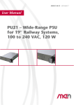
3.3.1
!
Direction
Fuse Protection
The power pin of the USB connector is protected by a fuse. This fuse is not
intended to be exchanged by the customer. Your warranty for the AD67 will
cease if you exchange the fuse on your own. Please send your board to MEN for
repair if a fuse blows.
•
•
•
•
Current rating: 250 mA
Type: PolySwitch RXE
Size: diameter 7.4 mm
MEN part number: 5002-0016
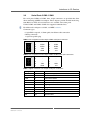
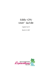
Figure 2. Position of fuse for USB protection on top side of PCB
Keyboard
2.5" Hard Disk
Mouse
USB
Fuse
Reset/Abort Button
User LEDs
MEN Mikro Elektronik GmbH
20AD67-00 E2 – 2012-09-25
20
Interfaces to I/O Devices
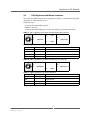
3.4
PS/2 Keyboard and Mouse Interfaces
Two 6-pin mini DIN connectors are provided to connect a standard PS/2 keyboard
and mouse or other pointing device.
Connector types:
• 6-pin circular mini DIN receptacle
• Mating connector:
6-pin circular mini DIN plug, available for soldering and crimp connection
Table 10. Pin assignment of the 6-pin mini DIN keyboard connector
4
4 6
2
1
+5V
2
-
6
-
1
KBDATA
5
KBCLOCK
3 5
3
GND
Table 11. Signal mnemonics for keyboard interface
Signal
Direction
Function
+5V
-
+5V supply, current-limited to 315 mA by a fuse
GND
-
Logic ground
KBCLOCK
out
Keyboard clock
KBDATA
in/out
Keyboard data
Table 12. Pin assignment of the 6-pin mini DIN mouse connector
4
4 6
2
1
+5V
2
-
6
-
1
MSEDATA
5
MSECLOCK
3 5
3
GND
Table 13. Signal mnemonics for mouse interface
Signal
Function
+5V
-
+5V supply, current-limited to 315 mA by a fuse
GND
-
Logic ground
MSECLOCK
out
Mouse clock
MSEDATA
in
Mouse data
MEN Mikro Elektronik GmbH
20AD67-00 E2 – 2012-09-25
Direction
21
Interfaces to I/O Devices
3.4.1
!
Fuse Protection
The power pins of the keyboard and mouse connectors are protected by a fuse. This
fuse is not intended to be exchanged by the customer. Your warranty for the
AD67 will cease if you exchange the fuse on your own. Please send your board to
MEN for repair if a fuse blows.
•
•
•
•
Current rating: 315 mA
Type: fast
Size: 5 x 20 mm
MEN part number: 5475-0021
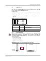
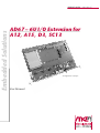
Figure 3. Position of fuse for keyboard/mouse protection on top side of PCB
COM2
Keyboard
Fuse
2.5" Hard Disk
Mouse
USB
MEN Mikro Elektronik GmbH
20AD67-00 E2 – 2012-09-25
22
Interfaces to I/O Devices
3.5
Reset/Abort Buttons
The AD67 provides standard reset and abort buttons at the front panel.
3.6
User LEDs
The AD67 provides two user LEDs at the front panel. Their function depends on the
CPU board and is configurable via software.
MEN Mikro Elektronik GmbH
20AD67-00 E2 – 2012-09-25
23
Appendix
4
Appendix
4.1
Literature and Web Resources
• AD67 data sheet with up-to-date information and documentation:
www.men.de/products/08AD67-.html
4.1.1
EIDE
• EIDE:
Information Technology - AT Attachment-3 Interface (ATA-3), Revision 6,
working draft; 1995; Accredited Standards Committee X3T10
4.1.2
USB
• USB Implementers Forum, Inc.
www.usb.org
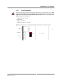
4.2
Finding out the Product’s Article Number, Revision and
Serial Number
MEN user documentation may describe several different models and/or design
revisions of the AD67. You can find information on the article number, the design
revision and the serial number on two labels attached to the board.
• Article number: Gives the product’s family and model. This is also MEN’s
ordering number. To be complete it must have 9 characters.
• Revision number: Gives the design revision of the product.
• Serial number: Unique identification assigned during production.
If you need support, you should communicate these numbers to MEN.
Figure 4. Labels giving the product’s article number, revision and serial number
Complete article number
08AD67-00
00.00.00
Revision number
MEN Mikro Elektronik GmbH
20AD67-00 E2 – 2012-09-25
Serial number
24