1
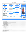
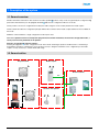
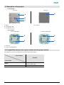
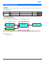
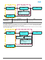
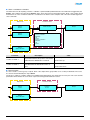
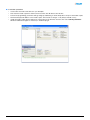
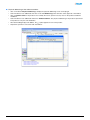
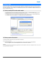
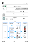
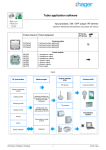
Tebis application software
Input products / Shutter Output / RF output
Electrical / Mechanical characteristics: see product user manual
TP device
RF devices
Product reference Product designation
Control module
WYJ42xQ
1-fold push button shutters / blinds RF
Power module
WUJ42
WUC18
1 shutter / blind output
Power supply
Inputs
RF push button
Media coupler
Output modules
KNX
Products KNX
RF devices
Loads connected
Gateway between the
RF products and the TP
products in a KNX
installation
Shutters and blinds
control
TP products
Configuration and
parameter setting of
radio products by ETS
Visualisation
system
Transmission of radio
controls
Status indication
WYJ42xQ
Diagnosis
1
6T 8012-02a
Shutter / blind output
Input modules
KNX
Output modules
KNX
Media coupler
Products KNX
Loads connected
Up / Down
Slat angle / Stop
Gateway between the
RF products and the TP
products in a KNX
installation
Wind alarm
Rain alarm
Configuration and
parameter setting of
radio products by ETS
Priority
Transmission of radio
controls
Scene
Diagnosis
Status indication
Visualisation
system
Summary
1. Description of the system.................................................................................................................................................. 3
1.1 General overview......................................................................................................................................................... 3
1.2 General outline ............................................................................................................................................................ 3
1.3 Description of the product............................................................................................................................................ 4
1.4 Compatibility between the control module and the power module .............................................................................. 4
1.5 Choice of application program in ETS ......................................................................................................................... 5
1.6 Function Description.................................................................................................................................................... 5
1.6.1 Inputs .................................................................................................................................................................... 5
1.6.2 Shutter / blind output ............................................................................................................................................. 5
1.7 Hardware and software required for configuration ...................................................................................................... 6
2. Configuration and settings ................................................................................................................................................ 7
2.1 Inputs........................................................................................................................................................................... 7
2.1.1 Objects List ........................................................................................................................................................... 7
2.1.2 Setting parameters................................................................................................................................................ 7
2.2 Shutter / blind output ................................................................................................................................................... 8
2.2.1 Objects List ........................................................................................................................................................... 8
2.2.2 Setting parameters................................................................................................................................................ 8
2.3 Configuration with media coupler (ETS version > 3.0f) ............................................................................................. 12
3. Factory reset ................................................................................................................................................................... 16
3.1 Factory reset by ETS via the media coupler.............................................................................................................. 16
3.2 Factory reset on the product...................................................................................................................................... 16
4. Example of application.................................................................................................................................................... 17
5. Main characteristics ........................................................................................................................................................ 18
WYJ42xQ
2
6T 8012-02a
1. Description of the system
1.1 General overview
All radio transmitters referred to in this document are radio quicklink products. They can be recognised by the configuration cfg
push button with which they are all equipped. Quicklink indicates the configuration without tools mode.
These products can also be configured in E mode by the USB configurer or in S mode by ETS via the media coupler.
This document describes the configuration principle with the ETS software via the media coupler and the functions available in
this mode.
Within the same installation, a single configuration mode may be used.
To re-use a product which has already been programmed in another installation, whatever the configuration mode, a
factory reset must be performed on the product.
Specifics for quicklink radio transmitters:
Pressing the cfg button acrivates configuration mode. In this mode, the dialogue product is bi-directional. For numbering or
programming operations, it will therefore no longer be necessary to bring the transmitters to be configured up to the media
coupler. It is only necessary to remain within radio range.
1.2 General outline
RF push button
Media coupler
Shutters / blinds
KNX
Shutters / blinds
Receiver / RF repeater
WYJ42xQ
3
6T 8012-02a
1.3 Description of the product
•
Control module
Front face
Rear face
D
A
B
C
A: Button
B: Configuration LED
C: Configuration button
•
D: Connector
Power module
Power supply 230V~
1 shutter / blind output
E
E
F
F
E: Connector
F: Connection terminal block
1.4 Compatibility between the control module and the power module
The table below shows the possible interconnections between the modules:
Control module
WYJ42xQ
Power module
WUJ42
1-fold push button shutters / blinds RF
1 shutter / blind output
WUC18
1-fold push button shutters / blinds RF
WYJ42xQ
4
6T 8012-02a
1.5 Choice of application program in ETS
Program selection is compulsory according to the type of combination used.
•
Right click on the product in the ETS tree structure, then select Change the application program…,
•
Select the product.
1.6 Function Description
1.6.1 Inputs
The push buttons are used to send shutter and blind controls.
The main functions are the following:
■ Emission of commands
• Shutters / Blinds control
• Up, Down, Stop, Slat angle
1.6.2 Shutter / blind output
The application software allows you to configure individually the outputs.
The main functions are the following:
■ Up / Down
The Up / Down Function allows moving up or down a shutter, a blind with inclinable slats, an awning, a Venetian blind, etc. This
function also allows opening and closing electric curtains. The command may come from switches, pushbuttons or automatic
controls.
■ Slat angle / Stop
The Slat angle / Stop function allows inclining the slats of a blind or stopping its current movement. This function allows modifying
the occultation or the direction of the light beams coming from outside. The control comes from push buttons: Press briefly the Up
/ Down push button.
■ Alarm 1 (Wind) and Alarm 2 (Rain)
The Alarm functions allow putting a shutter or a blind in a parametrisable predefined status. These functions have the highest
priority. No other command is taken into consideration if an Alarm is active. Only the end of the alarm enables again the other
commands.
■ Priority
The Priority function allows forcing a shutter or a blind into a predefined position. This command has priority, but at a lower level
than the alarms. No other command is taken into account if a priority is active. Only end of priority or alarm commands will be
taken into consideration.
WYJ42xQ
5
6T 8012-02a
■ Scene
The Scene function groups a set of outputs. These outputs can be set to an adjustable predefined status. Pressing a push button
activates a scene. Each output can be integrated in 8 different scenes.
■ Status indication
The 1 Bit status indication function is used to send the last movement of the shutter or blind.
1.7 Hardware and software required for configuration
•
•
•
Windows PC with the ETS software,
(Version 3.0f or higher or 4.0.7 or higher. Download and install the update if necessary.)
Media coupler. The software version must meet the following characteristics:
• Firmware: > 1.2.5
• Plug-in: > 1.0.11
(Check that you have administrator rights under Windows. If not you will not be able to install the media coupler plug-in.)
Programming interface.
WYJ42xQ
6
6T 8012-02a
2. Configuration and settings
2.1 Inputs
2.1.1 Objects List
Parameters
Shutters /
blinds
N°
Name
Function of the object
Length
C
R
W T
0
Input
Up / Down
1 bit
C
R
-
T
1
Input
Slat angle / Stop
1 bit
C
R
-
T
2.1.2 Setting parameters
■ Channel function: Shutters / blinds
This function controls shutters and blinds (Up, Down and slat angle adjustment for blinds).
Object ETS
Object
Slat angle / Stop
Parameters ETS
Channel function
Shutters / blinds
Output
Object
Up / Down
This function is used to control a shutter or blind using two push buttons (Inputs). One button for Up and one button for down.
The function transmit the Up / Down object (long key press) and the Slat angle adjustment / Stop object (short key press).
Remark:
• short key-press: < 0.4 s
• long key-press: >= 0.4 s
WYJ42xQ
7
6T 8012-02a
2.2 Shutter / blind output
2.2.1 Objects List
N°
Name
Function of the object
Length
C
R
W
T
2
Output
Up / Down
1 bit
C
R
W
-
3
Output
Slat angle / Stop
1 bit
C
R
W
-
4
Output
Priority
2 bit
C
R
W
-
5
Output
Alarm 1
1 bit
C
R
W
-
6
Output
Alarm 2
1 bit
C
R
W
-
7
Output
Scene
1 byte
C
R
W
-
8
Output
Status indication
1 bit
C
R
-
T
2.2.2 Setting parameters
■ Up / Down and status indication
The Up / Down Function allows moving up or down a shutter, a blind with inclinable slats, an awning, a Venetian blind, etc.
This function also allows opening and closing electric curtains. The command may come from switches, pushbuttons or automatic
controls.
Description of the 1 Bit status indiction object:
0: last up movement,
1: last down movement.
WYJ42xQ
8
6T 8012-02a
Object ETS
Parameters ETS
Object
Up / Down
Function
Up / Down
Output
Parameter:
Complete Down movement duration:
- Duration
Object
Status indication
Parameter
Complete Down
movement duration
Description
Value
This parameter defines the contact closing time
for a complete down movement.
From 0 to 500 s in intervals of 1 s
Default value: 120 s
■ Slat angle / Stop function
The Slat angle / Stop function allows inclining the slats of a blind or stopping its current movement. This function allows modifying
the occultation or the direction of the light beams coming from outside. This function is started by the Slat angle / Stop object.
The desired slant angle is obtained by a succession of control pulses.
The settings consist of programming the length of a press command that defines the number of presses to move from a slat angle
of 0% to a slat angle of 100%.
Object ETS
Parameters ETS
Object
Slat angle
Channel function
Slat angle / Stop
Type of function
Type of function
- Shutter
- Blind
Output
Parameter:
Relay closing time for slat positioning
Value (1 ... 50 x 50 ms)
- Value (1 ... 50 x 50 ms)
Object
Status indication
WYJ42xQ
9
6T 8012-02a
■ Alarm 1 and Alarm 2 functions
The Alarm functions allow putting a shutter or a blind in a parametrisable predefined status. The wind alarm is triggered by the
Alarm 1 object and the rain alarm by the Alarm 2 object. These functions have the highest priority. Alarm 1 has a higher priority
than Alarm 2. No other command is taken into consideration if an Alarm is active. Only the end of the alarm enables again the
other commands.
Object ETS
Parameters ETS
Object
Alarm 1
Alarm function
Object
Alarm 2
Output
Position on alarm 1:
- Maintain
- Up
- Down
Position on alarm 2:
- Maintain
- Up
- Down
Object
Status indication
Parameter
Description
Position on alarm 1
Position on alarm 2
Value
This parameter defines the position of the shutter
or blind when the Wind alarm is activated.
Maintain, Up, Down
Default value: Up
This parameter defines the position of the shutter Maintain, Up, Down
or the blind when the Rain alarm function is
active.
Default value: Down
■ Scene function
A scene is used to control a group of outputs. Each of the outputs in the group will be set to a status pre-defined for the scene.
A scene has been initiated by the object Scene.
The group of outputs is created in advance by establishing the link between the outputs that are to be part of the scene and the
push button which initiates the scene. Each output can be integrated in 8 different scenes.
Object ETS
Parameters ETS
Object
Scene
Function
Scene
Output
Object
Status indication
WYJ42xQ
10
6T 8012-02a
➜ Description of the Scene object (1 byte)
7
6
Learn
x
5
4
3
2
1
0
Scene number
Learning and storing in the room
This procedure modifies and stores a scene by local action on the push buttons located in the room:
• Activate the scene by pressing briefly on the room push button that triggers the scene,
• Set the outputs to the desired status using the push buttons that control them individually,
• Store the output statuses by pressing the room push button that triggers the scene for longer than 5 s.
Storage is indicated by the inversion of the status of the outputs concerned for 3s.
WYJ42xQ
11
6T 8012-02a
2.3 Configuration with media coupler (ETS version > 3.0f)
■ Configuration principle
The TR131 media coupler enables confuguration by ETS of RF devices for a KNX radio installation or a mixed KNX installation
including RF devices and wired buses. For normal operation, the radio transmitters operate in a one-direction mode.
Configuration takes place in bi-directional mode.
■ Implementation recommendations
1. The Media coupler must remain in place after configuration. It sends the commands between the radio products and the
wired products in auto mode.
2. The coupler must be at the head of the line: x.y.0 type physical address.
3. The coupler must be in a different line than the USB / series / IP interface.
4. Use of old generation media couplers (TR130A / B) is not authorised in an installation containing a new media coupler
(TR131A / B).
5. Separate the radio and TP lines:
• The radio line must not contain TP products: the views of the line in ETS and in the plug-in would contain
inconsistencies.
• The TP lines must not contain radio products: it would be impossible to configure these radio products.
6. Only use the plug-in to program the physical addresses and download the products. As ETS cannot program radio
products, it is not possible to use the usual configuration menus.
7. The product copy function must not be used in ETS for radio products. It causes inconsistencies in the projects leading to
plug-in malfunctions.
8. Copying projects which already contain a configured media coupler leads to plug-in malfunctions.
9. The use of the "default" button in the ETS parameter setting window is not recommended. This results in:
➜ The loss of the parameters of a product which has already been configured.
➜ Desynchronisation between the plug-in data and the radio products which have already been configured.
10. During the physical addressing, the download or the factory reset procedures of unidirectional radio products, several
attempts may be needed for a successful completion of the procedure.
11. Changing the line of a media coupler which is already configured leads to plug-in malfunctions.
12. Do not use ETS Software function Unload / Unload application.
WYJ42xQ
12
6T 8012-02a
■ Installation procedure
• Create a line reserved for RF devices in your ETS plan,
• First insert the media coupler into this line, then insert the other RF devices into this line,
• Perform the programming, parameter settings and group addressing for all the RF products except for the media coupler,
• Download the physical address of the media coupler. This must be of the type 1.1.0. (always end with a zero),
• Install the media coupler plug-in: Right-click on the product in the ETS tree structure, then select edit the parameters.
Windows Administrator rights are necessary to install the plug in.
WYJ42xQ
13
6T 8012-02a
■ Physical addressing of the radio transmitters
• Click on the button Physical addressing to display the physical addressing screen for the plug in,
• Select the device to be addressed, then click on the field Addressing in the menu line at the upper left of the window,
• Click on Product search, if the product is not found by the search, perform a factory reset on the product outside the
installation,
• Select the device to be addressed and click on Attribute address. The physical addressing of the product is performed.
The product is now part of the installation,
• After downloading the physical address, the
symbol appears in front of the product,
• Repeat this operation for the other radio transmitters.
WYJ42xQ
14
6T 8012-02a
■ Downloading the program and the parameters
This operation is performed using the plug-in. There are 2 ways of accessing the Download view:
•
From the media coupler
• Right-click on the product in the ETS tree structure, then select edit the parameters,
• Click on Download and follow the instructions on the screen.
•
From the RF product to be downloaded
• Right click on the product in the ETS tree structure, then select Download RF product… and follow the instructions
on the screen.
The right-hand window allows you to select the parameters and / or links to be downloaded for each product.
Finalise the download by selecting the type of download in the upper bar:
• Selected to download the selected parameters and links,
• All parameters to download all the parameters of all the products displayed,
• All links to download all the links for all the products displayed,
• All to download all the parameters and all the links of all the products displayed.
To test the functions and the KNX radio communication, return to normal use mode and wait 15 s before pressing a control button
on a transmitter.
Caution: The media coupler plug-in must be deactivated during the functional tests.
NB: For more information, refer to the description for the TR131 application software.
WYJ42xQ
15
6T 8012-02a
3. Factory reset
This function enables the device to be returned to its initial configuration (configuration when it came out of the factory). After a
device reset, the device can be re-used in a new installation. A factory reset can be performed either directly on the product or by
the media coupler plug-in. This last solution is recommended if the product is part of an installation configured by ETS, thus the
device is erased from the project.
3.1 Factory reset by ETS via the media coupler
•
•
For a product which is part of the installation (known by the media coupler): In the Physical addressing menu, select
Factory reset and then follow the instructions which appear on the screen,
For a product which is not part of the installation (unknown by the media coupler): In the menu Physical addressing,
select RESET device out of installation, then Unidirectional device with Addr. button.
3.2 Factory reset on the product
It is always possible to perform the factory reset directly on the device.
Factory reset on the product:
• Do a long key press (> 10 seconds) on the cfg push button, release the button when the cfg LED blinks,
• Wait for the cfg LED to switch off, indicating that the factory reset has been completed.
Remark:
To re-use a product which has already been programmed in another installation, whatever the configuration mode, a factory reset
must be performed on the product.
WYJ42xQ
16
6T 8012-02a
4. Example of application
Module WYJ42xQ controls module WUJ42 and the 4 shutter outputs module.
Operation:
• Press on the push button 1: Shutter up,
• Press on the push button 2: Shutter Down.
Equipment:
1x WYJ42xQ
1x WUJ42
1 4 shutter outputs module
Object KNX
WYJ42xQ
WUJ42
N°
N°
Object name
Object name
0
Input - Up / Down
➜
2
Output - Up / Down
1
Input - Slat angle / Stop
➜
3
Output - Slat angle / Stop
WYJ42xQ
4 shutter outputs module
Object name
Object name
N°
0
Input - Up / Down
➜
Output - Up / Down
1
Input - Slat angle / Stop
➜
Output - Slat angle / Stop
Parameters KNX
WUJ42
WYJ42xQ
4 shutter outputs module
Output
Channel function
Blind
Complete Down movement
duration
50
Default settings
Default settings
Comment:
• A short press on push button 1 or 2 stops the shutter or tilts the slats of the blind,
• A long press on push button 1 raises the shutters,
• A long press on push button 2 lowers the shutters.
WYJ42xQ
17
6T 8012-02a
5. Main characteristics
Product
WYJ42xQ
Max. number of group addresses
80
Max. number of links
90
WYJ42xQ
18
6T 8012-02a
WYJ42xQ
19
6T 8012-02a