1
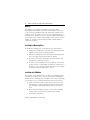
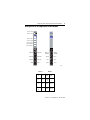
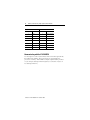
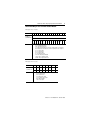
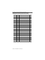
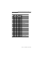
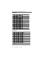
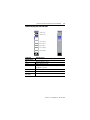
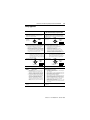
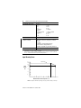
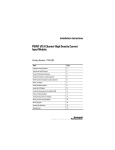
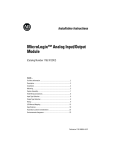
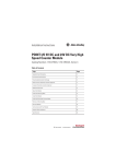
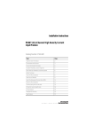
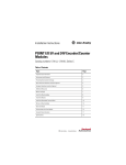
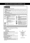
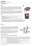
Installation Instructions
POINT I/O 24V dc Very High Speed
Counter Module
(Cat. No. 1734-VHSC24)
ule
od tus
MS
ta
ork
tw s
NeStatuE:
9
:
DE
11
NO
D
NO
4
C ED
V D PE R
24 H S NTE
HIGCOU
0
0
1
1
5
3
6
2
8
7
10
1
41825
Description
Description
7
1
Mounting Base1
2
Mechanical Keying (orange)
8
DIN Rail Locking Screw (orange)
3
Module Wiring Diagram
9
Slide-in Writable Label
4
Module Locking Mechanism
10
Interlocking Side Pieces
5
Insertable I/O Module 1
11
Insertable I/O Module 2
6
RTB Removal Handle
1
Removable Terminal Block (RTB)1
Wiring Base Assembly consists of item 1) mounting base, 1734-MB and item 7) removable
terminal block, 1734-RT❒❒.
POINT I/O is a trademark of Rockwell Automation1
DeviceNet is a trademark of ODVA, Inc.
Publication 1734-IN003B-EN-P - October 2000
2
POINT I/O 24V dc Very High Speed Counter Module
General
The VHSC is a two-module set. Module 1 houses the VHSC
functionality while module 2 provides screw terminals necessary to
access chassis ground (Chas Gnd) and common (C). Module 2 also
connects screw 4 to 5 and screw 6 to 7 for ease of wiring power to
the input device. Module 2 is not necessary for VHSC functionality; it
serves only to ease customer wiring. Module 2 does not use a node
address, or consume power from the PointBus. Mount module 2
adjacent to module 1.
Installing the Mounting Base
To install the mounting base on the DIN rail, proceed as follows.
1. Position the mounting base vertically above the installed units
(adapter, power supply or existing module).
2. Slide the mounting base down allowing the interlocking side
pieces to engage the adjacent module or adapter.
3. Press firmly to seat the mounting base on the DIN rail. The
mounting base will snap into place.
4. To remove the mounting base from the DIN rail, remove the
module, and use a small bladed screwdriver to rotate the base
locking screw to a vertical position. This releases the locking
mechanism. Then lift straight up to remove.
Installing the I/O Module
The module can be installed before, or after base installation. Make
sure that the mounting base is correctly keyed before installing the
module into the mounting base. In addition, make sure the mounting
base locking screw is positioned horizontal referenced to the base.
1. Using a bladed screwdriver, rotate the keyswitch (2) on the
mounting base clockwise until the number required for the
type of module being installed aligns with the notch in the
base.
2. Make certain the DIN rail locking screw is in the horizontal
position. (You cannot insert the module if the locking
mechanism is unlocked.)
Publication 1734-IN003B-EN-P - October 2000
POINT I/O 24V dc Very High Speed Counter Module
3
3. Insert the module straight down into the mounting base and
press to secure. The module will lock into place.
Installing the Removable Terminal Block (RTB)
A removable terminal block is supplied with your wiring base
assembly. To remove, pull up on the RTB handle. This allows the
mounting base to be removed and replaced as necessary without
removing any of the wiring. To reinsert the removable terminal block,
proceed as follows.
1. Insert the end opposite the handle into the base unit. This end
has a curved section that engages with the wiring base.
2. Rotate the terminal block into the wiring base until it locks
itself in place.
3. If an I/O module is installed, snap the RTB handle into place
on the module.
Removing a Mounting Base
To remove a mounting base, you must remove any installed module
in the base, and the module installed to the right of the base to be
removed. Remove the removable terminal block (if wired).
1. Unlatch the RTB handle on the I/O module.
2. Pull on the RTB handle to remove the removable terminal
block.
3. Press on the module lock on the top of the module.
4. Pull on the I/O module to remove from the base.
5. Use a small bladed screwdriver to rotate the orange base
locking screw to a vertical position. This releases the locking
mechanism.
6. Then lift straight up to remove.
Publication 1734-IN003B-EN-P - October 2000
4
POINT I/O 24V dc Very High Speed Counter Module
European Communities (EC) Directive Compliance
If this product has the CE mark it is approved for installation within
the European Union and EEA regions. It has been designed and
tested to meet the following directives.
EMC Directive
This product is tested to meet the Council Directive 89/336/EC
Electromagnetic Compatibility (EMC) by applying the following
standards, in whole or in part, documented in a technical
construction file:
• EN 50081-2 EMC — Generic Emission Standard, Part 2 —
Industrial Environment
• EN 50082-2 EMC — Generic Immunity Standard, Part 2 —
Industrial Environment
This product is intended for use in an industrial environment.
Low Voltage Directive
This product is tested to meet Council Directive 73/23/EEC Low
Voltage, by applying the safety requirements of EN 61131-2
Programmable Controllers, Part 2 - Equipment Requirements and
Tests. For specific information required by EN 61131-2, see the
appropriate sections in this publication, as well as publication
1770-4.1, Allen-Bradley Industrial Automation Wiring and Grounding
Guidelines.
Open style devices must be provided with environmental and safety
protection by proper mounting in enclosures designed for specific
application conditions. See NEMA Standards publication 250 and IEC
publication 529, as applicable, for explanations of the degrees of
protection provided by different types of enclosures.
Publication 1734-IN003B-EN-P - October 2000
POINT I/O 24V dc Very High Speed Counter Module
5
Wiring the 24V dc Very High Speed Counter Module
Module Status
Network Status
Status of Input A
Status of Input B
Status of Input Z
0
0
1
1
Status of Output 0
Status of Output 1
Input A
Input Aret
Chassis
Ground
Input B
Input Bret
RET 0
RET 1
Input Z
Input Zret
-Vaux
-Vaux
Out 1
+Vaux
+Vaux
Out 0
Chassis
Ground
42016
Module 1
1
0
3
B
4
2
Bret
5
Z
6
0
Aret
A
2
Out
0
Module 2
RET
0
4
Zret
7
Chas
Gnd
Out
1
-Vaux
1
Chas
Gnd
3
RET
1
5
-Vaux
6
7
+Vaux
+Vaux
Publication 1734-IN003B-EN-P - October 2000
6
POINT I/O 24V dc Very High Speed Counter Module
Module 1 Terminations
Module 2 Terminations
0
A
0
Chassis Ground
1
Aret
1
Chassis Ground
2
B
2
Out 0 RET
3
Bret
3
Out 1 RET
4
Z
4
Vaux -
5
Zret
5
Vaux -
6
Out 0
6
Vaux +
7
Out 1
7
Vaux +
Communicating with the 1734-VHSC24
I/O messages are sent to (consumed) and received from (produced)
the POINT I/O modules. These messages are mapped into the
processor’s memory. This POINT I/O input/output module produces
6 bytes of input data ((scanner Rx) (status). It consumes 2 bytes of
I/O data ((scanner Tx).
Publication 1734-IN003B-EN-P - October 2000
POINT I/O 24V dc Very High Speed Counter Module
7
Default Data Map for the 1734-VHSC Counter Module
Message size: 6 Bytes
15
14
13
Produces
(scanner Rx)
12
11
10
09
08
07
06
05
04
03
02
01
00
C
0
Z
D
0
Channel 0 value of present counter state (LSW)
Channel 0 value of present counter state (MSW)
E
F
P
E
N
R
0
F
S
F
S
O
S
O
S
0
Z
S
B
S
A
S
C
1
Where:PE = Programming error
EF = EEPROM fault status
NR = Not ready status bit
FS = Output fault status bit - bit 10 for output 0, bit 11 for output 1
OS = Output on/off status bit - bit 8 for output 0, bit 9 for output 1
ZS = Z input status
BS = B input status
AS = A input status
C = Stored data count
ZD = Zero frequency detected
LSW = Least significant word
MSW = Most significant word
Message size: 2 bytes
07
Consumes
(scanner Tx)
06
05
04
03
02
01
00
0
0
0
0
0
VR
CP
CR
DS
ES
OE
FO
DS
ES
OE
FO
Where:VR = Value reset of stored/accumulated count
CP = Counter preset
CR = Counter reset
DS = Diagnostic speed
ES = Electronic fuse select
OE = Output enable
FO = Force output
Publication 1734-IN003B-EN-P - October 2000
8
POINT I/O 24V dc Very High Speed Counter Module
Configuring Your Very High Speed Counter Module
Parameter
Set/Get
Description
Bytes
1
Set/Get
Counter Configuration (see page 9)
1
2
Set/Get
Filter Selection (see page 10)
1
3
Set/Get
Decimal Position
1
4
Set/Get
Active Output Assembly
1
5
Set/Get
Time Base Value/PWM Period
2
6
Set/Get
Gate Interval
1
7
Set/Get
Channel Scalar (see page 10)
1
8
Set/Get
Output 0 Ties
1
9
Set/Get
Output 1 Ties
1
10
Set/Get
Channel Rollover Value
4
11
Set/Get
Channel Preset Value
4
12
Set/Get
ON Value 1
4
13
Set/Get
OFF Value 1
4
14
Set/Get
ON Value 2
4
15
Set/Get
OFF Value 2
4
16
Set/Get
ON Value 3
4
17
Set/Get
OFF Value 3
4
18
Set/Get
ON Value 4
4
19
Set/Get
OFF Value 4
4
20
Set/Get
PWM Safe State Value
2
21
Set/Get
Counter Control Safe State
1
22
Set/Get
Output Control Safe State
1
Publication 1734-IN003B-EN-P - October 2000
POINT I/O 24V dc Very High Speed Counter Module
9
Counter Configuration
07
06
ZI
05
04
03
02
01
00
0
0
0
0
Counter
0
0
0
1
Encoder X1
0
0
1
0
Encoder X2
0
0
1
1
PWM
0
1
0
0
Encoder X4
0
1
0
1
Period/Rate
0
1
1
0
Continuous/Rate
0
1
1
1
Rate Measurement
MD
CF
Counter 0
0
0
0
Store Count Disabled
0
0
1
Mode 1 - store/continue
0
1
0
Mode 2 - store/wait/resume
0
1
1
Mode 3 - store, reset/wait/start
1
0
0
Mode 4 - store, reset/start
1
0
1
Reserved
1
1
0
Reserved
1
1
1
Reserved
0
Z input - 0 = not inverted
1
Z input - 1 = inverted
Publication 1734-IN003B-EN-P - October 2000
10
POINT I/O 24V dc Very High Speed Counter Module
Filter Selection
07
06
05
04
0
ZF
BF
AF
03
02
01
00
0
0
0
0
No Filter
0
0
0
1
50kHz (10µs + 0µs/-1.6µs)
0
0
1
0
5kHz (100µs + 0µs/-13.2µs)
0
1
0
0
500Hz (1.0ms + 0ms/-125µs)
1
0
0
0
50Hz (10ms + 0ms/-1.25ms)
FS
0
A input not filtered
1
A input filtered
0
B input not filtered
1
B input filtered
0
Z input not filtered
1
Z input filtered
Scalar Selection
07
06
05
04
03
02
01
00
Scalar1
0
0
0
0
0
0
0
1
Z - Fmin = 0.149Hz
0
0
0
0
0
0
1
0
Z/2 - Fmin = 0.298Hz
0
0
0
0
0
1
0
0
Z/4 - Fmin = 0.596Hz
0
0
0
0
1
0
0
0
Z/8 - Fmin = 1.192Hz
0
0
0
1
0
0
0
0
Z/16 - Fmin = 2.384Hz
0
0
1
0
0
0
0
0
Z/32 - Fmin = 4.768Hz
0
1
0
0
0
0
0
0
Z/64 - Fmin = 9.537Hz
1
0
0
0
0
0
0
0
Z/128 - Fmin = 19.073Hz
1 Where Fmin indicates the frequency at which the zero frequency detect is asserted due to
counter overflow.
Publication 1734-IN003B-EN-P - October 2000
POINT I/O 24V dc Very High Speed Counter Module
11
Assemblies
The Very High Speed Counter Module uses several words to
communicate real time input and output data as well as non-real time
module information (i.e. description, revision, etc) and configuration.
The following table shows the words which can be exchanged.
Data may be read (get) or written (set) using an Explicit Message.
Instances
Services
Field
Bytes
Get
Present Channel Data
4
Status
2
Stored Channel Data
4
Status
2
Present Channel Data
4
Stored Channel Data
4
Status
2
(Dec/Hex)
#101 (0x65)
#102 (0x66)
#103 (0x67)
Get
Get
#104 (0x68)
Get
Programming Error Code
2
#105 (0x69)
Set/Get
Counter Control
1
Output Control
1
#106 (0x6a)
Set/Get
PWM Value
2
#107 (0x6b)
Set/Get
PWM Value
2
Counter Control
1
Output Control
1
Counter Configuration
1
Filter Selection
1
Decimal Position
1
Active Output Assembly
1
Time Base or PWM Period
2
Gate Interval
1
Scalar
1
#108 (0x6c)
Set/Get
Publication 1734-IN003B-EN-P - October 2000
12
POINT I/O 24V dc Very High Speed Counter Module
Output 0 Ties
1
Output 1 Ties
1
Rollover Value
4
Preset Value
4
ON Value # 1
4
OFF Value #1
4
ON Value # 2
4
OFF Value #2
4
ON Value # 3
4
OFF Value #3
4
ON Value # 4
4
OFF Value #4
4
PWM Safe State Value
2
Counter Control SSV
1
Output Control SSV
1
Publication 1734-IN003B-EN-P - October 2000
POINT I/O 24V dc Very High Speed Counter Module
13
Troubleshooting with the Indicators
Module Status
Network Status
Status of Input A
0
Status of Input B
1
Status of Input Z
0
1
Status of Output 0
Status of Output 1
Indication
Module Status
Off
Green
Flashing Green
Flashing Red
Red
Flashing
Red/Green
Probable Cause
No power applied to device
Device operating normally
Device needs commissioning due to configuration missing,
incomplete or incorrect.
Recoverable fault.
Unrecoverable fault may require device replacement
Device is in self-test
Publication 1734-IN003B-EN-P - October 2000
14
POINT I/O 24V dc Very High Speed Counter Module
Indication
Network Status
Off
Flashing Green
Green
Flashing Red
Red
Flashing
Red/Green
Indication
Input Status
Off
Yellow
Flashing Yellow
Indication
Output Status
Off
Yellow
Flashing Yellow
Flashing Red
Flashing
Red/Yellow
Probable Cause
Device is not on-line
- Device has not completed dup_MAC_id test.
- Device not powered - check module status indicator
Device is on-line but has no connections in the established
state.
Device on-line and has connections in the established state.
One or more I/O connections in timed-out state
Critical link failure - failed communication device. Device
detected error that prevents it communicating on the
network.
Communication faulted device - the device has detected a
network access error and is in communication faulted state.
Device has received and accepted an Identify
Communication Faulted Request - long protocol message.
Probable Cause
Input inactive
Input is active and under control
Input is toggling on and off
Probable Cause
Output inactive
Output is active and under control
Output is toggling
Output is faulted (open, short or no output power)
Output is toggling and faulted (possibly open)
Publication 1734-IN003B-EN-P - October 2000
POINT I/O 24V dc Very High Speed Counter Module
15
Safety Approvals
C-UL and UL Hazardous Location Approval
Approbation d’utilisation dans des
environnements dangereux par la C-UL/UL
C-UL and UL certifies products for general use as well as for use in
hazardous locations. Actual C-UL and UL certification is
indicated by the product label as shown below, and not by
statements in any user documentation.
La C-UL/UL certifie des produits pour une utilisation générale aussi bien
que pour une utilisation en environnements dangereux. La
certification C-UL/UL en vigueur est indiquée par l'étiquette
produit et non par des indications dans la documentation utilisateur.
Example of the
C-UL and UL
certification
product label:
CL I, DIV 2
GP A,B,C,D
TEMP
LISTED
C
:
Due to the modular nature of a programmable control
system, the product with the highest temperature rating
determines the overall temperature code rating of a
programmable control system in a Class I, Division 2,
location. The temperature code rating is marked on the
product label as shown.
Temperature code rating:
US
CL I, DIV 2
GP A,B,C,D
TEMP
Look for temperature
code rating here.
The following warnings apply to products having C-UL and UL
certification for use in hazardous locations.
US
CL I, DIV 2
GP A,B,C,D
TEMP
Pour satisfaire à la certification C-UL/UL en environnements dangereux,
les informations suivantes font partie intégrante de la documentation
des produits de commande industrielle certifiés.
• Cet équipement ne convient qu’à une utilisation en
environnements de Classe I, Division 2,
Groupes A, B, C, D ou non dangereux.
• Les produits portant le marquage C-UL/UL approprié
(c'est-à-dire Classe I, Division 2, Groupes A, B, C, D) sont
certifiés pour une utilisation avec d'autres équipements, les
combinaisons d’applications et d’utilisations étant déterminées
par la C-UL/UL ou le bureau local d'inspection qualifié.
Important:
De par la nature modulaire des systèmes de commande
programmables, le produit ayant le code de température le
plus élevé détermine le code de température global du
système dans un environnement de Classe I, Division 2. Le
code de température est indiqué sur l'étiquette produit.
Code de température :
LISTED
C
LISTED
C
US
To comply with C-UL and UL certification for use in hazardous
locations, the following information becomes a part of the product
literature for this C-UL and UL-certified industrial control product.
• This equipment is suitable for use in Class I, Division 2,
Groups A, B, C, D, or non-hazardous locations only.
• The products having the appropriate C-UL and UL markings
(that is, Class I, Division 2, Groups A, B, C, D) are certified for
use in other equipment where the suitability of combination
(that is, application or use) is determined by the C-UL and UL
or the local inspection office having jurisdiction
Important:
Exemple d'étiquette de
certification d'un produit
par la C-UL/UL :
LISTED
C
US
CL I, DIV 2
GP A,B,C,D
TEMP
Le code de température
est indiqué ici.
Les avertissements suivants s'appliquent aux produits ayant la certification
C-UL/UL pour une utilisation en environnements dangereux.
WARNING:
Explosion Hazard
• Substitution of components may impair suitability for
Class I, Division 2.
• Do not replace components unless power has been
switched off or the area is known to be non-hazardous.
• Do not disconnect equipment unless power has been
switched off or the area is known to be non-hazardous.
• Do not disconnect connectors unless power has been
switched off or the area is known to be non-hazardous.
Secure any user-supplied connectors that mate to
external circuits on this equipment by using screws,
sliding latches, threaded connectors, or other means
such that any connection can withstand a 15 Newton
(3.4 lb.) separating force applied for a minimum of one
minute.
AVERTISSEMENT : Risque d’explosion
• La substitution de composants peut rendre ce matériel inadapté à
une utilisation en environnements de
Classe I, Division 2.
• Couper le courant ou s'assurer que l’environnement est classé non
dangereux avant de remplacer des composants.
• Couper le courant ou s’assurer que l’environnement est classé non
dangereux avant de débrancher l'équipement.
• Couper le courant ou s'assurer que l’environnement est classé non
dangereux avant de débrancher les connecteurs. Fixer tous les
connecteurs fournis par l'utilisateur pour se brancher aux circuits
externes de cet équipement à l 'aide de vis, loquets coulissants,
connecteurs filetés ou autres, de sorte que les connexions
résistent à une force de séparation de 15 Newtons (1,5 kg - 3,4 lb.)
appliquée pendant au moins une minute.
• S'assurer que l'environnement est classé non dangereux avant de
changer les piles.
C-UL and UL logo is a registered trademark of the Underwriters
Laboratories.
Les sigles C-UL et UL sont des marques déposées de la Underwriters
Laboratories.
Publication 1734-IN003B-EN-P - October 2000
16
POINT I/O 24V dc Very High Speed Counter Module
Specifications
Specifications - 1734-VHSC24 Very High Speed Counter Module
Input Specifications
Number of Inputs
1 - 1 group of A/Areturn, B/Breturn and Z/Zreturn
Input Voltage
15-24V dc
Input Current
6.1mA @ 15V dc
10.2mA @ 24V dc
Input OFF-State Current
<0.250mA max
Input OFF-State Voltage
<1.8V dc
Input ON-State Current
>5mA
Input ON-State Voltage
>12.5V dc
Maximum ON-State Voltage Refer to derating curve below.
Input Filter Selections
Off
10µs
100µs
1.0ms
10.0ms
Maximum Input Frequency
1.0MHz counter and encoder X1 configurations
500kHz encoder X2 configuration (no filter)
250kHz encoder X4 configuration (no filter)
Output Specifications
Number of Outputs
1 isolated group of 2 capable of 0.5A @ 24V dc
Output Control
Outputs can be tied to any of 4 compare windows
Output Supply Voltage Range 10-28.8V dc
OFF-State Leakage Current
<0.5mA
ON-State Voltage Drop
<0.3V dc @ 0.5A
ON-State Current
0.5A maximum
Short Circuit Current
6A - Outputs are short circuit protected and either
cycle until the fault is corrected, or latch off
(depending upon programming)
Short circuit detected when output is turned on.
Open Wire Detection
Open wire detected when output is turned off
Delay Time
OFF to ON
25µs (load dependent)
ON to OFF
150µs (load dependent)
Publication 1734-IN003B-EN-P - October 2000
POINT I/O 24V dc Very High Speed Counter Module
General Specifications
Module Location
Keyswitch Position
Pointbus Current
Power Dissipation
Thermal Dissipation
Isolation Voltage (minimum)
External dc Power (does not
represent power required to
supply outputs)
Field Power Bus
Dimensions
Inches
(Millimeters)
Environmental Conditions
Operational Temperature
Storage Temperature
Relative Humidity
Shock Operating
Non-operating
Vibration
Conductors Wire Size
17
1734-TB, -TBS, -TB3, -TB3S wiring base assembly
2
180mA maximum
1.9W maximum @ rated load
6.5 BTU/hr maximum @ rated load
Prequalified for 1250V ac/rms between:
Module 1
System side (PointBus)
Chassis ground
A/B/Z inputs
O0/O1 and user power supply
Module 2
System side
Chassis ground
Vaux +
User power supply common
No additional external power required to power
module
24V dc nominal; range 10-28.8V dc
2.21H x 0.47W x 2.97L
(56.0H x 12.0W x 75.5L)
-20 to 55°C (-4 to 131°F)
-40 to 85°C (-40 to 185°F)
5 to 95% noncondensing
30g peak acceleration, 11(±1)ms pulse width
50g peak acceleration, 11(±1)ms pulse width
Tested 5g @ 10-500Hz per IEC 68-2-6
14 AWG (2.5mm2) - 22 AWG (0.25mm2) solid or
stranded wire rated at 75°C or higher
3/64 inch (1.2mm) insulation maximum
Category
22
Terminal Base Screw Torque 7 pound-inches (0.6Nm)
Publication 1734-IN003B-EN-P - October 2000
18
POINT I/O 24V dc Very High Speed Counter Module
Field Wiring Terminations
Mass
Agency Certification (when
product is marked)
User Manual
1
2
Module 1
0-A
1 - Aret
2-B
3 - Bret
4-Z
5 - Zret
6 - Output 0
7 - Output 1
Module 2
0 - Chassis ground
1 - Chassis ground
2 - Return 0
3 - Return 1
4 - -V
5 - -V
6 - +V
7 - +V
1.15 oz/32.60 grams
C-UL Listed
C-UL Class I, Division 2, Groups A, B, C and D
certified
UL Listed
CE marked for all applicable directives.
C-Tick marked for all applicable acts.
DeviceNet compatible as certified by ODVA, Inc.
Publication 1734-UM003❐-EN-P
Off/on delay is time from a valid output “on” signal to output energization. On/off delay is time from
a valid output “off” signal to output deenergization.
Use this conductor category information for planning conductor routing as described in publication
1770-4.1, “Industrial Automation Wiring and Grounding Guidelines.”.
Input Derating Curve
30
28.8
25
Input
Voltage
(V)
Input Voltage
24
20
15
10
5
10
20
30
40
Module Ambient Still Air Temperature (°C)
45
55
Note: Exceeding the maximum input voltage can cause permanent damage to the input.
Publication 1734-IN003B-EN-P - October 2000
POINT I/O 24V dc Very High Speed Counter Module
19
Publication 1734-IN003B-EN-P - October 2000
Publication 1734-IN003B-EN-P - October 2000
Supersedes 1734-IN003A-EN-P - August 2000
PN 957445-85
© 2000 Rockwell International Corporation. Printed in USA