1
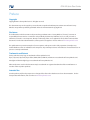
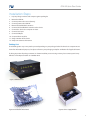
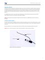
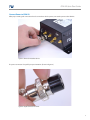
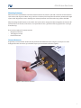
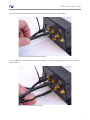
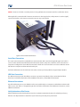
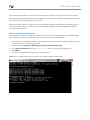
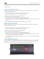
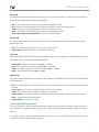
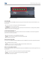
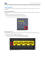
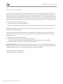
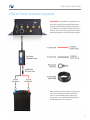
CIRA X2
Quick Start Guide
User Manual
Quick Start
CIRA X2 Quick Start Guide
Preface
Copyright
Copyright ©2013 Feeney Wireless LLC. All rights reserved.
This document may not be copied in part or otherwise reproduced without prior written consent from Feeney
Wireless except where specifically permitted under US and International copyright law.
Disclaimer
The information in this document is subject to change without notice. Feeney Wireless (“Feeney”) assumes no
responsibility for inaccuracies or omissions and specifically disclaims any liabilities, losses, or risks, personal or
otherwise, incurred as a consequence, directly or indirectly, of the use or application of any of the contents of this
document. For the latest documentation, contact your local supplier or visit us online at www.feeneywireless.com.
This publication may contain examples of screen captures and reports used in daily operations. Examples may
include fictitious names or individuals and companies. Any similarity to names and addresses of actual businesses or
persons is entirely coincidental.
Trademarks and Patents
Feeney and the Feeney logo are trademarks of Feeney Wireless LLC.
Skyus, Skyus 3G, Skyus 4G, Skyus Global, CIRA, CIRA X, CIRA X2, and Axiom are trademarks of Feeney Wireless LLC.
VaraSight and the VaraSight logo are trademarks of Feeney Wireless LLC.
Other trade names used in this document may be trademarks or registered trademarks of the manufacturers or
vendors of the respective products.
Intended Use
Use this product only for the purpose it was designed for; refer to the datasheet and user documentation. For the
latest product information, visit us online at www.feeneywireless.com.
CIRA X2 Quick Start Guide
Table of Contents
Overview...................................................................................................................................................................... 1
Intended Audience..................................................................................................................................................................................... 1
Scope............................................................................................................................................................................................................... 1
Specifications............................................................................................................................................................... 1
Environmental Specifications................................................................................................................................................................. 1
Power Specifications.................................................................................................................................................................................. 1
Antenna Specifications............................................................................................................................................................................. 2
3G Devices Antenna Requirements............................................................................................................................................. 2
4G Devices Antenna Requirements............................................................................................................................................. 2
Default Settings........................................................................................................................................................... 2
Device Information..................................................................................................................................................................................... 3
Installation Steps......................................................................................................................................................... 4
Packing List.................................................................................................................................................................................................... 4
Mount the CIRA X2..................................................................................................................................................................................... 5
Connect to Source Power......................................................................................................................................................................... 5
Connect Power to CIRA X2....................................................................................................................................................................... 6
Mounting Antennas................................................................................................................................................................................... 7
Connect Antennas...................................................................................................................................................................................... 7
Serial Port Connection.............................................................................................................................................................................. 9
USB Port Connection................................................................................................................................................................................. 9
Ethernet Connections................................................................................................................................................................................ 9
Verify Activation of the Device............................................................................................................................................................... 9
Verify Connection to the Internet......................................................................................................................................................... 10
Operation..................................................................................................................................................................... 11
Connect to the CIRA X2 Access Point................................................................................................................................................... 11
Logging into the CIRA X2 Modem........................................................................................................................................................ 11
Cellular Modem LED Functionality....................................................................................................................................................... 11
Power LED............................................................................................................................................................................................. 12
Activity LED........................................................................................................................................................................................... 12
Signal LED............................................................................................................................................................................................. 12
Network LED........................................................................................................................................................................................ 12
Access Point LED Functionality.............................................................................................................................................................. 12
Power LED (PWR)................................................................................................................................................................................ 13
Local Area Network LED (LAN 1- 4).............................................................................................................................................. 13
Wide Area Network LED (WAN)..................................................................................................................................................... 13
Wireless Local Area Network (WLAN).......................................................................................................................................... 13
Resetting the Device.................................................................................................................................................................................. 14
Resetting the Cellular Modem....................................................................................................................................................... 14
CIRA X2 Quick Start Guide
Resetting the Access Point.............................................................................................................................................................. 14
Contacting Feeney Wireless........................................................................................................................................ 15
Online Library............................................................................................................................................................................................... 15
Return and Warranty.................................................................................................................................................................................. 15
Further Specifications................................................................................................................................................................................ 15
FCC Compliance .......................................................................................................................................................... 16
CIRA X2 Power Installation Appendix........................................................................................................................ 17
CIRA X2 Quick Start Guide
Overview
Designed for harsh in-vehicle environments, the CIRA X2 integrates a cellular radio, GPS receiver, firewall, high-speed
processor, and Wi-Fi access point all in one device. The CIRA connects multiple devices using serial and Ethernet
peripherals for 802.11b/g/n Wi-Fi.
Intended Audience
This document is intended for users responsible for the initial set-up of the CIRA X2 and assumes the installer
possesses a basic working knowledge of computer networking, wireless routing and network administration.
For further information on using your device, please utilize the following documentation:
• CIRA X2 User Manual: Available via http://www.feeneywireless.com/documents
• ALEOS Configuration User Guide: Available via http://www.sierrawireless.com
Scope
This Quick Start Guide focuses on the installation and configuration of the CIRA X2. For information necessary above
and beyond this level of operation, please refer to the CIRA X2 User Manual.
Figure 1: CIRA X2 Front View
Specifications
Environmental Specifications
The CIRA X2 is designed to operate in a minimum ambient environment of -20°C or -4°F.
The CIRA X2 is designed to operate in a maximum ambient environment of 70°C or 158°F.
Power Specifications
Typical Power Consumption: 600mA at 12VDC, 1A peak.
The CIRA X2 uses an 11-34VDC input external vehicle power adapter which connects directly to the vehicle power
supply.
An optional custom 120V AC switching power supply can be purchased separately.
1
CIRA X2 Quick Start Guide
Antenna Specifications
The CIRA X2 will work with most standard active GPS antennas with an SMA male connector.
The CIRA X2 will work with most Dual-Band PCS cellular antennas with an SMA male connector.
3G Devices Antenna Requirements
The device has been designed to operate with the antennas having a maximum gain including loss of 5.1 dBi in the
800MHz Cellular Band and 4.15 dBi in the 1900 MHz PCS band.
The required antenna impedance is 50 ohms.
NOTE: Antennas having a gain greater than these values are strictly prohibited for use with this device.
4G Devices Antenna Requirements
Parameter
Requirements
Antenna System
External multi-band 2x2 MIMO antenna system (Ant1/Ant2)
Operating bands of Ant1 and Ant2
•
•
•
•
Voltage Standing Wave Ratio (VSWR) of
Ant1 and Ant2
1:1(ideal)
< 2.5:1 (recommended)
Total radiated efficiency of Ant1 and
Ant2
>50% on all bands
Mean Effective Gain of Ant1 and Ant2
(MEG1, MEG2)
>= -3 dBi
Ant1 and Ant2 Mean Effective Gain
Imbalance | MEG1/MEG2 |
< 2dB for MIMO operation
< 6 dB for diversity operation
Maximum antenna gain
Must not exceed antenna gains due to RF exposure and ERP/EIRP
limits as listed in the module’s FCC grant.
700 – 960 MHz
1710 – 1990 MHz
2100 – 2170 MHz
2500 – 2700 MHz
Default Settings
The default 802.11 Wireless settings are shown below:
• SSID: cira-<nnnn>, where <nnnn> is a 4-digit unique identifier taken from the last four characters of the unit’s
MAC address.
• WPA Preshared Key Password: feeneyap
• Guest WLAN: Disabled
2
CIRA X2 Quick Start Guide
The Network Default settings are shown below:
•
•
•
•
•
•
•
•
•
•
•
Access Point IP address: 192.168.1.1
Access Point Web Interface Port: 8080
Access Point Ethernet/Wi-Fi access URL: http://192.168.1.1:8080
DHCP: Enabled, client address pool begins at 192.168.1.33
Firewall: Enabled
Remote Management URL: http//<modem public ip>:8080 or :9191 (:8080 provides access to the router, and
:9191 provides access to the modem.)
Modem IP address: 192.168.13.31
Modem Web Interface Port: 9191
Modem access URL: http://192.168.13.31:9191
Modem Administrator User Name: user
Modem Password: 12345
Device Information
Figure 2 shows the structure of the label for a particular device, your label may be different when specific to your
order/installation. The image is supplied to provide you with a basis for understanding where to locate your
information for configuration and troubleshooting instances.
Device Serial Number
Modem Serial Number
Mobile Equipment Identifier
Subscriber Identity Module ID Number
Media Access Control Address
Figure 2: CIRA X2 Product Label
3
CIRA X2 Quick Start Guide
Installation Steps
1.
2.
3.
4.
5.
6.
7.
8.
9.
10.
11.
12.
Inspect package contents and compare against packing list
Mount the CIRA X2
Connect power to the source (battery)
Connect power to the CIRA X2
Mount Cellular/GPS/Wi-Fi antennas
Connect Cellular/GPS/Wi-Fi antennas to the device
Connect the device to a computer or router
Connect Serial port
Connect USB port
Connect Ethernet cables
Verify activation of the device
Verify connection to the Internet
Packing List
The following items may or may not be present depending on your packaged order. The three basic components are
shown for informational purposes, but please reference your packaging receipt for verification of all applicable items.
If, during inspection of package contents, it is determined that you are missing an item, please contact your Feeney
Wireless Service Representative at 1-800-683-4818.
Figure 3: CIRA X2 Device
Figure 4: Cellular/GPS Antenna Kit
Figure 5: Power Supply Module
4
CIRA X2 Quick Start Guide
Mount the CIRA X2
Your device should be mounted in a position that allows easy access for connections so that the cables are not bent,
constricted, in close proximity to wiring for other radio or high current devices, or exposed to extreme temperatures.
The LEDs on the front panel should be visible for ease of operational verification. Ensure that the location provides
adequate airflow around the modem but that it is kept free from direct exposure to the elements, such as sun, rain,
dust, etc.
In a mobile location, such as a car or truck, ensure the location is secure both against abrupt movements of the
vehicle and from other items coming into contact with the CIRA X2.
NOTE: Never install your device under the engine hood of your vehicle – the CIRA X2 will overheat and become
damaged.
Connect to Source Power
The power cable positive lead (white) should be connected to the battery or power source positive terminal on a fuse
box. The power cable negative (black) lead should be connected to the battery or power source negative terminal on
a fuse box.
For further information on hooking up power, refer to the “CIRA X2 Power Installation Appendix” on page 17.
NOTE: The use of a chassis ground can result in reduced performance and possibly device failure.
Negative Lead
Positive Lead
Figure 6: Power Leads to Vehicle Power
5
CIRA X2 Quick Start Guide
Connect Power to CIRA X2
After proper routing and connections have been made to vehicle power, connect the power to the CIRA X2.
Figure 7: Power Connected to Device
The power connector is keyed for proper orientation. (Shown in Figure 8)
Figure 8: Keyed Connector for Power
6
CIRA X2 Quick Start Guide
Mounting Antennas
Antennas must be installed with a minimum of 20cm between the antennas and with a minimum of 20cm between
each antenna and all persons. When using a cable to an antenna placed away from the modem, minimize the length
of your cable. All gain from a more advantageous antenna placement can be lost with a long cable to the CIRA.
When mounting the GPS Antenna in the vehicle, the less the cable is wrapped and bound together, the better it will
perform. Place it on the roof, on the dash, or rear panel where it has a good view of the sky (greater than a 90 angle
view of the sky).
There are three options for antenna mounts:
• Magnetic roof-mount
• Through glass-mount
• Permanent mount
Connect Antennas
If applicable, connect the GPS antenna directly to the threaded SMA connector. In Figure 9, the zip tie is used to
distinguish the GPS connection; you shouldn’t expect your connection to have this signifier.
Figure 9: GPS Antenna Connection
7
CIRA X2 Quick Start Guide
Connect the Primary Cellular Antenna cable directly to the antenna connector on the CIRA X2.
Figure 10: Primary Cellular Antenna Connection
If you are utilizing the Secondary Cellular Antenna connection, connect the cable directly to the antenna connector
on the CIRA X2.
Figure 11: Secondary Antenna Connection
8
CIRA X2 Quick Start Guide
NOTE: In instances in which a secondary device is being utilized, this connection would be used for that device.
When applicable, connect the Wi-Fi antenna connections. In the image below, a whip antenna is used to signify
separate connections. Your antenna connections may or may not be similar.
Figure 12: Wi-Fi Antenna Connections
Serial Port Connection
This 9-pin connector provides standard RS-232 communication with a standard straight-through serial cable. It
can be used to communicate with industrial machines like motors, computers, controllers or for connection to a
computer to configure the device with AT commands. The RS-232 serial connection can also be utilized to stream
GPS data to a computer or tablet attached to this port.
For further information on the Serial Port Connection, contact your Feeney Wireless Support Representative.
USB Port Connection
This USB connector provides the ability to connect a separate Feeney Wireless Skyus 3G modem for failover
allowances. For further information on the USB Port Connection, see the CIRA X2 User Manual.
Ethernet Connections
Any of the Ethernet ports on your CIRA X2 can be connected directly to a computer or other Ethernet device with
either a cross-over cable or a straight-through cable. For further information on the Ethernet Connections, see the
CIRA X2 User Manual.
Verify Activation of the Device
While all CIRA X2 models should perform over the air activation automatically, please check with your Feeney
Wireless Sales Representative to determine if your device has previously been provisioned.
9
CIRA X2 Quick Start Guide
If it has been determined that your device hasn’t been activated, ensure that the cellular antennas are connected
prior to powering the device up for the first time. Supply power to the device and wait for approximately 15 minutes
for over the air provisioning of the device to proceed.
For Verizon and ATT customers, it may be necessary to manually configure your APN to the value provided by your
carrier representative. This can be done in the modem web interface, please contact Feeney Wireless technical
support for further guidance.
Verify Connection to the Internet
Once activation is complete, it is helpful to ensure that you have a live connection to the internet. By following the
steps listed below, you can be sure that your device is communicating to the outside world.
1. Ensure that you are utilizing the CIRA X2 as your Internet connection, either by connecting an Ethernet cable to
the LAN connection or associating to the Wi-Fi.
2. On your computer, Click Start> (All) Programs>Accessories> Command Prompt
3. In the Command Prompt Window, type Ping 4.2.2.1 (This is an open-for-public DNS server)
4. Press ENTER
5. Ensure you receive the following response, as seen in Figure 13.
NOTE: If you see “Request time out”, your device is not communicating over the Internet.
Figure 13: Command Prompt - Ping
10
CIRA X2 Quick Start Guide
Operation
Connect to the CIRA X2 Access Point
After the initial power up, to see if the device is properly connected and operating correctly, you can log-in to the
device via the methods listed below:
• Connect an Ethernet cable from a computer directly the CIRA X2 LAN connection.
• Associate to the CIRA X2 Wi-Fi via the default settings, stated on page 2.
Once you have connected to the device perform the following steps:
1. Open a web browser on your connected device.
2. In the browser’s address bar, enter the IP Address: http://192.168.1.1:8080
3. If it is the initial log-in, use the default password (feeneyap). If the device’s log-in password has changed, use that
password.
4. Use the CIRA X2 User Manual for instruction on configuring the device’s access point.
Logging into the CIRA X2 Modem
After the initial power up, to see if the device is properly connected and operating correctly, you can log-in to the
device via the methods listed below:
• Connect an Ethernet cable from a computer directly the CIRA X2 LAN connection.
• Associate to the CIRA X2 Wi-Fi via the default settings, stated on page 2.
Once you have connected to the device perform the following steps:
1. Open a web browser on your connected device.
2. In the browser’s address bar, enter the IP Address: http://192.168.13.31:9191
3. If it is the initial log-in, use the default user name/password combination (user/12345). If the device’s log-in user/
password combination has changed, use that combination.
4. Use the ALEOS Configuration User Guide available at http://www.sierrawireless.com for instruction on configuring
the device’s modem.
Cellular Modem LED Functionality
For ease of installation, a brief description of LED functionality is displayed below for assistance. In this section, this
document will cover the bank of LEDs displayed in the lower section of the housing highlighted by the red outline
below in Figure 14. These LEDs are signal indicators for the functionality of the cellular modem.
Figure 14: Cellular Modem LEDs
11
CIRA X2 Quick Start Guide
Power LED
The Cellular Modem Power LED monitors the input power or shows if the device sees a GPS signal. The Power LED is
located on the far right of the cellular modem LED bank.
•
•
•
•
•
Off – there is either no power, or the source of power is ≥ 36VDC or ≤ 9VDC.
Red – the device is not operational. This could represent a failure or lower power to the device.
Yellow – the device is entering low power mode or system low level boot.
Green – the device is connected to nominal power and is operating normally.
Green (with a momentary yellow flash) – device has received a GPS fix.
Activity LED
The Cellular Modem Activity LED shows the radio’s activity. The Activity LED is located directly left of the Cellular
Modem Power LED.
• Off – this is the LEDs normal appearance when no activity is present.
• Flashing Green – the cellular radio is transmitting or receiving.
Signal LED
The Cellular Modem Signal LED shows the cellular network’s signal level. The Signal LED is located directly left of the
Activity LED. (RSSI = Received Signal Strength Indication)
•
•
•
•
Flashing Red – There is no signal present. (RSSI > -110 dBm)
Red – A bad signal level is present (-100 dBm ≥ RSSI ≤ -110 dBm)
Yellow – A marginal signal level is present (-85 dBm ≥ RSSI ≤ -100 dBm)
Green – A good signal is present (RSSI ≤ -85 dBm)
Network LED
The Cellular Modem Network LED monitors the cellular network. The Network LED is located on the far left of cellular
modem LED bank.
• Red – No cellular network is present or the device is in radio passthru mode. (There is no network coverage at the
location)
• Flashing Red – The device is attempting to connect to the cellular network.
• Yellow – The cellular network is found and the device is connecting.
• Flashing Yellow – The cellular network is unavailable. (The device was unable to authenticate on the network)
• Green – Connected to the cellular network.
• Flashing Green – The device is roaming.
Access Point LED Functionality
For ease of installation, a brief description of LED functionality is displayed below for assistance. In this section, this
document will cover the bank of LEDs displayed in the upper section of the housing highlighted by the red outline in
Figure 15.
These LEDs are signal indicators for the functionality of the access point. The color of the LEDs will remain green, the
descriptions below will detail the state of the LED.
12
CIRA X2 Quick Start Guide
Figure 15: Access Point LEDs
Power LED (PWR)
The Access Point Power LED (PWR) monitors the input power. The Power LED is located on the far left of the access
point LED bank.
•
•
•
•
On – The access point is receiving power and functioning properly.
Slow Blinking – The access point is booting.
Fast Blinking – The reset button (for the access point) has been held and the unit is resetting to factory defaults.
Off – The access point is not receiving power.
Local Area Network LED (LAN 1- 4)
The Access Point LAN LEDs (LAN 1 - 4) monitor the LAN connections. The LAN LEDs are located to the right of the
power LED and are labeled sequentially.
• On – The access point has a successful Ethernet connection.
• Blinking – The access point is sending/receiving data through the LAN.
• Off – The LAN is not connected.
Wide Area Network LED (WAN)
The the Access Point WAN LED monitors the WAN connection. The WAN LED is located to the right of the LAN 4 LED.
• On – The WAN connection is enabled.
• Blinking – The access point is negotiating a WAN connection with the cellular modem.
• Off – The WAN connection is not ready or has failed.
Wireless Local Area Network (WLAN)
The Access Point WLAN LED monitors the WLAN connection(s). The WLAN LED is located on the far right of the access
point LED bank.
• On – The access point is ready, but not sending/receiving data through the WLAN.
• Blinking – The access point is sending/receiving data through the WLAN.
• Off – WLAN is not ready or has failed.
13
CIRA X2 Quick Start Guide
Resetting the Device
There are two methods available for performing resets on the CIRA X2, one for the cellular modem and one for the
access point.
Resetting the Cellular Modem
The Reset button, located to the lower right of the modem status LEDs on the front of the CIRA X2, has two primary
functions:
1. Powers up or reboots the device; briefly press in and release.
2. Returns the modem configuration settings to their factory defaults.
a. Press in & hold for 7 – 8 seconds until all LEDs are flashing yellow.
Figure 16: Cellular Reset Button
Resetting the Access Point
The Reset button, located to the left of the LAN connections on the rear of the CIRA X2, has two primary functions:
1. Reboots the access point; briefly press in and release.
2. Returns the access point configuration settings to their factory defaults.
a. Press in & hold for 5 – 15 seconds until the power light begins flashing.
Figure 17: Access Point Reset Button
14
CIRA X2 Quick Start Guide
Contacting Feeney Wireless
For help with installing, operating, maintaining, and troubleshooting this product, refer to this document and any
other documentation provided.
If you still have questions, contact us during business hours:
Monday through Friday, excluding holidays, between 8 a.m. and 5 p.m. Pacific Time.
Support E-mail
Telephone
Website
Mailing Address
[email protected]
(800) 683-4818
www.feeneywireless.com
P.O. Box 2549, Eugene, OR 97402
When contacting technical support, please have the following information on-hand:
1. Serial Number
2. Date that you received your device
3. Brief description of the problem
Online Library
For other documentation, see our online document library at:
http://feeneywireless.com/documents
Return and Warranty
Feeney Wireless offers a standard one-year warranty on all hardware. For returns or warranty information, call our 800
number.
Further Specifications
For more specifications please see the CIRA X2 User Manual.
15
CIRA X2 Quick Start Guide
FCC Compliance
This equipment has been tested and found to comply with the limits for a Class B digital device, pursuant to part 15
of the FCC rules. These limits are designed to provide reasonable protection against harmful interference when the
equipment is operated in a residential environment. This equipment generates, uses, and can radiate radio frequency
energy and, if not installed and used in accordance with the instruction manual, may cause harmful interference to
radio communication. Feeney Wireless does not guarantee that interference will not occur in a particular installation.
Operation is subject to the following conditions:
a. This device may not cause harmful interference.
b. This device must accept any interference received, including interference that may cause undesired operation.
Changes or modifications not expressly approved by the party responsible for compliance could void the user’s
authority to operate the equipment.
If this equipment does cause harmful interference to radio or television reception, which can be determined by
tuning the equipment off and on, the user is encouraged to try and correct the interference by one or more of the
following measures:
a. Reorient or relocate the receiving antenna.
b. Increase the distance between the equipment and the receiver.
c. Connect the equipment to outlet on a circuit different from that to which the receiver is connected.
d. Consult the dealer or an experienced radio/TV technician for help.
Exposure to RF radiation - To comply with FCC RF exposure compliance requirements, for mobile configurations, a
separation distance of at least 20cm must be maintained between the antenna of this device and all persons. Do not
collocate or operate this device in conjunction with any other antenna or transmitter.
Contains TX module FCC ID: N7N-MC7750
Contains TX Module IC: 2417C-MC7750
Document number 25-52-001-04 Rev E1
16
CIRA X2 Quick Start Guide
CIRA X2 Power Installation Appendix
IMPORTANT: Feeney Wireless recommends that
the power supply be connected for both power
and ground connections directly to the battery
or a common low resistance location such as the
fuse box. The use of a chassis ground can result in
reduced performance and possible device failure.
When entering the vehicle engine compartment
with power and ground cable ensure that the
cable is covered with high temperature split
tubing, and or use automotive wiring designed
for high temperature environments.
17