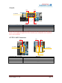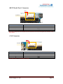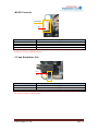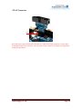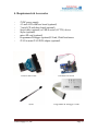
1
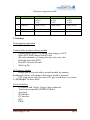
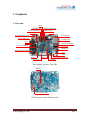
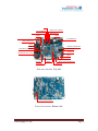
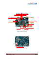
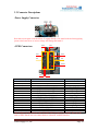
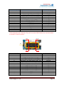
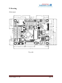
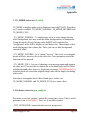
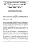
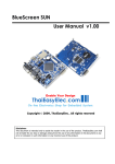
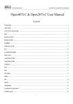
mini SUN7
User Manual
v1.00
Revision History
Version
1.00
Date
4 Feb 2012
Venus Supply Co., Ltd.
Changes
Original version
Page 2
Contents
1 Introduction
2 Features
2.1 Hardware
2.2 Software
3 Peripherals
3.1 Layouts
3.2 Connector Descriptions
4 Requirements & Accessories
5 Getting Start
6 Example Code Descriptions
6.1 Files & Folders
6.2 Project Setting
7 Programming, Debugging and Command Line Interface
7.1 JTAG Interface
7.2 Serial Ports
7.3 Command Line Interface
8 GUI Script
8.1 Why Using GUI Script?
8.2 Features
8.3 Script Loading Mechanism
8.4 Application Programming Interface
9 Drawing
4
5
5
6
8
8
10
17
19
20
20
21
22
22
25
27
32
32
33
35
36
38
Appendix
1 TS_MODE
2 Pen Status
3 Color Depth Selection Guide
3.1 Color Depth vs. Memory & Speed
3.2 Palletized Color
4 Images and Fonts Generating
38
38
39
40
40
41
41
Venus Supply Co., Ltd.
Page 3
1. Introduction
Mini SUN7 are resistive touch panel controller board comes with NXP‟s
powerful ARM Cortex-M3 LPC1788, the LCD-controller integrated MCU.
It‟s the upgraded and optimized version of BlueScreen SUN7 which uses
NXP‟s ARM7 LPC2478. Despite the change of MCU chipset, on-board
switching power supply is removed and the MP3 decoder circuit is added,
plus more peripherals and GPIO ports. All in the smaller 4-layer PCB with
slimmer dimension with lower price!
Integrated with all necessary peripherals, Mini SUN7 is aimed to be the core
controller board for vending machine, kiosk and industrial control panel.
The 4.3-inch and 7-inch touch screen TFT LCDs from our website are
available for using with the board.
Mini SUN7 is assembled with 3 official versions, full-option, low-cost and
basic versions. The differences are Ethernet, MP3 decoder circuit and
SDRAM size. See section 2 “Features” for more details.
Using ARM Cortex-M3 running up to 120MHz, the firmware can be
developed in various ways. An alternative we provide is non-OS based using
our easy proprietary GUI development method called GUI Script and our
software, SUN7 Studio. It‟s well suited for not so complex graphical
applications. Please see section 8 “GUI Script” for more details.
Furthermore, using the same software structure with SUN7, the project
running with SUN7 can be ported to Mini SUN7 easily.
Mini SUN7 are manufactured with Lead-Free process and all materials on
boards are Lead-Free.
Venus Supply Co., Ltd.
Page 4
2. Features
2.1 Hardware
NXP‟s ARM Cortex-M3 LPC1788
12 MHz crystal
Maximum of 64 MB memory with 2 of 16-bit EtronTech‟s
EM63A165TS-5G SDRAM (32-bit)
Connector for 800x480 pixels (wide screen 7”) TFT LCD and 4-wire
resistive touch screen panel
Touch screen controller IC, STMPE610
Micro SD card socket (SPI interface) supports SDHC (high capacity
type)
On board 8KB EEPROM (the last 128 bytes are reserved for screen
calibrated parameters) (There is also on-chip 4KB EEPROM in LPC1788)
Selectable UART0 with LVTTL-level (3.3V with 5V tolerant) or
RS232-level for command line interface and in-system programming
Connectors for LVTTL-level UART1 UART2 and UART3
RS485 interface using SN75176 and 4-pin 2.54 mm connector
1 port ThaiEasyElec‟s module connector consisting of SPI and UART
signals from MCU, can be configured as 7 GPIO ports (this UART port is
shared with RS485 interface)
22 GPIOs
One USB host interface with USB type A connector and power switch
IC LM3526M-L
One USB device interface with mini USB type B connector
Built-in DP83848 Ethernet and RJ45 connector (full-option only)
Built-in VS1011E MP3 decoder with 3.5 mm headphone jack (fulloption and low-cost only)
Mini JTAG connector for programming and debugging
5VDC power supply terminal
Footprint for CAN PHY TJA10xx (not installed)
Footprint for SPI FLASH AT45DBxx (not installed)
Venus Supply Co., Ltd.
Page 5
Hardware comparison table
NO.
1
Feature
GPIOs
2
SDRAM
Full-option
-12 (P17)
-10 (P6)
-7 (P8)
64MB (32-bit)
3
4
Ethernet
MP3 decoder
On-board
On-board
Low-cost
-12 (P17)
-10 (P6)
-7 (P8)
32MB (16-bit)
Basic
-12 (P17)
-10 (P6)
-10 (P8)
32MB (16-bit)
On-board
-
2.2 Software
Demonstrating application
GUI script demo
Command line interface software module
Capture images from C328 camera, show images on LCD
Show JPEG, BMP images from SD card
SD card commands e.g. change directory, list, read, write
Read and write time (RTC)
Play MP3 file from SD card
Write log file
GUI software module
Design your screen with object oriented method, the running
background software will manage which object should be operated
GUI script engine, help you create GUI, play sound easier, see section
8 “GUI Script” for more detail
Low level drivers
LCD driver with 24-bpp, 16-bpp, 8-bpp (palletized)
Touch screen controller (STMPE610) driver
Serial port
SPI interface
I2C interface
RTC
PWM
Venus Supply Co., Ltd.
Page 6
3. Peripherals
3.1 Layouts
GPIOs
CAN CONNECTOR
mini-JTAG CONNECTOR
SERIAL PORT 0 (RS232)
RESET SWITCH
UART 0
UART 3
BATTERY HOLDER FOR RTC
DC CONNECTOR
RS485 CONNECTOR
ETHERNET PORT
GPIOs
GPIOs
USB HOST CONNECTOR
EINT0 SWITCH (FOR ISP)
STATUS LED
USB DEVICE
HEADPHONE JACK (3.5mm)
UART 1
UART 2
VS1011E
SDRAM
LCD SOCKET
TOUCH SCREEN CONNECTOR
POWER LED
Full-option version: Top side
SDRAM
micro SD CARD SOCKET
Full-option version: Bottom side
Venus Supply Co., Ltd.
Page 7
GPIOs
CAN CONNECTOR
mini-JTAG CONNECTOR
SERIAL PORT 0 (RS232)
RESET SWITCH
UART 0
UART 3
BATTERY HOLDER FOR RTC
DC CONNECTOR
RS485 CONNECTOR
GPIOs
USB HOST CONNECTOR
GPIOs
EINT0 SWITCH (FOR ISP)
STATUS LED
USB DEVICE
HEADPHONE JACK (3.5mm)
UART 1
UART 2
VS1011E
SDRAM
LCD SOCKET
TOUCH SCREEN CONNECTOR
POWER LED
Low-cost version: Top side
micro SD CARD SOCKET
Low-cost version: Bottom side
Venus Supply Co., Ltd.
Page 8
GPIOs
CAN CONNECTOR
mini-JTAG CONNECTOR
SERIAL PORT 0 (RS232)
RESET SWITCH
UART 0
UART 3
DC CONNECTOR
BATTERY HOLDER FOR RTC
RS485 CONNECTOR
GPIOs
GPIOs
USB HOST CONNECTOR
EINT0 SWITCH (FOR ISP)
STATUS LED
USB DEVICE
UART 1
UART 2
SDRAM
LCD SOCKET
TOUCH SCREEN CONNECTOR
POWER LED
Basic version: Top side
micro SD CARD SOCKET
Basic version: Bottom side
Venus Supply Co., Ltd.
Page 9
3.2 Connector Descriptions
-Power Supply Connector
Note that as some parts on the board use 5V supply directly. Care must be taken when supplying
power to the board. Over or inverse voltage will damage the board!!!
Pin 2
-GPIO Connectors
Pin 1
Pin 1
Pin 2
P8
P6
Pin 16
Pin 15
Connector P8 (Pin)
1
2
3
4
5*
6*
7
8*
9
10
11
12
13
14
15
16
Pin 16
Name Pin
3.3V
GND
5V
P5[0],A[24],MOSI2,MAT2[2]
P2[26],CKEOUT2,MAT3[0],MISO0
P2[27],CKEOUT3,MAT3[1],MOSI0
P5[3],RXD4,SCL0
P2[22],DYCS2,CAP3[0],SCK0
P5[4],U0_OE,MAT3[3],TXD4
P2[23],DYCS3,CAP3[1],SSEL0
P2[0],PWM1[1],TXD1,LCDPWR
P2[14],CS2,CAP2[0],SDA1
P2[15],CS3,CAP2[1],SCL1
5V
GND
3.3V
Name in project
MD2_RST_PIN
MD2_MISO_PIN
MD2_MOSI_PIN
RXD4_PIN
MD2_SCLK_PIN
TXD4_PIN
MD2_CS_PIN
MD2_IN_PIN
MD2_IO_PIN
MD2_OUT_PIN
*Pins dedicated for SPI functions when VS1011E (MP3 decoder IC) is installed. They can‟t be
used as GPIO. But the user can connect them to external IC with SPI interface.
Venus Supply Co., Ltd.
Page 10
Connector P6 (Pin)
1
2
3
4
5
6
7
8
9
10
11
12
13**
14**
15
16
Name Pin
3.3V
5V
P0[23],AD0[0],I2SRX_CLK,CAP3[0]
P0[24],AD0[1],I2SRX_WS,CAP3[1]
P1[31],USB_OVRCR2,SCK1,AD0[5],SCL0
P0[12],USB_PPWR2,MISO1,AD0[6]
P1[2],MCICLK,PWM0[1]
P5[1],A[24],MISO2,MAT2[3]
P2[25],CKEOUT1
P4[27],BLS1
P4[18],A[18]
P2[10],EINT0,NMI
SDA0
SCL0
GND
GND
Name in project
AD0_PIN
AD1_PIN
AD5_PIN
AD6_PIN
IO12_PIN
IO13_PIN
IO14_PIN
IO15_PIN
IO16_PIN
S2_PIN
**Pins dedicated for I2C functions. They can‟t be used as GPIO. But the user can connect them
to external IC with I2C interface.
Pin 2
Pin 16
P8
Pin 1
Connector P17 (Pin)
1
2
3
4
5
6
7
8
9
10
11
12
13
14
15
16
Pin 15
Name Pin
3.3V
5V
P0[4],I2SRX_CLK,RD2,CAP2[0]
P0[5],I2SRX_WS,TD2,CAP2[1]
P0[6],I2SRX_SDA,SSEL1,MAT2[0],RTS1
P0[7],I2STX_CLK,SCK1,MAT2[1],RTC_EV0
P0[9],I2STX_SDA,MOSI1,MAT2[3],RTC_EV2
P0[17],CTS1,MISO0
P1[3],MCICMD,PWM0[2]
P1[5],MCIPWR,PWM0[3]
P1[6],MCIDAT0,PWM0[4]
P1[7],MCIDAT1,PWM0[5]
P1[11],MCIDAT2,PWM0[6]
P1[13]
GND
GND
Venus Supply Co., Ltd.
Name in project
IO0_PIN
IO1_PIN
IO2_PIN
IO3_PIN
IO4_PIN
IO5_PIN
IO6_PIN
IO7_PIN
IO8_PIN
IO9_PIN
IO10_PIN
IO11_PIN
Page 11
-Console
Pin 2
Pin 8
P7 (UART0)
Pin 1
Connector UART0 (Pin)
2
4
5
7
Pin 7
Name Pin
GND
TXD0
RXD0
GND
Note that connecting the console port with USB-to-serial in the wrong way will not damage any
devices. Correct connection lights LED4. This connection style is designed so cross connection
can be easily established.
-LVTTL UART Connectors
Pin 1
Pin 1
Pin 1
P5 (UART3)
P14 (UART1)
P15 (UART2)
Connector UART 1,2,3 (Pin)
1
2
3
4
Venus Supply Co., Ltd.
Name Pin
3.3V
RXDx
TXDx
GND
Page 12
-RS232 Serial Port 1 Connector
Pin 1
P1 (RS232)
Connector P1 (Pin)
1
2
3
4
Name Pin
5V
RXD0
TXD0
GND
Note that a jumper must be installed on P9 to use RS232-level for serial port0. See section 7.2 for
more detail.
-CAN Connector
Pin 1
P3 (CAN)
Connector P3 (Pin)
1
2
3
4
Name Pin
5V
CANL
CANH
GND
Note that CAN IC is not installed by default.
Venus Supply Co., Ltd.
Page 13
-RS485 Connector
P12 (RS485)
Pin 1
Connector P12 (Pin)
1
2
3
4
Name Pin
5V
A
B
GND
Note that the termination resister for end node is not installed by default. And a jumper must be
installed on P18 to use RS485 interface.
-3.5 mm Headphone Jack
Pin 1
P16
Connector P16 (Pin)
1
2
3
Name Pin
Left
GBUF
Right
Note that the signals on audio jack are intended to be used with headphone. Please contact us if
you need to connect it with a speaker.
Venus Supply Co., Ltd.
Page 14
-LCD Connector
Note that LCD connector is top-contact type. The pair cable must be installed correctly by turning
up the contact side.
-Touch Screen Connector
Pin 1
P10
Connector P10 (Pin)
1
2
3
4
Name Pin
YD
XR
YU
XL
Note that touch screen connector can be connected in 2 ways. Once the board is calibrated, it
remembers the connection way. Whenever it‟s swapped over, the board needs to be recalibrated.
Venus Supply Co., Ltd.
Page 15
-JTAG Connector
Pin 1
Note that as the board is designed for compact size, small mini-JTAG connector is used in place
of standard 20-pin JTAG connector. The user needs JTAG to mini-JTAG adapter to program and
debug the target board.
Venus Supply Co., Ltd.
Page 16
4. Requirements & Accessories
-
5VDC power supply
4.3-inch LCD with base board (optional)
7-inch LCD with base board (optional)
Serial cable (optional) or USB to serial (LVTTL) device
Stylus (optional)
micro SD card (optional)
Programmer/Debugger (optional):ULink, Ulink2 and mores
JTAG to mini-JTAG PCB adapter (optional)
JTAG to mini-JTAG
Stylus
Venus Supply Co., Ltd.
USB mini B to Serial
Programmer & Debugger Ulink2
Page 17
4.3” LCD with base board
7” LCD with base board
Venus Supply Co., Ltd.
Page 18
5. Getting Start
The board can be powered via 5VDC terminal. There is no protection so
please check input voltage and polarity carefully.
The on-board firmware from our store is for 7” LCD. If it is used with 4.3”
LCD, firmware should be compiled and programmed to the board first.
Powering up, the LCD shows “Press the screen to recalibrate within 1
second”. At this state, if you want to recalibrate the screen, press on it.
Anyway, the board is pre-calibrated so users don‟t need to do it again.
Calibration is needed when LCD size is changed or touch panel connector is
not connected in the same way when the board was calibrated.
Without recalibration, calibrated parameters are read from last 128 bytes of
EEPROM. These parameters are used to calculate which point the screen is
pressed. After that, the example application starts.
In order to recalibrate the screen, there would be 5 points on the screen to be
pressed. For accuracy, please touch it slowly and a stylus should be used.
Using 5 points for calibration, the user must press the points accurately until
the error is acceptable. Then the board needs to be reset.
There are example projects provided on our websites
(www.thaieasyelec.com and www.thaieasyelec.net). They contain many files
so please take a look at section 6 “Example code descriptions” to
understand source code structure and to have the project set correctly. And
then, to download firmware to the board, see section 7 “Programming,
Debugging and Command line interface” about how to set tools for
development.
Venus Supply Co., Ltd.
Page 19
6. Example Code Descriptions
Contents below are referenced to graphic library example; there may be
some differences in other examples.
6.1 Files & Folders
In latest generation of our example code source files are separated to folders
for clarity. This section tells you which one you should look for if you‟re
finding something and tell you what is contained in files.
-root: contains necessary files
startup_LPC17xx.s: start up file for LPC1788
main_cm3.c: contains necessary hardware start up functions, for
example; SDRAM, timers
hw_mini_sun7.h: contains ports and devices definition for mini SUN7
app_config.h: includes all header files and has many configurations
that can be modified for each application, this file is included on the top of
every source files
-drv_lpc24xx: contains driver files for LPC1788 including SPI, I2C, PWM,
serial port, RTC and LCD controller
-drv_onb: contains driver for devices on the board including EEPROM,
touch screen controller STMPE610
-drv_xdev: contains driver for external module including VS1011E module
and C328 camera
-sw_mod: contains software modules or middleware
console.c: receives characters from console port and provides echo
then check if characters match command created in app_console.c.
font_engine.c: prepare buffer to be printed on the LCD
font_thai_plugin.c: same with font_engine.c but with extra language
in the project, other language font engine can be adapted from this one
obj_lib.c: manages standard objects such as check boxes, buttons,
keypads, textboxes and etc.
Venus Supply Co., Ltd.
Page 20
screen_obj.c: manages objects on the screen, find which one is
pressed or released can call associated functions
script_reader.c: manages reading script from SD card, characters are
then sent to console so any console command can be put in the script
touch_engine.c: manages calibration and calculate point from data
read from touch screen controller
utils_custom.c: contains useful general functions being used in many
other source files
jpeg_decoder.c: manages jpeg decoding
log_manager.c: manages logging
-app: contains application specific source files and header files
app_bs_sun_demo.c: contains application specific initialization and
routines
app_console.c: contains command string and functions to be called
when commands are entered
app_sd_ui.c: contains SD card associated functions
app_scr_func.c: contains screen associated functions
-fonts: contains arrays that are used to generate characters, these arrays will
be stored in FLASH memory
-images: contains arrays of binary data ready to be shown on the LCD, these
arrays will be stored in FLASH memory
-fat_sd: contains FAT file system library modified from FatFs
6.2 Project Setting
The example code can be run on mini SUN7 board with any option (except
the LCD size), to make it possible many “#define” are used and it‟s
necessary for users to know how to set so the board run as expected.
See at the head of app_config.h, first of all, pins are defined in a header file.
The user doesn‟t need to do anything with this.
//hardware configuration, which board you’re using
#include “hw_mini_sun7.h” // use this line if you’re using a SUN7
Venus Supply Co., Ltd.
Page 21
Now select the LCD size. Only Graphic library demo supports both LCD
size.
//which LCD you’re using
//#define LCD_SIZE_4_3 //for 4.3-inch LCD
#define LCD_SIZE_7 //for 7-inch LCD
Then select color depth, only Graphic library demo supports all options.
Only with 8-bpp mode, you can set the intensity which makes all color
lighter.
//color depth, if you’re using board with 1 SDRAM, 16 or 8 should
be used
//#define COLOR_DEPT
24
//#define COLOR_DEPT
16
#define COLOR_DEPT
8
//palettized 256 colors
//#define COLOR_DEPT_8_INTENSITY_SET //set intensity bit, used
only with 8-bpp palette mode
The last one (at the half of file), how many SDRAM on the board, one with
32MB is enough for many applications. If your board has 2 (64MB) please
comment the line out.
//SDRAM config
#define SINGLE_SDRAM //comment this line out if your board has 2
SDRAM ICs
Venus Supply Co., Ltd.
Page 22
7. Programming, Debugging and Command Line Interface
7.1 JTAG Interface
Mini SUN7 supports JTAG interface for debugging and programming.
Many programmers can be used corresponding to your IDE.
For uVision software, on the target‟s option select „Debug‟ and configure
the flash programmer as follow.
Venus Supply Co., Ltd.
Page 23
Back to target‟s option select Utilities and configure as follow.
Venus Supply Co., Ltd.
Page 24
Select setting and add programming algorithm as follow.
7.2 Serial Ports
Command line interface can be connected using UART0 (as CONS_SER is
defined to „0‟ in app_config.h). Anyway, the board provides UART0 in 2
types; RS232 and LVTTL. There is a jumper (P9) to be installed, see
pictures below.
Use RS232 for UART0
Venus Supply Co., Ltd.
Use LVTTL for UART0
Page 25
To communicate the board with command line interface, HyperTerminal or
compatible software can be used. Set the COM port as follow.
The serial port 0 also served for ISP (In-system programming), which user
can use software like FlashMagic to program the MCU. To do this, press and
hold S2, reset the board and then release S2. Now the MCU should starts
with ISP boot loader.
When programming finished reset the board again without holding S2.
Venus Supply Co., Ltd.
Page 26
7.3 Command Line Interface
Example code provides plenty of commands, these commands allow users to
test peripherals and set many necessary parameters. Also, user can make a
script file with setting commands on it then let the board read and do at the
start (by default, make a text file “main.txt” and put it in a folder named “sr”
on the root of SD card, that‟s /sr/main.txt). We hope that users can develop
project faster with them. This section provides information on how to use
these commands.
First to know is, console engine accepts both uppercase and lowercase
characters, just for the command word. And you can put any space
characters („ ‟) before or between arguments. Backspace can be used to
delete last characters and TAB characters will be acted as a space.
-HELP<enter>
Help command let the board shows all of available commands and
parameters.
SD card related commands
-LS<enter>
Just like UNIX or Linux, this command list files in current directory.
-CD folder_name<enter>
Change current directory to a new lower. To get upper, use “CD ..”.
-READ file_name<enter>
Read a file.
-READHEX file_name<enter>
Read a file but now shown in HEX format.
-DELETE file_name/blank_folder_name<enter>
Delete a file or a blank folder.
-RENAME old_name new_name<enter>
Rename a file or folder.
Venus Supply Co., Ltd.
Page 27
-MKDIR folder_name<enter>
Create a directory.
-OPENWRITE W/A file_name<enter>
With „W‟ option, create a new file to write. And with „A‟ option, open exist
file to append.
-WRITE text<enter>
Write text to the opening file.
MP3 playback related commands (VS1011 module needed)
-PLAY mp3_file_name<enter>
Play an MP3 file.
-PLAYALL folder_name<enter>
Play all MP3 files in specified folder.
-AUDIO cmd [parameter]<enter>
Use audio related commands. See table below for more detail about „cmd‟
and parameter.
Audio commands table
Audio Commands
Meaning
Description
Next
Play next file
AUDIO N<enter>
Stop
Stop playback
AUDIO S<enter>
Jump
Jump to part of file
AUDIO J 1-99<enter>
Pause
Pause playback
AUDIO P<enter>
Continue
Continue playback
AUDIO C<enter>
Mute
Set volume to zero
AUDIO M<enter>
Loud
Set volume back
AUDIO L<enter>
volume Up Increase volume up 5%
AUDIO U<enter>
volume Down Decrease volume down 5%
AUDIO D<enter>
Volume
Set volume
AUDIO V 1-99<enter>
Treble
Set treble
AUDIO T 1-99<enter>
Bass
Set bass
AUDIO B 1-99<enter>
Venus Supply Co., Ltd.
Page 28
LAN setting commands
Although LAN source code is not provided, we create LAN parameters and
let you set easily. These settings are store in EEPROM and will be loaded
automatically.
-SETIP xxx.xxx.xxx.xxx<enter>
-SETSUBNET xxx.xxx.xxx.xxx<enter>
-SETSERVER xxx.xxx.xxx.xxx<enter>
Set IP, subnet and server IP respectively.
-SETID id<enter>
Set unit ID (for general purpose) between 0-255.
-SHOW<enter>
Show LAN settings.
Date & Time commands
-SETTIME hour minute<enter>
Set time to RTC.
-SETDATE day date month year<enter>
Set date to RTC. Following describes the use of parameters.
Day: Accepts 0-6 and day names (3 characters) in both uppercase and
lowercase. For day names, use SUN-SAT or in lowercase.
Date: Accepts 1-29, 1-30 or 1-31 depend on month.
Month: Accepts 1-12 and month names (3 characters) in both uppercase and
lowercase. For month names, use JAN-DEC or in lowercase.
Year: Accepts 0-9999.
-GETTIME<enter>
Show date & time.
Venus Supply Co., Ltd.
Page 29
Camera command (C328 or compatible camera needed)
-CAPTURE output_jpeg_file_name<enter>
Capture image from camera and save to SD card in JPEG format. By default,
using 4.3-inch LCD will set capture resolution to 320x240 and 640x480 for
7-inch so captured image can be displayed on LCD.
Showing images commands
-SHOWJPEG jpeg_file_name<enter>
Show a JPEG file from SD card on LCD. Now the command supports only
files with 8*m x 8*n size. For example; 320x240, 640x480. Files which are
bigger than LCD resolution can not be shown.
-SHOWBMP bmp_file_name<enter>
Show a BMP file from SD card. Files which are bigger than LCD resolution
can not be shown.
Logging command
-WRLOG text<enter>
Write a line of text into current log file.
Miscellaneous
-IO port 0/1<enter>
Drive IO port to 0 or 1, the port number can be 0-16. These ports are in
GPIO connector P6 and P17.
-DELAY n<enter>
Delay n time of 100 ms. This command is useful when used in extension
script.
-BAUDRATE1 rate <enter>
Set baud rate of serial port 1. The rate value can be, for example, 115200,
57600, 9600. This command might be set only once and can be placed in the
main script file.
-SER1 text<enter>
Print out text from serial port 1.
Venus Supply Co., Ltd.
Page 30
-SNAPSHOT file_name<enter>
Save current screen onto SD card as a BMP file.
Now that you know what the board can do, please see app_console.c to view
the source code and apply it to your application.
Venus Supply Co., Ltd.
Page 31
8. GUI Script
GUI script is a new concept for GUI development on non-OS application.
Many developers are not familiar with OS such as uCLinux where
application software can be stored as an image on SD card so it can be
upgrade easily. GUI script was created so that developers can develop GUI
with a text file and then store their fonts, images, sound files (MP3) and etc.
on SD card. Further more, developer may manage to download these files
from network at the beginning of application (not provided but users can
develop this themselves).
8.1 Why Using GUI Script?
The advantages of using GUI script are:
Easier GUI development, in the old days, you may have one person
designed GUI on software like Flash, or even made ordinary images for
presentation. And then one person wrote code on hardware following the
design, this one had to spend lot of time writing code to just show the GUI.
This is even worst in some company which these functions needed to be
done by only one person!
With our new design software called SUN7 Studio (see image below), the
designer doesn‟t need knowledge on C language or even programming. He
or she can build up the demo on the hardware not just on a PC or notebook.
This can make the demonstration more realistic and after that, you don‟t
have to do the GUI twice! Here the software engineer (2nd person) may have
to do little jobs for interfacing with some input sensor in the demo state.
Even in final, less code needed to be written.
Venus Supply Co., Ltd.
Page 32
Check up our website to download SUN7 Studio for free!
Upgradable GUI, now you can have a modification on your project without
needs to reprogram all of the products again. What have to be done is to
make mechanism (through serial port, Ethernet, GPRS or etc) so you can
remotely upgrade your script file (or the whole image). Or even other
parameters on your project can be stored on the script to be used with
console commands.
8.2 Features (referenced to the original version of GUI script)
Example scripts shown in this section are to demonstrate how the GUI script
look like, to make script officially, please download and see latest GUI
script user manual.
-Graphic-based and plain application supported: Some applications need
colorful graphic where buttons are built from images and the application
needs colorful background. While some applications don‟t need so much
graphic, here button and background have plain color and use texts on them.
This gives faster initial time with less space for images. GUI script does
support both kinds of applications in the same software core.
Venus Supply Co., Ltd.
Page 33
-Sound plug-in supported: For PoS or other applications that may need
instruction speech or need playing song. GUI script support playing MP3
files at the beginning of each screen and have functions so user can add MP3
files in playlist and the playing will stop when screens changed. However, to
support sound plug-in, VS1011E or compatible module is needed.
-Background images: At the start of the application, all images will be
loaded to SDRAM, now you can display them as background. With the
setting background file ID for each screen, the GUI engine will display the
set image when the screen shown. Users can also set wait time for any
screen that just show up for a while and go with just a line of script. GUI
script original version supports background images in binary format, JPEG
and BMP.
-General images: Show images on your screens with only few scripts. GUI
script in original version supports general images in binary format and BMP.
-Buttons: With the GUI scripts, you can set position, texts on the buttons,
color, size, normal-image ID, press-image ID, disable-image ID for button
and etc. GUI script will display and change image when buttons are pressed
and even move with settable distances (rightward and downward).
-Labels: Label here means ordinary text on the screen that needed nothing to
do when is pressed. User can set origin position, text, color, font ID and
alignment.
-Textboxes: Textboxes are text on the screen that can be inserted or deleted
with associated key buttons.
-Tables: With GUI script, tables can be created simply by setting row and
column quantities and sizes. Captions color, content color, texts on caption
can be set. And there are functions provided to print text on table, making
highlight and more.
-Multiple languages support: background images, button images, or labels
can be set their language, so with the language button pressed, language
mode changes and the GUI engine will show only matched objects. It does
support up to 8 languages in an application.
Venus Supply Co., Ltd.
Page 34
8.3 Script Loading Mechanism
The script reading mechanism can be pictured below;
From the picture above, not only GUI script can be stored on the file but
users can have other console commands on it.
While reading scripts, images, fonts and texts will be stored in SDRAM.
Picture below shows how these data including parameters for objects stored
in SDRAM.
Venus Supply Co., Ltd.
Page 35
The blue region contains structures which store parameters for example
origin position of buttons, their colors and etc.
8.4 Application Programming Interface
After reading script file finished, AppScrInit() will be called. With this
function, users can tie their application-specific code to each screen or tie
events to objects (buttons, tables or textboxes). See example code below:
guisc[0].init = first_screen_init;
Here the first_screen_init function is what you have to do when screen 0
starts. If there is nothing to do, this line is not needed. So users only need to
write only necessary functions and let GUI engine do the rest.
guisc[0].task100ms = first_screen_task100ms;
Venus Supply Co., Ltd.
Page 36
Now first_screen_task100ms function will be called every 100 ms while
application run in screen 0.
guitab[0].press = table0_press;
With is code, table0_press function will be called when the table is pressed.
Here row and column index will be passed to so you can make highlight or
something as needed.
guibt[0].release = button0_release;
Except from screen change or insert key characters to textbox. Here with
button0_release you can have special action to be done when this first button
is released. Please note that with “release” or “press”, no pen status needed
to be checked. But if users need to do special action such as counting time
when button is pressed continuously, use “do_” and check pen status for
PST_HOLD (for more detail about pen status, see appendix).
Venus Supply Co., Ltd.
Page 37
9. Drawing
(Unit: mm.)
Top side
Venus Supply Co., Ltd.
Page 38
Appendix
1. TS_MODE (refers to lcd_ctrl.h)
TS_MODE is display mode used in functions start with TSLCD. Now there
are 3 modes available, TS_MODE_NORMAL, TS_MODE_INVERSE and
TS_MODE_FULL.
- TS_MODE_NORMAL : To displaying a circle or some images having
white background, user may want this white background to be transparent.
Using this mode, all pixel having value 0xFFFF will considered as
„background‟ and it will be display as read-back color. The example of this
mode displaying is the volume bar. There you can see blue background
instead of white.
- TS_MODE_INVERSE : As it‟s name “inverse”. The circle or rectangular
drawn will have inverse color to the old color. Color parameter sent to the
function will be ignored.
- TS_MODE_FULL : In case of showing a text message again and again in
the same area. You need the use this mode as the blank space will be filled
with background color. Anyway, displaying an image (TSLCDShowPic2())
with this mode all color from original image code will be display including
white color.
Note that a rectangular doesn‟t have blank space; in this case
TS_MODE_NORMAL and TS_MODE_FULL have same effect.
2. Pen Status (refers to app_config.h)
Pen status or in code “pstatus” means the current state of pen. This is useful
parameter sent to ScrObjDo(). There are 4 available statuses:
- PST_NOTFOUND : means that the screen is not pressed.
Venus Supply Co., Ltd.
Page 39
- PST_DOWN : occurs once the screen is pressed.
- PST_HOLD : occurs continuously while the screen is pressed.
- PST_UP : occurs once the screen is released.
3. Color Depth Selection Guide
On BlueScreen SUN and SUN7, 3 color depth provided with example code;
24, 16 and 8 bit per pixel. This section provides information for users to
select appropriate color depth for their application.
3.1 Color Depth vs. Memory & Speed
It‟s true that 24-bpp mode provides more colorful images on screen,
unfortunately, with 7” LCD only 18 color data available so it‟s actually 18bpp shown on the screen. But if you have tried 16-bpp mode, it‟s no doubt
that your image is just the same with 18-bpp mode.
Besides of how colorful the LCD provides, memory and speed have
significant difference on each color-depth mode. Because of the truth that
you need 4 bytes to store a pixel with 24-bpp, while it takes a half with 16bpp and a quarter with 8-bpp!
Depends on your application, here you can set color depth in app_config.h
described earlier.
Venus Supply Co., Ltd.
Page 40
3.2 Palletized Color
Even that 8-bpp mode is palletized mode (just like a table of color codes
with 256 colors available). The code has managed to set the pallet color so
that users can use them as BGR: 332 color (blue component in MSB side),
the code resides in lcd_ctrl.c at function TSLCDInitPalette().
In the lcd_ctrl.h file, there are example colors defined in all 3 color-depth
modes.
4. Images and Fonts Generating
Even that we have supported BMP files, using binary files is still the fastest
way for 16-bpp to load an image to SDRAM since their size is smaller (with
16-bpp, BMP file takes 3 bytes per pixel while binary file takes 2 bytes). We
provide information here for ones who need better performance and for
making font in binary format used for GUI script.
The latest version of “bmp2h_conv” is 8.1, it comes with more options and
now you can select multiple files, output files will be named as the input
files. So you don‟t have to do it one by one anymore.
To start, create your image using Paint or whatever you like. And then run
bmp2h_conv and load your image(s), with 2 or more files selected, no image
would be shown in the software. Now set parameters as shown below except
of “Select Method”.
Venus Supply Co., Ltd.
Page 41
In “Select Method” option, select what you need; to store image in code
memory, use .h or .c file (.h is to be included while .c is to be added to
project, the difference in uses is, whenever the image would be used in one
source file, .h can used. Unless, use .c and then declare them with “extern”
prefix in app_config.h, then you can use it anywhere in the project. For
example, fonts are used many times in many source files; it must be added
like a .c file.)
Making .bin files is useful for storing images on SD card. You may
comparing their size and load time with BMP or JPEG files (with JPEG,
there are also time consumed for decoding). You may use this for
background, general images or buttons.
With all option correctly selected, click “Generate” and specify the target
file name, or select destination for multiple files.
To make a font, see settings below.
Venus Supply Co., Ltd.
Page 42
Notice on the “Height” parameter in “Select Format” option. This must be
set to match your font images. It could only be in multiples of 8. And the
highest font supported is 64 pixels.
Venus Supply Co., Ltd.
Page 43