1
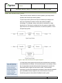
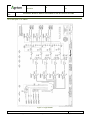
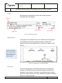
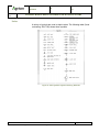
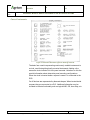
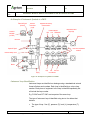
Creation/Revision Date: 2015-08-301 Revision Number: 00 Element Reference: n/a Review Date: 2015-11-01 Site: Functional Area: Functional Group: Subject Area: Vanscoy Surface Operations Training Document Type: Document Sub-Type: Document Category: Document #: Std Operation Equipment Module EM14-1 Manual Document Title: EM14-1 INSTRUMENTATION & CONTROL SYSTEMS EM14-1 Instrumentation & Control Systems Equipment Module Element Owner: Document Owner: Caretaker: Printed: Choose an item. Choose an item. Choose an item. 30/08/2015 8:12 AM Page 1 of 43 If printed, this becomes a copy of a controlled document. This copy is valid for 24 hours ONLY from the time of printing. Revision Date: 2015-08-30 Document Title: Revision Number: Element Reference: 00 n/a EQUIPMENT MODULE - EM14-1 INSTRUMENTATION & CONTROL SYSTEMS TABLE OF CONTENTS Definitions – Generic Instrumentation .................................................................................................... 4 Purpose of this Document ...................................................................................................................... 5 Learning Objectives ............................................................................................................................... 6 Safety .................................................................................................................................................... 7 Hazards and Risks ................................................................................................................................................................... 7 Risk Mitigation.......................................................................................................................................................................... 7 Safety Systems ........................................................................................................................................................................ 7 Instrumentation and Control Basics ....................................................................................................... 8 Sensors .................................................................................................................................................................................... 8 Signals ..................................................................................................................................................................................... 9 Control Loops........................................................................................................................................................................... 9 Open and Closed Loop Control .............................................................................................................................................. 11 Direct/Reverse Acting Control ................................................................................................................................................ 12 On–Off Control ....................................................................................................................................................................... 12 PID Control ............................................................................................................................................................................ 13 Proportional ........................................................................................................................................................................................... 14 Integral .................................................................................................................................................................................................. 15 Derivative .............................................................................................................................................................................................. 15 Tuning ................................................................................................................................................................................................... 15 Cascade Control .................................................................................................................................................................... 16 Ratio Control .......................................................................................................................................................................... 17 Feedforward Control .............................................................................................................................................................. 17 Instrumentation and Control Codes and Standards ............................................................................................................... 18 Measurements Units .............................................................................................................................................................. 19 Standard Signals and Ranges ............................................................................................................................................... 20 Instrumentation Standards, Symbols and Drawings ............................................................................. 21 An Example of a P&ID ........................................................................................................................................................... 22 Who uses P&IDs? .................................................................................................................................................................. 23 Resource Materials for Reading P&IDs ................................................................................................................................. 23 PFD and P&ID Conventions................................................................................................................................................... 24 Footer .................................................................................................................................................................................................... 25 Equipment List ....................................................................................................................................................................................... 25 Connectors ............................................................................................................................................................................................ 25 Piping Line Symbols .............................................................................................................................................................................. 26 Valves.................................................................................................................................................................................................... 27 Instrument Lines .................................................................................................................................................................................... 28 General Instruments .............................................................................................................................................................................. 29 An Example of Instrument Symbols in a P&ID ....................................................................................................................................... 30 Instrument Loop Identification ................................................................................................................................................................ 30 Process Control System (PCS) ............................................................................................................ 33 Distributed Control System .................................................................................................................................................... 33 Printed: 2015-08-30 8:12 AM Page: 2 of 43 If printed, this becomes a copy of a controlled document. This copy is valid for 24 hours ONLY from the time of printing. Revision Date: 2015-08-30 Document Title: Revision Number: Element Reference: 00 n/a EQUIPMENT MODULE - EM14-1 INSTRUMENTATION & CONTROL SYSTEMS Programmable Logic Controllers ............................................................................................................................................ 33 Workstations .......................................................................................................................................................................... 34 Main Control Room (EH&S Building) Stations ........................................................................................................................................ 35 Training Room Stations ......................................................................................................................................................................... 35 Satellite Stations .................................................................................................................................................................................... 35 PCS Architecture and Communications ................................................................................................................................. 36 Vendor Equipment Controls ................................................................................................................................................... 36 System Redundancy .............................................................................................................................................................. 37 Uninterruptible Power Supply (UPS) ...................................................................................................................................... 38 PCS Environmental Control ................................................................................................................................................... 39 Human Machine Interface ...................................................................................................................................................... 39 Automatic versus Manual Operation ...................................................................................................................................... 41 Automatic Sequencing ........................................................................................................................................................................... 41 Automatic Process Control..................................................................................................................................................................... 41 Operators’ Roles .................................................................................................................................................................................... 42 Appendix.............................................................................................................................................. 43 Related Documents ............................................................................................................................................................... 43 Revision History ..................................................................................................................................................................... 43 Printed: 2015-08-30 8:12 AM Page: 3 of 43 If printed, this becomes a copy of a controlled document. This copy is valid for 24 hours ONLY from the time of printing. Revision Date: 2015-08-30 Document Title: Revision Number: Element Reference: 00 n/a EQUIPMENT MODULE - EM14-1 INSTRUMENTATION & CONTROL SYSTEMS Definitions – Generic Instrumentation Term Description DeviceNet DeviceNet is a network system used in the automation industry to interconnect control devices for data exchange. HART Protocol The HART Communications Protocol (Highway Addressable Remote Transducer Protocol) is a digital industrial automation protocol. Its most notable advantage is that it can communicate over legacy 4 to 20 mA analog instrumentation wiring, sharing the pair of wires used by the older system. Due to the huge installed base of 4 to 20 mA systems throughout the world, the HART Protocol is one of the most popular industrial protocols. In 1986, it was made an open protocol. All terms found at: http://www.engineering-dictionary.org Printed: 2015-08-30 8:12 AM Page: 4 of 43 If printed, this becomes a copy of a controlled document. This copy is valid for 24 hours ONLY from the time of printing. Revision Date: 2015-08-30 Document Title: Revision Number: Element Reference: 00 n/a EQUIPMENT MODULE - EM14-1 INSTRUMENTATION & CONTROL SYSTEMS Purpose of this Document The EM14-1 Instrumentation & Control Systems learning module is a key resource created to help operations personnel learn about the systems used to control the process used at Vanscoy Potash Operations. This document contains: Printed: 2015-08-30 8:12 AM Learning outcomes for this module Safety-related information Instrumentation and control basics Instrumentation standards, symbols and drawings Process control systems Troubleshooting Appendices with additional related information. Page: 5 of 43 If printed, this becomes a copy of a controlled document. This copy is valid for 24 hours ONLY from the time of printing. Revision Date: 2015-08-30 Document Title: Revision Number: Element Reference: 00 n/a EQUIPMENT MODULE - EM14-1 INSTRUMENTATION & CONTROL SYSTEMS Learning Objectives On completion of this learning module you will be able to: Printed: 2015-08-30 8:12 AM List and describe the key hazards and risks associated with working on or around the equipment described in this module Identify steps necessary to mitigate risks when working on or around this equipment Describe safety systems that are part of the equipment List the parts of a control loop and describe their functions Describe various control actions in simple terms Describe the two key instrumentation drawings used at VPO Recognize and explain the use of standard instrumentation symbols in drawings List and describe the basic functional parts of process control system Describe operating considerations of instrumentation equipment and systems Describe basic control system troubleshooting techniques for operators Page: 6 of 43 If printed, this becomes a copy of a controlled document. This copy is valid for 24 hours ONLY from the time of printing. Revision Date: 2015-08-30 Document Title: Revision Number: Element Reference: 00 n/a EQUIPMENT MODULE - EM14-1 INSTRUMENTATION & CONTROL SYSTEMS Safety At Vanscoy Potash Operations, employee safety is our top priority. Every employee must be aware of all pertinent workplace safety procedures and do their part to keep themselves and others safe. Hazards and Risks The systems described in this document measure or control some aspect of the process either directly or as part of a larger machine or system. This means personnel may come in contact with process hazards when operating, adjusting or inspecting the system. Note: For additional safety information related to working in plant areas refer to the applicable building, overview and process modules for the area. Risk Mitigation When working on or around this equipment maintain the following safe work practices: Read the manual before working with any of the products described in this document. Always follow standard operating procedures when operating or maintaining this equipment. Grounding to protect against electric shock Failsafe configurations in instruments and equipment that protect personnel in the event of equipment failure Radiation warning signs for nuclear devices All devices must comply with Hazardous Area Certification Safety Systems Printed: 2015-08-30 8:12 AM Page: 7 of 43 If printed, this becomes a copy of a controlled document. This copy is valid for 24 hours ONLY from the time of printing. Revision Date: 2015-08-30 Document Title: Revision Number: Element Reference: 00 n/a EQUIPMENT MODULE - EM14-1 INSTRUMENTATION & CONTROL SYSTEMS Instrumentation and Control Basics Instrumentation is defined as the art and science of measurement and control of process variables within a production or manufacturing area. Measurement systems may be as simple as direct reading thermometers or may be as complex as multi-variable process analyzers. A control system is a device, or set of devices, that manages, commands, directs, or regulates the behavior of other devices or systems. Control systems typically are made up of multiple devices working together to detect, communicate, indicate and control one or more processes. Process control systems typically include sensors, transmitters, communications media, signal interfaces (I/O), controllers (or control systems), signal converters, and actuators/final control elements (FCE). Control systems are typically made up of multiple control loops, each monitoring and controlling different parameters. Systems may implement open or closed loop control. Control algorithms determine how control systems respond to measurement changes. Sensors Tips and Techniques: Most sensors are not accessible to the operator. However, you can monitor the physical condition of the sensor housings, transmitters and cabling and report any damage or deterioration. Also, if the indications produced by sensors appear incorrect, or erratic, report this to your supervisor, Central Control and/or maintenance. Printed: 2015-08-30 8:12 AM Sensors detect real world physical parameters. Real world parameters that exist in two possible states (on/off) are called discretes. A typical example is a switch opening and closing. Parameters that vary continuously through a range, such as flow, temperature, level, distance, angle, pressure, etc. are called analog or continuous parameters. Analog sensors typically produce low-level output signals (electrical or pneumatic in most industrial applications) that vary over a known range of values. Typically analog sensors are connected to transmitters. A transmitter is a device that takes a small signal, conditions it, amplifies it, standardizes its range, and sends it along to the next segment of the control system as a standard signal. Page: 8 of 43 If printed, this becomes a copy of a controlled document. This copy is valid for 24 hours ONLY from the time of printing. Revision Date: 2015-08-30 Document Title: Revision Number: Element Reference: 00 n/a EQUIPMENT MODULE - EM14-1 INSTRUMENTATION & CONTROL SYSTEMS Signals Discrete signals may be sent to indicators such as panel indicator lights, to show the status of some aspect of the process. Older, analog instrumentation systems (many of which still exist) used Tips and Techniques: Calibration, maintenance and repair of instrumentation systems is the responsibility of the instrument maintenance personnel. However, a basic understanding of instrumentation systems will assist the operator in recognizing problems and working with the instrumentation and other personnel in solving problems. analog signals represented by pneumatic pressure (3 to 15 psi), electrical current (4 to 20 mA), or (less often) voltage or signal frequency. In a simple system analog signals may be sent to a gauge or meter to indicate a range of values. In more complex systems analog signals are sent to a controller, which is used to control some aspect of the process. Modern instrumentation and control systems typically convert signals from analog to digital data so the information is compatible with computer systems. The point in the system where analog to digital (A/D) conversion takes place may vary depending on the vintage and complexity of the system. There are also hybrid systems that combine analog and digital signals in the same communications link (e.g. HART protocol). Discrete, analog and digital signals can be sent to a programmable logic controller (PLC), digital control system (DCS), supervisory control and data acquisition (SCADA) system, or other type of computerized controller. Any needed signal conditioning or conversion is done as the signal enters the system. Once in digital format, the data can be displayed, stored, or manipulated for control purposes. Control Loops A measurement signal in a control system is usually referred to as the process variable, or PV. The PV is typically sent to a controller, which is a device that attempts to maintain consistent control of the process. The controller compares the PV with a setpoint (SP). The setpoint is the value at which the controller will try to maintain the PV. (When everything is working properly they should be same value.) The controller uses a control algorithm (program) that responds to differences (errors) between the PV and SP and creates an output (OP) signal. Printed: 2015-08-30 8:12 AM Page: 9 of 43 If printed, this becomes a copy of a controlled document. This copy is valid for 24 hours ONLY from the time of printing. Revision Date: 2015-08-30 Document Title: Revision Number: Element Reference: 00 n/a EQUIPMENT MODULE - EM14-1 INSTRUMENTATION & CONTROL SYSTEMS Pneumatic signal (3 to 15 psi) Actuator (valve positioner) Signal Converter (current to pressure - aka I/P) Electric signal (4 to 20 mA current) Final Control Element (valve) OP SP Tips and Techniques: Controller (level) Electric signal (4 to 20 mA current) PV Operators who can read plant drawings and relate them to actual systems in the plant can operate those systems more effectively. They can also provide valuable assistance to maintenance personnel. Transmitter (level) Sensor (level) Figure 1. A typical analog control loop The output signal is used to operate a final control element (solenoids, valves, regulators, circuit breakers, relays, indicators, variable frequency drive / motor, or other actuator). In response to the output signal, the final control element manipulates the process (flow, temperature, pressure, etc.). Often this is the same parameter measured by the sensor, (or it may be another parameter, which affects the parameter measured by the sensor). This completes the loop, allowing the control system to ensure the process is controlled to the value specified by the setpoint. Controllers may be standalone controllers, or part of a digital control system. Printed: 2015-08-30 8:12 AM Page: 10 of 43 If printed, this becomes a copy of a controlled document. This copy is valid for 24 hours ONLY from the time of printing. Revision Date: 2015-08-30 Document Title: Revision Number: Element Reference: 00 n/a EQUIPMENT MODULE - EM14-1 INSTRUMENTATION & CONTROL SYSTEMS Open and Closed Loop Control There are two common classes of control systems: open loop control systems and closed loop control systems. In open loop control systems an output is initiated by a change in an input, but no attempt is made to monitor the results and adjust accordingly. For example, when a wall switch is switched on, a light should turn on. But there is nothing built into the system to detect if the light did not turn on and take some action to correct the problem. This is an open loop system. Figure 2. Open and closed loop control system diagrams Tips and Techniques: Most control loops in the plant are closed loop and should be operated in Automatic to ensure the most effective and efficient operation. Ultimately, operation in Automatic mode will make the operator’s activities easier. Printed: 2015-08-30 8:12 AM In closed loop control systems the results are monitored and corrections are made based on feedback. A furnace thermostat is an example. When the air temperature around the thermostat drops below its setpoint the thermostat sends a signal to the furnace to start. The thermostat continues to monitor the temperature and when it rises above the setpoint (plus a deadband value) a signal is sent to the furnace to turn off. A closed loop system is also called a feedback control system. Page: 11 of 43 If printed, this becomes a copy of a controlled document. This copy is valid for 24 hours ONLY from the time of printing. Revision Date: 2015-08-30 Document Title: Revision Number: Element Reference: 00 n/a EQUIPMENT MODULE - EM14-1 INSTRUMENTATION & CONTROL SYSTEMS Closed loop control systems can range from simple to complex. Simple on/off or on/off with deadband (as described) relies on discrete sensors and actuators. More complex control systems monitor continuous signals and provide continuous outputs. Direct/Reverse Acting Control Controllers change their output (to the final control element) in response to measurement changes (PV). In some cases the controller output signal must act opposite to the input change. For example, in a temperature control system, if temperature increases, the controller may have to decrease the amount of fuel to a burner to bring the temperature back to setpoint. In this case when temperature increases, fuel flow must decrease. This is called reverse acting. If the system used a cooling system to control temperature, when temperature increases, coolant flow must increase. This is direct acting. On–Off Control The thermostat control system previously described is an example of a simple on/off feedback controller. Initially the temperature is below the setpoint and the heater is on. When the temperature (PV) increases past the temperature setpoint (SP), a switch opens, switching off the heater. In this type of on/off control, to ensure that the thermostat does not cycle on and off frequently, deadband (often also called hysteresis) is incorporated into the controller. As the temperature decreases, it must go past the setpoint. It only turns on the heater when it reaches the turn-on point. The range of values between the turn-on and turn-off points is called the deadband. The width of deadband may be adjustable or programmable. This is a relatively crude level of control and is often not adequate for industrial control systems. Printed: 2015-08-30 8:12 AM Page: 12 of 43 If printed, this becomes a copy of a controlled document. This copy is valid for 24 hours ONLY from the time of printing. Revision Date: 2015-08-30 Document Title: Revision Number: Element Reference: 00 n/a EQUIPMENT MODULE - EM14-1 INSTRUMENTATION & CONTROL SYSTEMS Figure 3. On–Off Control PID Control Tips and Techniques: PID control only functions when a system is set to Automatic mode. Printed: 2015-08-30 8:12 AM A PID controller calculates an error value as the difference between a measured process variable and a desired setpoint. The controller attempts to minimize the error by adjusting the process control outputs. The PID controller algorithm involves three separate parameters, and is accordingly sometimes called three-term control. These are: Proportional (P) – also often expressed in terms of Gain Integral (I) – also known as Reset Derivative (D) – also known as Rate Page: 13 of 43 If printed, this becomes a copy of a controlled document. This copy is valid for 24 hours ONLY from the time of printing. Revision Date: 2015-08-30 Document Title: Revision Number: Element Reference: 00 n/a EQUIPMENT MODULE - EM14-1 INSTRUMENTATION & CONTROL SYSTEMS Figure 4. PID Control Proportional When a controller implements proportional control it compares the setpoint value with the measurement value and produces an output value proportional to the difference. By configuring the controller the magnitude of the output can be set. For example, if the difference is 10% of the measurement range, the controller can be set to change its output 10%, 20%, etc. in response. The amount the controller’s output is set to change is called its proportional band. Note: Proportional Band is expressed in %, Gain is expressed as a multiplier. %PB = 100/Gain so A Proportional Band of 100% is a Gain of 1. A Proportional Band of 50% is a Gain of 2, etc. Printed: 2015-08-30 8:12 AM Page: 14 of 43 If printed, this becomes a copy of a controlled document. This copy is valid for 24 hours ONLY from the time of printing. Revision Date: 2015-08-30 Document Title: Revision Number: Element Reference: 00 n/a EQUIPMENT MODULE - EM14-1 INSTRUMENTATION & CONTROL SYSTEMS Integral Integral control is used to augment proportional control. Integral control action responds by increasing the output (ramping) at a rate configured into the controller. In response to the error (difference between the PV and SP), the controller increases its output (ramps) by a set amount per unit time. As the output changes, the process changes, causing the measurement to change, this in turn causes the error to become smaller. Eventually the difference becomes zero, which is the goal of the controller. Note: Integral is expressed in terms of number of seconds per Repeat, or Repeats per second, depending on the equipment manufacturer. A “Reset” is defined as the amount the controller output will change in a second for a given error (PV-SP) with a given Gain setting. Derivative Derivative control responds to how quickly the measurement (PV) is changing. If the rate of change is large, the controller makes a larger change to the output. This brings the PV back to setpoint more quickly, ensuring that quick measurement changes do not affect the process significantly. Derivative control is typically used in temperature control systems where an external event (e.g. introduction of wet feed into a dryer) will change the temperature quickly. When a fast change is detected, the control causes a large amount of heat to be added quickly to bring the temperature back into line before it changes too much. Note: Derivative, or Rate, is expressed in terms of time—usually seconds, but sometimes in minutes. Tuning Tips and Techniques: Sometimes tuning a control loop can take time and experimentation. Don’t give up too soon and revert to operating a system in Manual. Printed: 2015-08-30 8:12 AM Most analog control systems employ proportional and integral control; some also implement derivative. For best results a controller must be “tuned”. Tuning is the process of adjusting the amount of each parameter to get optimal results from the process it is on. Many factors can affect loop tuning. Loop tuning is typically done by a process engineer and, once completed, is not changed by the operator. Page: 15 of 43 If printed, this becomes a copy of a controlled document. This copy is valid for 24 hours ONLY from the time of printing. Revision Date: 2015-08-30 Document Title: Revision Number: Element Reference: 00 n/a EQUIPMENT MODULE - EM14-1 INSTRUMENTATION & CONTROL SYSTEMS Cascade Control In some situations the desired setpoint of a loop may need to change in response to other plant parameters. For example, when the plant is processing ore at a specific rate (tonnage), some other systems may have to operate at a rate based on the tonnage. If the tonnage is increased, the other systems must increase proportionately. If plant feed rate is controlled by one loop, the output of that loop can be used as the setpoint for one or more other control loops. As tonnage increases, the setpoint to the other loops increase. In the following example the plant feed rate is controlled by the feeder on the bottom of the fine ore bin (not shown). As feed out of the bin increases the level in the bin will start to decrease. The bin level controller will increase its output, which increases the setpoint of the control loop that controls the ore feeder. This will ensure that the ore feeder operates at a rate that can keep the fine ore bin level constant. Figure 5. Example of cascade control at VPO Note: For information on an example of cascade control used in the mill, see PM10-4 Crushing Circuit process module Operation and Control section. Printed: 2015-08-30 8:12 AM Page: 16 of 43 If printed, this becomes a copy of a controlled document. This copy is valid for 24 hours ONLY from the time of printing. Revision Date: 2015-08-30 Document Title: Revision Number: Element Reference: 00 n/a EQUIPMENT MODULE - EM14-1 INSTRUMENTATION & CONTROL SYSTEMS Ratio Control A ratio controller accepts two different instrumentation signals and provides an output based on an operator-set ratio between the two. For example, in a mixing system where two different materials must be mixed in a fixed ratio the flow rates of both feeds can be measured and one controlled to ensure it flows at the correct rate to achieve the mix ratio. One example of ratio control as it is used at VPO is reagent mixing control loops. Reagents added to the flotation circuit must be added at a rate based on the mill feed rate. The “wild feed” flow measurement shown in the following diagram would be the mill feed rate. The “controlled feed” flow measurement shown would be the reagent flow rate. The reagent flow rate would be adjusted to track the mill feed based on a preset ratio. Note: Typically the PCS allows the operator to adjust the ratio on the HMI within a preset range of values. Figure 6. Ratio Control Feedforward Control Feedforward control is a technique that detects disturbances in a control system before they have a chance to affect the output of the process. Usually feedforward is combined with feedback control. The following Printed: 2015-08-30 8:12 AM Page: 17 of 43 If printed, this becomes a copy of a controlled document. This copy is valid for 24 hours ONLY from the time of printing. Revision Date: 2015-08-30 Document Title: Revision Number: Element Reference: 00 n/a EQUIPMENT MODULE - EM14-1 INSTRUMENTATION & CONTROL SYSTEMS diagram shows a heat exchanger, a typical application for feedforward control. Tips and Techniques: Advanced control techniques can appear complicated at first, but they do work. Be patient…you didn’t learn everything about operating your smart phone the first day you had it. Figure 7. Feedforward control In this example the flowrate of the process input to the heat exchanger is monitored, as well as the output of the exchanger. If the flowrate of the incoming fluid increases significantly, it will cause a decrease in return temperature, which feedback then has to react to. By monitoring the supply flow events that might result in a system upset can be detected and reacted to before they affect the return temperature. Instrumentation and Control Codes and Standards The specifications, codes and standards that govern the installation, operation and maintenance of control systems are defined by a multitude of organizations. Since this document primarily focuses on operations personnel, only a few key organizations will be mentioned here. Probably the two key organizations that dictate how control systems are designed, built and documented are: ISA International Society of Automation IEEE Institute of Electrical & Electronic Engineer Canadian organizations that play a part in control systems include: Printed: 2015-08-30 8:12 AM CSA Canadian Standards Association Page: 18 of 43 If printed, this becomes a copy of a controlled document. This copy is valid for 24 hours ONLY from the time of printing. Revision Date: 2015-08-30 Document Title: Revision Number: Element Reference: 00 n/a EQUIPMENT MODULE - EM14-1 INSTRUMENTATION & CONTROL SYSTEMS CEC Canadian Electrical Code Significant international organizations include: IEC International Electrotechnical Commission ISO International Organization for Standardization Related provincial organizations include: SEA Saskatchewan Electrical Authority SWCB Saskatchewan Workers Compensation Board SMR Saskatchewan Mines Regulations Important safety-related organizations include: MSHA Mine Safety and Health Administration, CFR 30, Subchapter N and Part 56/57 of the Mine Health and Safety Standards OH&S Saskatchewan Occupational Health and Safety.(OH&S Act, 1993, OH&S Regulations 1996) MSC Nuclear Safety Association Measurements Units Agrium’s standards indicate that personnel should use metric units in (based on the International System of Units (SI)) for instrumentation and control applications. A list of standard units follows: Measured Parameter Units of Measure(SI) Concentration parts per million (ppm) Conductance Siemens (μS) Density kilograms per cubic metre (kg/m3) Electrical Current Amperes (A), milliamps (mA) Energy Joule (J), Kilowatt-hours (kWh) Flow (mass) tonnes per hour(t/h), kilograms per hour (kg/h) Flow (volumetric) Litres per minute (l/min) Frequency Hertz (Hz) Level Percentage (%) of full Mass kilograms (kg), tonne (t) Power Consumption Watt (W), kilowatt (kW) Printed: 2015-08-30 8:12 AM Page: 19 of 43 If printed, this becomes a copy of a controlled document. This copy is valid for 24 hours ONLY from the time of printing. Revision Date: 2015-08-30 Document Title: Revision Number: Element Reference: 00 n/a EQUIPMENT MODULE - EM14-1 INSTRUMENTATION & CONTROL SYSTEMS Measured Parameter Units of Measure(SI) Pressure kiloPascal (kPa) Speed (Velocity) metre per second (m/s) Sound Pressure Level decibels “A” scale weighted (dBA) Temperature degree Celsius (ºC) Turbidity Nephelometric Turbidity Units (NTU) Viscosity Pascal-second (Pa-s), 1 mPa-s = 1cP Voltage (alternating & direct) Volts (VAC, VDC) Vibration Inches per second (in/sec) or cycles/sec (cps). Standard Signals and Ranges Information regarding control signals, power, and air are included in this section: Controlled Parameter Measure Local pneumatic control 20 - 100 kPa(g) Plant air supply pressure 550 - 760 kPa(g) Instrument air supply pressure (-40°C dew point) 550 - 760 kPa(g) DCS (Distributed Control System), analog electronic input/output signals (isolated) 4 - 20 mA DC c/w HART Protocol UPS (Uninterruptable 120 VAC, 60 Hz PLC (Programmable Logic Controller), control voltage for motor starters and related controls 120 VAC, 60 Hz PLC (Programmable Logic Controller), discrete electric input signals (isolated) 120 VAC, 60 Hz PLC (Programmable Logic Controller), discrete electric output signals (dry contact) 120 VAC, 60 Hz Solenoid valve control 120 VAC, 60 Hz Printed: 2015-08-30 8:12 AM Page: 20 of 43 If printed, this becomes a copy of a controlled document. This copy is valid for 24 hours ONLY from the time of printing. Revision Date: 2015-08-30 Document Title: Revision Number: Element Reference: 00 n/a EQUIPMENT MODULE - EM14-1 INSTRUMENTATION & CONTROL SYSTEMS Instrumentation Standards, Symbols and Drawings There are two key types of drawings used to show how the equipment and instrumentation in process plants are connected as systems. These are: Tips and Techniques: Operators who can read plant drawings and relate them to actual systems in the plant can operate those systems more effectively. They can also provide valuable assistance to maintenance personnel. Process flow diagrams (PFD) Piping and instrument diagrams (P&ID). PFDs show process equipment and how it is interconnected by piping and other conveyances. The simplicity of these diagrams makes them useful in understanding the overall flow of materials through the process, including how equipment is interconnected. P&IDs show similar information to that shown in PFDs but also include information about instrumentation and controls, and how they are connected together and to supervisory control systems. This makes P&IDs more complex, but they provide more information. A typical process plant requires many diagrams. Each captures some area or process in detail. Standard symbols are used. The organization that sets the standards for symbols, identifiers, and terminology is the International Society of Automation (ISA). Note: The International Society of Automation (ISA) is a non-profit technical society for engineers, technicians, businesspeople, educators and students, who work, study or are interested in industrial automation and pursuits related to it, such as instrumentation. It was originally known as the Instrument Society of America (ISA), and the society's scope now includes many technical and engineering disciplines. Printed: 2015-08-30 8:12 AM Page: 21 of 43 If printed, this becomes a copy of a controlled document. This copy is valid for 24 hours ONLY from the time of printing. Revision Date: 2015-08-30 Document Title: Revision Number: Element Reference: 00 n/a EQUIPMENT MODULE - EM14-1 INSTRUMENTATION & CONTROL SYSTEMS An Example of a P&ID Figure 8. A typical P&ID Printed: 2015-08-30 8:12 AM Page: 22 of 43 If printed, this becomes a copy of a controlled document. This copy is valid for 24 hours ONLY from the time of printing. Revision Date: 2015-08-30 Document Title: Revision Number: Element Reference: 00 n/a EQUIPMENT MODULE - EM14-1 INSTRUMENTATION & CONTROL SYSTEMS Who uses P&IDs? Tips and Techniques: PFDs and P&IDs look complicated. This can be intimidating at first. Break the diagram down into pieces. Look for symbols you can identify, numbers you recognize and labels you are familiar with. Then work from there. Keep this document handy for reference. P&IDs can be your best friend when figuring out what is going on in a plant system. Process diagrams are used by many technical personnel in one way or another. Process engineers use process flow diagrams and symbols during the design process to map the flow of the process and equipment used in it. Control and automation engineers use PFDs during the process of designing instrumentation and control systems. They produce the P&IDs, using standard instrumentation and measurement symbols to label instrument loop diagrams. Maintenance personnel use PFDs and P&IDs in planning and executing preventative and reactive maintenance activities, including planning or verifying lockout procedures. Technical writers use PFDs and P&IDs during the creation of procedures, checklists and training materials. Operators use P&IDs to understand the processes they operate, and to use the procedures/best practices they employ to operate their areas effectively. Resource Materials for Reading P&IDs A library of PFDs, P&IDs and other engineering resource materials is available to VPO personnel on the ADOM document management system. Included in this library are several documents that provide a key to the symbols and conventions used on PFDs and P&IDs. These documents are listed in the following table and in the Related Documents section at the end of this manual. File Name Description Contents 100J7745 P&ID Symbols Sheet 1 of 5 Piping line symbols Valve symbols Normally closed valve symbols Insulation and tracing symbols ON/OFF page connector symbols Pipe identification symbols Valve identification symbols Pipe material identification symbols Equipment identification symbols Fluid service code symbols Piping components symbols Tips and Techniques: Get your supervisor to print out a copy of these sheets and keep them somewhere that you can find them. Refer to them when you need to. They will prove invaluable when learning to read P&IDs. Printed: 2015-08-30 8:12 AM Page: 23 of 43 If printed, this becomes a copy of a controlled document. This copy is valid for 24 hours ONLY from the time of printing. Revision Date: 2015-08-30 Document Title: Revision Number: Element Reference: 00 n/a EQUIPMENT MODULE - EM14-1 INSTRUMENTATION & CONTROL SYSTEMS 100J7746 P&ID Symbols Sheet 2 of 5 Miscellaneous/specialty equipment symbols Pump symbols Mixer symbols Vessel symbols Driver symbols Blower symbols Compressor symbols Process unit symbols 100J7747 P&ID Symbols Sheet 3 of 5 Instrument identification General electrical control symbols Miscellaneous instrumentation Instrument identification letters Instrument line symbols Instrument abbreviations General instrument symbols Control valve symbols Primary element flow instrument symbols 100J7748 P&ID Symbols Sheet 4 of 5 Material handling equipment symbols 100J7749 P&ID Symbols Sheet 5 of 5 HVAC symbols HVAC abbreviations Fire suppression abbreviations and symbols Motor control types DCS HMI displayed PLC HMI displayed PFD and P&ID Conventions PFDs and P&IDs are drawn to standards that all personnel can understand. The drawing typically show flow from left to right, top to bottom. Equipment, process lines and signals, instrumentation and other information is show using standard symbols. Printed: 2015-08-30 8:12 AM Page: 24 of 43 If printed, this becomes a copy of a controlled document. This copy is valid for 24 hours ONLY from the time of printing. Revision Date: 2015-08-30 Document Title: Revision Number: Element Reference: 00 n/a EQUIPMENT MODULE - EM14-1 INSTRUMENTATION & CONTROL SYSTEMS Footer All drawings are formatted with a footer that contains important information about the diagram: Plant Area Drawing name Drawing number Revision number Figure 9. P&ID drawing footer Equipment List The equipment list located at the top of the P&ID lists all the equipment on the diagram and includes equipment numbers. Typically the equipment name/number appears above the location it appears on the drawing. Tips and Techniques: Learn the names of each piece of equipment. None of us can afford to make a mistake caused by a misunderstanding. Figure 10. Equipment list at top of the P&ID Connectors On the left and right sides of the P&ID, pointed boxes containing the numbers of other P&IDs show the inputs and outputs to and from the equipment on the drawing. Typically a note describes where the inputs come from and the outputs go to. Often, additional information about pipe sizes, etc. is included as well. Printed: 2015-08-30 8:12 AM Page: 25 of 43 If printed, this becomes a copy of a controlled document. This copy is valid for 24 hours ONLY from the time of printing. Revision Date: 2015-08-30 Document Title: Revision Number: Element Reference: 00 n/a EQUIPMENT MODULE - EM14-1 INSTRUMENTATION & CONTROL SYSTEMS Figure 11. Inputs and outputs on P&IDs Piping Line Symbols Piping is shown on P&IDs using several different styles and weights of lines. Additional information about lines is included in text labels adjacent to the line. Figure 12. Piping Line Symbol legend on drawing 100J7745 Note: These lines never represent electrical lines. Printed: 2015-08-30 8:12 AM Page: 26 of 43 If printed, this becomes a copy of a controlled document. This copy is valid for 24 hours ONLY from the time of printing. Revision Date: 2015-08-30 Document Title: Revision Number: Element Reference: 00 n/a EQUIPMENT MODULE - EM14-1 INSTRUMENTATION & CONTROL SYSTEMS Valves A variety of symbols are used to depict valves. The following table (found on drawing 100J7745) shows these symbols. Figure 13. Valve symbols legend on drawing 100J7745 Printed: 2015-08-30 8:12 AM Page: 27 of 43 If printed, this becomes a copy of a controlled document. This copy is valid for 24 hours ONLY from the time of printing. Revision Date: 2015-08-30 Document Title: Revision Number: Element Reference: 00 n/a EQUIPMENT MODULE - EM14-1 INSTRUMENTATION & CONTROL SYSTEMS Instrument Lines Figure 14. Instrument lines legend on drawing 100J7747 Printed: 2015-08-30 8:12 AM Page: 28 of 43 If printed, this becomes a copy of a controlled document. This copy is valid for 24 hours ONLY from the time of printing. Revision Date: 2015-08-30 Document Title: Revision Number: Element Reference: 00 n/a EQUIPMENT MODULE - EM14-1 INSTRUMENTATION & CONTROL SYSTEMS General Instruments Figure 15. General Instruments legend on drawing 100J7747 The basic form used in representing continuously variable instruments is a circle, used for depicting locally mounted instruments. Adding a line across the circle indicates it is front panel mounted. Variations on this line provide information about alternative panel mounting configurations. When the circle is located inside a square it means it is connected to the DCS. On-off devices are represented by diamond shapes. When located inside a square they are connected to a PLC. Additional information may be included to indicate functionality such as logical AND, OR, time delay, etc. Printed: 2015-08-30 8:12 AM Page: 29 of 43 If printed, this becomes a copy of a controlled document. This copy is valid for 24 hours ONLY from the time of printing. Revision Date: 2015-08-30 Document Title: Revision Number: Element Reference: 00 n/a EQUIPMENT MODULE - EM14-1 INSTRUMENTATION & CONTROL SYSTEMS An Example of Instrument Symbols in a P&ID Electrical Signal (4-20mA) Pressure Transmitter (Local) Equipment serviced by instrumentation Pressure alarms High Low Differential Pressure Indication (on DCS) Temperature alarm High-High Interlock Ball Valve Hydraulic Signal Level and Temperature switches. Pressure Safety Valve Motors High Piping Low Low-Low Level alarms Figure 16. Examples of symbols on a P&ID Instrument Loop Identification Instrument loops are identified on drawings using a standardized set and format of letters and numbers. Each loop is identified by a unique loop number. Each piece of equipment in the loop is identified separately but all include the loop number E.g. PI 2047 and PIT 2047 are two parts of the same loop. The type of instrument loop is identified using two to four letters that indicate: Printed: 2015-08-30 8:12 AM The type of loop: flow (F), pressure (P), level (L), temperature (T), etc. Page: 30 of 43 If printed, this becomes a copy of a controlled document. This copy is valid for 24 hours ONLY from the time of printing. Revision Date: 2015-08-30 Document Title: Revision Number: Element Reference: 00 n/a EQUIPMENT MODULE - EM14-1 INSTRUMENTATION & CONTROL SYSTEMS Tips and Techniques: It’s helpful to learn these numbering conventions. You will see them on the HMI displays. Printed: 2015-08-30 8:12 AM The type of equipment: element (E), transmitter (T), valve (V), alarm (A), controller (C), etc. Whether the loop includes an indication (I) So flow loop may have all of the following: A flow element - e.g. FE 2533 A flow transmitter – e.g. FT 2533 A flow controller with indicator – e.g. FIT 2533 A flow control valve – e.g. FV 2533 Page: 31 of 43 If printed, this becomes a copy of a controlled document. This copy is valid for 24 hours ONLY from the time of printing. Revision Date: 2015-08-30 Document Title: Revision Number: Element Reference: 00 n/a EQUIPMENT MODULE - EM14-1 INSTRUMENTATION & CONTROL SYSTEMS The following table (from 100J7747 provides a list of standard instrument identification letters: Figure 17. Instrument identification number Printed: 2015-08-30 8:12 AM Page: 32 of 43 If printed, this becomes a copy of a controlled document. This copy is valid for 24 hours ONLY from the time of printing. Revision Date: 2015-08-30 Document Title: Revision Number: Element Reference: 00 n/a EQUIPMENT MODULE - EM14-1 INSTRUMENTATION & CONTROL SYSTEMS Process Control System (PCS) Most plant processes are monitored and controlled by the process control system (PCS). The PCS is made up of the distributed control system (DCS), local programmable logic controllers (PLC) and workstations that display the human machine interface (HMI). PCS HMI Inputs Inputs DCS PLC Outputs Outputs Figure 18. Block diagram of the PCS Distributed Control System The distributed control system is an industrial network that consists of industrial computers, communications media and other devices. Field devices (sensors, transmitters, signal converters, etc.) connect into the DCS input/output (I/O). The DCS converts the signals to digital form which is used by the system’s industrial computer, which runs control software. The control software provides the functionality of controllers, historians and other devices. Programmable Logic Controllers Programmable logic controllers are digital computers used for automation of electromechanical processes. They accept discrete and analog signals and control equipment such as fixed-speed motors and other electrical loads. Typically PLCs perform control functions using programs (often in the form of ladder logic). Printed: 2015-08-30 8:12 AM Page: 33 of 43 If printed, this becomes a copy of a controlled document. This copy is valid for 24 hours ONLY from the time of printing. Revision Date: 2015-08-30 Document Title: Revision Number: Element Reference: 00 n/a EQUIPMENT MODULE - EM14-1 INSTRUMENTATION & CONTROL SYSTEMS Tips and Techniques: You may never see the actual computers or PLCs that make up the process control system, but understanding how they work together will help you operate—especially if exceptional situations. E.g. if a piece of equipment fails, or if communications is lost. Figure 19. A PLC panel in a switchroom PLCs are often modular and can be customized to accept the number and types of inputs and outputs needed. PLCs are typically located in switchrooms, which are located in various plant areas. They communicate digitally with the DCS to receive and share data with the larger system. In some applications PLCs may be equipped to control analog loops, employing PID control. (E.g. PLCs at the Reclaim Brine Pumphouse incorporate analog control loops.) Workstations Workstations are individual computer systems (PCs)—including computer, keyboard, mouse, video monitor, etc.—that are connected to the PCS via a network. Workstations run the human machine interface (HMI) software and display HMI windows that enable operators to monitor and control the process. Printed: 2015-08-30 8:12 AM Page: 34 of 43 If printed, this becomes a copy of a controlled document. This copy is valid for 24 hours ONLY from the time of printing. Revision Date: 2015-08-30 Document Title: Revision Number: Element Reference: 00 n/a EQUIPMENT MODULE - EM14-1 INSTRUMENTATION & CONTROL SYSTEMS Figure 20. Control Room Workstation Displays Main Control Room (EH&S Building) Stations The main control room (Central Control) contains multiple operator workstations that display the HMI. Training Room Stations The Training Room contains one single-seat operator training simulator (OTS) system complete with all operating software, packages and licenses installed. Satellite Stations Tips and Techniques: Being able to operate equipment from the HMI is an important skill whether you are communicating with Central Control or monitoring/operating systems from remote workstations. Printed: 2015-08-30 8:12 AM The Compaction control room contains one quadruple screen operator workstation for Compactors 4 and 5. The room is environmentally controlled. This is a full-application workstation (AW) capable of controlling selected areas, displaying and annunciating alarms and viewing the rest of the operating plant areas. The workstation has all required operating software packages and licenses installed. The Deslime/Flotation area has one dual-screen remote operator workstation located in an environmentally controlled room. This station will allow the field operator from either area to control his area of responsibility, manipulating operating setpoints and basic control for his Page: 35 of 43 If printed, this becomes a copy of a controlled document. This copy is valid for 24 hours ONLY from the time of printing. Revision Date: 2015-08-30 Document Title: Revision Number: Element Reference: 00 n/a EQUIPMENT MODULE - EM14-1 INSTRUMENTATION & CONTROL SYSTEMS unit as required. This workstation has all required operating software packages and licenses installed. Loadout has one single screen operator station for the area. It includes a computer system in a hardened enclosure, including filters and fans, with mouse and keyboard/keypad suitable for rugged use in an industrial environment. PCS Architecture and Communications Tips and Techniques: Fibre-optic cable is not susceptible to electrical noise. PLCs and the DCSs communicate by sending and receiving digital information via Ethernet TCP/IP communication protocol over network cables. Backbone communication (main communications trunks) is via single-mode fibre-optic cable. (See the Related Document section for Process Control System overview and Architecture Block Diagram 334562-0000-48DD-7100.) Sub-systems are linked to the PCS via Ethernet/IP or DeviceNet communication protocols. BACnet/IP to Ethernet/IP protocol converters are used in some cases to interface with fire alarm or building automation systems. In select cases, Modbus communication protocol is used to interface with vendor equipment control packages. Where a control system is not supplied with a vendor package, instrument signals are hard-wired directly to the plant PCS. Vendor Equipment Controls Some turnkey equipment comes from the manufacturer with integrated control systems. Examples include: Printed: 2015-08-30 8:12 AM the controls on compressor air systems and air dryers Page: 36 of 43 If printed, this becomes a copy of a controlled document. This copy is valid for 24 hours ONLY from the time of printing. Revision Date: 2015-08-30 Document Title: Revision Number: Element Reference: 00 n/a EQUIPMENT MODULE - EM14-1 INSTRUMENTATION & CONTROL SYSTEMS Figure 21. A typical vendor control panel primary scrubber feed tank grizzly controls Figure 22. Grizzly screen deck operator control panel Vendor controls are built specifically for their application and tend to have unique user interfaces and operating features. In some cases they provide communications interfaces that allow limited information and control via VPO’s distributed control system. System Redundancy To ensure that important functions continue to operate in the event of a failure in the PCS the following portions of the system are redundant: Printed: 2015-08-30 8:12 AM Page: 37 of 43 If printed, this becomes a copy of a controlled document. This copy is valid for 24 hours ONLY from the time of printing. Revision Date: 2015-08-30 Document Title: Revision Number: Element Reference: 00 n/a EQUIPMENT MODULE - EM14-1 INSTRUMENTATION & CONTROL SYSTEMS Process control network communications, including cabling and electronics Most DCS process controllers Cabinet power supplies The following portions of the system are not redundant: Communications between the PLCs and the PCS network Most PLC process controllers Uninterruptible Power Supply (UPS) Figure 23. Uninterruptible Power Supply A UPS protects sensitive electronic equipment from the most common power problems, including power failures, power sags, power surges, brownouts, line noise, high voltage spikes, frequency variations, switching transients, and harmonic distortion. Printed: 2015-08-30 8:12 AM Page: 38 of 43 If printed, this becomes a copy of a controlled document. This copy is valid for 24 hours ONLY from the time of printing. Revision Date: 2015-08-30 Document Title: Revision Number: Element Reference: 00 n/a EQUIPMENT MODULE - EM14-1 INSTRUMENTATION & CONTROL SYSTEMS PCS Environmental Control Tips and Techniques: Computer systems can fail if their environment is too hot. You can prevent costly production losses by maintaining awareness of whether HVAC systems are working properly. PCS equipment must be maintained in a clean, temperature-controlled environment to ensure continuous, reliable operation. This is accomplished by dedicated HVAC systems for the PCS equipment. Programmable controllers are used to control the blower, cooling, heating, and mixing economizers that are part of this system. These are known as HVAC controls. The HVAC controller can be configured to control one or two independent control processes at the same time. This is managed by BACnet. (BACnet is a data communication protocol for Building Automation and Control Networks.) Human Machine Interface Tips and Techniques: Using the proper terminology when referring to the HMI can prevent misunderstanding. If you refer to a “screen” are you talking about a computer monitor? Is the information shown on a computer monitor? Could the person you are talking to think you are referring a piece of production equipment that sort different sized product? Use the words “process display” and “overlay” when referring to information on the HMI. Printed: 2015-08-30 8:12 AM Each process area has one or more process displays (a full-screen window) on the HMI. Sometimes these displays are also called “pages” or “screens”. Process displays include graphics of equipment (bins, conveyors, compressors, valves, etc.) and status indications (on, off, mode, trips, flow, temperature, etc.). Operators control equipment by clicking graphic representations of the equipment on the screen. Typically, this opens an overlay (a smaller window, sometimes called a popup) with buttons, value boxes and other graphics used to control the equipment. Page: 39 of 43 If printed, this becomes a copy of a controlled document. This copy is valid for 24 hours ONLY from the time of printing. Revision Date: 2015-08-30 Document Title: Revision Number: Element Reference: 00 n/a EQUIPMENT MODULE - EM14-1 INSTRUMENTATION & CONTROL SYSTEMS Overlay Control Block Pressure Indicator Piping Lines Inputs from other displays Level Indicating Controller (LIC) block Output to other display Valves Pump (running) Figure 24. An HMI process display Green dots on the process display indicate that the equipment (pump in this example) is running (operating) correctly. If a piece of equipment fails to operate correctly a Failure to Operate icon appears. Typically the pump (in this example) icon changes colour to yellow. The HMI also provides several other types of displays, including faceplate displays, real time trend displays, and alarm displays. Each provides a way of accessing status indications and controls necessary to run the process. Printed: 2015-08-30 8:12 AM Page: 40 of 43 If printed, this becomes a copy of a controlled document. This copy is valid for 24 hours ONLY from the time of printing. Revision Date: 2015-08-30 Document Title: Revision Number: Element Reference: 00 n/a EQUIPMENT MODULE - EM14-1 INSTRUMENTATION & CONTROL SYSTEMS Automatic versus Manual Operation Tips and Techniques: As the size and complexity of a process system grows it becoming increasingly important that controls are automated. Once the initial tuning and optimization is complete, and confidence in the system grows, automation becomes the operator’s “best friend”. The PCS provides a means of automating many of the plant operations, which provide many benefits for operators and the company. Some of these are: Simplifies the duties of the operator Increases production time Optimizes production rate and efficiency Simplifies startup and shutdown operations Improves safety There are two main types of automation used at VPO: Automatic sequencing when starting up and shutting down equipment and systems Automatic process control using multiple and cascaded control loops Automatic Sequencing Automatic sequencing of startup and shutdown is accomplished primarily by PLCs. The size, complexity and interdependence of the mill processes requires that putting equipment into service must be timed and staged. For example, belts must be started before feeders, which in turn must be started before other upstream equipment. Theses sequences cannot be effectively or safely accomplished in manual, by operators. Shutting down systems may be even more critical since shutting down the wrong equipment first, or too quickly, could result in build-ups, overflows, and even damage to equipment. The operator’s role is to understand these operations, ensure the equipment is ready and able to start or stop, and work with Central Control and other operators in monitoring the plant during startups and shutdowns. Automatic Process Control An experienced and knowledgeable area operator understands the equipment and processes in his/her area. However, even the best Printed: 2015-08-30 8:12 AM Page: 41 of 43 If printed, this becomes a copy of a controlled document. This copy is valid for 24 hours ONLY from the time of printing. Revision Date: 2015-08-30 Document Title: Revision Number: Element Reference: 00 n/a EQUIPMENT MODULE - EM14-1 INSTRUMENTATION & CONTROL SYSTEMS operator cannot detect and respond to process upsets as quickly or effectively as a properly designed and tuned control system. The control system is designed to monitor upstream changes to feed rate, ore grade and other factors and use that information to optimize reagent and other addition rates later in the process. This optimization is accomplished automatically by the PCS, which makes the changes on-time and according to pre-determined formulae. Operators’ Roles Automation requires that area operators, Central Control operators and other personnel understand the system and work as a team. Process control engineers, who design and optimize the control strategies implemented by the PCS are also part of the team. Teamwork includes accepting the need for automation and working together to ensure automated systems are implemented and refined until they are accomplishing their purposes. Printed: 2015-08-30 8:12 AM Page: 42 of 43 If printed, this becomes a copy of a controlled document. This copy is valid for 24 hours ONLY from the time of printing. Revision Date: 2015-08-30 Document Title: Revision Number: Element Reference: 00 n/a EQUIPMENT MODULE - EM14-1 INSTRUMENTATION & CONTROL SYSTEMS Appendix Related Documents Doc Type Doc Number Doc Name Location / Link Drawing 000F7101 Instrumentation - General VPO Overall Plant Control System Communications Block Diagram Search for this document on the ADOM document management system. Technical Specification 000-E-SP-001 Electrical and Instrumentation Requirements for Mechanical Equipment Specification Search for this document on the ADOM document management system. Vendor Doc 334562-EPC-P8148-7100-0486 Black Box LBI100A-HD-ST-24 & LBH2001A-H-SC Product Data Sheet Search for this document on the ADOM document management system. Vendor Doc 334562-EPC-P8148-7100-0229 Stratix 8000 and 8300 Ethernet Managed Switches Hardware User Manual Search for this document on the ADOM document management system. Vendor Doc 334562-EPC-C8000-0000-0006 Pelco Digital Sentry Network Video Recorder Search for this document on the ADOM document management system. Vendor Doc 334562-EPC-C8000-0000-0008 Pelco KBD300USBKIT Installation/ Operation Search for this document on the ADOM document management system. Revision History Date 2014-01-24 Revision # Revised by: 00 Printed: 2015-08-30 8:12 AM Ron Johnson Position Notes Technical Writer Page: 43 of 43 If printed, this becomes a copy of a controlled document. This copy is valid for 24 hours ONLY from the time of printing.


![General design guidance [PDF 950KB]](http://vs1.manualzilla.com/store/data/005804077_1-5fec14441b6361d04901f77e13b8a9c0-150x150.png)