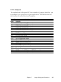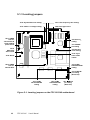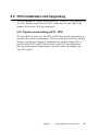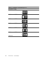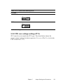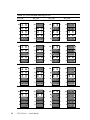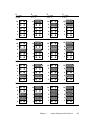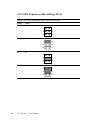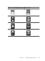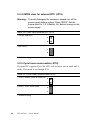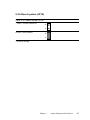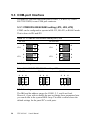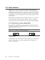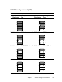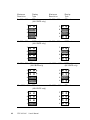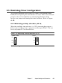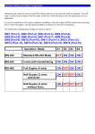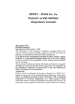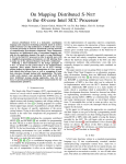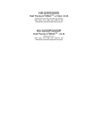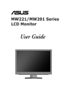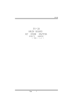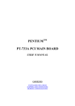
1
aces Chapter
This insert repl
CHAPTER
RT
E
S
N
I
5
R
E
T
P
A
NEW CH
d manual.
5 in the publishe
5
Jumper Settings and
Connectors
This chapter tells how to set up the panel
PC hardware, including instructions on
setting jumpers and connecting peripherals,
switches and indicators. Be sure to read
all the safety precautions before you
begin the installation procedures.
•
Jumpers and Connectors
•
CPU Installation and Upgrading
•
COM Port Interface
•
VGA Interface
•
Watchdog Timer Configuration
NSERT
I
5
R
E
T
P
A
H
C
NEW
l.
blished manua
pter 5 in the pu
aces Cha
This insert repl
5.1 Jumpers and Connectors
5.1.1 Setting jumpers
You can configure your panel PC to match the needs of your application
by setting jumpers. A jumper is the simplest kind of electrical switch. It
consists of two metal pins and a small metal clip (often protected by a
plastic cover) that slides over the pins to connect them. To “close” a
jumper, you connect the pins with the clip. To “open” a jumper you
remove the clip. Sometimes a jumper will have three pins, labeled 1, 2,
and 3. In this case, you would connect either pins 1 and 2 or pins 2 and 3.
1
Open
Closed
2
3
Closed 2 - 3
The jumper settings are schematically depicted in this manual as follows:
1
Open
Closed
Closed 2 - 3
A pair of needle-nose pliers may be helpful when working with jumpers.
If you have any doubts about the best hardware configuration for your
application, contact your local distributor or sales representative before
you make any changes.
44
PPC-120/140
User's Manual
5.1.2 Jumpers
The motherboard of the panel PC has a number of jumpers that allow you
to configure your system to suit your applications. The table below lists
the function of each of the board’s jumpers.
Table 5-1: Jumpers and their functions
Label
JP1
JP2
JP3
JP4
JP5
JP6
JP7
JP8
JP9
JP10
JP11
JP12
JP13
JP14
JP15
JP16
JP17
JP18
Function
COM3 RI pin setting (Reserved)
COM4 RI pin setting (Reserved)
COM2 RS-232/422/485 setting
COM2 RS-232/422/485 setting
COM2 RS-232/422/485 setting
Panel VCC setting
ENVEE pin setting
PCI bus clock setting
Panel type select
Cyrix linear mode enable
System/PCI clock setting
CMOS clear for external RTC
CPU VCORE voltage setting
CPU frequency ratio setting
Watchdog timer action
Reset
CMOS clear for 5582 internal RTC (Reserved)
AT/ATX power select (Reserved)
Chapter 5
Jumper Settings and Connectors
45
5.1.3 Locating jumpers
JP14: System/PCI clock setting
JP11: CPU frequency ratio setting
JP13: CPU VCORE voltage setting
JP9: Panel type select
JP17: CMOS
clear for
internal RTC &
JP18: AT/ATX
power select
Socket 7
JP6: Panel Vcc
setting
JP7: ENVEE
pin setting
JP8: PCI bus
clock setting
DIMM
JP15:
Watchdog
timer action
JP16: Reset
PCMCIA
JP10: Cyrix
linear mode
enable
JP5: COM2
RS-232/422/485
setting
JP12: CMOS
clear for
external RTC
JP2: COM4 RI
pin setting
(Reserved)
JP4: COM2
RS-232/422/485
setting
JP3: COM2
RS-232/422/485
setting
JP1: COM3 RI
pin setting
(Reserved)
Figure 5-1: Locating jumpers on the PPC-120/140 motherboard
46
PPC-120/140
User's Manual
5.1.4 Connectors
On-board connectors link the panel PC to external devices such as hard
disk drives or floppy drives. The table below lists the function of each of
the board’s connectors.
Table 5-2: Panel PC connectors
Label
J1
J2
J3
J4
J5
J6
J7
J8
J9
J10
J11
J12
J13
J14
J15
J16
Function
IR connector
Flat panel display connector
Flat panel display connector
Internal COM4 connector
Touchscreen power connector
Sandisk SSD connector
EIDE hard disk driver connector
Floppy drive connector
CD-ROM connector
CPU fan power connector
PCI/ISA bus expansion connector
Fan power connector
AT power connector
ATX power connector (Reserved)
Internal speaker connector
Inverter power connector
Chapter 5
Jumper Settings and Connectors
47
5.1.5 Locating connectors
J10: CPU fan power
connector
J7: EIDE hard disk
drive connector
J11: PCI/ISA
bus expansion
connector
J6: Sandisk SSD
connector
J5: Touchscreen
power connector
J12: Fan power
connector
J3: Flat panel
display connector
J14: ATX
power
connector
(Reserved)
J4: Internal COM4
connector
Socket 7
J13: AT power
connector
J2: Flat panel
display connector
DIMM
J16: Inverter
power
connector
PCMCIA
J9: CD-ROM
connector
J8: Floppy drive
connector
J15: Internal
speaker
connector
J1: IR connector
Figure 5-2: Locating connectors on the PPC-120/140 motherboard
48
PPC-120/140
User's Manual
5.2 CPU Installation and Upgrading
You can upgrade to a higher power Pentium®, AMD or Cyrix processor at
any time. Simply remove the old CPU, install the new one, and set the
jumpers for the new CPU type and speed.
5.2.1 System clock setting (JP11, JP8)
JP11 and JP8 are used to set the CPU and PCI bus speeds respectively, to
optimize the system's performance. The system chipset will sense the JP8
setting to get the bus frequency, then adjust its internal timing. JP11 is
used to set the CPU and PCI clock. Refer to the CPU speed reference
table for instructions on adjusting the internal clocks according to the
base CPU speed.
Chapter 5
Jumper Settings and Connectors
49
Table 5-3: System/PCI clock setting (JP11)
PCI clock CPU clock
25 MHz
50 MHz
1
30 MHz
60 MHz
1
33 MHz
66 MHz
1
28 MHz
55 MHz
1
38 MHz
75 MHz
1
42 MHz
83 MHz
1
(Reserved)
50
PPC-120/140
User's Manual
Table 5-4: PCI bus clock setting (JP8)
PCI clock
* CPUCLK/2
1
32MHz
1
* default setting
5.2.2 CPU core voltage setting (JP13)
JP13 must be set to match the CPU type. The chart below shows the
proper jumper settings for their respective Vcc (core). (The Vcc (I/O) for the
CPU is fixed at 3.3 V.)
Chapter 5
Jumper Settings and Connectors
51
Table 5-5: CPU voltage setting (JP13)
VCC (CORE)
1.30 V
VCC (CORE)
1.35 V
V CC (CORE)
1.45 V
10
9
10
9
10
9
10
9
8
7
8
7
8
7
8
7
6
5
6
5
6
5
6
5
4
3
4
3
4
3
4
3
2
1
2
1
2
1
2
1
1.50 V
1.55 V
1.60 V
1.65 V
10
9
10
9
10
9
10
9
8
7
8
7
8
7
8
7
6
5
6
5
6
5
6
5
4
3
4
3
4
3
4
3
2
1
2
1
2
1
2
1
1.70 V
1.75 V
1.80 V
1.85 V
10
9
10
9
10
9
10
9
8
7
8
7
8
7
8
7
6
5
6
5
6
5
6
5
4
3
4
3
4
3
4
3
2
1
2
1
2
1
2
1
1.90 V
52
VCC (CORE)
1.40 V
1.95 V
2.00 V
2.05 V
10
9
10
9
10
9
10
9
8
7
8
7
8
7
8
7
6
5
6
5
6
5
6
5
4
3
4
3
4
3
4
3
2
1
2
1
2
1
2
1
PPC-120/140
User's Manual
VCC (CORE)
NONE
V CC (CORE)
2.10 V
V CC (CORE)
2.20 V
VCC (CORE)
2.30 V
10
9
10
9
10
9
10
9
8
7
8
7
8
7
8
7
6
5
6
5
6
5
6
5
4
3
4
3
4
3
4
3
2
1
2
1
2
1
2
1
2.40 V
2.50 V
2.60 V
2.70 V
10
9
10
9
10
9
10
9
8
7
8
7
8
7
8
7
6
5
6
5
6
5
6
5
4
3
4
3
4
3
4
3
2
1
2
1
2
1
2
1
2.80 V
2.90 V
3.00 V
3.10 V
10
9
10
9
10
9
10
9
8
7
8
7
8
7
8
7
6
5
6
5
6
5
6
5
4
3
4
3
4
3
4
3
2
1
2
1
2
1
2
1
3.20 V
3.30 V
3.40 V
3.50 V
10
9
10
9
10
9
10
9
8
7
8
7
8
7
8
7
6
5
6
5
6
5
6
5
4
3
4
3
4
3
4
3
2
1
2
1
2
1
2
1
Chapter 5
Jumper Settings and Connectors
53
5.2.3 CPU frequency ratio setting (JP14)
Table 5-6: CPU frequency ratio (for Intel) (JP14)
P55C
3.5x
2x
3x
2.5x
54
P54C
1.5x
1
2
3
4
5
6
1
2
3
4
5
6
1
2
3
4
5
6
1
2
3
4
5
6
2x
3x
2.5x
PPC-120/140
User's Manual
Table 5-7: CPU frequency ratio (for AMD K6) (JP14)
2x
2.5x
1
2
1
2
3
4
3
4
5
6
5
6
1
2
1
2
3
4
3
4
5
6
5
6
3x
3.5x
4x
4.5x
1
2
1
2
3
4
3
4
5
6
5
6
1
2
1
2
3
4
3
4
5
6
5
6
5x
5.5x
Chapter 5
Jumper Settings and Connectors
55
5.2.4 CMOS clear for external RTC (JP12)
Warning: To avoid damaging the computer, always turn off the
power supply before setting “Clear CMOS”. Set the
jumper back to “3.0 V Battery On” before turning on the
power supply.
Table 5-8: Clear CMOS/External RTC (JP12)
* normal operation
1
2
Clear CMOS
1
2
* default setting
5.2.5 Cyrix linear mode enable (JP10)
The panel PC supports Cyrix M1 CPU with its linear access mode on L2
cache. This mode is set through JP10.
Table 5-9: Cyrix linear mode enable (JP10)
* open = disable (normal operation)
2
1
closed = Cyrix linear mode
2
1
* default setting
56
PPC-120/140
User's Manual
5.2.6 Reset system (JP16)
Table 5-10: Reset system (JP16)
* open = normal operation
2
1
closed = reset system
2
1
* default setting
Chapter 5
Jumper Settings and Connectors
57
5.3 COM-port Interface
The panel PC provides four serial ports (COM1, 3, 4: RS-232; COM2:
RS-232/422/485) in one COM port connector.
5.3.1 COM2 RS-232/422/485 setting (JP3, JP4, JP5)
COM2 can be configured to operate in RS-232, RS-422, or RS-485 mode.
This is done via JP6 and JP5.
Table 5-11: COM2 RS-232/422/485 setting (JP3, JP4)
* RS-232
RS-422/485
2
6
JP4
2
6
1
5
2
6
1
5
JP4
1
5
2
6
JP3
JP3
1
5
* default setting
Table 5-12: COM2 RS-232/422/485 setting (JP5)
* RS-232
RS-422
RS-485
2
4
6
2
4
6
2
4
6
1
3
5
1
3
5
1
3
5
* default setting
The IRQ and the address ranges for COM1, 2, 3, and 4 are fixed.
However, if you wish to disable the port or change these parameters later
you can do this in the system BIOS setup. The table overleaf shows the
default settings for the panel PC’s serial ports.
58
PPC-120/140
User's Manual
COM1 and COM2 are one set. You can exchange the address range and
interrupt IRQ of COM1 for the address range and interrupt IRQ of
COM2. After exchanging, COM1's address range is 2F8 ~ 2FF and its
request IRQ is IRQ3: and COM2's address range is 3F8 ~ 3FF and its
interrupt IRQ is IRQ4.
COM3 and COM4 are another set. Their selectable function is the same
as the COM1/COM2 set.
Table 5-13: PPC-120/140 serial port default settings
Port
COM1
COM2
COM3
COM4
Address Range
3F8 ~ 3FF
2F8 ~ 2FF
3E8 ~ 3EF
2E8 ~ 2EF
Interrupt
IRQ4
IRQ3
IRQ10
IRQ5
5.3.2 COM3/COM4/RI pin setting (JP2, JP1) (Reserved)
Table 5-14: COM4/RI pin setting (JP2)
+5 V output
+12 V output
* RI output
6
5
6
5
6
5
4
3
4
3
4
3
2
1
2
1
2
1
* default setting
Table 5-15: COM3/RI pin setting (JP1)
+5 V output
+12 V output
* RI output
6
5
6
5
6
5
4
3
4
3
4
3
2
1
2
1
2
1
* default setting
Chapter 5
Jumper Settings and Connectors
59
5.4 VGA Interface
The panel PC's’s PCI SVGA interface can drive conventional CRT
displays and is capable of driving a wide range of flat panel displays,
including electroluminescent (EL), gas plasma, passive LCD and active
LCD displays. The board has two connectors to support these displays
simultaneously; one for standard CRT VGA monitors and one for flat
panel displays.
CRT display port information can be found in Section 3.9 - VGA Port.
The pin assignments for the flat panel display connector, backlight
connector and other related connectors are described in the appendices.
5.4.1 LCD panel VCC power setting (JP6)
The panel PC's’s PCI SVGA interface supports 5 V and 3.3 V LCD
displays. By changing the setting of JP6, you can select the panel video
signal level to be 5 V or 3.3 V.
Table 5-16: LCD panel VCC power setting (JP6)
3.3 V
1
2
3
1
1
*5V
2
3
* default setting
Configuration of the VGA interface is done exclusively via the software
utility. You do not have to set any jumpers. Refer to Chapter 8 for
software setup details.
60
PPC-120/140
User's Manual
5.4.2 Panel type select (JP9)
Table 5-17: Panel type select (JP9)
Maximum
Resolution
1. 1024 x 768
Display
Type
DSTN color
Maximum
Resolution
2. 1280 x 1024
Display
Type
TFT color
7
8
7
8
5
6
5
6
3
4
3
4
1
2
1
2
3. 640 x 480
DSTN color
4. 800 x 600
DSTN color
7
8
7
8
5
6
5
6
3
4
3
4
1
2
1
2
5. 640 x 480
SHARP TFT color
6. 640 x 480
18-bit TFT color
7
8
7
8
5
6
5
6
3
4
3
4
1
2
1
2
7. 1024 x 768
TFT color
8. 800 x 600
TFT color
7
8
7
8
5
6
5
6
3
4
3
4
1
2
1
2
Chapter 5
Jumper Settings and Connectors
61
Maximum
Resolution
9. 800 x 600
Display
Type
TFT color
(44 K BIOS only)
8
7
8
5
6
5
6
3
4
3
4
1
2
1
2
DSTN color
(44 K BIOS only)
12. 800 x 600
DSTN color
7
8
7
8
5
6
5
6
3
4
3
4
1
2
1
2
13.1024 x 768 TFT color
(44 K BIOS only)
14. 1280 x 1024
DSTN color
(44 K BIOS only)
7
8
7
8
5
6
5
6
3
4
3
4
1
2
1
2
15. 1024 x 600
PPC-120/140
Display
Type
TFT color
7
11. 800 x 600
62
Maximum
Resolution
10. 800 x 600
TFT color
(48•K BIOS only)
16. 1024 x 600
TFT color
7
8
7
8
5
6
5
6
3
4
3
4
1
2
1
2
User's Manual
5.5 Watchdog Timer Configuration
An on-board watchdog timer reduces the chance of disruptions which
EMP (electromagnetic pulse) interference can cause. This is an invaluable
protective device for standalone or unmanned applications. Setup
involves one jumper and running the control software. (Refer to Appendix B.)
5.5.1 Watchdog activity selection (JP15)
When the watchdog timer activates (i.e. CPU processing has come to a
halt), it can reset the system or generate an interrupt on IRQ11. This can
be set via jumper JP15 as shown below:
Table 5-18: Watchdog activity selection (JP15)
* System reset
3
IRQ11
3
1
2
2
1
1
* default setting
Chapter 5
Jumper Settings and Connectors
63
64
PPC-120/140
User's Manual