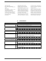
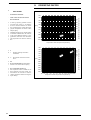
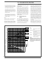
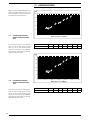
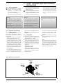
1
English
WSH
R134a
TECHNICAL MANUAL - INSTALLATION - MAINTENANCE
Water to water chiller, with screw compressors
❄
166 kW÷ 672 kW
IWSHPY. 0809. 4471121_00
❊ 183 kW ÷ 784 kW
Dear Customer,
Thank you for choosing an AERMEC product. It is the result of long experience and design-specific research.The article
has been made of materials of the highest quality and incorporates cutting edge technology.
In addition, all our products bear the EC mark indicating that they meet the requirements of the European Machine
Directive regarding safety. The standard of quality is permanently being monitored and AERMEC products are
therefore a synonym of Safety, Quality and Reliability.
The data might undergo modifications considered necessary for the improvement of the product at any time, without
the obligation for any notice thereof.
Thank you again.
AERMEC S.p.A
2
Summary
13.3.
13.4.
13.5.
13.6.
13.7.
Compressor fuses note ..................................................................... 18
Double high pressure switch ........................................................... 18
High pressure transducer................................................................ 18
Low pressure transducer ................................................................. 18
Refrigerator circuit safety valves .................................................. 18
Product identification ......................................................................5
14.
14.1.
Dimensions .......................................................................................19
Dimensional tables............................................................................... 19
4.
4.1.
4.2.
4.3.
Unit description .................................................................................6
Versions available ....................................................................................6
Available versions ....................................................................................6
Configurator...............................................................................................6
15.
15.1.
Weights and centre of mass .....................................................20
Percentage distribution of weights on supports .................... 21
5.
5.1.
5.2.
5.3.
5.4.
5.5.
Description of components ...........................................................7
Refrigerating circuit ...............................................................................8
Frame ...........................................................................................................8
Safety and control components ........................................................8
Electrical components ...........................................................................8
Electronic regulation ..............................................................................8
16.
16.1.
Handling .............................................................................................22
Instructions for lifting .........................................................................22
17.
17.1.
17.2.
17.3.
Safety warnings and regulations of installation ...............23
Safety warnings .....................................................................................23
Selection of the installation location.............................................23
Positioning ...............................................................................................23
6.
Accessories .........................................................................................9
7.
Technical data ..................................................................................10
18.
18.1.
18.2.
Hydraulic circuit .............................................................................24
WSH Internal hydraulic circuit........................................................24
WSH external hydraulic circuit (not supplied) .........................24
8.
8.1.
Operational limits ........................................................................... 11
Design date dir 97/23/ce...............................................................11
9.
9.1.
9.2.
9.3.
9.4.
Corrective factor ...........................................................................12
Cooling capacity and input power .................................................. 12
Heating capacity and input power ................................................. 13
For ∆t different from the rated value.......................................... 13
Fouling factors ....................................................................................... 13
19.
19.1.
19.2.
19.3.
19.4.
Position of hydraulic connections ............................................25
Standard version (°) ............................................................................25
Quiet operation version (L) ...............................................................25
Desuperheater version (D)...............................................................26
Low noise with desuperheater version (DL) .............................26
20.
20.1.
Electrical connections .................................................................. 27
Electrical data ........................................................................................ 27
10.
10.1.
Ethylene glycol solution................................................................14
How to read glycol curves ................................................................ 14
11.
11.1.
11.2.
Pressure drop ................................................................................16
Evaporator pressure drops in cooling operation ................... 16
Condenser pressure drops in cooling operation .................... 16
21.
21.1.
21.2.
21.3.
Putting into service .......................................................................28
Preparation for commissioning .....................................................28
Commissioning ......................................................................................28
System discharge ...............................................................................29
12.
12.1.
12.2.
Sound data ........................................................................................ 17
Sound power............................................................................................17
Sound pressure......................................................................................17
22.
22.1.
22.2.
Maintenance ....................................................................................29
Maintenance warnings .....................................................................29
Extraordinary maintenance .............................................................29
23.
23.1.
Disposal..............................................................................................30
Disconnecting the unit....................................................................... 30
13.
13.1.
13.2.
Control and safety parameters setting ...............................18
Compressor magnetothermal switch 400v ............................ 18
Compressor thermal cut-out ......................................................... 18
24.
24.1.
Improper uses .................................................................................30
Important safety information ......................................................... 30
1.
1.1.
1.2.
Warnings on the documentation ................................................5
Intended use ..............................................................................................5
Conservation of the documents ........................................................5
2.
Essential safety rules ......................................................................5
3.
To install the unit, please observe the safety warnings included in these instructions
Danger: moving parts
Danger: cut off power supply
Danger: high temperature
General danger
Danger: power supply
i
Useful information and warnings
3
AERMEC S.P.A.
I-37040 Bevilacqua (VR) Italy – Via Roma, 44
Tel. (+39) 0442 633111
Fax 0442 93730 – (+39) 0442 93566
www.aermec.com - [email protected]
WSH
SERIAL NUMBER
DECLARATION OF CONFORMITY
We, the undersigned, declare on our own exclusive responsibility that the object in
question, so defined:
NAME
WSH
TYPE
CHILLER, HEAT PUMP WATER TO WATER
Model
To which this declaration refers, complies with the following standardised regulations:
CEI EN 60335-2-40
Safety regulation regarding electric heat pumps, air conditioners and dehumidifiers
CEI EN 61000-6-1
CEI EN 61000-6-3
Electromagnetic immunity and emission in residential environment
CEI EN 61000-6-2
CEI EN 61000-6-4
Electromagnetic immunity and emission in industrial environment
EN378
Refrigerating system and heat pumps - Safety and environmental requirements
UNI EN 12735
Round weldless copper pipes for air conditioning and cooling
UNI EN 14276
Pressure equipment for refrigerating systems and heat pumps
Thus meeting the essential requisites of the following directives:
- LV Directive: 2006/95/EC
- Electromagnetic Compatibility Directive 2004/108/EC
- Machine Directive 98/37/EC
- PED Directive relating to pressure equipment 97/23/EC
In compliance with Directive 97/23/EC, the product meets the Full quality assurance procedure (module H) with certificate no.
06/270-QT3664 Rev.3 issued by the notified body no. 1131 CEC via Pisacane 46 Legnano (MI) - Italy
Bevilacqua
14/12/2007
Marketing Director
Signature
4
1.
1.1.
WARNINGS ON THE DOCUMENTATION
INTENDED USE
WSH AERMEC chillers have been built
according to the technical standards and
the recognised safety regulations. These
units have been designed and manufactured for cooling and must be used accordingly, and taking into account their
performance characteristics. There may
still arise risks for the safety of the user
or third parties, or even damage to the
units and other objects, in case of improper use.
Any use not specifically indicated in this
manual is forbidden. Therefore, AERMEC
shall not be held responsible for any
damage whatsoever resulting from the
non-compliance with these instructions
1.2.
CONSERVATION OF THE
DOCUMENTS
Deliver the following installation instructions with all the complementary documentation to the user of the unit, who
shall be responsible for keeping the instructions so that they are always available when needed.
READ CAREFULLY THIS CHAPTER, the
unit must be installed by qualified skilled
2.
Remember that the use of products that
use electric power and water carries the
compliance with some essential safety
rules such as:
The use of this unit is not intended for
people (including children) with any
physical or mental disability or any
sensory impairment nor for people
lacking experience and knowledge,
unless they are supervised or instructed on the use of the unit by a person
responsible for their safety. Children
should be supervised in order to
make sure that they do not play with
the unit.
personnel, in compliance with the national
legislation in force in the country of destination. The unit must be installed in such
a way as to make all maintenance and/or
repair operations possible. The warranty
of the device does not in any case cover
costs incurred as a result of motorised
ladders, scaffolding or any other lifting systems made necessary to carry out the
operations under warranty.
The warranty shall not be valid if the indications mentioned above are not observed.
ESSENTIAL SAFETY RULES
It is forbidden to carry out any technical or maintenance operation before disconnecting the unit from the
mains by positioning the system and
control panel main switches on “off”.
It is forbidden to modify safety or regulation devices without the manufacturer's authorisation and indications
It is forbidden to pull, disconnect or
twist the outcropping electrical cables of the unit even if it has been disconnected from the mains
It is forbidden to leave containers
and flammable substances near the
chiller.
3.
It is forbidden to touch the unit with
wet parts of the body and bare feet.
It is forbidden to open the access doors to the unit internal parts, without
having first turned off the system
main switch.
It is forbidden to spread, leave or
keep the packaging material within
the reach of children as it may be a
possible source of danger.
PRODUCT IDENTIFICATION
WSH can be identified by:
- Packaging label
that includes the product identification data
- Technical card
Placed on the electronic box side sill.
NOTE
If the identification plate, or any other
means to identify the product, is tampered with, removed or missing, installation and maintenance operations are
hampered
PACKAGING
LABEL
TECHNICAL
CARD
5
4.
UNIT DESCRIPTION
The units from the WSH series are
water chillers water condensed for residential and industrial use. The machine is designed for the management of
both hydraulic circuits: (evaporator and
condenser); therefore, it can be used
not only as a water chiller but also to
produce hot water.
The commutation between "COOL HEAT" is obtained by managing the
cooling circuit.
The whole series includes models with
one or two twin-screw compressors
and are fitted with star - delta start to
reduce the starting current.
All the units are tested and delivered
complete with refrigerant load and
oil, (it will be necessary only to make
hydraulic and electrical connections on
site).
All units have a protection class of IP20
.
The new WSH series is characterised
by the use of refrigerant R134a, which
allows reaching performances significantly superior to equivalent products
that operate with R407C.
This is also the result of a thorough study and dimensioning of all the internal
components in order to make the most
of the refrigerant gas characteristics.
4.1.
4.3.
9
10
11
12
13
WSH
2502
X
°
D
°
°
°
(1)
Code
WSH
4, 5, 6, 7 Size
6
With the aid of the configurator, it is
possible to set up and then order the
chiller that best suits the needs of
users or whoever stands in for them.
CONFIGURATOR
8
9
AVAILABLE VERSIONS
CAUTION
Before each start-up operation of the
unit (or at the end of each extended
pause period) it is extremely important
to preheat the oil in the compressor casing, by means of the suitable electric
4,5,6,7
8
4.2.
VERSIONS AVAILABLE
- “HEAT PUMP (H)”
1,2,3
Field
1, 2 ,3
heaters, during at least 8 hours. The
casing heating element is automatically
powered when the unit pauses so that
the unit is kept powered up.
0701 - 0801 - 0901 - 1101 - 1402 - 1602 1802 - 2002 - 2202 - 2502
Field of use
°
Standard with processed water above +4"C
X
With electronic thermostatic valve that permits:
- Chiller water up to - 6°C
- Control of the cooling capacity with continual
modulation (25 - 100%)
Model
°
Standard
10
Heat recovery units
°
Without recovery units
D
Desuperheater
11
Version
°
L
Standard
Quiet operation
12
Heat exchangers
°
Standard according to PED
14
Power supply
°
3~ 400V - 50 Hz with fuses
2
3~ 230V - 50 Hz with fuses
4
3~ 230V - 50 Hz with thermomagnetic switches
5
3~ 500V - 50 Hz with fuses
8
3~ 400V - 50 Hz with thermomagnetic switches
9
3~ 500V - 50 Hz with thermomagnetic switches
ELECTRONIC VALVE
"ELECTRONIC EXPANSION VALVES" are characterised
by a high regulation capacity that allows compressors
to always work in the best possible operating conditions (compatible with the outdoor ambient conditions).
In winter it is therefore possible to work with very low
condensation pressure, improving the efficiency of compressors and reducing power consumption.
With the electronic valve in our chillers, temperature
adjustment is more efficient, as it is possible to obtain
lower working temperatures making the best use of
the evaporator surface. Besides, the system does not
require future settings or adjustments, since the electronic valve operates continuously its control function
according to the parameters obtained from the transducers, keeping optimum overheating values. Apart from
better pressure conditions, there are better temperature conditions for the compressors, keeping discharge
temperatures lower than the ones obtained when using
the standard thermostatic valve. This results in a longer
service life for the compressor and a reduction in the
number of failures.
To summarise, the advantages of using the electronic
valve are:
- Energy saving in the system consumption levels
- Better working conditions for compressors (lower
pressure and lower discharge temperature), which results in less failures and a reduction in the maintenance
costs.
- Continuity of performance throughout time
- Less deterioration of the compressor mechanical parts
and of the lubricating oil
- Repeatability of the adjustment and energy consumption results throughout time.
All this in acknowledgement of AERMEC commitment to
and respect for the problems related to energy saving
and conscious and socially responsible use of the available
resources.
DESCRIPTION OF COMPONENTS
14
5.
11
8
7
6
5
4
3
12
2
13
1
Example WSH 1802 °
KEY
1
2
3
4
5
9
10
6
7
8
9
10
11
12
13
14
Compressors
Liquid indicator
Filter drier
Economiser
Thermostatic valve
economiser
Solenoid valve
economiser side
Filler valve
One directional valve
Evaporator
Condenser
Cycle inversion valve
Safety valve (low pressure side)
Safety valve (high pressure side)
Electronic box
7
5.1.
REFRIGERATING CIRCUIT
Compressors
Semi hermetic high-efficiency bi-screw
compressors, with a cooling capacity
regulation by means of continuous
modulation from 40 to 100% (from
25 to 100% with electronic valve) and
fitted with:
- Thermal motor protection
- Oil discharge temperature check
- Electric heater for the heating of the
oil casing with the compressor at a
standstill
- Reset button.
Exchanger (condenser)
Of the plate type (AISI 316), it is insulated externally with closed cell material
to reduce thermal dispersions.
Exchanger (evaporator)
Of the plate type (AISI 316), it is insulated externally with closed cell material
to reduce thermal dispersions.
Economiser
Plate type (AISI 316). This allows the
additional cooling of the refrigerant
exiting the condenser and at the same
time creates a vapour to be injected
in an intermediate point of the condensing process; reducing both the
delivery temperature as well as the
electrical absorption.
Filter drier
Of the mechanical type made of ceramics and hygroscopic material able to
trap impurities and any traces of humidity in the cooling circuit.
Liquid indicator
For checking that the refrigerant gas
load and any humidity in the cooling circuit.
Thermostatic valve
The mechanical type valve with outside
equaliser on the evaporator outlet modulates the gas flow to the evaporator
dependent on the thermal load in such
a way as to ensure the proper intake
gas degree of overheating.
Thermostatic valve (economiser)
The mechanical type valve with outside
equaliser on the economiser outlet, on
the inlet of the compressor to improve
performance.
Solenoid valve
The valve closes when the compressor
8
turns off, preventing the flow of refrigerant gas towards the evaporator.
in the case of abnormal operating pressures.
One way valve
This allows the refrigerant to flow in
just one direction.
5.4.
Mechanical filter
Positioned in the liquid injection line to
the compressor, it retains the impurities that may be present in the refrigerant circuit.
5.2.
FRAME
Load-bearing structure
Made of hot galvanised steel sheet of
adequate thickness, it is painted with
polyester powders able to resist the
atmospheric agents over time. Colour
RAL 9002.
Acoustic protection cover
(silenced versions)
IT is made of hot galvanised steel sheet of adequate thickness, with internal
acoustic insulation, and externally painted with polyester powders able to resist the atmospheric agents over time.
Colour RAL 9002.
5.3.
SAFETY AND CONTROL COMPONENTS
High pressure switch
(manual + automatic)
Factory-calibrated, it is placed on the
high pressure side of the cooling circuit, it shuts down compressor operation
in the case of abnormal operating pressure.
Low pressure transducer
It makes it possible to show the value of
the compressor's intake pressure (one
per circuit) on the microprocessor card
display. Placed on the low pressure
side of the cooling circuit, it shuts down
compressor operation in the case of
abnormal operating pressure.
High pressure transducer
It makes it possible to show the value
of the compressor's delivery pressure
(one per circuit) on the microprocessor
card display. Placed on the high pressure side of the cooling circuit, it shuts
down compressor operation in the case
of abnormal operating pressure.
Cooling circuit safety valves (HP - LP)
Calibrated to 22 bar HP and 16.5 LP,
they cut in relieving the overpressure
ELECTRICAL COMPONENTS
Electrical panel
Contains the power section and the
management of the controls and
safety devices. This conforms with
standard CEI 60204-1, and electromagnetic compatibility directives EMC
89/336/CEE and 92/31/CEE.
CPCE valve
Hot gas injection device up stream of
the evaporator, fitted on the partial or
total heat recovery versions.
NOTE
Furthermore, all the cables are wired
for immediate recognition of all the
electrical components.
Door lock knife switch
THE electrical panel can only be accessed by cutting off power using the opening lever on the panel itself. This lever
can be locked in place using one or
more padlocks, during maintenance
in order to prevent the machine being
powered up accidentally.
Control keypad
Provides full control functions. For a
detailed description of the keypad refer
to the user manual.
- secondary thermomagnetic switch protection
5.5.
ELECTRONIC REGULATION
Electronic regulation on the "WSH" chillers consists of control cards (pCO2) for
each compressor connected to each
other in a network and a control panel
with display. In the case of models with
more compressors, the card that controls compressor 1 is the "MASTER"
card, while the others are "SLAVE". On
each card, the transducers, loads and
alarms corresponding to the compressor that commands are connected,
while the general machine ones are
connected only on the "MASTER card.
Microprocessor
- Remot e on/of f wit h ext ernal
contact without power
- Multilingual menu
- Phase sequence control
- Independent control of individual
compressors
- Ammeter transformer
- Cumulative failure block signalling
- Alarm log function
- Daily/weekly programming
- Inlet/outlet water temperature
display
- Alarm display
- Full proportional regulation of the
output water temperature
- Programmable timer function
- Function with double setting point
connected to an external contact
- Interfaceability with the Modbus
protocol (accessory)
- Pump control
-
Compressor rotation control
Analogue input from 4 to 20 mA
Outside air temperature sensor
“Always Working” function. In the
case of critical conditions (e.g. an
ambient temperature that is too
high) the machine does not stop but
is able to regulate itself and provide
the maximum power that can be
generated in those conditions.
- Self adapting operating differential
“Switching Histeresys” to ensure
the correct compressor functioning
6.
ACCESSORIES
0701
0801
0901
1101
1402
1602
1802
2002
2202
2502
Through this accessory it is possible to connect the unit with BMS supervision systems with
electrical standard RS 485 and MODBUS type protocol.
•
•
•
•
•
•
•
•
•
•
AER485P2
AVX
Sprung vibration damping supports.
°
D
PRV
665
665
665
665
665
665
666
666
662
662
662
662
662
662
663
663
664
664
664
664
This allows the refrigerator command operations to be given from a distance.
•
•
•
•
•
•
•
•
•
•
The ROMEO device makes it possible to remotely control the chiller from an ordinary cell
phone with WAP browser, it also makes it possible to send alarm and pre-alarm SMS to up
to three GSM cell phones even if they are not fitted with the WAP browser. The set includes
the AER485. The accessory AER485P2 must be added to this kit.
•
•
•
•
•
•
•
•
•
•
ROMEO
RIF
(on the 400V - 3 - 50 HZ VERSIONS ONLY)
at all times even in plants with a
low water content or insufficient
flow rates. This system reduces the
compressor wear
- The PDC “Pull Down Control”
system to prevent the activation of
the power steps when the water
temperature is approaching the
set point quickly. It optimises the
operation of the machine both when
running normally or when there are
load variations, thereby assuring top
machine efficiency in all situations
(1)
Parallel connection with the motor makes the reduction of input current possible.
161
161
201
241 161 x 2 161 x 2 201 x 2 201 + 241 241 x 2 301 x 2
MULTICHILLER
Control system to command, turn on and off the individual chillers in a system in which several
units are installed in parallel. It is possible to select it among different command logics: sequential, homogenous, combined. The accessory is delivered in IP65 box.
•
•
•
•
•
•
•
•
•
•
AKW: ACOUSTIC KIT
This accessory allows additional reduction of the noise by means of:
- Hood of the machine optimised by high density lead free materials which allow further
reduction of vibrations.
L
L
L
L
L
L
L
L
L
L
(1) Accessory that can only be installed in the factory
9
7.
TECHNICAL DATA
WSH
COOLING ONLY
Cooling capacity:
Total input power
Evaporator water flow rate
Evaporator pressure drop
Condenser water flow rate
Condenser pressure drop
kW
kW
l/h
kPa
l/h
kPa
HEATING
Heating capacity
Total input power
Condenser water flow rate
Condenser pressure drop
Evaporator water flow rate
Evaporator pressure drop
kW
kW
l/h
kPa
l/h
kPa
ENERGY INDICES
EER
EEC
COP
EEC
W/W
ELECTRICAL DATA
Power supply
Total input power
Maximum current
Peak current
V
A
A
cool
hot
FLA
LRA
A
A
0701
166
36
28550
23
34740
30
0801
196
41
33710
24
40760
31
0901
217
47
37320
22
45410
30
1101
270
57
46440
27
56240
36
1402
360
76
61920
43
74990
57
1602
428
88
73620
47
88750
62
1802
466
99
80150
48
97180
65
183
44
31480
24
23910
15
210
50
36120
23
27520
15
237
300
420
57
72
98
40760 51600 72240
23
29
57
30960 39220 55380
14
18
27
490
116
84280
62
64330
29
540
620
700
784
125
144
162
176
92880 106640 120400 134850
63
72
79
90
71380 81870 92540 104580
29
32
36
40
4,61
C
4,16
B
4,78
B
4,20
B
4,62
C
4,16
B
4,74
B
4,17
B
65
81
124
163
73
91
144
192
80,6
101
162
229
twinscrew
1
1/1
twinscrew
1
1/1
twinscrew
1
1/1
4,74
B
4,29
B
2002
2202
526
594
109
120
90470 102170
59
65
109220 122810
79
88
2502
672
138
115580
74
139320
101
4,86
B
4,22
B
4,71
B
4,32
B
4,83
B
4,31
B
4,95
B
4,32
B
4,87
B
4,45
A
100
130,5
182
300
400V-3-50Hz
135
146,5
178,5
210
248
288
287
336
162
221
324
391
187,5
256,5
344
462
210
291
364
482
242
320
430
575
twinscrew
1
1/1
twinscrew
2
2/2
twinscrew
2
2/2
twinscrew
1+1
2/2
twinscrew
2
2/2
twinscrew
2
2/2
Compressors
Type
Number
Number per circuit
n°
n°/n°
twinscrew
2
2/2
CAPACITY CONTROL
Capacity control
VT
VT
°
x
EVAPORATOR
Type
Number
Hydraulic connections
CONDENSER
Type
Number
Hydraulic connections
SOUND DATA
Sound power
Sound pressure
DIMENSIONS - outdoor installation
(°)
Height
L
Height
Width
Length
(°)
Weight
Weight
L
%
%
1
V/3"
1
V/3"
1
V/3"
1
V/3"
Plates
1
1
V/3"
V/3"
1
V/3"
1
V/3"
1
V/3"
1
V/3"
n°
1
V/3"
1
V/3"
1
V/3"
1
V/3"
Plates
1
1
V/3"
V/3"
1
V/3"
1
V/3"
1
V/3"
1
V/3"
dB(A)
86.0
54.0
86.0
54.0
86.0
54.0
92.0
60.0
89.0
57.0
89.0
57.0
89.0
57.0
93.0
61.0
95.0
63.0
95.0
63.0
2050
2120
809
2960
1391
1622
2050
2120
809
2960
1443
1674
2050
2120
809
2960
1506
1737
2050
2120
809
3360
1946
2206
2050
2120
1249
3060
2276
2542
2050
2120
1249
3060
2350
2616
2050
2120
1249
3060
2423
2689
2050
2120
1249
3460
2872
3168
2050
2120
1249
3460
3309
3605
2050
2120
1249
3460
3407
3703
n°
Type/ø
dB(A)
mm
mm
mm
mm
kg
kg
DATA STATED ACCORDING TO EN14511:2004
Automatic
- Processed water temperature
7 °C
- Condenser inlet water temperature 30 °C
- ∆t
5k
10
40-100 40-100 40-100 40-100 20-100 20-100 20-100 20-100 20-100 20-100
25-100 25-100 25-100 25-100 12.5-100 12.5-100 12.5-100 12.5-100 12.5-100 12.5-100
Heating
- Processed water temperature
45 °C
- Evaporator inlet water temperature 10 °C
- ∆t
5k
- Sound pressure measured 10 m. away in the
open, with direction factor Q=2 according to
ISO 3744
- Sound power The Aermec sound power value
is determined on the basis of measurements
taken in accordance with the ISO 9614-2
standard, in compliance with what is required
by the EUROVENT Certification
8.
OPERATIONAL LIMITS
Condenser outlet water temperature °C
Field of use ( ° )
55
50
45
40
35
30
25
-6
-4
-2
0
2
4
6
8
10 12 14 16
Field of use ( X )
Evaporator outlet water temperature °C
KEY
Glycol operation
Standard operation
8.1.
DESIGN DATE
DIR 97/23/CE
HIGH PRESSURE
SIDE
LOW PRESSURE
SIDE
Maximum pressure allowable
bar
22
16.5
Maximum setting allowable
°C
120
55
Minimum temperature allowable
°C
-10
-10
11
9.
COOLING CAPACITY AND
INPUT POWER
- “STANDARD VERSIONS”
1.70
- “HEAT PUMP IN COOLING OPERATION VERSIONS”
1.60
1.50
55°C
The cooling capacity yielded and the
input electrical power in conditions
other than rated conditions are obtained by multiplying the rated values (Pf,
Pa) by the respective correction coefficients (Cft, Cpa).
The following diagrams are used to obtain
the correction coefficients to be used for
the units, in the different versions, in cooling operation; next each curve the external air temperature to which it refers is
shown.
1.40
50°C
(Ca) 1.30
45°C
40°C
1.20
35°C
1.10
30°C
1.00
0.90
25°C
0.80
0.70
Condenser outlet water temperature °C
9.1.
CORRECTIVE FACTOR
-6 -5 -4 -3 -2 -1 0 1 2 3 4 5 6 7 8 9 10 11 1213 14 15 16
Evaporator water temperature (∆t=5°C)
KEY:
Cf =
Ca =
Cooling capacity correction
coefficient
Input power correction coefficient
NOTE:
FOR THE X VERSIONS with temperatures below 4 °C contact the company
FOR ∆T DIFFERENT FROM 5°C
to the evaporator refer to Tab.9.3.1 for
cooling capacity and input power correction factors. To account for exchanger soiling, apply the relative fouling factors (tav. 9.4.1)
12
1.40
1.30
1.20
1.10
1.00
(Cf) 0.90
0.80
°C
30
°C
25
C
35°
C
°
0
4
C
45°
C
50°
C
°
55
0.70
0.60
0.50
0.40
0.30
-6 -5 -4 -3 -2 -1 0 1 2 3 4 5 6 7 8 9 10 11 1213 14 15 16
Evaporator water temperature °C (∆t=5°C)
Condenser outlet water temperature °C
1.50
9.2.
HEATING CAPACITY AND
INPUT POWER
1.50
1.40
The yields are intended as net of the
defrosting cycles.
1.30
55°C
1.20
50°C
45°C
(Ca) 1.10
40°C
35°C
1.00
090
30°C
0.80
25°C
0.70
0.60
-6 -5 -4 -3 -2 -1 0 1 2 3 4 5 6 7 8 9 10 11 1213 14 15 16
Evaporator water temperature (∆t=5°C)
1.50
1.40
°
30
°C
35 C
°
4 0 °C
405°C
5 °C
55
C
1.30
KEY:
Ct =
Ca =
Heating capacity correction
coefficient
Input power correction coefficient
1.20
°C
25
(Ct) 1.10
1.00
0.90
0.80
0.70
0.60
9.3.
FOR ∆T DIFFERENT FROM
THE RATED VALUE
For ∆t different from 5°C to the evaporator refer to Tab.9.3.1 for cooling
capacity and input power correction
factors. To account for exchanger soiling, apply the relative fouling factors
(tab. 9.4.1)
Condenser outlet water temperature °C
The heating capacity yielded and the
input electrical power in conditions
other than rated conditions are obtained by multiplying the rated values (Pf,
Pa) by the respective correction coefficients (Cft, Cpa).
The following diagram makes it possible to obtain the corrective coefficients; corresponding to each curve,
the temperature of the hot processed
water referred to is reported, assuming a difference in water temperature between the input and output of the
condenser equal to 5°C.
Condenser outlet water temperature °C
- “HEAT PUMP VERSIONS”
-6 -5 -4 -3 -2 -1 0 1 2 3 4 5 6 7 8 9 10 11 1213 14 15 16
Evaporator water temperature (∆t=5°C)
9.3.1 Correction factors for ∆t different from the Chiller Rated value
Cooling capacity correction factors
Input power correction factors
3
0.99
0.99
5
1
1
8
1.02
1.01
10
1.03
1.02
[K*m2]/[W]
0.00005
1
1
0.0001
0.98
0.98
0.0002
0.94
0.95
9.4.1 Fouling factors
9.4.
FOULING FACTORS
The performances supplied by the
table refer to the conditions of clean
pipes with fouling factor = 1. For values
different from the fouling factor, multiply the values in the performance table
by the coefficients reported.
Cooling capacity correction factors
Input power correction factors
13
10. ETHYLENE GLYCOL SOLUTION
- The cooling capacity and input power
correction factors take into account
the presence of glycol and the different evaporation temperature.
- The pressure drop correction factor already takes into account the
different flow rate deriving from the
application of the water flow rate
correction factor.
- The water flow rate correction factor is calculated in such a way as to
keep the same ∆t that there would
be without glycol.
NOTE
To make it easier to read the graph, an
example is given on the next page.
By using the diagram below it possible
to establish the percentage of glycol
necessary; this percentage can be cal-
culated taking into account one of the
following factors:
On the basis of the fluid considered
(water or air), it will be necessary to
enter the graph from the right or left
side, from the intersection of the outside air temperature or processed
water temperature straight lines and
the relative curves, a point is obtained
through which the vertical line that will
identify both the percentage of glycol
and the relative corrective coefficients
will have to pass.
10.1.
HOW TO READ GLYCOL
CURVES
The curves shown in the figure sum
up a considerable quantity of data, all
of which is represented by a specific
curve. To be able to use these curves
in the proper way, it is necessary to
make some initial considerations:
FcGDpF (a)
2.20
2.10
2.00
FcGDpF (b)
FcGDpF (c)
1.90
1.80
1.70
FcGDpF (d)
1.60
FcGDpF (e)
1.50
1.40
1.30
1.20
FcGQ (PdC)
1.10
FcGPf (PdC)
098
0.97
FcGPa
0.96
0.95
0.94
5
5
0
-5
0
-6
-10
-15
-20
-25
-30
-35
-40
0
14
5
10
15
20
25
30
35
40
45
50
55
Temperature
Temperatura
processed
water°C
°C
acqua prodotta
External
air temperature
Temperatura
aria esterna°C
°C
Correction
factor
Fattore correttivo
1.00
0.99
- If you wish to calculate the percentage of glycol on the basis of the
outside air temperature, it is necessary to enter from the left-hand axis
and once the curve is intersected,
draw a vertical line which will intercept all the other curves in its turn;
the points obtained from the upper
curves, represent the coefficients
for the correction of the cooling
capacity and input power , for the
flow rates and the pressure drops
(remember that these coefficients
must anyway be multiplied by the
nominal value of the sizes examined);
while the lower axis advises the percentage of glycol necessary on the
basis of the outside air temperature
considered.
- If you wish to calculate the percentage of glycol on the basis of the
processed water temperature,
it is necessary to enter from the
KEY:
FcGPa
Input power correction
factor
FcGDpF (e) Pressure drop correction
factor (average temperature = 47.5 °C)
FcGQF
Capacity correction factor
(evap.) (average temperature = 9,5 °C)
FcGQC
Flow rate correction factor
(condenser) (average temperature = 47.5 °C)
NOTE
Although it reaches outside air
temperatures to -40 °C, it is
necessary for the graph to maintain the machine's operating limits
as reference.
right-hand axis and once the curve
is intersected, draw a vertical line
which will intercept all the other
curves in its turn; the points obtained from the upper curves, represent the coefficients for the cooling
capacity and input power , for the
flow rates and the pressure drops
(remember that these coefficients
must anyway be multiplied by the
nominal value of the sizes examined); while the lower axis advises
the percentage of glycol necessary
to produce water at the required
temperature.
Remember that the initial sizes
“OUTSIDE AIR TEMPERATURE” and
“PROCESSED WATER TEMPERATURE”, are not directly linked to each
other, it will therefore not be possible
to enter the curve of one of these
sizes and obtain the corresponding
point on the other curve.
2.20
FcGDpF (a)
2.10
FcGDpF (b)
2.00
FcGDpF (c)
1.90
FcGDpF (d)
1.80
1.70
1.60
FcGDpF (e)
1.50
1.390
1.40
1.30
1.310
1.20
1.180
1.280
FcGQ (PdC)
1.110
1.10
1.00
1.090
FcGPf (PdC)
1.000
0.99
0.990
0.98
FcGPa
0.975
0.97
0.96
0.95
0.94
5
0
5
-5
-10
-6
0
Outside air temperature
-15
-20
-25
-30
-35
-40
0
5
10
15
20
25
30
Glycol %
35
40
45
50
55
Processed water temperature
-3
15
11. PRESSURE DROP
kPa
250
25
02
WSH units are supplied WITHOUT the
hydraulic parallel; therefore, the pressure drop tables included herein refer
to evaporators and condensers.
14
02
150
16
02
18
02
20
02
22
02
200
11
01
07
01
08
0
09 1
01
100
50
0
0
11.1.
50
100
EVAPORATOR PRESSURE
DROPS IN COOLING OPERATION
The pressure drops in the diagram
refer to the average water temperature of 10 °C: the following table
shows the correction to be applied to
the pressure drops when the average
water temperature varies.
150
200
250
Water flow rate x 1000 l/h
Average water temperature °C
Multiplicational coefficient
5
10
15
20
30
40
50
1.02
1
0.985
0.97
0.95
0.93
0.91
kPa
22
02
25
02
300
14
02
200
16
02
18
02
20
02
250
100
11
01
07
0
08 1
0
09 1
01
150
50
0
0
11.2.
50
150
200
250
300
Water flow rate x 1000 l/h
Average water temperature °C
The pressure drops in the diagram
refer to the average water temperature of 30 °C: the following table
shows the correction to be applied to
the pressure drops when the average
water temperature varies.
16
100
CONDENSER PRESSURE
DROPS IN COOLING OPERATION
Multiplicational coefficient
5
10
15
20
30
40
50
1.07
1.05
1.04
1.02
1
0.98
0.96
12. SOUND DATA
12.1.
SOUND POWER
Aermec determines the value of the
acoustic power on the basis of measurements taken in accordance with the
ISO 9614-2 standard in compliance
with what is required by the Eurovent
certification.
12.2. SOUND PRESSURE
Sound pressure in the open on reflective plane (directional factor Q=2), 10
m away from the unit external surface, in accordance with ISO 3744 (boxmethod)
KEY
Operating conditions:
Evaporator outlet water
Condenser inlet water
7 °C
30 °C
NOTE
The data of the versions are calculated
in cooling mode.
(°)
0701
0801
0901
1101
1402
1602
1802
2002
2202
2502
(L)
0701
0801
0901
1101
1402
1602
1802
2002
2202
2502
*
0701
0801
0901
1101
1402
1602
1802
2002
2202
2502
Total sound levels
Pow.
Pressure.
dB(A) dB(A) dB
86
86
86
92
89
89
89
93
95
95
10m
54
54
54
60
57
57
57
61
63
63
1m
70
70
70
76
73
73
73
77
79
79
Total sound levels
Pow.
Pressure.
dB(A) dB(A) dB
10m 1 m
78
46
62
78
46
62
78
46
62
84
52
68
81
49
65
81
49
65
81
49
65
85
53
69
87
55
71
87
55
71
Total sound levels
Pow.
Pressure.
dB(A) dB(A) dB
10m 1 m
72
40
56
74
42
58
73
41
57
78
46
62
75
43
59
77
45
61
76
44
60
79
47
63
81
49
65
82
50
66
125
250
Octave band [Hz]
500 1000 2000
4000
8000
Acoustic power by central band frequency [dB]
67.2
66.9
76.1
62.9
70.2
69.9
79.1
76.3
65.9
69.6
81.9
80.8
81.4
82.3
84.9
83.8
84.4
84.8
85.3
86.2
81.2
82.7
82.2
91.3
84.2
85.7
85.2
91.7
94.3
90.1
82.9
83.5
83.1
88.6
85.9
86.5
86.1
89.7
91.6
93.6
78.2
76.9
78.9
80.1
81.2
79.9
81.9
82.5
83.1
85.6
71.7
70.2
68
67.5
74.7
73.2
71
70.8
70.5
72.2
62
61.4
57.3
56.6
65
64.4
60.3
59.9
59.6
60.8
125
250
Octave band [Hz]
500 1000 2000
4000
8000
Acoustic power by central band frequency [dB]
63.0
63.4
72.8
58.6
66.0
66.4
75.8
56.9
61.6
66.7
81.3
80.1
80.4
81.6
84.3
83.0
83.4
75.4
84.6
85.7
73.5
74.9
74.4
83.4
76.6
77.9
77.3
80.6
86.4
82.1
74.0
74.8
74.6
80.4
76.9
77.8
77.6
81.4
83.4
85.6
66.7
65.4
67.1
68.3
69.7
68.9
70.1
71.8
71.3
73.9
57.5
56.3
53.8
53.6
60.5
59.2
56.8
57.7
56.6
58.2
49.1
48.5
44.4
43.7
52.1
51.5
47.4
45.9
46.7
47.9
125
250
Octave band [Hz]
500 1000 2000
4000
8000
Acoustic power by central band frequency [dB]
69.5
67.4
76.2
65.1
72.5
70.4
79.2
76.5
68.1
71
69.9
69.9
70.8
70.2
72.9
72.9
73.8
73.5
73.2
74.1
67.9
69.5
68.9
78.3
70.9
72.5
71.9
78.7
81.3
76.6
69.8
71.6
70.4
74.9
72.8
74.6
73.4
76.1
77.9
80.4
62.7
61.4
63.1
64.1
65.7
64.4
66.1
66.6
67.1
69.8
56.2
54.7
52.5
51.8
59.2
57.7
55.5
55.2
54.8
56.5
47.9
47.3
42.9
42
50.9
50.3
45.9
45.4
45
46.3
* With AKW accessory
17
13. CONTROL AND SAFETY PARAMETERS
SETTING
CHECK PARAMETERS
min.
standard
Cooling set point
°C
4
7
16
Heating set point
°C
35
48
50
Antifreeze intervention
°C
-9
3
4
Total differential
°C
3
5
10
auto
Autostart
13.1.
COMPRESSOR MAGNETOTHERMAL SWITCH 400V
13.2. COMPRESSOR THERMAL
CUT-OUT
13.3. COMPRESSOR FUSES NOTE
400 V delayed type
13.4. DOUBLE HIGH PRESSURE
SWITCH
MTC1
MTC1A
RT
RT1
FU 1
FU 2
PA (bar)
0701
231A
0801
231A
0901
310A
1101
200A
1402
124A
124A
1602
144A
144A
1802
162A
162A
2002
162A
182A
2202
182A
182A
2502
215A
215A
0701
134A
0801
162A
0901
180A
1101
106A
1402
72A
72A
1602
84A
84A
1802
94A
94A
2002
94A
106A
2202
106A
106A
2502
125A
125A
0701
250A
0801
315A
0901
315A
1101
200A
1402
160A
160A
1602
160A
160A
1802
200A
200A
2002
200A
200A
2202
200A
200A
2502
250A
250A
0701 0801 0901 1101 1402 1602 1802 2002 2202 2502
18/19 18/19 18/19 18/19 18/19 18/19 18/19 18/19 18/19 18/19
13.5. HIGH PRESSURE TRANSDUCER
TA (bar)
0701
17,7
0801 0901 1101
17,7
17,7
17,7
1402
17,7
1602
17,7
1802
17,7
2002 2202 2502
17,5
17,7
17,7
13.6. LOW PRESSURE TRANSDUCER
TA (bar)
0701
0,6
0801 0901 1101
0,6
0,6
0,6
1402
0,6
1602
0,6
1802
0,6
2002 2202 2502
0,6
0,6
0,6
BP (bar)
BA (bar)
0701
16,5
22
0801 0901 1101
16,5
16,5
16,5
22
22
22
1402
16,5
22
1602
16,5
22
1802
16,5
22
2002 2202 2502
16,5
16,5
16,5
22
22
22
13.7.
18
max.
REFRIGERATOR CIRCUIT
SAFETY VALVES
14. DIMENSIONS
As it can be seen from the technical
data tables, the dimensions for the
different sizes vary only in terms of
depth (P), while height (H) and width (L)
are the same for all sizes.
14.1.
NOTE
- The figure below shows only one
table, by way of illustration; for the
actual dimensions and for the number of fans refer to the table.
- For the position of:
“hydraulic connections (in the different set-ups)”
DIMENSIONAL TABLES
14.1.1. WSH standard version mono circuit (°)
NOTE:
Only the single-circuit versions
(0701 - 0801 - 0901 - 1101)
are fitted with a base for movement purposes.
The two-circuit versions are
moved by means of poles (supplied as standard).
14.1.2. WSH Low noise version mono circuit (L)
WSH
0701
0801
0901
1101
1402
1602
1802
2002
2202
2502
•
Dimensions in (mm)
L
H*
P
kg
809
809
809
809
1249
1249
1249
1249
1249
1249
2120
2120
2120
2120
2120
2120
2120
2120
2120
2120
2960
2960
2960
3360
3060
3060
3060
3460
3460
3460
1391
1443
1506
1946
2276
2350
2423
2872
3309
3407
Minimum technical spaces
500 mm
1000 mm
500 mm
500 mm
800 mm
*The height refers to the low noise version (L)
19
15. WEIGHTS AND CENTRE OF MASS
NOTE:
This chapter shows just the per-centages
of weight on the supports (naturally the
percentage of weight also identifies the
presence of AVX), but refer to the installation manual for its actual position.
WSH "0701 - 0801 - 0901"
300
2650
20
7
70
1
800
Gy
8
35
2
35
Gx
390
WSH "1101"
390
300
3050
20
7
70
1
800
Gy
8
35
2
35
Gx
600
600
20
WSH "1402 - 1602 - 1802"
7
1
1240
Gy
8
35
70
2
35
Gx
400
403
403
1844
3050
20
WSH "2002 - 2202 - 2502"
7
1240
1
Gy
8
400
603
1844
3450
20
35
70
2
35
Gx
603
15.1.
WSH
PERCENTAGE DISTRIBUTION OF WEIGHTS ON SUPPORTS
MOD. VERS. WEIGHT CENTRE OF MASS
PERCENTAGE DISTRIBUTION OF WEIGHTS ON SUPPORTS
AVX
Gx
Gy
1
2
7
8
KIT
30%
30%
20 %
20 %
665
0701
°
1391
1044
400
0801
°
1443
1087
400
30%
30%
20 %
20 %
665
0901
°
1506
1127
400
29%
29%
21%
21%
665
1101
°
1946
1255
400
31%
31%
19%
19%
666
1402
°
2276
1079
620
30%
30%
20 %
20 %
662
1602
°
2350
1105
620
30%
30%
20 %
20 %
662
1802
°
2423
1129
620
29%
29%
21%
21%
662
2002
°
2872
1273
620
30%
30%
20 %
20 %
663
2202
°
3309
1253
620
31%
31%
19%
19%
664
2502
°
3407
1299
620
30%
30%
20 %
20 %
664
0701
°
L
1622
1044
400
30%
30%
20 %
20 %
665
0801
°
L
1674
1087
400
30%
30%
20 %
20 %
665
0901
°
L
1737
1127
400
29%
29%
21%
21%
665
1101
°
L
2206
1255
400
31%
31%
19%
19%
666
1402
°
L
2542
1079
620
30%
30%
20 %
20 %
662
1602
°
L
2616
1105
620
30%
30%
20 %
20 %
662
1802
°
L
2689
1129
620
29%
29%
21%
21%
662
2002
°
L
3168
1273
620
30%
30%
20 %
20 %
663
2202
°
L
3605
1253
620
31%
31%
19%
19%
664
2502
°
L
3703
1299
620
30%
30%
20 %
20 %
664
0701
°
D
1408
1026
400
30%
30%
20 %
20 %
665
0801
°
D
1462
1069
400
29%
29%
21%
21%
665
0901
°
D
1525
1108
400
28%
28%
22%
22%
665
1101
°
D
1968
1237
400
30%
30%
20 %
20 %
666
1402
°
D
2310
1058
620
29%
29%
21%
21%
662
1602
°
D
2400
1084
620
29%
29%
21%
21%
662
1802
°
D
2462
1106
620
28%
28%
22%
22%
662
2002
°
D
2913
1251
620
30%
30%
20 %
20 %
663
2202
°
D
3354
1233
620
30%
30%
20 %
20 %
664
2502
°
D
3458
1276
620
29%
29%
21%
21%
664
KEY
°
D
Standard
With desuperheater
21
16. HANDLING
16.1.
INSTRUCTIONS FOR LIFTING
- Before moving the unit make sure
that all the panels are solidly fixed.
- Use all and only the lifting points indicated.
16.1.1. HANDLING EXAMPLE
22
NOTE
The lifting forks are not supplied.
- Use ropes of equal lengths and suitable for lifting the weight of the unit.
- Move the unit with caution, without
jerky movements and do not remain
under the unit.
- Movement must be performed by
qualified people with the relative means in compliance with safety standards.
17. SAFETY WARNINGS AND REGULATIONS OF
INSTALLATION
17.1.
i
SAFETY WARNINGS
The WSH chiller must be installed by an authorised and qualified
technician, in compliance with
the national legislation in force in
the country of destination.
We shall not be held responsible
DANGER!
The refrigerant circuit is under steam.
High temperatures are also possible. The
unit may only be opened by a SAT service
technician or by an authorised and qualified technician.
The operations in the cooling circuit can
only be performed by a qualified refrigeration technician.
SELECTION OF THE INSTALLATION LOCATION
Before installing the unit, decide with
the customer the position in which it
will be placed, pay attention to the following points:
- The support surface must be able to
withstand the weight of the unit.
- The selected place must be large
enough for laying the necessary pipes.
- Take into account that when the
chiller is working, vibrations may be
generated; it is therefore advisable
to install vibration damper supports
(AVX accessories), fitting them to the
holes in the base according to the assembly diagram.
- It is compulsory to ensure the minimum technical spaces (Tab.17.2.2),
which are essential for the efficient
i
for any damage whatsoever resulting from the non-compliance with
these instructions.
BEFORE STARTING ANY KIND OF
WORK, IT IS NECESSARY to read
carefully the instructions, and to
perform the safety checks to re-
GAS R134a
The chiller is delivered with the necessary
amount of refrigerant R134a for its operation.
It is a refrigerant without chlorine that is not
harmful for the ozone layer. R134a is not flammable. However, all the maintenance operations
must only be carried out by a specialised technician with the suitable protection equipment
Risk of electric discharge!
17.2.
duce any risk to a minimum. All
the personnel in charge must
know the operations and possible risks that may arise when all
the unit installation operations
begin.
Before opening the chiller, it is necessary
to disconnect the unit completely from the
mains.
performance OF ROUTINE AND EXTRAORDINARY MAINTENANCE OPERATIONS.
In order to avoid damaging the WSH
structure with the cables, insert
protections between them and the
machine.
Under no circumstance must anybody or anything stop under the unit
even briefly.
17.3. POSITIONING
The chiller is dispatched from the
factory wrapped in a polyethylene
stretchable film, on a pallet.
Before moving the unit, check the lifting capacity of the machines used.
Once the packaging has been removed, the unit must be handled by
qualified personnel with the suitable
equipment.
To handle the machine:
"IN CASE OF LIFTING"
Insert, in the holes in the base, tubes (NOT SUPPLIED), which must be
long enough to be able to position
the lifting cables.
NOTE:
The warranty of the device does not
in any case cover costs incurred as
a result of motorised ladders, scaffolding or any other lifting systems
made necessary to carry out the
operations under warranty.
17.2.2 Minimum technical spaces
500 mm
1000 mm
500 mm
500 mm
800 mm
23
18. HYDRAULIC CIRCUIT
18.1.
WSH INTERNAL HYDRAULIC
CIRCUIT
The unit is supplied in different versions:
– “Standard WSH (only evaporator,
condenser without hydronic kit)”
(fig. 18.1.1)
- Plate type exchangers
- Water inlet and outlet sensors
(SIW - SUW).
- Victaulic connections
18.1.1 Standard WSH (VERSIONS without HYDRONIC KIT)

~
KEY
1. Evaporator (plate type exchanger)
2. Condenser (plate type exchanger)
18.2.
WSH EXTERNAL HYDRAULIC
CIRCUIT (NOT SUPPLIED)
The selection and installation of components outside the WSH should be
carried out by the installer, who should
work according to the technical code
of practice and in compliance with the
legislation in force in the country of destination.
Anyway, the following installation is recommended:
- Filter 1 evaporator inlet, 1 condenser inlet
The presence of the filter should
be considered obligatory, and
ITS REMOVAL WILL MAKE THE
GUARANTEE void. It must be kept
clean, so it is necessary to check
its clean state after the installation of the unit, and check it regularly.
- Pump
- Inertial accumulation tank
- Charging unit
- Expansion tanks
- Safety valve
24
- Drain valve
- Flow switch
-it is obligatory to carry out the
calibration of the flow switch on
the flow rate values requested by
the system: if this is not done, the
guarantee will be considered void
- Manual interception valves
The installation of the manual
interception valves between the
unit and the rest of the system
should be considered obligatory
for all WSH models and for all the
hydraulic circuits that concern the
chiller itself (desuperheaters): if
this is not done, the guarantee will
be considered void.
- Flexible high-pressure joints
- Pressure gauge
The hydraulic piping for connection
to the machine must be properly
scaled for the actual water flow
rate required by the plant when
working. The water flow rate to the
heat exchanger must always be
constant.
CAUTION
Carefully wash the system, before connecting the heat pump. This is done in
order to eliminate possible residues
such as welding spatter, waste, rust
or any other impurity from the pipes.
Otherwise, these materials may remain inside the unit and cause failures.
The connection pipes must be properly
supported so as not to burden the unit
with their weight.
19. POSITION OF HYDRAULIC CONNECTIONS
19.1.
STANDARD VERSION (°)
19.1.1. WSH 0701_0801_0901_1101
Standard (°)
19.1.2. WSH 1402 - 1602 - 1802 - 2002 - 2202 - 2502
Standard (°)
KEY
EV Evaporator
CN Condenser
19.2. QUIET OPERATION VERSION (L)
19.2.1. WSH 0701_0801_0901_1101
Low noise (L)
19.2.2. WSH 1402 - 1602 - 1802 - 2002 - 2202 - 2502
Low noise (L)
25
19.3. DESUPERHEATER VERSION (D)
2" GAS MALE
19.3.1. WSH 0701_0801_0901_1101
With desuperheater (D)
2" GAS MALE
2" GAS MALE
19.3.2. WSH 1402 - 1602 - 1802 - 2002 - 2202 - 2502
With desuperheater (D)
KEY
EV Evaporator
CN Condenser
19.4. LOW NOISE WITH DESUPERHEATER VERSION (DL)
19.4.1. WSH 0701_0801_0901_1101
Low noise with desuperheater (DL)
26
19.4.2. WSH 1402 - 1602 - 1802 - 2002 - 2202 - 2502
Low noise with desuperheater (DL)
20. ELECTRICAL CONNECTIONS
All the electrical operations must be carried out BY QUALIFIED
PERSONNEL, IN ACCORDANCE WITH THE
CORRESPONDING REGULATIONS, trained
and informed about
the risks related to
such operations.
i
i
The characteristics of
electric lines and related
components must be established by PERSONNEL
AUTHORISED TO DESIGN
ELECTRIC INSTALLATIONS,
following international regulations and the national
regulations of the country in
which the unit is installed in
compliance with the legislative regulations in force at
the moment of installation.
The unit is fully wired in the factory and,
for the start-up, requires a power supply as shown in the indications on the
unit's rating plate, with online protective cut-outs.
The cable cross sections and the dimensioning of the line main switch are
purely indicative.
The installer will be responsible for
properly scaling the power line with regards to the length and type of cable,
the input power of the unit and the physical positioning.
20.1.
i
For installation requirements, the wiring layout
supplied with the unit
must be compulsory
referred to. The wiring
layout together with the
manuals must be kept in
good conditions and readily ACCESSIBLE FOR
FUTURE OPERATIONS
ON THE UNIT.
All the electrical wiring must comply
with the regulations in force at the time
of the installation.
The data given in this documentation
must only be used as an aid for setting
up the electric lines. For installation requirements, the wiring layout supplied
with the unit must be compulsory referred to.
Note:
Check that all power cables are correctly secured to the terminals when
i
It is compulsory to
check the machine
sealing before connecting the electrical
wiring. The machine
should only be powered once the hydraulic
and electric operations
are completed.
switched on for the first time and after
30 days of use. Afterwards, check the
connection of the power cables every
six months.
Slack terminals could cause the cables
and components to overheat.
Cross section recommended for the
maximum length of 50m. The cross
section of the cable and the dimensions of the line main switch are purely
indicative.
ELECTRICAL DATA
WSH
Number
power supplies
Versions
0701
0801
0901
1101
1402
1602
1802
2002
2202
2502
2802
1
1
1
1
1
1
1
1
1
1
1
recovery hole
recovery hole
recovery hole
recovery hole
recovery hole
recovery hole
recovery hole
recovery hole
recovery hole
recovery hole
recovery hole
SECT. A
mm2
70
70
95
120
185
240
240
2x150
2x150
2x185
2x185
Sect. B
Earth
mm2
mm2
(no. conductors - sect.) for each phase
1.5
1.5
1.5
1.5
1.5
1.5
1.5
1.5
1.5
1.5
1.5
35
35
50
70
95
120
120
150
185
185
185
IL
A
200
200
200
250
315
400
630
630
630
630
630
KEY
Sect. A Power supply
Earth Earth to bring to the
machine
IL
Main switch
27
21. PUTTING INTO SERVICE
21.1.
PREPARATION FOR COMMISSIONING
CAUTION
Keep in mind that commissioning by
AERMEC after sales service is free
of charge on request from Aermec
clients or legitimate owners (VALID
IN ITALY ONLY). Placing machines in
operation must be previously agreed
on the basis of the system creation
times. All operations (electrical and
hydraulic connections, filling and bleeding of the air from the system), must
be completed before the intervention
of the AERMEC assistance service.
Before performing the checks indicated below, make sure that the unit is
disconnected from the mains, using
the suitable instruments.
21.1.1. Electrical checks of the unit
disconnected from the power
supply
- Check that the general power supply
cables are of a suitable section, able
to withstand the overall consumption
of the unit, and that the unit has been
duly earthed.
- Check all the electrical connections
are correctly fixed and all the terminals adequately closed.
21.1.3. Hydraulic circuit controls
- Check that the system has been washed and that the cleaning water has
been discharged before the unit is
connected to the system
- Check that all the hydraulic connections are correctly made and that
the indications on the plates are observed.
- Check that the hydraulic system is
full and under pressure, and also
make sure that there is no air (if there is air, bleed it).
- Check that any interception valves on
the system are correctly opened.
21.2. COMMISSIONING
NOTE
For the setting of all functional parameters and for detailed information regarding machine functioning and the control card, refer to the user's manual.
After carefully carrying out all the
checks detailed above, it is possible to
start up the unit. Check the set working
parameters (set-point) and reset any
alarms that may be present. After a
few minutes, the unit will start up.
21.2.1. Cooling circuit controls
-
21.1.2. Electrical checks of the unit
connected to the power
supply
The following operations must be carried out when the unit is powered up.
- Use a tester to check that the supply
voltage value is 230V ±10% or 400V
±10%, depending on the version.
- Check that the wiring connected by
the installer comply with the wiring
layouts on board the machine.
- Power up the unit by turning ON the
main switch. The display will light up
some seconds after the unit is powered up, check that the operation
status is OFF.
28
Check for refrigerant gas leaks,
especially near pressure inlets and
pressure switches. (vibration during
transport may have loosened the
connectors).
- The high pressure switch stops the
compressor, generating the related
alarm, when the delivery pressure
exceeds the set point. To check whether this device works correctly, close the water intake to the condenser
and, observing the pressure gauge,
which may have been installed by
the user or installer because it is not
supplied by the factory in the corresponding high pressure inlets, verify
whether the switch is tripped at the
calibrated value.
CAUTION
If the switch does not trip at the calibrated value, immediately stop the
compressor and identify the cause.
The alarm reset is manual and can
only enabled once the pressure drops
below the differential value.
21.2.2. Overheating
Check the level of overheating by comparing the temperature indicated with
a contact thermometer placed on the
compressor suction and the temperature shown on the pressure gauge (saturation temperature corresponding to
the evaporation pressure).
The difference between these two
temperatures gives the superheating
value. Optimum values are between 4
and 8°C.
In these units the pressure gauge is
not supplied; it is advisable to install it
in the corresponding pressure inlet.
21.2.3. Under-cooling
Check the level of under-cooling by comparing the temperature indicated with
a contact thermometer placed on the
tube at the condenser outlet and the
temperature shown on the high pressure gauge (saturation temperature
corresponding to the condensation
pressure).
The difference between these two
temperatures gives the under-cooling
value. Optimum values are between 4
and 5°C.
In these units the pressure gauge is
not supplied; it is advisable to install it
in the corresponding pressure inlet.
21.2.4. Delivery temperature
If the under-cooling and superheating
values are correct, the temperature
measured in the delivery tube at the
compressor outlet must be 30/40°C
above the condensation temperature.
21.3. SYSTEM DISCHARGE
valves of the system and the corresponding terminals.
It is advisable to drain the system only
when the unit is going to remain inactive
for extended periods, or for maintenance operations that require draining.
- Before starting to drain the system,
turn "OFF" the main switch:
- Check that the water filling/topping
up tap is closed (NOT SUPPLIED).
- Open the drain tap and all the drain
i CAUTION
-
If the system uses glycol, this liquid
should not be drained freely because it is polluting. It must be collected
and, if possible, reused.
Use of exchanger heaters.
In this case the heaters must always be powered for the entire winter period (machine in standby).
Circuit with glycol
- The operation with glycol water, with
a glycol percentage chosen on the
basis of the minimum outside temperature envisaged. In this case due account must be taken of the different
yields and input requirements of the
chiller, the scaling of the pumps and
terminal yields.
22. MAINTENANCE
Note
All the routine and extraordinary
maintenance operations must be carried out only by qualified personnel.
Before starting any cleaning or maintenance operation, it is advisable to
disconnect the unit from the power
supply.
22.1.
MAINTENANCE WARNINGS
i Inspection, maintenance and possible repair operations must be
carried out only by an authorised
technician according to the law.
A deficient check/maintenance
operation may result in damage to
things and people.
Maintenance operations constitute a
necessary condition for the unit safe
and long-lasting operation, high reliability and long life.
All the units are subject to wear along
time.
Maintenance operations allow:
- To keep the unit efficiency
- To reduce the speed of wear
- To collect information and data and
understand the unit efficiency status
to prevent possible failures.
It is therefore essential to carry out,
once a year, checks such as:
22.1.1. Hydraulic circuit
- Water circuit filling
- Clean the water filters
- Check the flow switch, if fitted
- Eliminate the air from the circuit
- Check that the water flow rate is always constant.
- Check the hydraulic piping thermal
insulation state
- Check the glycol percentage, when
present.
22.1.2. Electric circuit
- Efficiency of safety devices
- Electrical power supply
- Electrical power consumption
- Electrical connections
- Check the conditions of electrical wires and their insulators
- Check the compressor casing operation.
22.1.3. Chiller circuit
- Compressor conditions
- Efficiency of the plate type exchanger
heater
- Check the working pressure
- Efficiency of the compressor/s heater
- Check the cooling circuit sealing, and
make sure that the pipes in it have
not suffered damages.
- Check the high pressure switch operation, in case of failure, replace the
switches
- Check the filter-drier fouling state. If
there is scale in it, replace it.
22.1.4. Mechanical controls
- Check that screws, compressors and
the electronic box of the unit external
panelling are properly tightened. If
they are poorly tightened, they produce abnormal noise and vibrations
- Check the structure conditions.
If necessary, treat oxidised parts
with paints suitable for eliminating or
reducing oxidation.
by the user), in order to keep trace
of the operations carried out on the
unit. In this way, it will be easier to
organise the operations properly
and facilitate failure prevention and
troubleshooting in the machine.
In the booklet, write down date,
type of operation carried out (routine maintenance, inspection or repair), description of the operation,
measures taken…
22.2. EXTRAORDINARY MAINTENANCE
WSH chillers are charged with gas
R134a and tested in the factory. In
normal conditions, no Technical Assistance Service operation is needed
for the refrigerant gas check. Except
for version E, which is sold only with
the charging capacity. Along time, however, small leaks from the joints may
be generated. Due to these leaks, the
refrigerant comes out and the circuit
is drained, causing the unit malfunction.
In these cases, the refrigerant leakage
points are found and repaired, and the
cooling circuit is recharged, operating
in compliance with Law 28 December
1993 no. 549.
i CAUTION
It is forbidden to CHARGE the cooling circuits with a refrigerant different from the one indicated. If a different refrigerant gas is used, the
compressor may result seriously
damaged.
i It is advisable to keep a machine
booklet (not supplied, but provided
29
23. DISPOSAL
23.1. DISCONNECTING THE UNIT
The unit disconnection operations
must be carried out by a registered
technician.
Before disconnecting the unit, the following elements must be removed, if
present:
• The refrigerant gas: the gas must
be removed with suction devices
that operate in closed circuit so that
there is no gas leak in the environment.
• The glycol must not be thrown away
in such a manner that affects the
environment when it is removed. It
must be placed in suitable containers.
Note
The disposal of refrigerant gas, the
glycol water that may be present
and any other material or substance must be carried out by qualified
personnel and in compliance with the
legislation in force, in order to avoid
causing damages to things or people
as well as polluting the surrounding
area.
When the unit is pending disposal, it
can also be stored in the open, as exposure to the elements and temperature
changes do not cause harmful effects
for the environment, as long as the unit
electrical, cooling and hydraulic circuits
are closed and in good conditions.
23.1.1. Dismantling and disposal
In the dismantling phase, the fan, the
motor and the coil, if operating, could
be taken from the specialised centres
for possible reuse.
NOTE
For the dismantling/disposal, all the
materials must be sent to the authorised centres in compliance with the
national regulations in force. For further information on discharge contact the head office.
24. IMPROPER USES
The device is designed and built to ensure the maximum safety in its immediate vicinity (IP20) as well as to resist
atmospheric agents.
24.1.
IMPORTANT SAFETY INFORMATION
The machine must not exceed the pressure and temperature limits indicated
in the table shown in the Operating limits” section.
Correct functioning is not guaranteed after a fire; before starting up the
machine again, contact an authorised
Assistance Centre.
30
The machine is fitted with safety valves
that in the case of excessive pressure
can discharge hot gases into the atmosphere.
Wind, earthquakes and other natural
phenomena of exceptional intensity
have not been taken into account.
If the unit is used in an aggressive atmosphere or with aggressive water,
consult the company headquarters.
CAUTION
Following extraordinary maintenance
interventions on the cooling circuit,
with the replacement of components,
before restarting the machine it is ne-
cessary to carry out the following operations:
- Pay the greatest attention when restoring the refrigerant load indicated
on the machine rating plate.
- open all the taps in the cooling circuit
- correctly connect the power supply
and the earthing
CHECKS IN THE SYSTEM
- Check the hydraulic connections in
the entire system
- Check the water pump is working
correctly
- Clean the water filter/s
31
carta reciclata
recycled paper
papier recyclé
recycled papier
37040 Bevilacqua (VR) - Italy
Via Roma, 44 - Tel. (+39) 0442 633111
Telefax (+39) 0442 93730 – (+39) 0442 93566
www.aermec.com
The technical data in the following documentation is not binding. Aermec
reserves the right to make all the modifications considered necessary for
improving the product at any time.