1
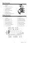
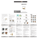
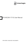
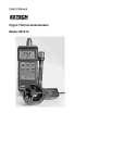
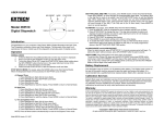
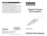
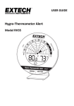
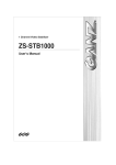
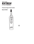
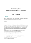
User's Manual
Printing Hygro-Thermometer
Model 445365
Warranty
EXTECH INSTRUMENTS CORPORATION warrants this instrument to be free of defects
in parts and workmanship for one year from date of shipment (a six month limited
warranty applies on sensors and cables). If it should become necessary to return the
instrument for service during or beyond the warranty period, contact the Customer
Service Department at (781) 890-7440 for authorization. A Return Authorization (RA)
number must be issued before any product is returned to Extech. The sender is
responsible for shipping charges, freight, insurance and proper packaging to prevent
damage in transit. This warranty does not apply to defects resulting from action of the
user such as misuse, improper wiring, operation outside of specification, improper
maintenance or repair, or unauthorized modification. Extech specifically disclaims any
implied warranties or merchantability or fitness for a specific purpose and will not be
liable for any direct, indirect, incidental or consequential damages. Extech's total liability
is limited to repair or replacement of the product. The warranty set forth above is
inclusive and no other warranty, whether written or oral, is expressed or implied.
Introduction
Congratulations on your purchase of the Extech 445365 Printing Hygro-Thermometer.
Temperature and humidity or dew point readings can be printed automatically at userdefined intervals. Careful use of this meter will provide years of reliable service.
Specifications
General Specifications
Display
Measurements
Printer
Printing paper
Printing Interval
Sampling rate
Over range indication
Open input indication
Input protection
Low battery indication
Power supply
Battery Life
Operating Temperature
Operating Humidity
Storage Temperature
Dimensions
Weight
Accessories
Triple line multi-function LCD
Temperature (T1 and T2) and Relative Humidity or Dew Point
Thermo printer, 16 characters per line
1.5" (38mm) width plain thermo paper
6 seconds up to 60 minutes (user-selectable)
1 Measurement per second approx.
"OL" appears on the LCD
All dashes display "-------"
60V DC / 24V AC rms
Low battery icon 'BT' appears on the LCD
Six 1.5V AA Batteries (optional AC adapter: 9V/500mA min.)
Approx. 30 hours with printing interval set to 60 mins.;
Approx. 60 hours with printer OFF.
o
o
32 to 122 F (0 to 50 C)
< 95% RH
o
o
14 to 140 F (-10 to 60 C)
7.6 x 2.9 x 1.3" (193 x 74 x 37mm)
Approx. 15.2 oz. (430g) with batteries and paper
Carrying case, batteries, two rolls of thermo paper,
temperature/RH probe (T1), and type K sensor (T2)
Range Specifications
Function
Range
Resolution Accuracy
RH
10 to 95%
0.1%
± 3% RH (30 to 95%)
o
o
o
o
o
Dew Point
-47 to 137 F (-44 to 58 C)
0.1
±1.5 F(0.8 C)
o
o
o
o
o
Temperature
-4 to 140 F (-20 to 60 C)
0.1
±1.5 F(0.8 C)
(Probe T1)
o
o
o
o
o
o
0.1 (<999 ) ±(0.2% rdg +3 F/1.8 C)
Temperature
-328 to -58 F(-200 to -50 C)
o
o
o
o
o
o
(Type k T2)
-58 to 1000 F(-50 to 500 C)
1 (>999 )
±(0.1% rdg +1.6 F/0.8 C)
o
o
o
o
1000 to 2431 F(500 to 1333 C)
±(0.2% rdg +3 F/1.8 C)
o
Temperature Coefficient: 0.1 times the applicable accuracy specification per C from 0 to
o
o
o
o
18 C and 28 to 50 C (32 to 64 F and 82 to 122 F)
2
445365 V1.1 4/01
Meter Description
1.
LCD display
2.
Keypad
3.
Calibration potentiometers (2)
4.
T1 Temp/RH probe input
5.
Thermo print paper
6.
Battery compartment (rear)
7.
Temp/RH Probe
8.
AC Adapter input jack
9.
T2 Type K thermocouple input jack
4
5
1
6
2
8
3
7
Display Description
1.
Dew Point is displayed
10. Decimal point
2.
Low Battery
11. Temperature units
3.
Negative temperature sign
12. Humidity unit of measure
4.
Meter is printing
13. MIN measurement display
5.
Interval printing START time
14. MAX measurement display
6.
Interval printing STOP time
15. Data Hold mode active
7.
Calendar time is displayed
16. Humidity or Dew Pt display
8.
Interval printing time displayed
17. T2 measurement field
9.
T1 measurement field
18. Interval printing is active
3
445365 V1.1 4/01
Meter Operation
Connecting the sensors
1.
This meter accepts two types of input sensors: T1 (left side) accepts the supplied
Temperature/RH probe with the coiled cord and the USB style connector; T2 (right
side) accepts a Type K thermocouple via a standard spade lug thermocouple
connector (sub-miniature type with one spade lug wider than the other).
2.
Plug the sensor(s) into the meter's T1 and/or T2 input jack(s).
Powering the meter
1.
This meter operates on six 1.5V 'AA' batteries (rear battery compartment) or by the
optional AC adapter (9V / 500mA min.) that connects to the meter's lower left side.
2.
Press the green power button to turn ON the meter after the batteries or AC
adapter have been installed. The meter will perform a short self-test during which
the date and the time will briefly appear on the LCD display.
3.
If a probe is not inserted to the meter or the probe is malfunctioning, all dashes "-----" will appear on the Main, T1, and/or T2 LCD display areas. Connect a probe if
one is not connected or try another probe if it appears that the connected probe is
malfunctioning.
Installing Thermo Print Paper
1.
Turn the meter OFF with the green power button and remove all
sensors from the input jacks at the top of the meter.
2.
Open the printer paper compartment using a small coin or screwdriver
in the slot at the top of the meter.
3.
Pull open the compartment and install the paper as shown at right so
that it feeds through the slot on the front of the meter above the clear
plastic feeder.
4.
Close the paper compartment and use the FEED button to advance the
paper.
o
o
Selecting C/ F units of measure
o
o
Press the C/ F key to select the desired units of measure. The display will reflect the
selection.
Relative Humidity %, Temperature and Dew Point Displays
Relative Humidity (RH%): The large digits at the center of the LCD represent the
humidity sensed by the T1 Probe (unless the DEW PT button is pressed).
Dew Point: When the DEW PT button is pressed the large digits at the center of the LCD
display the dew point temperature sensed by the T1 Probe.
Temperature T1: The left lower sub-display represents the temperature measured by the
Temp/RH probe.
Temperature T2: The lower right sub-display represents the temperature measured by
the Type K thermocouple.
Open Input: If the T1 or T2 input jacks are not used, all dashes will appear on their
respective display areas on the LCD.
Over Range: For out of range inputs to the meter, 'OL' will display in the appropriate
field.
4
445365 V1.1 4/01
Programming the Meter
Press the MENU button momentarily to enter the programming mode. The underlined
parameters listed below will appear one by one with each press of the MENU button.
Digits or words in a field will flash when ready to be edited. Use the Right/ Left arrow
keys to move through the various programming fields (if there are more than one for a
given parameter). Use the Up/Down arrow keys to change a particular parameter that is
flashing.
PRINT FUNCTION (ON or OFF); Enables/Disables automatic interval printing
PRINTING INTERVAL (Two fields to program: Minutes & Seconds)
PRINT START TIME (Two fields to program: Hours & Minutes)
PRINT STOP TIME (Two fields to program: Hours & Minutes)
CALENDAR: (Five fields to program: Current Year (last two digits); Month (two
digits); Day (1 to 31); Hour (1 to 24), and Minute (1 to 59)
These parameters are explained in detail in the next sections. Press the MENU button
again to return meter to normal operation.
Setting the Automatic Print Interval
1.
Press the MENU button momentarily to enter the programming mode
2.
Set the PRINT FUNCTION parameter to ON using the Up/Down arrow keys
3.
Press the MENU key to move to the next parameter PRINTING INTERVAL. Set the
amount of time you wish to pass between automatic printouts using the Up/Down
arrow keys; Use the Right/Left arrow keys to toggle between minutes and seconds.
The minimum interval time is 00:06 (6 seconds) and the maximum is 59:59 (59
minutes, 59 seconds).
4.
Press the MENU key to move to the next parameter PRINTING START TIME. Set
the Hour and Minute when printing will begin. The range for START and STOP
times is 00:00 to 23:59 (hours and minutes). Use the Up/Down/Right/Left arrow
keys as previously described.
Note: Print START and STOP times represent a window of time where
automatic printing will occur at the intervals programmed above.
5.
Press the MENU key to access the PRINT STOP TIME parameter. Use the
Up/Down/Right/Left arrow keys as previously described to set the Hour and Minute.
6.
Press the MENU key to exit the programming mode, the left corner of the LCD will
show the clock icon indicating that interval printing is active. Note that the STOP
time cannot be earlier than the START.
Printing Modes
For a one-time printout of the current status of the meter's LCD display, press the
PRINT button momentarily. The printer icon will appear on the left side of the LCD and
four lines with the following format will print on the thermo paper:
Line 1: Date and Time of print
Line 2: Relative Humidity or Dew Point Temperature measurement
Line 3: Temperature of T1 (coiled RH/Temp probe input)
Line 4: Temperature of T2 (Type K thermocouple input)
For automatic printing, set the PRINT FUNCTION to ON as described in the above
section 'Setting the Automatic Print Interval'. The meter will automatically print at the
interval programmed by the user as previously described. The interval time will print
above the data on the first of the automatic printouts. To disable automatic printing, set
the PRINT FUNCTION parameter to OFF in the programming mode.
5
445365 V1.1 4/01
The FEED Button
Press the FEED button to advance the printer paper one line. The FEED button is useful
for advancing the paper when installing a new paper roll.
Setting the Calendar Clock
1.
Press the MENU key five times in succession. The last two digits of the Year field
will be flashing on the LCD. Use the Up/Down arrow keys to set the current year
2.
Press the Right arrow key to move through the current Month, Day, Hours, and
Minutes fields using the Up/Down arrow keys to change each setting.
3.
Press the MENU key again when complete to return to normal meter operation.
MAX-MIN Function
To view the lowest (MIN) and highest (MAX) readings since the meter was powered:
1.
Press the MAX MIN button. The MAX icon will appear along with the highest
readings.
2.
Press the MAX MIN button again to view the lowest readings (along with the MIN
icon). Press the MAX MIN button again to exit the MIN MAX mode.
3.
To clear the MIN MAX meter memory, turn the meter OFF and then back ON again
using the green power ON/OFF button.
Data Hold
To freeze the LCD display, momentarily press the HOLD button. The 'H' hold icon will
appear on the LCD top. Press the HOLD button again to return to normal operation (the
'H' hold icon will disappear).
Battery Replacement
When the BT (low battery) icon appears on the left side of the LCD, it is nearing the
time when the six 'AA' batteries must be replaced. Several hours of use can still be
obtained from the meter after the low battery indication. To replace the batteries:
1.
Remove the screw at the center of the instrument's back and remove the battery
compartment cover.
2.
Replace the six 'AA' batteries observing proper polarity.
3.
Replace the battery compartment cover and secure the screw.
Calibration and Repair Services
Extech offers complete repair and calibration services for all of the products we sell.
For periodic calibration, NIST certification or repair of any Extech product, call customer
service for details on services available. Extech recommends that calibration be performed
on an annual basis to insure calibration integrity.
Tech Support Hotlines
781-890-7440 ext. 200
[email protected]
www.extech.com
Copyright © 2001 Extech Instruments Corporation. All rights reserved including
the right of reproduction in whole or in part in any form.
6
445365 V1.1 4/01