1
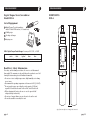
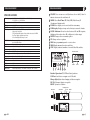
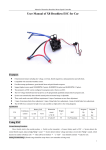
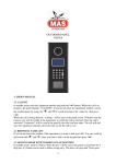
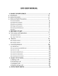
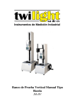
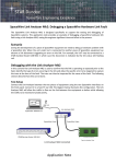
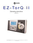
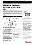
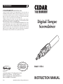
TORQUE MEASUREMENT
2 YEAR WARRANTY
(RESTRICTIONS APPLY)
Imada, Inc. warrants its products to the original purchaser to be free from defects in
workmanship and material under normal use and proper maintenance for two years (one
year for adapters, attachments, batteries, and cables) from original purchase. This warranty
shall not be effective if the product has been subject to overload, shock load, misuse,
negligence, accident or repairs attempted by others than Imada, Inc.
During the warranty period, we will, at our option, either repair or replace defective
products. Please call our customer service department for a return authorization number
and return the defective product to us with freight prepaid.
The foregoing warranty constitutes the SOLE AND EXCLUSIVE WARRANTY, and we hereby
disclaim all other warranties, express, statutory or implied, applicable to the products and/or
software, including but not limited to all implied warranties of merchantability, fitness, noninfringement, results, accuracy, security and freedom from computer virus. In no event shall
Imada, Inc. and/or its affiliated companies be liable for any incidental, consequential or
punitive damages in connection with the use of its products and/or software.
Complete color
catalog available.
Call 800-373-9989
or E-mail us.
Imada, Inc.®
3100 Dundee Rd., Suite 707, Northbrook, IL 60062 USA
Telephone: (847) 562-0834 Fax: (847) 562-0839
Web Site: www.imada.com E-mail: [email protected]
ISO 9001 & ISO/IEC 17025 Accredited
03/09
Specifications subject to change without notice.
Digital Torque
Screwdriver
Model: DID-4
INSTRUCTION MANUAL
TORQUE MEASUREMENT
TORQUE MEASUREMENT
Digital Torque Tester/Screwdriver
Model DID-4
List of Equipment
1
2
3
4
DIMENSIONS
DID-4
1
DIgital Torque Tester/Screwdriver
with CW and CCW ratchet (¼" female hex)
2 Phillips tips
AC adapter/charger
Carrying case
2
4
3
DID-4 Digital Torque Tester Ranges Accuracy ± 0.5% F.S., ±1 LSD
DID-4
ozf-in
2.0~560.0
Capacity
lbf-in
kgf-cm
N-cm
0.20~35.00 0.20~40.00 2.0~400.0
N-m
0.2~4.000
Read First: Safety Information
For safety, and for damage avoidance, be sure to read this manual
thoroughly. The warranty is only valid when the product is used following the instructions provided within this manual.
● Do not use tester in high temperature, high humidity, or in damp
or wet areas.
● Recommended operating temperature is between 0-42ºC (32-100ºF).
● Do not apply torque exceeding the rated capacity (35 lbf-in),
regardless of whether the unit is On or Off. Avoid shock load.
● When charging the battery, be sure to use the provided AC
adapter/charger exclusively.
● Do not use lacquer thinner or any solvent to clean the unit.
● Do not disassemble or modify the unit.
Specifications subject to change without notice
page 2
page 11
TORQUE MEASUREMENT
SPECIFICATIONS
Measuring range
Accuracy
Display
Operation
Measuring modes
GO/NO GO testing
Statistics
Data transfer
Data memory
Batch Counter
Power supply
Auto power save
Charging time
Working time
Bit size
Weight
Accessories
2.0~560.0 ozf-in 0.20~35.00 lbf-in 0.20~40.00 kgf-cm
2.0~400.0 N-cm 0.2~4.000 N-m
± 0.5% F.S., ±1 LSD
4 digit LCD
CW, CCW and fixed position
PP: Peak Mode displays PEAK torque value that will not change until a
higher value is measured.
PD: Peak Down Mode Captures first peak down value above the PDLO
Real Time: Displays transient torque values
C: Real-time Output 180 data per second
Programmable High and Low setpoints with both audible beep and
Green/Red LED indicator
Number of data, maximum, minimum and average
ASCII, 19200 bps, USB miniB cable
800 data
1-99 (CW only)
Ni-Cad rechargeable batteries 1.2V×4cells 600mAh
Automatic switch off after 10 minutes of non-use
From empty - less than 5hours
12 hours continuous use
6.35mm
430g
AC/DC Adapter/Charger, 100~230VAC, 2 Phillips bits, NIST certificate
TORQUE MEASUREMENT
1
2
3
4
5
6
7
8
9
10
ON/OFF Press to turn on or off (click once, do not hold). After 10
minutes of non-use the unit shuts off.
MODE Select Real Time, PP (Peak), PD (Peak Down), C
(Continuous Output mode)
CLEAR Reset display to zero and send data to memory
LCD display Displays torque value, battery icon, mode & units.
GO/NG Indicator Green for values between LO and HI setpoints,
flashing red for values above HI, solid green for data output
DOWN Change values or numeric places
UP Change values or options
PRG Enter programming mode or enter values
MEM Display memory locations and data
STAT Display statistics; number of records, Max, Min, and Ave
BATTERY ICON
5
10
4
9
MODE
1
6
7
8
2
STATS
UNITS
3
Ratchet Operation CW, CCW and fixed positions
USB Port Send data to computer via USB cable
Charge light lights when charging, off when complete.
DC IN AC charger/adapter receptacle
RESET System reset button
CHARGE LIGHT
RATCHET
page 10
USB PORT
DC IN
RESET
page 3
TORQUE MEASUREMENT
GENERAL OPERATION
1. Press and hold MODE for one second to select from the following Measuring Modes.
Real Time–Displays torque transients (no output or indicator)
PP Mode– Peak, captures peak torque (peak data output, PP
appears on the display)
PD Mode– First Peak, capture first peak value (peak data
output, PD appears on the display)
C Mode– Continuous RS-232 output Display and output
torque transients (180 data/sec., C appears on
the display)
2. Insert Phillips tip into the screwdriver.
3. To select ratchet operation turn the ratchet one
click clockwise or counter-clockwise from the
center position. To disable ratcheting, turn it so
the semi circle is in the center position.
4. Press the CLEAR button on the display unit to
zero the display. Insert the screwdriver tip into
the screw, hold perpendicularly (not at an
angle), and turn to measure.
5. After measuring, press CLEAR to zero the display for the next test.
PROGRAMMING
Press POWER to turn on. Press PRG for one second. The display
shows, "HI" and then the High setpoint value. This confirms the
tester is ready for the following programming steps.
TORQUE MEASUREMENT
Output is available in PD, PP and C modes. In PD and PP modes peak
data is output when ZERO is pressed or activated by the AUTO ZERO
function. In C mode, the gauge outputs data continuously 160
data/second.
Comport signal
8 data, 2 stop, no parity. Baud Rate: 19,200 bps.
Output Connector
USB A/B cable
Peak Data Output Format
[CAN] _ _ _ [SO] [value] _ [SI] [unit] [CR]
(_ _ _ is memory location)
[CAN]:
ASCII control code 24
_:
Space (code 32)
[SO]:
ASCII control code 14
[value]:
Output data with sign and decimal point. Plus sign
represents for CW torque and minus sign for CCW.
[Value] always occupy six locations and empty
locations will be filled with spaces.
[SI]:
ASCII control code 15
[unit]:
N*m _ _ _=N.m
kgf*cm = kg.cm
lb*in _ = lb.in
[CR]:
ASCII control code 13 (Carriage Return)
Continuous Output Data Format
[CAN] [value] [CR]
1. High Setpoint (HI)
After "HI" is displayed and the High setpoint
value, press DOWN 6 to move the numeric
place and press UP 7 to select values i.e. 50.0
for 50.0 lbf-in, then press PRG 8 to enter.
2. Low Setpoint (LO)
After High value is entered, "LO" is displayed,
then the Low setpoint value. Press DOWN to
move the numeric place and press the UP to
select values, then press PRG to enter.
page 4
page 9
TORQUE MEASUREMENT
OUTPUT
USB Virtual COM Port
When the tester is connected to a computer’s
USB port and turned on,
Windows XP or Vista will
recognize the tester and
ask to connect to the
Internet. Allow Windows
Update to connect to the
Internet and follow the
instructions on your screen
to download and install
two drivers for the USB virtual com port. For Windows 98, ME and
MAC go to www.ftdichip.com/Drivers/VCP.htm.
The PC and tester will communicate through the USB port the
same as a com port. To verify the
COM port number open the
Device Manager.
page 8
TORQUE MEASUREMENT
3. Peak Down Minimum (PdLO)
After Low value is entered, "PdLO" is displayed, then the PdLO
value. Press DOWN to move the numeric place and press the UP
to select values, then press PRG to enter.
PdLO sets a minimum torque value for Peak Down mode. For
example, if "PdLO" value is set at 5.0 lbf-in, only a reading over
5.0 lbf-in will be measured in Peak Down mode.
4. Continuous Data Output Minimum (CLO)
After Peak Down value is entered, "CLO" is displayed, then the
CLO value. Press DOWN to move the numeric place and press
the UP to select values, then press PRG to enter.
CLO sets the start and stop trigger points for Continuous data
output. When torque reaches the CLO value, the tester starts to
output data and stops if torque falls below the value. Note: the
display does not show any value below the CLO minimum.
5. Auto Zero Reset (AC)
After Continuous Data Output Minimum is entered, "AC" is displayed, then the Auto Zero Reset duration value. Press UP or
DOWN to select 0.0C - 0.1C - 0.5C - 1.0C - 1.5C - 2.0C - 2.5C 3.0C, and press PRG to enter (0.1C for 0.1 second and 0.0C for
MANUAL RESET).
After measuring, Auto Zero automatically resets the tester to "0.0".
6. Batch Counter (CO)
After the Auto Zero value is entered, "CO" is displayed, then the
CO value. Use the UP or DOWN keys to select a value and press
PRG to enter (0-99, clockwise only).
7. Interval (In)
After the Batch Counter value is enetered, "In" is displayed, then
the In value. Use the UP or DOWN keys to select a value and
press PRG to enter (0-24 seconds in 2 second increments).
8. Beeper (bp)
After Interval value is entered, "bp" is displayed, then "On". Press
UP or DOWN to select On, OFF, or FF, then press PRG to enter.
"On"– beeper sounds for Good, NG and capacity overload
"OFF"– beeper sounds for capacity overload only
"FF"– beeper sounds for NG and capacity overload.
page 5
TORQUE MEASUREMENT
9. Units (Un)
After the Beeper is programmed, "Un" is displayed, then the current
unit selection. Press UP to cycle the units; lbf-in, ozf-in, kgf-cm,
N-m and N-cm.
After Units are entered, "-S-" is displayed to confirm programming
completion and zero is shown.
After High and Low setpoints are set and beeper is set to On,
In PP mode
Under LO setpoint– No LED light or beep
Over LO– Green LED lights
Over HI– Red LED flashes and beep sounds
In PD mode– no indicator or beep for values before Peak
down is sensed.
Under LO setpoint– Red LED flashes and slow beep sounds
Between LO and HI– Green LED lights and constant tone sounds
Over HI– Red LED flashes and fast beep sounds
In Real Time and C mode
Under LO setpoint– no LED light or beep
Between LO and HI– Green LED lights and beep sounds
Over HI– Red LED lights and beep sounds
TORQUE MEASUREMENT
Clearing Data from Memory
Single clear: Press MEM, then press UP or DOWN to move to a
memory location. When the desired memory value is displayed,
press CLR, "CLR" is displayed. Press CLR again to clear the data and
"– – – –" is displayed to confirm deletion.
All clear: Press CLR and hold until the display shows "ALL" then
press CLR again and "– – – –" is displayed to confirm deletion.
Downloading Memory Data
1. Press ON/OFF to turn on.
2. Press MEM and after memory data is displayed press MEM again
and "FA" is displayed. Use UP or DOWN to select the first memory location then press MEM and "LA" is displayed. Use UP or
DOWN to select the last memory location. Press MEM again and
data is sent. While data is output -P- is displayed.
Note: By pressing DOWN switch for more than 1 sec, the download
function can be terminated.
Statistics
Press STATISTICS and the number of data, Max, Min, and Avg are displayed in sequence.
Auto Power Off
To maximize the life of the battery, power automatically shuts off
after 10 minutes of non-use.
Low Battery Indicator
DATA MEMORY
Storing and Recalling Data from Memory
Memory functions work in PP and PD modes. Store up to 800 values in memory.
1. Measure in PP or PD mode, when the display resets by either
Auto Zero or manually pressing CLR, the peak value is stored.
2. To recall a value, press MEM and the last stored memory is displayed. Press UP or DOWN to select a memory location (i.e.
.0.0.1 for first location) and torque value. The display cycles
between memory location and value.
page 6
Battery indicator status shows full, half or needs recharging.
If the battery is empty, power is turned off immediately.
IMPORTANT! Use the provided CEDAR AC adapter/charger
exclusively and plug into the correct AC output. It takes 5 hours to
fully recharge for 12 hours of continuous use. When fully charged,
the charge light goes off.
System Reset
When battery power is completely depleted, the tester may not
work even though it has been recharged. In this case, press the
System Reset Button.
page 7