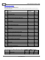
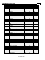
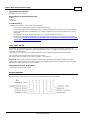
1
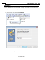
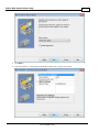
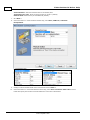
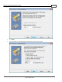
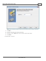
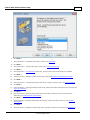
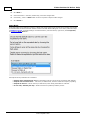
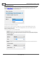
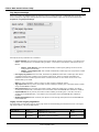
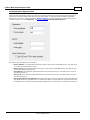
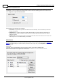
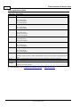
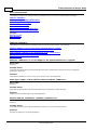
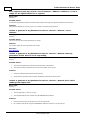
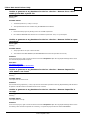
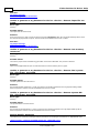
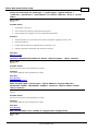
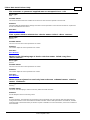
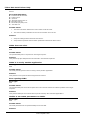
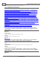
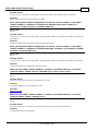
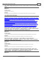
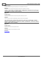
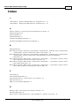
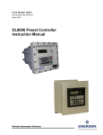
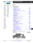
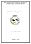
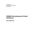
Fisher ROC Serial Driver Help
© 2015 Kepware, Inc.
Fisher ROC Serial Driver Help
2
Table of Contents
Table of Contents
2
Fisher ROC Serial Driver Help
5
Overview
5
Channel Setup
6
Device Setup
12
Scan Mode
14
Timings and Timeouts
15
Automatic Demotion
15
Automatic Tag Database Generation
17
Time Synchronization
18
Tag Import Settings
19
Communication Specification
21
Operator Identification
22
EFM Meters
22
Modem Setup
23
Data Types Description
24
Address Descriptions
25
ROC Point Types
25
Logical / Point Number Details
28
User-Defined Point Types
28
User Table Points
29
Bit Assignments
29
Error Descriptions
30
Address Validation
30
Address <address> is out of range for the specified device or register.
30
Data type <type> is not valid for device address <address>.
30
Device address <address> contains a syntax error.
30
Device address <address> is not supported by model <model name>.
31
Device address <address> is read only.
31
Missing address.
31
Automatic Tag Database Generation Messages
31
Error importing CSV tag record <record number>: Address <Address> is out of range for the
specified device or register.
32
Unable to generate a tag database for device <device>. Reason: <error reason>.
32
Unable to generate a tag database for device <device>. Reason: Auto tag generation failed. Device is
not responding.
32
Unable to generate a tag database for device <device>. Reason: Error while reading from import file. 32
Unable to generate a tag database for device <device>. Reason: Error while reading from ROC system
file.
33
Unable to generate a tag database for device <device>. Reason: Failed to open record set.
33
Unable to generate a tag database for device <device>. Reason: Import file <file name> not found.
33
Unable to generate a tag database for device <device>. Reason: Input file is corrupt.
33
www. kepware.com
Fisher ROC Serial Driver Help
3
Unable to generate a tag database for device <device>. Reason: Input file not found.
34
Unable to generate a tag database for device <device>. Reason: Low memory resources.
34
Unable to generate a tag database for device <device>. Reason: ROC system file <file name> not
found.
34
Unable to generate a tag database for device <device>. Reason: System DB file <file name> not
found.
34
Device-Specific Messages
34
<Device Name> - Failed to read EFM pointer file. <Extended error>.
35
<Device Name> - Failed to write EFM pointer file. <Extended error>.
35
Block read for point type <point type>, logical address <logical address>, parameter range <start
parameter - end parameter> of device <device name> failed. <Error reason>.
36
Device <device> responded with error. (Tag <tag address>)-Details: <error code>.
36
Failed to obtain data block for point type = <point type>, logical address = <address>, Starting
Parameter = <starting parameter>, ending parameter <ending parameter> for device <device>.
Error = <ROC error code>.
36
Failed to write data for point type = <point type>, logical address = <address>, parameter =
<parameter> for device <device>. Error = <error code>.
37
Operator identification failed for device <device name>. <Error reason>.
37
Read for point type <point type>, logical address <logical address>, parameter number <parameter
number> of device <device name> failed. <Error reason>.
37
ROC initialization error: Unable to read general configuration.
37
ROC initialization error: Unable to retrieve I/O map.
38
Serialization of EFM data to temporary file <file name> failed. Reason: <file I/O error>.
38
The username or password supplied was not accepted. Error = 6.
38
The username or password supplied was not accepted. Error = 63.
39
Time synchronization with device <device name> failed. <Error reason>.
39
Write for the following tags of device <device name> failed: <tag list>. <Error reason>.
39
Write request rejected on read only item reference <channel name> <device name> <address>.
39
Device Status Messages
40
Device <device name> is not responding.
40
EFM <type> upload failed for device <device>. <Reason>.
40
Resetting the EFM cache for device <device>.
40
Serial Communications
40
Communications error on <channel name> [<error mask>].
40
COMn does not exist.
41
COMn is in use by another application.
41
Error opening COMn.
41
Unable to set comm parameters on COMn.
41
User Configurable Table Messages
42
Block read for user table <table number>, location range <start location> - <end location> of device
<device name> failed. Device returned error code <error code>.
42
Block read for user table <table number>, location range <start location> - <end location> of device
<device name> failed. Framing error.
42
Block read for user table <table number>, location range <start location> - <end location> of device
<device name> failed. Locations are not configured in the user table.
42
Error parsing user table configuration on device <device name>. User table <table number> contains
an invalid user-defined point type, location, or parameter in table location <location address>.
43
Error parsing user table configuration on device <device name>. User table <table number> contains 43
www. kepware.com
Fisher ROC Serial Driver Help
4
an invalid point type, location, or parameter in table location <location address>.
Read for user table <table number>, location <location address> of device <device name> failed.
Device returned error code <error code>.
43
Read for user table <table number>, location <location address> of device <device name> failed.
Framing error.
43
Read for user table <table number>, location <location address> of device <device name> failed.
Location is not configured in the user table.
44
User table configuration upload on device <device name> failed. Device not responding.
44
User table configuration upload on device <device name> failed. Device responded with error code
<error code>.
44
User table configuration upload on device <device name> failed. Framing error.
44
User table configuration upload on device <device name> failed. Internal error.
45
User-Defined Point Messages
45
Block read for point type <point type>, logical address <logical address>, parameter range <start
parameter - end parameter> of device <device name> failed. Parameters are not in the loaded UDP
configuration.
45
Read for point type <point type>, logical address <logical address>, parameter number
<parameter> of device <device name> failed. Parameter is not in the loaded UDP configuration.
45
Unable to load user-defined point configuration for point type <point type>, logical address <logical
address>, parameter number <parameter> of device <device name>. The number of parameters for
this point is 0.
45
Unable to parse the user-defined point configuration information for point type <point type> on
device <device name>.
46
User-defined point configuration upload for point type <point type>, logical address <logical
address>, parameter number <parameter> of device <device name> failed. <Error reason>.
46
ROC Error Codes
47
Error Reasons
48
Index
49
www. kepware.com
Fisher ROC Serial Driver Help
5
Fisher ROC Serial Driver Help
Help version 1.068
CONTENTS
Overview
What is the Fisher ROC Serial Driver?
Channel Setup
How do I configure channels for use with this driver?
Device Setup
How do I configure a device for use with this driver?
Data Types Description
What data types does this driver support?
Automatic Tag Database Generation
How can tags be automatically created for this driver?
Address Descriptions
How do I address a data location on a Fisher ROC Serial device?
Error Descriptions
What error messages does the Fisher ROC Serial Driver produce?
Overview
The Fisher ROC Serial Driver provides a reliable way to connect Fisher ROC Serial controllers to OPC client
applications, including HMI, SCADA, Historian, MES, ERP, and countless custom applications.
Note: For more information on available Opcodes, Point Types, Parameters, and Opcode 255 Error Codes, refer
to the ROC Protocol User Manual.
Important: EFM functionality is not available in all server versions. To determine whether support is available,
refer to the "Server Summary Information" topic located in the server help file.
Supported Devices
FloBoss 100 Series
FloBoss 407
FloBoss 500 Series
ROC 300 Series-ROCPAC
ROC 300 Series-FlashPAC
RegFlo
Supported Protocol
Remote Operation Controllers (ROC)
Maximum Number of Channels and Devices
The maximum number of supported channels is 256. The maximum number of devices supported per channel is
255.
Ethernet Encapsulation
This driver supports Ethernet Encapsulation, which allows communications with serial devices attached to an
Ethernet network using a Serial-to-Ethernet server. It may be enabled through the Communications tab in
Channel Properties. For more information, refer to "Channel Properties - Ethernet Encapsulation" in the server's
help documentation.
Important: Some FloBoss 100 Series devices (such as FloBoss 107) fail to respond to TCP requests that use
Explicit Congestion Notification (ECN). To communicate with these devices, the global TCP/IP ECN parameter
must be disabled.
Note: This driver does not support Report by Exception.
www. kepware.com
Fisher ROC Serial Driver Help
6
Channel Setup
The Fisher ROC Serial Driver supports Communication Serialization, which specifies whether data transmissions
should be limited to one channel at a time. For more information, refer to "Channel Properties - Advanced" in the
server help file. The maximum number of supported channels is 256.
To create a new channel:
1. In the Project View, right-click and choose New Channel.
2. Accept the default channel name or enter a name for the new channel.
3. Click Next >.
4. From the Device Driver drop-down, select Fisher ROC Serial.
www. kepware.com
Fisher ROC Serial Driver Help
7
5. Click Next >.
6. In the New Channel - Communication Serialization wizard step, configure the channel.
www. kepware.com
Fisher ROC Serial Driver Help
8
Virtual Network - Select the network name or the default, None
Transactions per cycle - Enter the target number or accept 1 (default).
Network Mode -Select Priority or Load Balanced (default).
7. Click Next >.
8. In the New Channel - Communications wizard step, select None, COM Port,or Ethernet
Encapsulation.
9. Configure communication based on the environment and click Next >.
10. In the New Channel - Connection Behavior wizard step, select Close connection when idle to reduce
traffic and specify the number of seconds before the connection is terminated.
www. kepware.com
Fisher ROC Serial Driver Help
9
11. Click Next >.
12. In the New Channel - Write Optimizations wizard step, configure channel writes.
www. kepware.com
Fisher ROC Serial Driver Help
10
Optimization Method - Accept the default or change the selection by clicking in a radio button.
l
Write all values for all tags (most data, most network traffic)
l
Write only the latest value for non-Boolean tags (least data, least network traffic)
l
Write only the latest value for all tags (key data, moderate network traffic)
Duty Cycle - Accept 10 (default) writes for every 1 read or adjust using the up/down arrows. The range
is 1-10.
13. Click Next >.
14. In the New Channel - Non-Normalized Float Handling wizard step, configure how non-normalized values
will be handled.
Replaced with zero recognizes invalid outliers and eliminates them by replacing the value with integer
zero (default).
Unmodified allows values that are potentially invalid outliers into the data stream.
15. Click Next >.
16. In the New Channel - Inter-Device Delay wizard step, configure the time, in milliseconds, between
requests to devices.
www. kepware.com
Fisher ROC Serial Driver Help
11
Delay Accept 0 milliseconds (default) or adjust using the up/down arrows. The range is 0-60000 ms.
17. Click Next >.
18. Review the configuration in the Summary wizard step.
19. If necessary, use the < Back button to return to previous steps to make changes.
20. Click Finish >.
See "Modem Setup " on page 23
www. kepware.com
Fisher ROC Serial Driver Help
12
Device Setup
Once at least one channel is configured, devices using the Remote Operation Controllers (ROC) protocol can be
added for data collection and monitoring. The maximum number of devices supported on any one channel is 255.
Devices should be added to channels organized based on the channel configuration.
Adding a Device
To add a new device to a channel:
1. In the Project View, select the channel to contain the new device.
2. Select Click to add a device or right-click and choose New Device.
3. In the New Device - Name wizard step, accept the default channel name or enter a name for the new
device.
4. Click Next >.
5. From the Device Model drop-down, select the correct model for the device.
www. kepware.com
Fisher ROC Serial Driver Help
13
6. Click Next >.
7. In the New Device - Scan Mode wizard step, configure the Scan Mode.
8. Click Next >.
9. In the New Device - Timing wizard step, configure the Timeouts and Timing.
10. Click Next >.
11. In the New Device - Auto-Demotion wizard step, configure how communication failure is handled.
12. Click Next >.
13. In the New Device - Database Creation wizard step, configure Automatic Tag Database Generation.
14. Click Next >.
15. In the New Device - Time Synchronization wizard step, configure timezone, DST, and synchronization.
16. Click Next >.
17. In the New Device - Tag Import Settings wizard step, identify and locate existing files to be included (see
Tag Import Settings)
18. Click Next >.
19. In the New Device - Communication Specification wizard step, identify the source and destination
addresses (see Communication Specification).
20. Click Next >.
21. In the New Device - Operator Identification wizard step, configure the authorized user (see Operator
Identification).
22. Click Next >.
23. In the New Device - EFM Meters wizard step, add or update the meters for this device (see EFM Meters).
www. kepware.com
Fisher ROC Serial Driver Help
14
24. Click Next >.
25. In the New Device - Summary wizard step, review the configuration.
26. If necessary, use the < Back button to return to previous steps to make changes.
27. Click Finish >.
Scan Mode
Scan Mode settings are defined as a device is added and configured through the New Device wizard and can also
be modified after the device has been added. To define the Scan Mode settings for a new device, follow the steps
for Adding a Device. To modify settings on a defined device; select the device, right-click, select Properties,
and select the Scan Mode tab.
Descriptions of the parameters are as follows:
l
Respect client specified scan rate uses the polling frequency of the client requesting data (default).
l
Request data no faster than... sets a time, in milliseconds, to be the maximum frequency of polling.
l
Request all data at... sets an interval, in millisecond, when all tag information is collected.
l
Do not scan, demand poll only... allows a device to be polled by another process.
www. kepware.com
Fisher ROC Serial Driver Help
15
Timings and Timeouts
Timings and Timeouts settings are defined as a device is added and configured through the New Device wizard
and can also be modified after the device has been added. To define the Timings and Timeout settings for a new
device, follow the steps for Adding a Device. To modify settings on a defined device; select the device, rightclick, select Properties, and select the Timing tab.
Descriptions of the parameters are as follows:
l
l
l
l
Connect timeout specifies the number of seconds before the server determines the connection has
failed. The default is 3 seconds.
Request timeout specifies the number of milliseconds before the server determines the a single poll
failed. The default is 3000 milliseconds.
Fail after specifies the number of consecutive attempts are considered a failed connection. The default is
3 successive timeouts.
Inter-request delay specifies the number of milliseconds between poll attempts. The default is 0
milliseconds.
Automatic Demotion
Automatic Demotion settings are defined as a device is added and configured through the New Device wizard and
can also be modified after the device has been added. To define the Scan Mode for a new device, follow the steps
for Adding a Device. To modify settings on a defined device; select the device, right-click, select Properties
and select the Auto-Demotion tab.
www. kepware.com
Fisher ROC Serial Driver Help
16
Descriptions of the parameters are as follows:
l
l
l
l
Enable auto device demotion on communication failure - Allows communication to bypass a nonresponsive device and attempt data collection from other devices.
Demote after (n) successive failures - Defines the number of failed attempts at communication
before a device is bypassed. The default is 3.
Demote for (n) milliseconds - Configures the time, in milliseconds, the demoted device is bypassed to
allow other communication to occur. Once the delay expires, attempts to communicate with the device
resume. The default is 10000 milliseconds.
Discard write requests during the demotion period - Allows requests to be removed, rather than
queued, while the device is non-responsive and demoted.
www. kepware.com
Fisher ROC Serial Driver Help
17
Automatic Tag Database Generation
This driver supports the server's Automatic Tag Database Generation feature. When enabled, a list of tags is built
within the server that correspond to the device's data points. Extra tags may be generated that affect the quality
of other generated tags. To configure Automatic Tag Database Generation settings, locate the Database Creation
tab in device properties.
Note: For information on importing tags from a ROCLINK project, refer to Tag Import Settings.
www. kepware.com
Fisher ROC Serial Driver Help
18
Time Synchronization
Time Synchronization settings are defined as a device is added and configured through the New Device wizard
and can also be modified after the device has been added. To define the Scan Mode for a new device, follow the
steps for Adding a Device. To modify settings on a defined device; select the device, right-click, select
Properties, and select the Time Synchronization tab.
Descriptions of the parameters are as follows:
Select the time zone in which the device is installed. This is used for the data timestamps from the device.
If the environment (servers, devices, clients) adjust for Daylight Saving Time, click to enable the option to
Respect Daylight Saving Time.
There are three options for Synchronization Method:
l
l
l
Disabled allows device, client, and server times to be fully independent (default).
Absolute establishes a precise daily time when clocks in the environment (servers, devices, clients) are
forced to the same time. This allows data correlation by timestamp. Use the up/down buttons to specify if
the synchronization time.
Interval establishes a recurring synchronization of the environment clocks every specified number of
minutes.
www. kepware.com
Fisher ROC Serial Driver Help
19
Tag Import Settings
Users can create a tag database based on either the device's configuration file or a ROCLINK 800 project file. To
view or change the Tag Import settings after the device has been added, right-click on the device and select
Properties | Tag Import Settings.
Descriptions of the parameters are as follows:
l
Import method: This parameter specifies the import method. Options include Online - from Device and
Offline - from Import File. The default setting is Online - from Device. Descriptions of the options are as
follows:
l
l
l
Online - From Device: This method automatically creates tags by polling the device for its
configuration and I/O data.
Offline - From Import File: This method automatically creates tags from a project file created
in ROCLINK 800.
Use legacy tag names: When checked, Automatic Tag Database Generation creates tags with names
consistent with the tags created in prior versions of the server. When unchecked, Automatic Tag
Database Generation creates tags with names consistent with the current version of the server. The
default setting is checked.
Note: For more information, refer to "Legacy vs. Non-Legacy Tag Names" below.
l
l
l
l
Tag import file: When pressed, this button invokes a dialog for locating the *.800 file that was created
using the ROCLINK800 software.
ROC system file: When pressed, this button invokes a dialog for locating the *.mdb file. This file is
usually named "ROC.mdb," and resides in the same folder where the ROCLINK 800 software is installed.
System DB file: When pressed, this button invokes a dialog for locating the *.mdw file. This file is
usually named "ROCLINK.mdw," and resides in the same folder where the ROCLINK 800 software is
installed.
Display descriptions: When checked, this option includes the tag descriptions from the ROCLINK 800
master database.
Legacy vs. Non-Legacy Tag Names
For information on how legacy and non-legacy tag names are automatically generated based on the "Use legacy
tag names" option, refer to the table below.
Tag Type
Mode
Tag Name
Tag Address
Non-Boolean
Legacy
Non-Legacy
IPAddress_12_0
IP Address-12 (T12,L0,P1)
12-0.1
12-0.1
Boolean (.Bit)
Legacy
Non-Legacy
HighAlarm_3_0
High Alarm-3 (T3,L0,P16) Bit 2
3-0.16:2
3-0.16:2
www. kepware.com
Fisher ROC Serial Driver Help
20
See Also: Automatic Tag Database Generation
www. kepware.com
Fisher ROC Serial Driver Help
21
Communication Specification
Communication Specification settings are defined as a device is added and configured through the New Device
wizard and can also be modified after the device has been added. To define the Communication Specification
settings for a new device, follow the steps for Adding a Device. To modify settings on a defined device; select
the device, right-click, select Properties, and select the Communication Specification tab.
Descriptions of the parameters are as follows:
l
l
l
l
l
Device address: This parameter specifies the device number of the remote ROC device. The valid range
is 1 to 255. The default setting is 240.
Device group: This parameter specifies the group number of the remote ROC device. The valid range is
1 to 255. The default setting is 240.
Host address: This parameter specifies the ROC unit number of the server. The valid range is 1 to 255.
The default setting is 1.
Host group: This parameter specifies the ROC group number of the server. The valid range is 1 to 255.
The default setting is 1.
Use Opcode 180 for read requests: This option should be used if few parameters from each point type
and logical address are typically used, as it yields more efficient communication. If unchecked, the driver
uses Opcode 167 to read entire point type logical addresses in one transaction. The default is unchecked.
www. kepware.com
Fisher ROC Serial Driver Help
22
Operator Identification
This dialog is used to specify the operator identification values used when logging into the ROC device during
initialization. To view or change these settings after the device has been added, right-click on the device and
select Properties | Operator Identification.
Descriptions of the parameters are as follows:
l
l
l
Username: This parameter specifies the authorized account identity. Three characters (as set in the
device) are required.
Password: When checked, this option specifies that the ROC device has a password defined for the
operator ID. Four numeric characters can be entered. The valid range is 0000 to 9999. The default
setting is checked.
Access Level: When checked, this option specifies that the ROC device has defined access levels. The
valid range is 0 to 5. The default setting is unchecked.
EFM Meters
EFM Meter settings are defined when a device is added and configured through the New Device wizard and can
also be modified at any time. To define the EFM Meter settings for a new device, follow the steps for Adding a
Device. To modify settings on a defined device; select the device, right-click, select Properties, and select the
EFM Meters tab.
Important:
The meter order in the EFM Meter List should match the order of the meters in ROCLINK 800.
Only Hourly and Daily History data may be uploaded from the FloBoss 100 Series and RegFlo devices.
Extended History data is not supported for those devices.
www. kepware.com
Fisher ROC Serial Driver Help
23
Descriptions of the parameters are as follows:
l
l
l
l
l
l
l
l
Non-Meter Events: This parameter specifies how non-meter EFM events are provided to EFM Exporters.
Options include Ignore, Broadcast, and Selected Meters. The default setting is Broadcast. Descriptions of
the options are as follows:
l
Ignore: This option does not send non-meter events for any meters.
l
Broadcast: This option sends non-meter events for all meters.
l
Selected Meters: This option only sends non-meter events for enabled meters.
Meter Count: This parameter displays the number of meters that have been added to the device.
EFM Meter List: This list view displays the meters that are currently supported by the device, including
the meter name and Non-Meter Event configuration.
Note: The # column displays the actual meter number of each configured meter. This is the one-based
meter number that corresponds to the meter numbers the ROCLINK 800 configuration software used to
configure ROC devices.
Add: When clicked, this button opens the Meter Configuration dialog for adding a new meter to the
device.
Remove: When clicked, this button deletes the selected meter from the EFM Meter List.
Modify: When clicked, this button opens the Meter Configuration dialog for updating the selected meter
in the EFM Meter List.
Move Up: When clicked, this button changes the order, moving the selected meter up in the EFM Meter
List.
Move Down: When clicked, this button changes the order, moving the selected meter down in the EFM
Meter List.
Clear Cache on Next Upload
Users have the option to clear any cached EFM data from the device during the next upload. This feature also
removes pointer files, which are used to track EFM uploads to prevent uploading the same records twice. All EFM
data is re-uploaded. Once the cache is cleared, this parameter is automatically disabled. To enable this option,
open Device Properties | EFM Meters and click Clear cache on next upload. The default setting is
unchecked.
Meter Configuration
Descriptions of the parameters are as follows:
l
l
Meter Name: This parameter specifies the meter name. Each meter must be assigned a unique name.
The default setting is Meter_1.
Receive Non-Meter Events: When checked, this option enables the meter to receive non-meter events.
Note: This option is only available when the Non-Meter Events parameter is set to Selected Meters.
Modem Setup
This driver supports modem functionality. For more information, please refer to the topic "Modem Support" in the
OPC Server Help documentation.
www. kepware.com
Fisher ROC Serial Driver Help
24
Data Types Description
Data Type
Description
Boolean
Single bit
Char
Signed 8-bit value
bit 0 is the low bit
bit 6 is the high bit
bit 7 is the sign bit
Byte
Unsigned 8-bit value
bit 0 is the low bit
bit 7 is the high bit
Short
Signed 16-bit value
bit 0 is the low bit
bit 14 is the high bit
bit 15 is the sign bit Word
Unsigned 16-bit value
bit 0 is the low bit
bit 15 is the high bit DWord
Unsigned 32-bit value
bit 0 is the low bit
bit 31 is the high bit
Float
32-bit floating point value
bit 0 is the low bit
bit 31 is the high bit
TLP
32-bit value
Point type: Logical or point number and parameter number use three bytes. The top byte is not
used.
String
A linear group of ASCII characters with preserved whitespace (1 byte per character).
Date
64-bit floating point value
Date
Example
Date format:YYYY-MM-DDTHH:MM:SS.000
2000-01-01T12:30:45.000
For more information, refer to Logical Point Number Details and ROC Point Types.
www. kepware.com
Fisher ROC Serial Driver Help
25
Address Descriptions
ROC addresses are divided first by point type, logical address, and then by parameter index within the point type.
The general format is T-L.P, where:
l
T: The Point Type
l
L: The Logical Address
l
P: The Parameter Index
Parameters are blocked together on point type and logical address to a size up to 236 bytes. Some parameters are
broken down into individual bits. Those parameters are addressed as T-L.P:B, where:
l
B: The Bit Offset
For example, the address 1-50.3:2 indicates the following:
l
Point Type: 1
l
Logical Address: 50
l
Parameter: 3
l
Bit Offset: 2
For a detailed listing of all point type parameters, access, data type, length, and description, refer to the ROC
device's ROC Protocol User Manual. For more information on ROC addressing, select a link from the list below.
ROC Point Types
Logical / Point Number Details
User-Defined Point Types
Bit Assignments
ROC Point Types
The availability of point types varies by model and by how the particular unit is equipped. Points may be physical
I/O or internal I/O.
Physical I/O Points
Physical I/O points are one of Discrete Inputs (type 1), Discrete Outputs (type 2), Analog Inputs (type 3), Analog
Outputs (type 4), and Pulse Inputs (type 5). The logical address for physical I/O points is based on their position
in the unit, known as point number. There are four slots for each rack. The I/O field is not typically fully
populated.
Note: Rack and slot are ROC nomenclature; however, many ROC devices have no physical racks or slots.
Logical addresses are calculated from the Point Number reference. For information on reconciling the Point
Number to the Logical Address, refer to the table below.
ROCLINK Point Number
Server Logical Address
A1-A16
0-15
B1-B16
16-31
C1-C16
32-47
D1-D16
48-63
E1-E16
64-79
...
...
For example, an I/O point with ROCLINK 800 point number "A5" would be logical address "4". An I/O point with
ROCLINK 800 point number "C5" would be logical address "36" by the function A + B + C5 (or 15+16+5=36).
Internal I/O Points
Internal I/O points consist of PID settings, system flags, communications parameters and other internal
information. The internal I/O logical address begins at 0 for each point type. A ROC unit may have one or several
of a given internal point type. Each point type has a specific set of parameters. ROC drivers have no array types.
Point Type Tables
ROC Point Types for ROC300-Series
ROC Point Types for FloBoss 100-Series, FloBoss 407, and FloBoss 500-Series
www. kepware.com
Fisher ROC Serial Driver Help
26
ROC Point Types for RegFlo
ROC Point Types for ROC300-Series
For a detailed listing of all point type parameters' access, data type, length and description, refer to the device's
ROC Protocol User Manual.
Point
Types
Description
ROC300-Series
FlashPAC
ROC300Series
ROCPAC
0
Configurable Opcode
Yes
Yes
1
Discrete Inputs (DI)
Yes
Yes
2
Discrete Outputs (DO)
Yes
Yes
3
Analog Inputs (AI)
Yes
Yes
4
Analog Outputs (AO)
Yes
Yes
5
Pulse Inputs (PI)
Yes
Yes
6
Proportional, Integral and Derivative (PID) Control
Yes
Yes
7
American Gas Association (AGA) Flow Parameters
Yes
Yes
9
Local Display Panel
Yes
Yes
10
AGA Flow Values
Yes
Yes
11
Tank Parameters
No
Yes
12
ROC Clock
Yes
Yes
13
System Flags
Yes
Yes
14
Communication Ports
Yes
Yes
15
System Variables (ROC Information)
Yes
Yes
16
Function Sequence Table (FST) Parameters
Yes
Yes
17
Soft Points
Yes
Yes
18
AI Calibration
No
Yes
19
Database Setup
Yes
Yes
20
ROC Tasks
Yes
Yes
21
Information for User Defined Points
Yes
Yes
22-31
User Defined Points
No
No
32
User Defined Typically Modem Config for COM1
Yes
Yes
33
User Defined Typically Modem Config for LOI and COM2
Yes
Yes
34
User Defined Typically Modbus Config for COM1
Yes
Yes
35
User Defined Typically Function Config for COM1
Yes
Yes
36
User Defined Typically Host Config for COM1
Yes
Yes
37
User Defined Typically Modbus Config for LOI and COM2
Yes
Yes
38
User Defined Typically Function Config for LOI and COM2
Yes
Yes
39
User Defined Typically Host Config for COM1
Yes
Yes
40
Multi-Variable Sensor (MVS) Parameters
Yes*
No
41
AGA Run Parameters
Yes
No
42
Extra Run Parameters
Yes
No
44
Power Control
Yes
No
49
Upload to Disk
No
No
50
Download to ROC
No
No
56
AI Calibration
Yes
No
57
Keypad / Login Security Parameters
Yes
No
59
Program Flash Control Parameters
Yes
No
*Added via a user program.
ROC Point Types for FloBoss 100-Series, FloBoss 407, and FloBoss 500-Series
Point Types
Description
FloBoss
100-Series
FloBoss
407-Series
FloBoss
500-Series
0
Configurable Opcode
Yes
Yes
Yes
1
Discrete Inputs
Yes
Yes
Yes
2
Discrete Outputs
Yes
Yes
Yes
www. kepware.com
Fisher ROC Serial Driver Help
27
3
Analog Inputs
Yes
Yes
Yes
4
Analog Outputs
Yes
Yes
Yes
5
Pulse Inputs
Yes
Yes
Yes
6
PID Control*
Yes
Yes
Yes
7
AGA Flow Parameters*
Yes
Yes
Yes
8
History Parameters
Yes
No
Yes
10
AGA Flow Values*
Yes
Yes
Yes
12
ROC Clock
Yes
Yes
Yes
13
System Flags
Yes
Yes
Yes
14
Communication Ports
Yes
Yes
Yes
15
System Variables (ROC Information)
Yes
Yes
Yes
16
FST Parameters
Yes
Yes
Yes
17
Soft Points
Yes
Yes
Yes
19
Database Setup
Yes
Yes
Yes
20
ROC Tasks
Diagnostics
No
Yes
Yes
No
No
No
21
Information for User Defined Points
Yes
Yes
No
22-23
User Defined Points
No
No
No
24
Reserved
N/A
N/A
N/A
25–31
User Defined Points
No
No
No
32
User Defined – Typically Modem Config for
COM1
Yes
Yes
No
33
User Defined – Typically Modem Config for LOI
and COM2
Yes
Yes
No
34
User Defined – Typically Modbus Config for
COM1
Yes
Yes
No
35
User Defined – Typically Function Config for
COM1
Yes
Yes
No
36
User Defined – Typically Host Config for COM1
Yes
Yes
No
37
User Defined – Typically Modbus Config for LOI
and COM2
Yes
Yes
No
38
User Defined: Typically Function Config for LOI
and COM2
Yes
Yes
No
39
User Defined – Typically Host Config for COM1
Yes
Yes
No
40
Multi-Variable Sensor (MVS) Parameters
Yes
Yes
No
41
AGA Run Parameters*
Yes
Yes
Yes
42
Extra Run Parameters*
Yes
Yes
Yes
43
User Lists
Yes
Yes
Yes
44
Power Control
Yes
Yes
Yes
45
Meter Calibration and Sampler
Yes
No
Yes
46
Meter Configuration Parameters
Yes
No
Yes
47
Meter Flow Values
Yes
No
Yes
48
PID Control Parameters
Yes
No
Yes
49
Upload to Disk
No
No
No
50
Download to ROC
No
No
No
52
Battery Parameters
No
No
Yes
53
Modbus Configuration Parameters
Yes
No
Yes
54
Modbus Function Tables
Yes
No
Yes
55
Modbus Special Function Table
Yes
No
Yes
56
AI Calibration
Yes
Yes
Yes
57
Keypad / Login Security Parameters
Yes
Yes
Yes
58
Revision Information
Yes
No
Yes
59
Program Flash Control Parameters
Yes
Yes
Yes
60-77
SAM User Defined Parameters
No
No
No
80
Enhanced Communication (ECM) Parameters
Yes
No
No
85
HART Parameters
Yes
No
No
www. kepware.com
Fisher ROC Serial Driver Help
28
86
Extended History Parameters
Yes
No
No
88
BLM User Lists
Yes
No
No
89
Chart User List Parameters
Yes
No
No
93
License Key Information Parameters
Yes
No
No
94
User C Program Parameters
Yes
No
No
98
Extended Soft Point Parameters
Yes**
No
No
117
Modbus Configuration Parameters
Yes
No
No
118
Modbus Register Mapping Parameters
Yes
No
No
120
Modbus Master Modem Configuration
Yes
No
No
121
Modbus Master Polling Table Configuration
Parameters
Yes
No
No
122
DS800 Configuration Parameters
Yes
No
No
*FloBoss 100-Series and FloBoss 500-Series Backward Compatibility.
**This point type is only supported by FloBoss 107.
ROC Point Types for RegFlo
Point Types
Description
Point Types
Description
0
Configurable Opcode
17
Soft Points
1
Discrete Inputs
19
Database Setup
2
Discrete Outputs
56
AI Calibration
3
Analog Inputs
57
Keypad / Login Parameters
4
Analog Outputs
80
Regulator Parameters
8
History Parameters
81
Logic Alarm Parameters
13
System Flags
84
User Discrete Values
14
Communication Ports
86
Extended History Parameters
15
System Variables N/A
N/A
Logical / Point Number Details
Within each point type, individual points are referenced by a logical number or a point number. The point
numbers used by the ROC protocol for point types 1 to 5 are based on a physical input or output (I/O) with a rack
and module location. All other point types use a logical number and are numbered in sequence.
Physical Point Numbers 0 to 69
For point types 1 through 5, there are point numbers for the field I/O and for the diagnostic inputs. They are as
follows:
l
l
Point numbers 0 to 63 are assigned to field I/O (built-in or modular, 64 maximum). For example, if there
were ten I/O modules in a ROC364, they would be points 0 through 9. The ROC I/O point database would
reference these points by rack and module location, such as A1 through A10.
Point numbers 64 to 69 are assigned to the diagnostic (system) I/O. For example, the five diagnostic
points in a ROC364 would be 64 through 68. The ROC I/O point database would reference these points by
rack and module (namely, E1 to E5).
Logical Point Numbers 0 to 127
For all other point types (0 and 6–59), the point number is 0 to x, where x is one less than the total number of
points that exist for that point type. For example, the four MVS points in a FloBoss 407 would be logical numbers
0 through 3.
Note: All parameters are 0-based for each point type.
User-Defined Point Types
User-Defined Points (UDP) make user program data available to ROCLINK and OPC clients. They are generally
used for configuration purposes. When creating a UDP in the server, the server Configuration always sets the
data type to default. The data type is later read live from the device.
Important: Users must reinitialize the server after upgrading the user program on a device; otherwise, the
server cannot access the new points available in the upgraded user program.
www. kepware.com
Fisher ROC Serial Driver Help
29
Supported Device Models
All FloBoss 100 Series devices.
Supported User-Defined Point Range
22 to 23
25 to 39
178 to 189
Troubleshooting
To avoid potential issues, users should do the following:
l
l
l
l
Verify that the point type is within the supported UDP range.
If a client attempts to write to a UDP type when no UDP type tags have been read since the server started,
the write may fail with a Type Mismatch error. Always complete a read on UDP type tags before a write is
attempted.
Verify that the point type exists in one of the user programs installed on the device.
Check the Event Log for the following error message, which occurs if the server fails to parse the UDP
configuration: Unable to parse the user-defined point configuration information for point type
<point type> on device <device name>.
User Table Points
User tables, also called Opcode tables, provide the ability to map any Point Type parameters to tables in the
device. This driver has the ability to read and write data points in the user tables using Opcodes 10 and 11. The
syntax for user table tags is:
user_table-n.m where n is the user table number and m is the data point or location within that table.
The user table number and location number are zero-based.
For example, the first location in the first user table is: user_table-0.0.
Important: Users must increment the version number of the user table when making changes to the table
configuration. Failure to do so when making changes to the table while the server is actively reading user table
tags results in bad quality tags or erroneous data.
Supported User Table Point Range
user_table-0.0 to user_table-15.43
Bit Assignments
The graphic below shows a sample bit assignment. The bits in each byte are numbered 0 to 7, right to left, with
Bit 7 shown the furthest to the left. A 1 in any bit indicates that it is active or enabled.
www. kepware.com
Fisher ROC Serial Driver Help
30
Error Descriptions
The following categories of messages may be generated. Click on a link to see a list of related messages.
Address Validation
Automatic Tag Database Generation
Device-Specific Messages
Device Status Messages
Serial Communications
User Configurable Table Messages
User-Defined Point Error Messages
See Also:
ROC Error Codes
Error Reasons
Address Validation
The following messages may be generated. Click on the link for a description of the message.
Address <address> is out of range for the specified device or register.
Data Type <type> is not valid for device address <address>.
Device address <address> contains a syntax error.
Device address <address> is not supported by model <model name>.
Device address <address> is read only.
Missing address.
Address <address> is out of range for the specified device or register.
Error Type:
Warning
Possible Cause:
A tag address that has been specified statically references a location that is beyond the range of supported
locations for the device.
Solution:
Verify that the address is correct; if it is not, re-enter it in the client application.
Data type <type> is not valid for device address <address>.
Error Type:
Warning
Possible Cause:
A tag address that has been specified statically has been assigned an invalid data type.
Solution:
Modify the requested data type in the client application.
Device address <address> contains a syntax error.
Error Type:
Warning
Possible Cause:
A tag address that has been specified statically contains one or more invalid characters.
Solution:
Re-enter the address in the client application.
www. kepware.com
Fisher ROC Serial Driver Help
31
Device address <address> is not supported by model <model name>.
Error Type:
Warning
Possible Cause:
A tag address that has been specified statically references a location that is valid for the communications protocol
but not supported by the target device.
Solution
1. Verify that the address is correct; if it is not, re-enter it in the client application.
2. Verify that the selected model name for the device is correct.
Device address <address> is read only.
Error Type:
Warning
Possible Cause:
A tag address that has been specified statically has a requested access mode that is not compatible with what the
device supports for that address.
Solution:
Change the access mode in the server application.
Missing address.
Error Type:
Warning
Possible Cause:
A tag address that has been specified statically has no length.
Solution:
Re-enter the address in the server application.
Automatic Tag Database Generation Messages
The following messages may be generated. Click on a link for a description of that message.
Error importing CSV tag record <record number>: Address <address> is out of range for the
specified device or register.
Unable to generate a tag database for device <device>. Reason: <Error reason>.
Unable to generate a tag database for device <device>. Reason: Auto tag generation failed: device
is not responding.
Unable to generate a tag database for device <device>. Reason: Error while reading from import
file.
Unable to generate a tag database for device <device>. Reason: Error while reading from ROC
system file.
Unable to generate a tag database for device <device>. Reason: Failed to open record set.
Unable to generate a tag database for device <device>. Reason: Import file <file name> not found.
Unable to generate a tag database for device <device>. Reason: Input file is corrupt.
Unable to generate a tag database for device <device>. Reason: Input file not found.
Unable to generate a tag database for device <device>. Reason: Low memory resources.
Unable to generate a tag database for device <device>. Reason: ROC system file <file name> not
found.
Unable to generate a tag database for device <device>. Reason: System DB file <file name> not
found.
www. kepware.com
Fisher ROC Serial Driver Help
32
Error importing CSV tag record <record number>: Address <Address> is out of
range for the specified device or register.
Error Type:
Warning
Possible Cause:
An imported tag address specifies a location that is beyond the range of supported locations for the device.
Solution:
Verify that the address is correct; if it is not, re-enter it in the file being imported.
Unable to generate a tag database for device <device>. Reason: <error
reason>.
Error Type:
Warning
Possible Cause:
The error occurred due to the specified error reason.
Solution:
The solution depends on the specified error reason.
See Also:
Error Reasons
Unable to generate a tag database for device <device>. Reason: Auto tag
generation failed. Device is not responding.
Error Type:
Serious
Possible Cause:
1. The connection between the device and the host PC is intermittent.
2. The communication parameters for the serial connection are incorrect.
Solution:
1. Verify the cabling between the PC and the device.
2. Verify that the specified communication parameters match those of the device.
Unable to generate a tag database for device <device>. Reason: Error while
reading from import file.
Error Type:
Warning
Possible Cause:
1. The tag import file (*.800) is corrupt.
2. The specified file was not created using the ROCLINK 800 software.
Solution:
1. Ensure that the project is pointing to the correct import file.
2. Re-create the import file using the ROCLINK 800 software and then re-try the import.
www. kepware.com
Fisher ROC Serial Driver Help
33
Unable to generate a tag database for device <device>. Reason: Error while
reading from ROC system file.
Error Type:
Warning
Possible Cause:
1. The ROC system file (*.mdb) is corrupt.
2. The specified file was not created using the ROCLINK 800 software.
Solution:
1. Ensure that the project is pointing to the correct ROC system file.
2. Re-install the ROCLINK 800 software to re-install the system file. Then, re-try the import.
Unable to generate a tag database for device <device>. Reason: Failed to open
record set.
Error Type:
Warning
Possible Cause:
1. The project file is corrupt or does not exist.
2. The location of the ROC.MDB and/or ROCLINK.MDW files have been specified incorrectly.
Solution:
In the server project, right-click on the device and select Properties. Open the Tag Import Settings tab to check
the name of the project file to import.
See Also:
Tag Import Settings
Automatic Tag Database Generation
Unable to generate a tag database for device <device>. Reason: Import file
<file name> not found.
Error Type:
Warning
Possible Cause:
The import file cannot be found.
Solution:
Ensure that the tag import file (*.800) is present in the location specified in the Tag Import Settings tab of Device
Properties. This file must be accessible to the server runtime.
Unable to generate a tag database for device <device>. Reason: Input file is
corrupt.
Error Type:
Warning
Possible Cause:
The import file is corrupt.
Solution:
In the server project, right-click on the device and select Properties. Open the Tag Import Settings tab to review
the settings and check the import file. If necessary, re-export the project file from within ROCLINK800.
www. kepware.com
Fisher ROC Serial Driver Help
34
See Also:
Tag Import Settings
Automatic Tag Database Generation
Unable to generate a tag database for device <device>. Reason: Input file not
found.
Error Type:
Warning
Possible Cause:
The import file cannot be found.
Solution:
In the server project, right-click on the device and select Properties. Open the Tag Import Settings tab to check
the name of the project file to import. This file must be accessible to the server runtime.
See Also:
Tag Import Settings
Automatic Tag Database Generation
Unable to generate a tag database for device <device>. Reason: Low memory
resources.
Error Type:
Warning
Possible Cause:
The memory required for automatic tag generation could not be allocated. The process is aborted.
Solution:
Close unused applications and/or increase the amount of virtual memory and try again.
Unable to generate a tag database for device <device>. Reason: ROC system
file <file name> not found.
Error Type:
Warning
Possible Cause:
The ROC system file cannot be found.
Solution:
Ensure that the ROC system file (*.mdb) is present in the location specified in the Tag Import Settings tab of
Device Properties. This file must be accessible to the server runtime.
Unable to generate a tag database for device <device>. Reason: System DB
file <file name> not found.
Error Type:
Warning
Possible Cause:
The System DB file cannot be found.
Solution:
Ensure that the System DB file (*.mdw) is present in the location specified in the Tag Import Settings tab of
Device Properties. This file must be accessible to the server runtime.
Device-Specific Messages
The following error/warning messages may be generated. The messages are listed here in alphabetical order.
<Device name> - Failed to read EFM pointer file. <Extended error>.
www. kepware.com
Fisher ROC Serial Driver Help
35
<Device name> - Failed to write EFM pointer file. <Extended error>.
Block read for point type <point type>, logical address <logical address>, parameter range <start
parameter - end parameter> of device <device name> failed. <Error reason>.
Device <device> responded with error. (Tag <tag address>)-Details: <error code>.
Failed to obtain data block for point type = <point type>, logical address = <address>, starting
parameter = <starting parameter>, ending parameter <ending parameter> for device <device>.
Error = <ROC error code>.
Failed to write data for point type = <point type>, logical address = <address>, parameter =
<parameter> for device <device>. Error = <error code>.
Operator identification failed for device <device name>. <Error reason>.
Read for point type <point type>, logical address <logical address>, parameter number <parameter
number> of device <device name> failed. <Error Reason>.
ROC initialization error: Unable to read general configuration.
ROC initialization error: Unable to retrieve I/O map.
Serialization of EFM data to temporary file <file name> failed. Reason: <file I/O error>.
The username or password supplied was not accepted. Error = 6.
The username or password supplied was not accepted. Error = 63.
Time synchronization with device <device name> failed. <Error reason>.
Write for the following tags of device <device name> failed: <tag list>. <Error reason>.
Write request rejected on read only item reference <channel name> <device name> <address>.
<Device Name> - Failed to read EFM pointer file. <Extended error>.
Error Type:
Warning
Extended Error:
When supplied by the operating system, this describes the file error that occurred.
Possible Cause:
1. A permission error was encountered when the EFM pointer cache was read.
2. The EFM pointer cache file is corrupt.
Solution:
The Fisher ROC Serial Driver automatically generates a new EFM pointer file; however, the server re-polls
(uploading all EFM data) during the next EFM poll for meters in the device.
Note:
For more information, refer to the extended error.
<Device Name> - Failed to write EFM pointer file. <Extended error>.
Error Type:
Warning
Extended Error:
When supplied by the operating system, this describes the file error that occurred.
Possible Cause:
1. The disk is full.
2. A permission error was encountered when the EFM pointer cache was written.
Solution:
The server attempts to update the EFM pointer file periodically, in addition to when the server is shutdown. If the
pointer file cannot be written, the server re-polls (uploading all EFM data) during the next EFM poll for meters in
the device.
Note:
For more information, refer to the extended error.
www. kepware.com
Fisher ROC Serial Driver Help
36
Block read for point type <point type>, logical address <logical address>,
parameter range <start parameter - end parameter> of device <device name>
failed. <Error reason>.
Error Type:
Serious
Possible Cause:
The error occurred due to the specified error reason.
Solution:
The solution depends on the specified error reason.
See Also:
Error Reasons
Device <device> responded with error. (Tag <tag address>)-Details: <error
code>.
Error Type:
Serious
Possible Cause:
1. The connection between the device and the host PC is intermittent.
2. The communication parameters for the serial connection are incorrect.
3. Value written is out of range or write was performed while in an incorrect setup area.
Solution:
1. Check the cabling between the PC and the device.
2. Verify that the specified communication parameters match those of the device.
See Also:
Device Setup
Failed to obtain data block for point type = <point type>, logical address =
<address>, Starting Parameter = <starting parameter>, ending parameter
<ending parameter> for device <device>. Error = <ROC error code>.
Error Type:
Serious
Possible Cause:
1. Invalid tag address for point in block.
2. Device not responding.
Solution:
1. Verify the cabling between the PC and the device.
2. Confirm that all tags within this block exist on the device.
See Also:
ROC Error Codes
www. kepware.com
Fisher ROC Serial Driver Help
37
Failed to write data for point type = <point type>, logical address =
<address>, parameter = <parameter> for device <device>. Error = <error
code>.
Error Type:
Serious
Possible Cause
1. The address is incorrect.
2. The unit does not support the particular address point.
3. The privileges for the logged-in user do not permit this operation.
Solution:
1. Consult the ROC error code reference for further information regarding the error code.
2. Correct the address.
3. Confirm that the address is supported by the controller in use.
4. Supply an operator identification with sufficient privileges.
See Also:
ROC Error Codes
Operator identification failed for device <device name>. <Error reason>.
Error Type:
Serious
Possible Cause:
The error occurred due to the specified error reason.
Solution:
The solution depends on the specified error reason.
See Also:
Error Reasons
Operator identification
Read for point type <point type>, logical address <logical address>,
parameter number <parameter number> of device <device name> failed.
<Error reason>.
Error Type:
Serious
Possible Cause:
The error occurred due to the specified error reason.
Solution:
The solution depends on the specified error reason.
See Also:
Error Reasons
ROC initialization error: Unable to read general configuration.
Error Type:
Fatal
www. kepware.com
Fisher ROC Serial Driver Help
38
Possible Cause:
The driver may not be receiving a response from the device.
Solution:
1. Make sure the device is physically connected and powered on.
2. Check that the COM port is working and configured properly at the channel level (in the server).
3. Check the device-level Operator Identification and Communication Specification settings and verify that
they are correct.
See Also:
Operator Identification
Communication Specification
ROC initialization error: Unable to retrieve I/O map.
Error Type:
Fatal
Possible Cause:
Access to the I/O Map has been restricted for the current user.
Solution:
Check the Operator Identification settings (such as, username, password, and access level) and verify that they
are correct.
See Also:
Operator Identification
Serialization of EFM data to temporary file <file name> failed. Reason: <file
I/O error>.
Error Type:
Warning
Possible Cause:
1. The driver was unable to create the specified file directory.
2. The driver was unable to access the specified file.
Solution:
1. Verify that the disk has sufficient disk space.
2. Verify user permissions for the specified file directory.
The username or password supplied was not accepted. Error = 6.
Error Type:
Fatal
Possible Cause:
An access level has been enabled on the device but not in the driver.
Solution:
Check the Operator Identification settings and make sure the Enable Access Level checkbox is checked.
See Also:
Operator Identification
www. kepware.com
Fisher ROC Serial Driver Help
39
The username or password supplied was not accepted. Error = 63.
Error Type:
Fatal
Possible Cause:
The access level that has been enabled on the device is lower than the operator's access level.
Solution:
Check the Operator Identification settings and make sure the operator's access level is less than or equal to the
access level enabled in the device.
See Also:
Operator Identification
Time synchronization with device <device name> failed. <Error reason>.
Error Type:
Serious
Possible Cause:
The error occurred due to the specified error reason.
Solution:
The solution depends on the specified error reason.
See Also:
Error Reasons
Write for the following tags of device <device name> failed: <tag list>.
<Error reason>.
Error Type:
Serious
Possible Cause:
The error occurred due to the specified error reason.
Solution:
The solution depends on the specified error reason.
See Also:
Error Reasons
Write request rejected on read only item reference <channel name> <device
name> <address>.
Error Type:
Warning
Possible Cause:
The driver was attempting to write to read-only data in the ROC controller.
Solution:
Do not attempt to write to read-only points.
Note:
In some situations, the automatic tag generation process identifies read-only data as read/write based on the
configuration that the driver retrieved from the ROC controller and the ROC specification. Nonetheless, the ROC
controller itself is the final authority on whether a point is writable. For more information, refer to the controller's
documentation.
www. kepware.com
Fisher ROC Serial Driver Help
40
Device Status Messages
The following error/warning messages may be generated. The messages are listed here in alphabetical order.
Device <device name> is not responding.
EFM <type> upload failed for device <device>. <Reason>.
Resetting the EFM cache for device <device>.
Device <device name> is not responding.
Error Type:
Serious
Possible Cause:
1. The connection between the device and the Host PC is intermittent.
2. The communication parameters for the serial connection are incorrect.
3. The response from the device took longer to receive than the amount of time specified in the "Request
Timeout" device setting.
Solution:
1. Verify the cabling between the PC and the device.
2. Verify that the specified communication parameters match those of the device.
3. Increase the Request Timeout setting so that the entire response can be handled.
EFM <type> upload failed for device <device>. <Reason>.
Error Type:
Warning
Possible Cause:
An EFM upload of the specified type could not be completed due to the specified reason.
Solution:
Resolve the issue. Then, re-attempt the EFM upload.
Resetting the EFM cache for device <device>.
Error Type:
Informational
Possible Cause:
The EFM cache was successfully cleared for the specified device.
Solution:
N/A
Serial Communications
The following error/warning messages may be generated. The messages are listed here in alphabetical order.
Communications error on <channel name> [<error mask>].
COMn does not exist.
COMn is in use by another application.
Error opening COMn.
Unable to set comm parameters on COMn.
Communications error on <channel name> [<error mask>].
Error Type:
www. kepware.com
Fisher ROC Serial Driver Help
41
Serious
Error Mask Definitions:
B = Hardware break detected.
F = Framing error.
E = I/O error.
O = Character buffer overrun.
R = RX buffer overrun.
P = Received byte parity error.
T = TX buffer full.
Possible Cause:
1. The serial connection between the device and the host PC is bad.
2. The communication parameters for the serial connection are incorrect.
Solution:
1. Verify the cabling between the PC and the device.
2. Verify that the specified communication parameters match those of the device.
COMn does not exist.
Error Type:
Fatal
Possible Cause:
The specified COM port is not present on the target computer.
Solution:
Verify that the proper COM port has been selected in the Channel Properties.
COMn is in use by another application.
Error Type:
Fatal
Possible Cause:
The serial port assigned to a device is being used by another application.
Solution:
Verify that the correct port has been assigned to the channel.
Error opening COMn.
Error Type:
Fatal
Possible Cause:
The specified COM port could not be opened due to an internal hardware or software problem on the target
computer.
Solution:
Verify that the COM port is functional and may be accessed by other Windows applications.
Unable to set comm parameters on COMn.
Error Type:
Fatal
Possible Cause:
The serial parameters for the specified COM port are not valid.
Solution:
www. kepware.com
Fisher ROC Serial Driver Help
42
Verify the serial parameters and make any necessary changes.
User Configurable Table Messages
The following messages may be generated. The messages are listed here in alphabetical order.
Block read for user table <table number>, location range <start location> - <end location> of
device <device name> failed. Framing error.
Block read for user table <table number>, location range <start location> - <end location> of
device <device name> failed. Locations are not configured in the user table.
Block read for user table <table number>, location range <start location> - <end location> of
device <device name> failed. Device returned error code <error code>.
Error parsing user table configuration on device <device name>. User table <table number>
contains an invalid point type, location, or parameter in table location <location address>.
Error parsing user table configuration on device <device name>. User table <table number>
contains an invalid user-defined point type, location, or parameter in table location <location
address>.
Read for user table <table number>, location <location address> of device <device name> failed.
Device returned error code <error code>.
Read for user table <table number>, location <location address>, of device <device name> failed.
Framing error.
Read for user table <table number>, location <location address>, of device <device name> failed.
Location is not configured in the user table.
User table configuration upload on device <device name> failed. Device not responding.
User table configuration upload on device <device name> failed. Device responded with error code
<error code>.
User table configuration upload on device <device name> failed. Framing error.
User table configuration upload on device <device name> failed. Internal error.
Block read for user table <table number>, location range <start location> <end location> of device <device name> failed. Device returned error code
<error code>.
Error Type:
Serious
Possible Cause:
The error occurred for the reason specified by the error code.
Solution:
The solution depends on the specified error code.
See Also:
ROC Error Codes
Block read for user table <table number>, location range <start location> <end location> of device <device name> failed. Framing error.
Error Type:
Serious
Possible Cause:
There may be an error in the device configuration or the server received a malformed packet.
Solution:
Troubleshoot the device configuration.
Block read for user table <table number>, location range <start location> <end location> of device <device name> failed. Locations are not configured
in the user table.
Error Type:
Serious
www. kepware.com
Fisher ROC Serial Driver Help
43
Possible Cause:
There is an error in the device configuration. At least one location in the specified range is undefined.
Solution:
Define missing location(s) in the specified user table.
Error parsing user table configuration on device <device name>. User table
<table number> contains an invalid user-defined point type, location, or
parameter in table location <location address>.
Error Type:
Serious
Possible Cause:
There is an error in the device configuration. The specified user table is configured with at least one invalid userdefined point.
Solution:
Configure the specified user table with valid TLP and/or UDP entries.
Error parsing user table configuration on device <device name>. User table
<table number> contains an invalid point type, location, or parameter in table
location <location address>.
Error Type:
Serious
Possible Cause:
There is an error in the device configuration. The specified user table is configured with at least one invalid TLP.
Solution:
Configure the specified user table with valid TLP entries.
Read for user table <table number>, location <location address> of device
<device name> failed. Device returned error code <error code>.
Error Type:
Serious
Possible Cause:
The error occurred for the reason specified by the error code.
Solution:
The solution depends on the specified error code.
See Also:
ROC Error Codes
Read for user table <table number>, location <location address> of device
<device name> failed. Framing error.
Error Type:
Serious
Possible Cause:
There may be an error in the device configuration or the server received a malformed packet.
Solution:
Troubleshoot the device configuration.
www. kepware.com
Fisher ROC Serial Driver Help
44
Read for user table <table number>, location <location address> of device
<device name> failed. Location is not configured in the user table.
Error Type:
Serious
Possible Cause:
There is an error in the device configuration. The specified user table location is undefined.
Solution:
Define the missing table location in the device.
User table configuration upload on device <device name> failed. Device not
responding.
Error Type:
Serious
Possible Cause:
1. The connection between the device and the host PC is intermittent.
2. The communication parameters for the Ethernet connection are incorrect.
3. The response from the device took longer to receive than the amount of time specified in the Request
Timeout device setting.
Solution:
1. Verify the network between the PC and the device.
2. Verify that the specified communication parameters match those of the device.
3. Increase the Request Timeout setting so that the entire response can be handled.
User table configuration upload on device <device name> failed. Device
responded with error code <error code>.
Error Type:
Serious
Possible Cause:
The error occurred for the reason specified by the error code.
Solution:
The solution depends on the specified error code.
See Also:
ROC Error Codes
User table configuration upload on device <device name> failed. Framing
error.
Error Type:
Serious
Possible Cause:
There may be an error in the device configuration or the server received a malformed packet.
Solution:
Troubleshoot the device configuration.
www. kepware.com
Fisher ROC Serial Driver Help
45
User table configuration upload on device <device name> failed. Internal
error.
Error Type:
Serious
Possible Cause:
Inadequate system resources.
Solution:
Free system resources and reinitialize the server. If trouble persists, please contact Technical Support.
User-Defined Point Messages
The following messages may be generated. Click on a link for a description of that message.
Block read for point type <point type>, logical address <logical address>, parameter range <start
parameter - end parameter> of device <device name> failed. Parameters are not in the loaded UDP
configuration.
Read for point type <point type>, logical address <logical address>, parameter number
<parameter> of device <device name> failed. Parameter is not in the loaded UDP configuration.
Unable to load user-defined point configuration for point type <point type>, logical address
<logical address>, parameter number <parameter> of device <device name>. The number of
parameters for this point is 0.
Unable to parse the user-defined point configuration information for point type <point type> on
device <device name>.
User-defined point configuration upload for point type <point type>, logical address <logical
address>, parameter number <parameter> of device <device name> failed. <Error reason>.
Block read for point type <point type>, logical address <logical address>,
parameter range <start parameter - end parameter> of device <device name>
failed. Parameters are not in the loaded UDP configuration.
Error Type:
Serious
Possible Cause:
The user program that is associated with the specified parameters has been upgraded to a newer version.
Solution:
Reinitialize the server to access the new parameters available in the upgraded user program.
Read for point type <point type>, logical address <logical address>,
parameter number <parameter> of device <device name> failed. Parameter
is not in the loaded UDP configuration.
Error Type:
Serious
Possible Cause
The user program that is associated with this parameter has been upgraded to a newer version.
Solution:
Reinitialize the server to access the new parameters available in the upgraded user program.
Unable to load user-defined point configuration for point type <point type>,
logical address <logical address>, parameter number <parameter> of device
<device name>. The number of parameters for this point is 0.
Error Type:
Serious
www. kepware.com
Fisher ROC Serial Driver Help
46
Possible Cause:
The user program that supports the point type is not installed on the device.
Solution:
Verify that the user program that supports the point type is installed on the device.
Unable to parse the user-defined point configuration information for point type
<point type> on device <device name>.
Error Type:
Serious
Possible Cause
There was unexpected data in the UDP configuration read from the device.
Solution:
This error requires further troubleshooting. Please contact Technical Support.
User-defined point configuration upload for point type <point type>, logical
address <logical address>, parameter number <parameter> of device <device
name> failed. <Error reason>.
Error Type:
Serious
Possible Cause
The error occurred due to the specified reason.
Solution:
The solution depends on the specified error reason.
See Also:
Error Reasons
www. kepware.com
Fisher ROC Serial Driver Help
47
ROC Error Codes
Error Codes Returned by Opcode 255
Opcode 255 is an error message indicator that returns an error code.
FlashPACs, FloBoss 500-Series, FloBoss 100-Series and RegFlo Models
Error Code
Description
1
Invalid Opcode request
2
Invalid Parameter Number
3
Invalid Logical Number / Point Number
4
Invalid Point Type
5
Received too many data bytes
6
Received too few data bytes
7
Did not receive 1 data byte
8
Did not receive 2 data byte
9
Did not receive 3 data byte
10
Did not receive 4 data byte
11
Did not receive 5 data byte
12
Did not receive 16 data byte
13
Outside valid address range
14
Invalid history request
15
Invalid FST request
16
Invalid event entry
17
Requested too many alarms
18
Requested too many events
19
Write to read only parameter
20
Security error
21
Invalid security login
22
Invalid store and forward path
23
Flash programming error
24
History configuration in progress
63
Requested security level too high
ROCPACs and FloBoss 407 Models
Read Errors
Error Code
Description
8
More than 250 data bytes in response
9
Invalid parameter
90
One of the following conditions occurred:
- Did not receive 4 data bytes
- Invalid point type
91
Point does not exist
92
Point does not exist
93
Invalid range of parameters requested
94
Too many data bytes to send (more than 240)
Write Errors
Error Code
Description
103
Received less than 4 data bytes
104
Point type out of range (1-24 are valid)
105
Point does not exist, or invalid parameter
106
Not enough data bytes received
www. kepware.com
Fisher ROC Serial Driver Help
48
Error Reasons
Error Reason Possible Cause
Solution
Device not
responding
For more information, refer to
Device <device name> is not
responding.
For more information, refer to Device <device name>
is not responding.
Device
responded
with error
code
The ROC device responded with an
error code.
For more information, refer to ROC Error Codes.
Framing error
The response packet from the ROC
device has data fields that are not
as per the protocol.
This error is very rare. If encountered, users should
check with the manufacturer to ensure that the ROC
device is consistent with the protocol.
Operator
identification
error
The operator identification login
(with User ID and password)
failed.
Refer to the Event Log message that corresponds to the
operator identification failure.
www. kepware.com
Fisher ROC Serial Driver Help
49
Index
<
<Device Name> - Failed to read EFM pointer file. <Extended error>. 35
<Device Name> - Failed to write EFM pointer file. <Extended error>. 35
A
Address <address> is out of range for the specified device or register. 30
Address Descriptions 25
Address Validation 30
Automatic Demotion 15
Automatic Tag Database Generation 17
Automatic Tag Database Generation Error Messages 31
B
Bit Assignments 29
Block read for point type <point type>, logical address <logical address>, parameter range <start parameter
- end parameter> of device <device name> failed. <Error reason>. 36
Block read for point type <point type>, logical address <logical address>, parameter range <start parameter
- end parameter> of device <device name> failed. Parameters are not in the loaded UDP
configuration. 45
Block read for user table <table number>, location range <start location> - <end location> of device <device
name> failed. Device returned error code <error code>. 42
Block read for user table <table number>, location range <start location> - <end location> of device <device
name> failed. Framing error. 42
Block read for user table <table number>, location range <start location> - <end location> of device <device
name> failed. Locations are not configured in the user table. 42
C
Channel Setup 6
Communication Specification 21
Communications error on <channel name> [<error mask>]. 40
COMn does not exist. 41
COMn is in use by another application. 41
D
Data type <type> is not valid for device address <address>. 30
Data Types Description 24
Device <device> responded with error. (Tag <tag address>) - Details: <error code>. 36
www. kepware.com
Fisher ROC Serial Driver Help
50
Device address <address> contains a syntax error. 30
Device address <address> is not supported by model <model name>. 31
Device address <address> is read only. 31
Device name <device name> is not responding. 40
Device Setup 12
Device Specific Messages 34
Device Status Messages 40
E
EFM <type> upload failed for device <device>. <Reason>. 40
EFM Meters 22
Error Descriptions 30
Error importing CSV tag record <record number>: Address <Address> is out of range for the specified
device or register. 32
Error opening COMn. 41
Error parsing user table configuration on device <device name>. User table <table number> contains an
invalid point type, location, or parameter in table location <location address>. 43
Error parsing user table configuration on device <device name>. User table <table number> contains an
invalid user-defined point type, location, or parameter in table location <location address>. 43
Error Reasons 48
F
Failed to obtain data block for PointType = <point type>, Logical Address = <address>, Starting Parameter =
<starting parameter>, Ending Parameter <ending parameter> for device <device>. Error = <ROC
error code>. 36
Failed to write data for point type = <point type>, logical address = <address>, parameter = <parameter>
for device <device>. Error = <error code>. 37
H
Help Contents 5
M
Missing address. 31
Modem Setup 23
O
Operator Identification 22
Operator identification failed for device <device name>. <Error reason>. 37
Overview 5
www. kepware.com
Fisher ROC Serial Driver Help
51
P
Point Number Details 28
R
Read for point type <point type>, logical address <logical address>, parameter number <parameter
number> of device <device name> failed. <Error reason>. 37
Read for point type <point type>, logical address <logical address>, parameter number <parameter> of
device <device name> failed. Parameter is not in the loaded UDP configuration. 45
Read for user table <table number>, location <location address> of device <device name> failed. Device
returned error code <error code>. 43
Read for user table <table number>, location <location address> of device <device name> failed. Framing
error. 43
Read for user table <table number>, location <location address> of device <device name> failed. Location is
not configured in the user table. 44
Resetting the EFM cache for device <device>. 40
ROC Error Codes 47
ROC initialization error: Unable to read general configuration. 37
ROC initialization error: Unable to retrieve I/O map. 38
ROC Point Types 25
S
Scan Mode 14
Serial Communications 40
Serialization of EFM data to temporary file <file name> failed. Reason: <file I/O error>. 38
T
Tag Import Settings 19
The username or password supplied was not accepted. Error = 6. 38
The username or password supplied was not accepted. Error = 63. 39
Time Synchronization 18
Time synchronization with device <device name> failed. <Error reason>. 39
Timings and Timeouts 15
U
Unable to generate a tag database for device <device>. Reason: <error reason>. 32
Unable to generate a tag database for device <device>. Reason: Auto tag generation failed. Device is not
responding. 32
Unable to generate a tag database for device <device>. Reason: Error while reading from import file. 32
Unable to generate a tag database for device <device>. Reason: Error while reading from ROC system file. 33
www. kepware.com
Fisher ROC Serial Driver Help
52
Unable to generate a tag database for device <device>. Reason: Failed to open recordset. 33
Unable to generate a tag database for device <device>. Reason: Import file <file name> not found. 33
Unable to generate a tag database for device <device>. Reason: Input file is corrupt. 33
Unable to generate a tag database for device <device>. Reason: Input file not found. 34
Unable to generate a tag database for device <device>. Reason: Low memory resources. 34
Unable to generate a tag database for device <device>. Reason: ROC system file <file name> not found. 34
Unable to generate a tag database for device <device>. Reason: System DB file <file name> not found. 34
Unable to load user-defined point configuration for point type <point type>, logical address <logical
address>, parameter number <parameter> of device <device name>. The number of parameters for
this point is 0. 45
Unable to parse the user-defined point configuration information for point type <point type> on device
<device name>. 46
Unable to set comm parameters on COMn. 41
User-defined point configuration upload for point type <point type>, logical address <logical address>,
parameter number <parameter> of device <device name> failed. <Error reason>. 46
User-Defined Point Error Messages 45
User-Defined Point Types 28
User Configurable Table Messages 42
User table configuration upload on device <device name> failed. Device not responding. 44
User table configuration upload on device <device name> failed. Device responded with error code <error
code>. 44
User table configuration upload on device <device name> failed. Framing error. 44
User table configuration upload on device <device name> failed. Internal error. 45
User Table Points 29
W
Write for the following tags of device <device name> failed: <tag list>. <Error reason>. 39
Write request rejected on read only item reference <channel name> <device name> <address>. 39
www. kepware.com