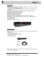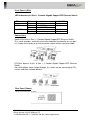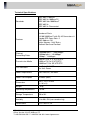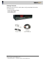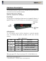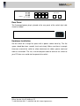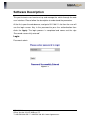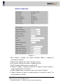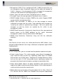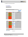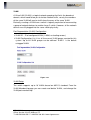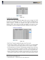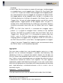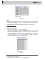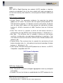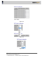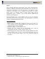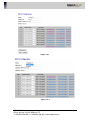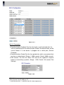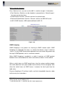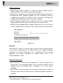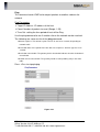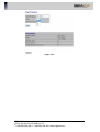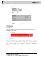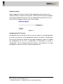
1
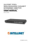
6 Port Gigabit + 2 Giga Combo
RJ45/SFP Web Smart Switch
Model: 300-7306GE2GC
I
SIGNAMAX a.s.
Office: Vlarska 22, 627 00 Brno, CZ
T:+420 533 338 854 l F:+420 533 338 883 l www.signamax.eu
FCC Warning
This device has been tested and found to comply with limits for a Class B
digital device, pursuant to Part 2 and 15 of FCC Rules. These limits are
designed to provide reasonable protection against harmful interference when
the equipment is operated in a commercial environment. This equipment
generates and radiates radio frequency energy and, if not installed and used
in accordance with the user’s manual, it may cause interference in which
case users will be required to correct interference at their own expenses.
CE Warning
This is a Class B product. In a domestic environment, this product may
cause radio interference in which case the user may be required to take
adequate measures.
Introduction
The Switch provides 6 10/100/1000Mbps NWAY RJ-45 ports and can support
2 Combo Gigabit Copper/SFP to uplink. It was designed for easy
installation and high performance in an environment where traffic on the
network and the number of user increase continuously. With newest Gigabit
chip set, Gigabit Ethernet switch can fully support highest speed without
hanging on problem even when Full-Duplex full loaded.
The switch also provides automatic crossover detection functionality on each
port. It is simple and friendly to up-link to another switch without crossover
cable.
This is specifically designed for medium to large workgroups. The Switch can
be installed where space is limited; moreover it provides smooth network
migration and easy upgrade to network capacity.
II
SIGNAMAX a.s.
Office: Vlarska 22, 627 00 Brno, CZ
T:+420 533 338 854 l F:+420 533 338 883 l www.signamax.eu
Key Features
Complies with the IEEE802.3 Ethernet, IEEE802.3u Fast Ethernet and IEEE
802.3ab/z Gigabit Ethernet Standards
Provides 6 10/100/1000Mbps Gigabit switching ports and 2 Combo Gigabit
Copper/SFP
Non-blocking & Non-head-of-line blocking full wire speed forwarding
Store-and-forward operation support
Embedded 144K Bytes packet buffer
Provides 8K MAC address entry
Supports broadcast storm filtering
All ports provide Auto-Negotiation and Auto -MDI/ MDI-X functions
Supports flow control: back pressure for Half-duplex and IEEE 802.3x for
Full-duplex mode
Smart plug & play
Optional: 19” rack-mount Kits
Package Contents
Before you start to install this Switch, please verify your package contain the
following items:
• One Rack-mount Switch
• Rack-mount Kit for Rack Installation
• One AC Power Cord
• One User’s Manual
Note: If any of these items is found missing or damaged, please contact your
local supplier for replacement.
III
SIGNAMAX a.s.
Office: Vlarska 22, 627 00 Brno, CZ
T:+420 533 338 854 l F:+420 533 338 883 l www.signamax.eu
Front Panel (LEDs)
LED Indicators of 6 Port + 2 Combo Gigabit Copper/SFP Ethernet Switch
LED
Power
1000M
Link/ ACT
Status
On
On
off
On
Flashing
Description
Power on
Link 1000Mbps
Link 10/100Mbps
Link
Data activating
No. Of LED
Power
8 (1~8)
8 (1~8)
8 (1~8)
Connections
Switch/Hub to this 6 Port + 2 Combo Gigabit Copper/SFP Ethernet Switch
This switch provides automatic crossover detection functionality for any port.
It is simple and friendly to up-link to another switch without crossover cable.
PC/Other devices to this 6 Port + 2 Combo Gigabit Copper/SFP Ethernet
Switch
Via a twisted pair cable straight through, this switch can be connected to PCs,
servers and other network devices.
Rear Panel (Power)
AC input (100~240V/AC, 50~60Hz)
‘
IV
SIGNAMAX a.s.
Office: Vlarska 22, 627 00 Brno, CZ
T:+420 533 338 854 l F:+420 533 338 883 l www.signamax.eu
Technical Specifications
Standards
IEEE 802.3 10BaseT
IEEE 802.3u 100BaseTX
IEEE 802.3ab 1000BaseT
IEEE 802.3z
IEEE 802.3x Flow control
Features
Number of Ports:
10/100/1000BaseT with RJ-45 Connectors: 8
Combo SFP Open Slots: 2
MAC Address: 8K
Buffer Memory: 144K Bytes
Method: Store and Forward
Filtering/
Forwarding Rates
1000Mbps port – 1,488,000pps
100Mbps port – 148,800pps
10Mbps – 14,880pps
Transmission Media
10BaseT Cat. 3, 4, 5 UTP/STP
100BaseTX Cat. 5 UTP/STP
1000BaseT Cat. 5E UTP/STP
LED Indicators
Per Port: LINK/ACT
Per Unit: Power
Power Requirement
100~240V/AC, 50~60Hz
Power Consumption
20 Watts (Max)
Dimensions
288 × 124 × 44 mm
(L x W x H)
Weight
1.5 kg
Operating Temperature
0 to 40
Storage Temperature
-20 to 90
Humidity
10 to 90% RH (non-condensing)
Certifications
FCC Class A, CE
V
SIGNAMAX a.s.
Office: Vlarska 22, 627 00 Brno, CZ
T:+420 533 338 854 l F:+420 533 338 883 l www.signamax.eu
Content
Content………………………………………………………………………………….I
Introduction…………………………………………………………………………..1
Product Overview……………………………………………………………………………….1
Web Management Feature…………………………………………………………………….1
Specification……………………………………………………………………………………..2
Mechanical……………………………………………………………………………………....2
Performance…………………………………………………………………………………........2
Package Contents……………………………………………………………………………...3
Hardware Description ……………………………………………………………….4
Physical Dimensions / Weight………………………………………………………………...4
Front Panel……………………………………………………………………………………...4
LED Indicators…………………………………………………………………………………..5
Rear Panel………………………………………………………………………………………5
Hardware Installation…………………………………………………………………………..5
Software Description………………………………………………………………..6
Login……………………………………………………………………………………………..6
Configuration……………………………………………………………………………………7
System ..…………………………………………………………………….…………….....7
System Configuration……………………………………………...…………………...7
Ports ………….…………………………………………………..…………………………..9
Port
Configuration
……………………...……………….…………………………..9
Vlan…………………………………….……………………….…………………………...10
Port Segmentation (VLAN) Configuration……………….……………………..........11
Add a Vlan………………………………………………….……………...……………11
VLAN Configuration List………………………………….………………..………….11
VLAN Setup……………………………………………….…...……………………….11
VLAN Per Port Configuration…………………………...……………………………12
Aggregation…………………………………………………………………………….….12
Aggregation / Trunking Configuration…………………………………………….....12
LACP……………………………………………………………………………….……….14
LACP Port Configuration……………………………………...………………………14
RSTP………………………………………………………………………………………..15
RSTP System Configuration……………….………………………………………...15
RSTP Port Configuration………….………………………………………………….17
VI
SIGNAMAX a.s.
Office: Vlarska 22, 627 00 Brno, CZ
T:+420 533 338 854 l F:+420 533 338 883 l www.signamax.eu
802.1X………………………………………………………………………………………...18
802.1X Configuration………………………………………………………………..19
802.1X Parameters………………………………………………………………….20
802.1X Statistics for Port 1………………………………………………………….21
IGMP Snopping………………………………………………………………………….21
IGMP Configuration…………………………………………………………………22
Mirrioring…………………………………………………………………………………22
Moirrioring Configuration…………………………………………………………...22
QoS……………………………………………………………………………………….24
QoS Configuration…………………………………………………………………..24
QoS Mode: QoS Disabled………………………………………………………….24
QoS Mode: 802.1p…………………………………………………………………..25
QoS Mode: DSCP…………………………………………………………………...26
Storm Control……………………………………………………………………………27
Storm Control Configuration……………………………………………………….28
Monitoring …………………………………………………………………………………...28
Statistic Overview……………………………………………………………………… 26
Detailed Statistic………………………………………………………………………..29
LACP Status……………………………………………………………………………. 30
LACP Aggregation Overview……………………………………………………....30
LACP Port Status……………………………………………………………………30
RSTP Status……………………………………………………………………………..31
RSTP VLAN Bridge Overview……………………………………………………..31
RSTP Port Status…………………………………………………………………....32
IGMP Status……………………………………………………………………………..32
IGMP Status………………………………………………………………………….32
VeriPHY…………………………………………………………………………………..33
VeriPHY Cable Diagnostics................................................................................33
Ping……………………………………………………………………………………....35
Ping Parameters………………………………………………………………….....35
Maintenance………………………………………………………………………………...37
Warm Restart…………………………………………………………………………....37
Factory Default………………………………………………………………………….37
Software Upload………………………………………………………………………..38
Configuration File Transfer…………………………………………………………....38
Logout……………………………………………………………………………………39
VII
SIGNAMAX a.s.
Office: Vlarska 22, 627 00 Brno, CZ
T:+420 533 338 854 l F:+420 533 338 883 l www.signamax.eu
Introduction
Product Overview
This
switch
is
a
Web
Smart
Switch
equipped
with
8-ports
10/100/1000BaseT(X) plus 2-port gigabit SFP open slots. It was designed for
easy installation and high performance in an environment where traffic is on
the network and the number of users increases continuously. The compact
rigid desktop size was specifically designed for small to medium workgroups.
It can be installed where space is limited; moreover, it provides smooth
network migration and easy upgrade to network capacity.
In addition, the switch features comprehensive and useful function such as
QoS (Quality of Service), Spanning Tree, VLAN, Port Trunking, Bandwidth
Control, Port Security, SNMP/RMON, IGMP Snooping capability via the
intelligent software. It is suitable for both metro-LAN and office application.
Web Management Features
Port Management
Port Configuration
Port Mirroring
Bandwidth Control
Broadcast Strom Control
VLAN Setting
Port-based/ Tag-based
Trunking
2 groups per device, 4 ports per group
QoS Setting
Security Setting
MAC address filtering
TCP/UDP Port filtering
IGMP Snooping
Backup/Recovery Configuration
1
SIGNAMAX a.s.
Office: Vlarska 22, 627 00 Brno, CZ
T:+420 533 338 854 l F:+420 533 338 883 l www.signamax.eu
Specifications
Standard
IEEE 802.3 10BaseT
IEEE 802.3u 100BaseTX
IEEE 802.ab 1000BaseT
IEEE 802.3z 1000BaseSX/LX
IEEE 802.3x Flow Control
IEEE 802.1x Port-based Network Access Control
IEEE 802.1Q VLAN Tagging
IEEE 802.3ad Port aggregation
IEEE 802.1d Spanning tree protocol
IEEE 802.1w Rapid Spanning tree protocol
IEEE 802.1p Class of service, Priority Protocols
Number of Port
8-port 10/100/100BaseT(X)+2 Gigabit SFP Open Slots
Mechanical
LED Indicator
Per Port: Link/ Act, 1000M
Per Unit: Power
Power Consumption: 10 Watts (Max)
Power Input: 100~240V/AC, 50~60HZ
Product Dimensions/ Weight
228 × 124 × 44 mm (L × W ×H) / 0.95kg
Performance
MAC Address: 8K
Buffer Memory: 144K Bytes
Jumbo Frames: 9.6K
Transmission Method: Store and Forward
2
SIGNAMAX a.s.
Office: Vlarska 22, 627 00 Brno, CZ
T:+420 533 338 854 l F:+420 533 338 883 l www.signamax.eu
Package Contents
Before you start to install this switch, please verify your package that contains
the following items:
One Fast Ethernet Switch
One Power Cord
User Manual CD
3
SIGNAMAX a.s.
Office: Vlarska 22, 627 00 Brno, CZ
T:+420 533 338 854 l F:+420 533 338 883 l www.signamax.eu
Hardware Description
This part primarily presents hardware of the EW-4082VW, physical dimensions
and functional overview would be described.
Physical Dimensions/ Weight
228 × 124 × 44 mm (L × W × H) / 0.95KG
Front Panel
The front Panel of the Web Smart Switch consists of 8 gigabit RJ-45 ports+2
gigabit SFP open slot. The LED Indicators are also located on the front panel.
RJ-45 Port
LED
Display
SFP Open
Slot
LED Indicators
The LED Indicators present real-time information of systematic operation
status. The following table provides description of LED status and their
meaning.
Table 1-1 LED Indicators
LED
Power LED
SFP
Status LED
Each Port upper
LED
Each Port lower
LED
Status
Description
On
Power is on.
Off
Power is off.
On
SFP Module is connected
Off
SFP Module is disconnected
On
Giga Link is connected
On
10/100/1000 Link is connected
※
Each port upper LED is Giga Link and lower LED is 10/100/1000 Act/ Link
4
SIGNAMAX a.s.
Office: Vlarska 22, 627 00 Brno, CZ
T:+420 533 338 854 l F:+420 533 338 883 l www.signamax.eu
SFP Status
Power
Rear Panel
The 3-pronged power plug is placed at the rear panel of the switch right side
shown as below.
Hardware Installation
Set the switch on a large flat space with a power socket close by. The flat
space should be clean, smooth, level and sturdy. Make sure there is enough
clearance around the switch to allow attachment of cables, power cord and
allow air circulation. The last, use twisted pair cable to connect this switch to
your PC then user could start to operate the switch.
5
SIGNAMAX a.s.
Office: Vlarska 22, 627 00 Brno, CZ
T:+420 533 338 854 l F:+420 533 338 883 l www.signamax.eu
Software Description
This part instructs user how to set up and manage the switch through the web
user interface. Please follow the description to understand the procedure.
At the first, open the web browser, and go to 192.168.2.1 site then the user will
see the login screen. Key in the password to pass the authentication then
clicks the Apply. The login process is completed and comes out the sign
“Password successfully entered”.
Login
Password: admin
Figure 1-1
6
SIGNAMAX a.s.
Office: Vlarska 22, 627 00 Brno, CZ
T:+420 533 338 854 l F:+420 533 338 883 l www.signamax.eu
After the user login, the right side of website shows all functions as Fig. 1-2.
Figure 1-2
Configuration
System
System Configuration
This page shows system configuration information. User can configure lots of
information as below:
7
SIGNAMAX a.s.
Office: Vlarska 22, 627 00 Brno, CZ
T:+420 533 338 854 l F:+420 533 338 883 l www.signamax.eu
Figure 1-3
MAC Address: Displays the unique hardware address assigned by
manufacturer (default).
S/W Version: Displays the switch’s firmware version.
H/W Version: Displays the switch’s Hardware version.
DHCP Enabled: Click the box to enable DHCP
Fallback IP address: Manually assign the IP address that the network is
using. The default IP is 192.168.2.1
Fallback Subnet Mask: Assign the subnet mask to the IP address
Fallback Gateway: Assign the network gateway for industrial switch. The
default gateway is 0.0.0.0.
8
SIGNAMAX a.s.
Office: Vlarska 22, 627 00 Brno, CZ
T:+420 533 338 854 l F:+420 533 338 883 l www.signamax.eu
Management VLAN: ID of a configured VLAN (1-4094) through which you
can manage the switch. By default, all ports on the switch are members of
VLAN 1. However, if the management VLAN is changed, the management
station must be attached to a port belonging to this VLAN.
Name: Type in the new user name (The default value is ‘admin’).
Password: Type in the new password (The default value is ‘admin’).
SNMP Enabled: Enables or disables SNMP on the switch. Supports SNMP
version 1and 2c management clients.
SNMP Trap Destination: IP address of the trap manager to receive
notification messages from this switch. Traps indicating status changes are
issued by the switch to specified trap managers. You must specify trap
managers so that key events are reported by this switch to your
management station.
SNMP Read Community: A community string that acts like a password and
permits access to the SNMP database on this switch. Authorized
management stations are only able to retrieve MIB objects.
SNMP Trap Community: Community string sent with the notification
operation.
Ports
Port Security ensures access to a switch port based on MAC address, limits
the total number of devices from using a switch port, and protects against MAC
flooding attacks.
Port Configuration
In Port Configuration, you can set and view the operation mode for each port.
Enable Jumbo Frames: This switch provides more efficient throughput for
large sequential data transfers by supporting jumbo frames on Gigabit
Ethernet ports up to 9216 bytes. Compared to standard Ethernet frames
that run only up to 1.5 KB, using jumbo frames significantly reduces the
per-packet overhead required to process protocol encapsulation fields.
Power Saving Mode: Adjusts the power provided to ports based on the
length of the cable used to connect to other devices. Only sufficient power is
used to maintain connection requirements.
Mode: allow user to manually set the port speed such as Auto, 10 half, 10
Full, 100 Half, 100 Full, 1000 Full or Disabled. User may press Apply button
9
SIGNAMAX a.s.
Office: Vlarska 22, 627 00 Brno, CZ
T:+420 533 338 854 l F:+420 533 338 883 l www.signamax.eu
to complete the configuration procedure.
Figure 1-4-1
Figure 1-4-2
10
SIGNAMAX a.s.
Office: Vlarska 22, 627 00 Brno, CZ
T:+420 533 338 854 l F:+420 533 338 883 l www.signamax.eu
VLAN
A Virtual LAN (VLAN) is a logical network grouping that limits the broadcast
domain, which would allow you to isolate network traffic, so only the members
of the same VLAN will receive traffic from the ones of the same VLAN.
Basically, creating a VLAN from a switch is logically equivalent of reconnecting
a group of network devices to another Layer 2 switch. However, all the network
devices are still plugged into the same switch physically.
Port Segmentation (VLAN) Configuration
VLAN ID: ID of configured VLAN (1-4094, no leading zeroes).
VLAN Configuration List: Lists all the current VLAN groups created for this
system. Up to 64 VLAN groups can be defined. VLAN 1 is the default
untagged VLAN.
Figure 1-5-1
VLAN Setup
The switch supports up to 16 VLANs based on 802.1Q standard. From the
VLAN Membership page you can create and delete VLANs, and change the
VLAN port membership.
11
SIGNAMAX a.s.
Office: Vlarska 22, 627 00 Brno, CZ
T:+420 533 338 854 l F:+420 533 338 883 l www.signamax.eu
Figure 1-5-2
VLAN Per Port Configuration
The 802.1Q Per Port Configuration page allows you to change the VLAN
parameters for individual ports or trunks. You can configure VLAN behavior for
specific interfaces, including the accepted frame types and default VLAN
identifier (PVID). Each row of the table corresponds to one port or trunk;
trunked ports cannot be configured individually; configure the trunk instead.
Figure 1-5-3
Port/Trunk: The port number of the port or the ID of a trunk.
VLAN Aware Enabled: VLAN aware ports are able to use VLAN tagged
frames to determine the destination VLAN of a frame. (Default: Enabled)
VLAN aware ports will strip the VLAN tag from received frames and insert
the tag in transmitted frames (except for the PVID). VLAN unaware ports will
not strip the tag from received frames or insert the tag in transmitted frames.
Ingress Filtering Enabled: If enabled, incoming frames for VLANs which do
not include this ingress port in their member set will be discarded. (Default:
12
SIGNAMAX a.s.
Office: Vlarska 22, 627 00 Brno, CZ
T:+420 533 338 854 l F:+420 533 338 883 l www.signamax.eu
Disabled)
Packet Type: Sets the interface to accept all frame types, including tagged
or untagged frames, or only tagged frames. (Default: All) If the Packet Type
is set to “All,” the port can accept incoming tagged and untagged packets.
Any received packets that are untagged are assigned to the default VLAN.
Any tagged packets will be dropped unless the port is a member of the
VLAN identified by the VLAN tag in the packet. If the Packet Type is set to
“Tagged Only,” the port will drop untagged packets and will only receive
tagged packets. Tagged packets will be dropped unless the port is a
member of the VLAN identified by the VLAN tag in the packet. Switches
should be connected to each other with the Packet Type set to “Tagged
Only.”
PVID: The PVID (Port VLAN ID) is associated with untagged, ingress
packets. It is assigned to untagged frames received on the specified
interface. The PVID has no effect on ports that have Packet Type set to
“Tagged Only.” (Default PVID: 1) It is not possible to remove a port from
VLAN 1 unless its PVID has been changed to something other than 1.
Outgoing packets are tagged unless the packet’s VLAN ID is the same as
the PVID. When the PVID is set to “None,” all outgoing packets are tagged.
※Note: If you select “Tagged Only” mode for a port, we recommend setting
the PVID to “None” as the standard configuration.
Aggregation
Port trunk allows multiple links to be bundled together and act as a single
physical link for increased throughput. It provides load balancing, and
redundancy of links in a switched inter-network. Actually, the link does not
have an inherent total bandwidth equal to the sum of its component physical
links. Traffic in a trunk is distributed across an individual link within the trunk in
a deterministic method that called a hash algorithm. The hash algorithm
automatically applies load balancing to the ports in the trunk. A port failure
within the trunk group causes the network traffic to be directed to the remaining
ports. Load balancing is maintained whenever a link in a trunk is lost or
returned to service.
Aggregation / Trunking Configuration
To assign a port to a trunk, click the required trunk number, then click Apply.
13
SIGNAMAX a.s.
Office: Vlarska 22, 627 00 Brno, CZ
T:+420 533 338 854 l F:+420 533 338 883 l www.signamax.eu
Figure 1-6
LACP
IEEE 802.3ad Link Aggregation Control Protocol (LACP) increases bandwidth
by automatically aggregating several physical links together as a logical trunk
and providing load balancing and fault tolerance for uplink connections.
LACP Port Configuration
Port: The port number.
Enabled: Enables LACP on the associated port.
Key Value: Configures a port's LACP administration key. The port
administrative key must be set to the same value for ports that belong to the
same link aggregation group (LAG). If this administrative key is not set when
an LAG is formed (i.e., it has the null value of 0), this key will automatically
be set to the same value as that used by the LAG.
Figure 1-7
14
SIGNAMAX a.s.
Office: Vlarska 22, 627 00 Brno, CZ
T:+420 533 338 854 l F:+420 533 338 883 l www.signamax.eu
RSTP
IEEE 802.1w Rapid Spanning tree protocol (LACP) provides a loop-free
network and redundant links to the core network with rapid convergence to
ensure faster recovery from failed links, enhancing overall network stability and
reliability.
RSTP System Configuration
System Priority: This parameter configures the spanning tree priority
globally for this switch. The device with the highest priority becomes the
STP root device. However, if all devices have the same priority, the device
with the lowest MAC address will then become the root device. Number
between 0 - 61440 in increments of 4096. Therefore, there are 16 distinct
values.
Hello Time: Interval (in seconds) at which the root device transmits a
configuration message (BPDU frame). Number between 1-10 (default is 2).
Max Age – The maximum time (in seconds) a device can wait without
receiving a configuration message before attempting to reconfigure. That
also means the maximum life time for a BPDU frame. Number between 6-40
(default is 20).
Forward Delay: The maximum time (in seconds) the root device will wait
before changing states (i.e., discarding to learning to forwarding). Number
between 4 – 30 (default is 15).
Force Version: Set and show the RSTP protocol to use. Normal - use RSTP,
Compatible - compatible with STP.
Figure 1-8-1
RSTP Port Configuration
Port: The port ID. It cannot be changed. Aggregations mean any configured
trunk group.
Enabled: Click on the tick-box to enable/disable the RSTP protocol for the
15
SIGNAMAX a.s.
Office: Vlarska 22, 627 00 Brno, CZ
T:+420 533 338 854 l F:+420 533 338 883 l www.signamax.eu
port.
Edge: Expect the port to be an edge port (linking to an end station) or a link
to another STP device.
Path Cost: This parameter is used by the STP to determine the best path
between devices. Therefore, lower values should be assigned to ports
attached to faster media, and higher values assigned to ports with slower
media. Set the RSTP pathcost on the port. Number between 0 - 200000000.
0 means auto generated pathcost.
16
SIGNAMAX a.s.
Office: Vlarska 22, 627 00 Brno, CZ
T:+420 533 338 854 l F:+420 533 338 883 l www.signamax.eu
Figure 1-8-2
Figure 1-8-3
Figure 1-8-4
17
SIGNAMAX a.s.
Office: Vlarska 22, 627 00 Brno, CZ
T:+420 533 338 854 l F:+420 533 338 883 l www.signamax.eu
802.1X
802.1X provides port-based authentication, which involves communications
between a supplicant, authenticator, and authentication server. Port refers to a
single point of attachment to the LAN infrastructure. The supplicant is often
software on a client device, such as a laptop; the authenticator us a network
device, such as an Ethernet switch or wireless access point; and the
authentication server is typically a host running software supporting the
RADIUS and EAP protocols.
Port-based Network access control (PNAC) ensures all users are authorized
before being granted access to the network. User authentication is carried out
using any standard-based RADIUS server.
802.1X Configuration
Mode: Enables or disables 802.1X globally for all ports on the switch. The
802.1X protocol must be enabled globally for the switch before the port
settings are active. (Default: Disabled)
RADIUS IP: Address of authentication server.
RADIUS UDP Port: Network port of authentication server used for
authentication messages. (Range: 1-65535; Default: 1812)
RADIUS Secret: Sets the text string used for encryption between the switch
and the RADIUS server. This key is used to authenticate logon access for
the client. Do not use blank spaces in the string. (Maximum length: 48
characters).
18
SIGNAMAX a.s.
Office: Vlarska 22, 627 00 Brno, CZ
T:+420 533 338 854 l F:+420 533 338 883 l www.signamax.eu
Figure 1-9-1
Figure 1-9-2
19
SIGNAMAX a.s.
Office: Vlarska 22, 627 00 Brno, CZ
T:+420 533 338 854 l F:+420 533 338 883 l www.signamax.eu
Figure 1-9-3
802.1X Parameters
Reauthentication Enabled: Sets the client to be re-authenticated after the
interval specified by the Re-authentication Period. Re-authentication can be
used to detect if a new device is plugged into a switch port. (Default:
Disabled)
Reauthentication Period: Sets the time period after which a connected client
must be re-authenticated. (Range: 1-3600 seconds; Default: 3600 seconds)
EAP timeout: The time the switch shall wait for the supplicant response
before re-transmitting a packet. (Range: 1-255; Default: 30 seconds Port
Settings)
Figure 1-9-4
20
SIGNAMAX a.s.
Office: Vlarska 22, 627 00 Brno, CZ
T:+420 533 338 854 l F:+420 533 338 883 l www.signamax.eu
802.1x statistics for port 1
Press Statistics link, user can see the 802.1x statistics for port 1 information.
Port Statistics: Statistics can be viewed on a per-port basis. Select the port
that you want to view here.
Authenticator Counters: General statistics for authenticator.
Backend Authenticator Counters: General statistics for RADIUS server.
802.1X MIB Counters: MIB module defined for 802.1X.
Figure 1-9-5
IGMP Snooping
IGMP Snooping is the process of listening to IGMP network traffic. IGMP
Snooping, as implied by the name, is a feature that allows a layer 2 switch to
“listen in” on the IGMP conversation between hosts and routers by processing
the layer3 IGMP packets sent in a multicast network.
When IGMP Snooping is enabled in a switch it analyzes all IGMP packets
between hosts connected to the switch and multicast routers in the network.
When a switch hears an IGMP report from a host for a given multicast group,
the switch adds the host’s port number to the multicast list for that group. And,
when the switch hears an IGMP Leave, it removes the host’s port from the
table entry.
Prevents flooding of IP multicast traffic, and limits bandwidth intensive video
traffic to only the subscribers.
21
SIGNAMAX a.s.
Office: Vlarska 22, 627 00 Brno, CZ
T:+420 533 338 854 l F:+420 533 338 883 l www.signamax.eu
IGMP Configuration
IGMP Enabled: When enabled, the switch will monitor network traffic to
determine which hosts want to receive multicast traffic.
Router Ports: Set if ports are connecting to the IGMP administrative routers.
Unregistered IPMC Flooding enabled: Set the forwarding mode for
unregistered (not-joined) IP multicast traffic. The traffic will flood when
enabled, and forward to router-ports only when disabled.
IGMP Snooping Enabled: When enabled, the port will monitor network
traffic to determine which hosts want to receive the multicast traffic.
IGMP Querying Enabled: When enabled, the port can serve as the Querier,
which is responsible for asking hosts if they want to receive multicast traffic.
Figure 1-10-1
Mirroring
Port Mirroring is used on a network switch to send a copy of network packets
seen on one switch port (or an entire VLAN) to a network monitoring
connection on another switch port. This is commonly used for network
appliances that require monitoring of network traffic, such as an
intrusion-detection system.
Mirroring Configuration
Port to Mirror to: The port that will “duplicate” or “mirror” the traffic on the
source port. Only incoming packets can be mirrored. Packets will be
dropped when the available egress bandwidth is less than ingress
bandwidth.
Ports to Mirror: Select the ports that you want to mirror from this section of
the page. A port will be mirrored when the “Mirroring Enabled” check-box is
checked.
22
SIGNAMAX a.s.
Office: Vlarska 22, 627 00 Brno, CZ
T:+420 533 338 854 l F:+420 533 338 883 l www.signamax.eu
Figure 1-11-1
23
SIGNAMAX a.s.
Office: Vlarska 22, 627 00 Brno, CZ
T:+420 533 338 854 l F:+420 533 338 883 l www.signamax.eu
Figure 1-11-2
QoS
In QoS Mode, select QoS Disabled, 802.1p, or DSCP to configure the related
parameters.
QoS Configuration
Strict: Services the egress queues in sequential order, transmitting all traffic
in the higher priority queues before servicing lower priority queues.
WRR: Weighted Round-Robin shares bandwidth at the egress ports by
using scheduling weights with default values of 1, 2, 4, 8 for queues 0
through 7, respectively. (This is the default selection.)
※Note: WRR can only be selected if Jumbo Frame mode is disabled on the
Port Configuration page
24
SIGNAMAX a.s.
Office: Vlarska 22, 627 00 Brno, CZ
T:+420 533 338 854 l F:+420 533 338 883 l www.signamax.eu
Figure 1-12-1
QoS Mode: QoS Disabled
When the QoS Mode is set to QoS Disabled, the following table is displayed.
Figure 1-12-2
QoS Mode: 802.1p
Packets are prioritized using the 802.1p field in the VLAN tag. This field is
three bits long, representing the values 0 - 7. When the QoS Mode is set to
802.1p, the 802.1p Configuration table appears, allowing you to map each of
the eight 802.1p values to a local priority queue (low, normal, medium or high).
The default settings are shown below.
When the QoS Mode is set to 802.1p, the 802.1p Configuration table is
displayed as shown below.
25
SIGNAMAX a.s.
Office: Vlarska 22, 627 00 Brno, CZ
T:+420 533 338 854 l F:+420 533 338 883 l www.signamax.eu
Figure 1-12-3
Figure 1-12-4
QoS Mode: DSCP
DSCP: Packets are prioritized using the DSCP (Differentiated Services Code
Point) value. The Differentiated Services Code Point (DSCP) is a six-bit field
that is contained within an IP (TCP or UDP) header. The six bits allow the
DSCP field to take any value in the range 0 - 63. When QoS Mode is set to
DSCP, the DSCP Configuration table is displayed, allowing you to map each of
26
SIGNAMAX a.s.
Office: Vlarska 22, 627 00 Brno, CZ
T:+420 533 338 854 l F:+420 533 338 883 l www.signamax.eu
the DSCP values to a hardware output queue (low, normal, medium or high).
The default settings map all DSCP values to the high priority egress queue.
User can use the Prioritize Traffic drop-down list to quickly set the values in the
DSCP Configuration table to a common priority queue. Use Custom if you want
to set each value individually.
When the QoS Mode is set to DSCP, the DSCP Configuration table is
displayed as shown below.
Figure 1-12-5
Figure 1-12-6
Storm Control
Broadcast storms may occur when a device on your network is malfunctioning,
or if application programs are not well designed or properly configured. If there
is too much broadcast traffic on your network, performance can be severely
degraded or everything can come to complete halt.
You can protect your network from broadcast storms by setting a threshold for
broadcast traffic for each port. Any broadcast packets exceeding the specified
27
SIGNAMAX a.s.
Office: Vlarska 22, 627 00 Brno, CZ
T:+420 533 338 854 l F:+420 533 338 883 l www.signamax.eu
threshold will then be dropped.
Storm Control Configuration
There are three type of traffic which can be rate limited, including broadcast
multicast frame and Flooded Uncast Rate.
Figure 1-13-1
Enable Rate Limit: Click the check box to enable storm control.
Rate (number of frames per second): The Rate field is set by a single
drop-down list. The same threshold is applied to every port on the switch.
When the threshold is exceeded, packets are dropped, irrespective of the
flow-control settings.
Web: Click PORTS, Storm Control. This page enables you to set the
broadcast storm control parameters for every port on the switch.
Figure 1-13-2
Monitoring
Statistic Overview
Statistic Overview for all ports
28
SIGNAMAX a.s.
Office: Vlarska 22, 627 00 Brno, CZ
T:+420 533 338 854 l F:+420 533 338 883 l www.signamax.eu
User can mirror traffic from any source port to a target port for real-time
analysis the following figures shows clearly the statistics overview.
Figure 2-1
Detailed Statics
Figure 2-2
LACP Status
LACP Aggregation Overview
29
SIGNAMAX a.s.
Office: Vlarska 22, 627 00 Brno, CZ
T:+420 533 338 854 l F:+420 533 338 883 l www.signamax.eu
Figure 2-3-1
Port: The port number.
Port Active: Shows if the port is a member of an active LACP group.
Partner Port Number: A list of the ports attached at the remote end of this
LAG link member.
Operational Port Key: Current operational value of the key used by this
LAG.
LACP Port Status
Figure 2-3-2
30
SIGNAMAX a.s.
Office: Vlarska 22, 627 00 Brno, CZ
T:+420 533 338 854 l F:+420 533 338 883 l www.signamax.eu
RSTP Status
RSTP VLAN Bridge Overview
Figure 2-4-1
Hello Time: Interval (in seconds) at which the root device transmits a
configuration message.
Max Age: The maximum time (in seconds) a device can wait without
receiving a configuration message before attempting to reconfigure. All
device ports (except for designated ports) should receive configuration
messages at regular intervals. Any port that age out STA information
(provided in the last configuration message) becomes the designated port
for the attached LAN. If it is a root port, a new root port is selected from
among the device ports attached to the network.
Fwd Delay: The maximum time (in seconds) the root device will wait before
changing states (i.e., discarding to learning to forwarding). This delay is
required because every device must receive information about topology
changes before it starts to forward frames. In addition, each port needs time
to listen for conflicting information that would make it return to a discarding
state; otherwise, temporary data loops might result.
Topology: Indicates if spanning tree topology is steady or undergoing
reconfiguration. (The time required for reconfiguration is extremely short, so
no values other that “steady” state are likely to be seen in this field.)
Root ID : The priority and MAC address of the device in the Spanning Tree that
this switch has accepted as the root device, and the port connected to the
root device.
31
SIGNAMAX a.s.
Office: Vlarska 22, 627 00 Brno, CZ
T:+420 533 338 854 l F:+420 533 338 883 l www.signamax.eu
RSTP Port Status
Figure 2-4-2
Port/Group: The number of a port or the ID of a static trunk.
Path Cost: The cost for a packet to travel from this port to the root in the
current Spanning Tree configuration. The slower the media, the higher the
cost.
Edge Port: Shows if this port is functioning as an edge port, either through
manual selection (see the RSTP Port Configuration table) or auto-detection.
Note that if the switch detects another bridge connected to this port, the
manual setting for Edge Port will be overridden, and the port will instead
function as a point-to-point connection.
P2P Port: Shows if this port is functioning as a Point-to-Point connection to
exactly one other bridge. The switch can automatically determine if the
interface is attached to a point-to-point link or to shared media. If shared
media is detected, the switch will assume that it is connected to two or more
bridges.
Protocol: Shows the spanning tree protocol functioning on this port, either
RSTP or STP (that is, STP-compatible mode).
IGMP Status
IGMP Status
IGMP Status shows the IGMP Snooping statistics for the whole switch.
VLAN ID: VLAN ID number.
Querier: Show whether Querying is enabled.
Queries transmitted: Show the number of transmitted Query packets.
32
SIGNAMAX a.s.
Office: Vlarska 22, 627 00 Brno, CZ
T:+420 533 338 854 l F:+420 533 338 883 l www.signamax.eu
Queries received: Show the number of received Query packets.
v1 Reports: Show the number of received v1 Report packets.
v2 Reports: Show the number of received v2 Report packets.
v3 Reports: Show the number of received v2 Report packets.
v3 Leave: Show the number of v3 leave packets received.
Figure 2-5
VeriPHY
VeriPHY Cable Diagnostics
User can perform cable diagnostics for all ports or selected ports to diagnose
any cable faults (short, open etc..) and feedback a distance to the fault.
Cable Diagnostics: Cable diagnostics is performed on a per-port basis.
Select the port number from the drop-down list.
Cable Status: Shows the cable length, operating conditions and isolates a
variety of common faults that can occur on Category 5 twisted pair cabling.
Figure 2-6-1
33
SIGNAMAX a.s.
Office: Vlarska 22, 627 00 Brno, CZ
T:+420 533 338 854 l F:+420 533 338 883 l www.signamax.eu
Figure 2-6-2
Figure 2-6-3
Figure 2-6-4
34
SIGNAMAX a.s.
Office: Vlarska 22, 627 00 Brno, CZ
T:+420 533 338 854 l F:+420 533 338 883 l www.signamax.eu
Ping
This command sends ICMP echo request packets to another node on the
network.
Ping Parameters
Target IP Address: IP address of the host
Count: Number of packets to send. (Range: 1-20)
Time Out: setting the time period of host will be Ping
Use the ping command to see if another site on the network can be reached.
The following are some results of the ping command:
Normal response: The normal response occurs in one to ten seconds, depending on
network traffic.
Destination does not respond: If the host does not respond, a “timeout” appears in ten
seconds.
Destination unreachable: The gateway for this destination indicates that the destination is
unreachable.
Network or host unreachable: The gateway found no corresponding entry in the route
table.
Press <Esc> to stop pinging.
Figure 2-7-1
35
SIGNAMAX a.s.
Office: Vlarska 22, 627 00 Brno, CZ
T:+420 533 338 854 l F:+420 533 338 883 l www.signamax.eu
Figure 2-7-2
36
SIGNAMAX a.s.
Office: Vlarska 22, 627 00 Brno, CZ
T:+420 533 338 854 l F:+420 533 338 883 l www.signamax.eu
Figure 2-7-3
Maintenance
Warm Restart
Press Yes button to restart the switch, the reset will be complete when the
power lights stop blinking.
Figure3-1
Factory Default
Forces the switch to restore the original factory settings. To reset the switch,
select “Reset to Factory Defaults” from the drop-down list and click Apply. The
LAN IP Address, Subnet Mask and Gateway IP Address will be reset to their
factory
37
SIGNAMAX a.s.
Office: Vlarska 22, 627 00 Brno, CZ
T:+420 533 338 854 l F:+420 533 338 883 l www.signamax.eu
Software upload
Select “Upgrade Firmware” from the Tools drop-down list then click on the
“Browse” button to select the firmware file. Click the APPLY button to upgrade
the selected switch firmware file. User can download firmware files for user’s
switch from the Support section of your local supplier.
Figure 3-3
Configuration File Transfer
Configuration file transfer allows you to save the switch’s current configuration
or restore a previously saved configuration back to the device. Configuration
files can be saved to any location on the web management station. To upload
the configuration file to save a configuration or "Download" to restore a
configuration. Use the Browse button to choose a file location on the web
management station, or to find a saved configuration file.
38
SIGNAMAX a.s.
Office: Vlarska 22, 627 00 Brno, CZ
T:+420 533 338 854 l F:+420 533 338 883 l www.signamax.eu
Figure 3-4
Logout
The administrator has write access for all parameters governing the onboard
agent. User should therefore assign a new administrator password as soon as
possible, and store it in a safe place.
Figure 3-5
39
SIGNAMAX a.s.
Office: Vlarska 22, 627 00 Brno, CZ
T:+420 533 338 854 l F:+420 533 338 883 l www.signamax.eu