1
FX27.ed0
3-07-2008
15:52
Pagina 1
IM-UK323-01
3231365/1
UK-Issue 1
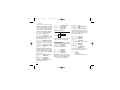
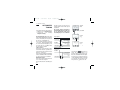
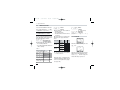
SX27 Series Process Controller
Installation and Maintenance Instructions
c
Introduction
1
2
3
274.8
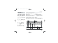
Installation
275.0
Operations
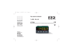
RUN
SP2 MAN
Electrical Connections
Displays
Commands
Setpoint Programmer
Technical Specifications
Printed in the UK
© Copyright 2008
FX27.ed0
3-07-2008
15:52
Pagina 2
Information
c
NOTES
ON ELECTRIC
SAFETY AND
ELECTROMAGNETIC
COMPATIBILITY.
Please, read carefully these instructions before proceeding with
the installation of the controller.
Class II instrument, real panel mounting.
This controller has been designed with compliance to:
Regulations on electrical apparatus (appliance, systems and installations) according to the European Community directive 73/23/EEC amended by the European Comunity directive 93/68/EEC and the Regulations
on the essential protection requirements in electrical apparatus EN610101 : 93 + A2:95.
Regulations on Electromagnetic Compatibility according to the
European Community directive n089/336/EEC, amended by the European
Community directive n° 92/31/EEC, 93/68/EEC, 98/13/EEC
and the following regulations:
Regulations on RF emissions
EN61000-6-3 : 2001
residential environments
EN61000-6-4 : 2001
industrial environments
Regulation on RF immunity
EN61000-6-2 : 2001
industrial equipment and system
It is important to understand that it’s responsibility of the installer to ensure
the compliance of the regulations on safety requirements and EMC.
The device has no user serviceable parts and requires special equipment
and specialised engineers. Therefore, a repair can be hardly carried on
directly by the user. For this purpose, the manufacturer provides technical assistance and the repair service for its Customers.
Please, contact your nearest Agent for further information.
All the information and warnings about safety and electromagnetic
compatibility are marked with the B sign, at the side of the note.
FX27.ed0
3-07-2008
15:52
Pagina 3
Table of contents
TABLE OF CONTENTS
1
2
3
4
5
6
7
INSTALLATION .............................................................................................................................Page
ELECTRICAL CONNECTIONS.......................................................................................Page
PRODUCT CODING ................................................................................................................Page
OPERATIONS................................................................................................................................Page
AUTOMATIC TUNING ..........................................................................................................Page
SPECIAL FUNCTIONS ........................................................................................................Page
TECHNICAL SPECIFICATIONS .....................................................................................Page
4
8
16
20
38
40
46
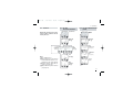
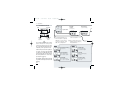
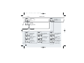
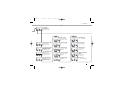
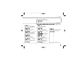
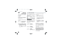
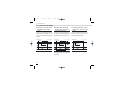
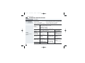
Operating mode
Resources
Control *
Alarms
Main universal input
PV
OP1
AUX
OP2
Single
1 action
Single
2 action
Double
3 action
Double
4 action
Double
5 action
Auxiliary input (option)
Digital input (option)
IL
OP3
OP4
6 Valve
OP1
OP2 OP3
OP2
OP1 OP3
OP1 OP3 OP2
OP1 OP2
OP3
OP2 OP3 OP1
OP1 OP3 OP2
(option)
Setpoint
Special functions
Fuzzy tuning with automatic selection
One shot
Auto tuning
IL connected functions
(option)
Modbus RS485
Parameterisation
Supervision
(option)
Continuous tuning
One shot
Natural Frequency
Adaptive
* Except for valve drive, each control output can be
replaced by the OP4 analogue output
3
FX27.ed0
3-07-2008
15:52
Pagina 4
1 - Installation
1
INSTALLATION
Installation must only be carried
out by qualified personnel.
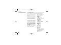
1.1 GENERAL DESCRIPTION
IP 20 Terminal block
EN61010 - 1 (IEC1010 - 1)
Before proceeding with the installation of this controller, follow the
instructions illustrated in this manual and, particularly the installation
precautions marked with the B
symbol, related to the European
Community directive on electrical
protection and electromagnetic
compatibility.
Panel surface
B
To prevent hands or metal touching parts that may be electrically
live, the controllers must be
installed in an enclosure and/or
in a cubicle.
Product code label
Mounting clamps
Sealing front panel gasket
4
Front panel
IP65 protection
EN 650529 (IEC 529)
FX27.ed0
3-07-2008
15:52
Pagina 5
1 - Installation
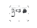
1.2 DIMENSIONAL DETAILS
1.3 PANEL CUT-OUT
48 mm
1.89 in
65 mm min
2.56 in min
45+0.6 mm
1.78+0.023 in
20 mm max
0.79 in max
65 mm min
2.56 in min
48 mm
1.89 in
45+0.6 mm
1.78+0.023 in
120 mm
4.72 in
5
FX27.ed0
3-07-2008
15:52
Pagina 6
1 - Installation
B
1.4 ENVIRONMENTAL RATINGS
Operating conditions
M
T
%Rh
Altitude up to 2000 m
Temperature 0…50°C
Relative humidity 5…95 % non-condensing
Special conditions
M
T
%Rh
P
Altitude > 2000 m
Temperature >50°C
6
Use 24Vac supply version
Use forced air ventilation
Humidity > 95 %
Warm up
Conducting atmosphere
Use filter
Forbidden Conditions
C
E
Suggestions
D
Corrosive atmosphere
Explosive atmosphere
FX27.ed0
3-07-2008
15:52
Pagina 7
1 - Installation
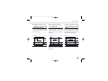
1.5 PANEL MOUNTING [1]
1.5.1 INSERT THE INSTRUMENT
1.5.2 INSTALLATION SECURING
1.5.3 CLAMPS REMOVING
1 Prepare panel cut-out
2 Check front panel gasket position
3 Insert the instrument through
the cut-out
1
1 Fit the mounting clamps
2 Push the mounting clamps
towards the panel surface to
secure the instrument
1 Insert the screwdriver in the clips
of the clamps
2 Rotate the screwdriver
1
2
1
2
3
1
2
B
1.5.4 INSTRUMENT UNPLUGGING
1 Push and
2 pull to remove the instrument
UL note
[1] For Use on a Flat Surface
of a Type 2 and Type 3
‘raintight’ Enclosure.
Electrostatic discharges can damage the instrument
Before removing the instrument the
operator must
discharge himself
1MΩ
to ground
1
2
1
7
FX27.ed0
3-07-2008
15:52
Pagina 8
2 - Electrical connections
2
ELECTRICAL
CONNECTIONS
B
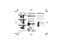
2.1 TERMINAL BLOCK [1]
1
7
13
2
8
14
9
15
4
10
16
5
11
17
6
12
18
3
0,5
Nm
Rear
terminal
cover
5.7 mm
0.22 in
Wire size
1 mm2 [2]
Terminals
18 M3 screw terminals
Option terminals
UL note
[1] Use 60/70 °C copper (Cu)
conductors only.
[2] Wire size 1 mm2
(18 AWG Solid/Stranded)
8
Tightening torque
0.5 Nm
Phillips screw
driver PH1
Flat blade screw
driver 0.8 x 4 mm
Ø
L
Pin connector
q 1.4 mm
0.055 in max.
Fork-shape
AMP 165004
Ø 5.5 mm - 0.21 in
Stripped wire
L 5.5 mm - 0.21 in
FX27.ed0
3-07-2008
15:52
Pagina 9
2 - Electrical connections
PRECAUTIONS
B
Despite the fact that the instrument
has been designed to work in an
harsh and noisy environmental
(level IV of the industrial standard
IEC 801-4), it is recommended to
follow the following suggestions.
B
2.2 SUGGESTED WIRE ROUTING
Conduit for supply and output cables
B
A
B BB
A
B
A
All the wiring must comply with the
local regulations.
The supply wiring should be routed away from the power cables.
Avoid to use electromagnetic contactors, power Relays and high
power motors nearby.
Avoid power units nearby, especially if controlled in phase angle
Keep the low level sensor input
wires away from the power lines
and the output cables.
If this is not achievable, use shielded cables on the sensor input, with
the shield connected to earth.
C
1
L
7
13
1
L
7
13
2
N
8
14
2
N
8
14
3
9
15
3
9
15
4
10
16
4
10
16
5
11
17
5
11
17
6
12
18
6
12
18
ED
C
C
ED
A = Supply
B = Outputs
C = Analog inputs
D = Analogue
Output
C
Serial Comm.s
E = Digital
input/output
Conduit for low level sensor cables
9
FX27.ed0
3-07-2008
15:52
Pagina 10
2 - Electrical connections
B
2.3 EXAMPLE OF WIRING DIAGRAM (HEAT COOL CONTROL)
Power supply
V
Supervision
~
Retransmission
Power
supply
[3] switch
RS485
RX/TX
0P4
4…20mA
Cooling
V
~
Fuse
[5]
PTC [4]
1
7
V~
Fuse
[5]
[6]
2
8
3
18V 9
10
15
16
OP2
5
11
17
6
12
18
TC
CT Current transformer 50 mA
V
Heating
10
~
[6]
14
OP2
OP1
4
13
OP3
~T
~
Fuse 2A
[6] V
Alarm
Notes:
1] Make sure that the power supply
voltage is the same indicated on
the instrument.
2] Switch on the power supply only
after that all the electrical connections have been completed.
3] In accordance with the safety regulations, the power supply switch
shall bring the identification of the
relevant instrument. The power
supply switch shall be easily accessible from the operator.
4] The instrument is is PTC protected. In case of failure it is suggested to return the instrument to the
manufacturer for repair.
5] To protect the instrument internal
circuits use:
- 2AT fuse for 220Vac relay outputs;
- 4 AT fuse for 110vac relay outputs;
6] Relay contacts are already protected with varistors.
Only in case of 24 Vac inductive
loads, use model A51-065-30D7
varistors (on request)
FX27.ed0
3-07-2008
15:52
Pagina 11
2 - Electrical connections
2.3.1 POWER SUPPLY
B
Switching power supply with multiple isolation and internal PTC
• Standard version:
nominal voltage:
100...240Vac (-15...+10%)
Frequency 50/60Hz
• Low Voltage version:
Nominal voltage:
24Vac (-25...+12%)
Frequency 50/60Hz or
24Vdc (-15...+25%)
• Power consumption 1.6W max.
Included
PTC
L
1
N
2
Supply
B
2.3.2 PV CONTROL INPUT
A For L-J-K-S-T thermocouple type
• Connect the wires with the
polarity as shown
• Use always compensation cable
of the correct type for the thermocouple used
• The shield, if present, must be
connected to a proper earth.
B For Pt100 resistance
thermometer
• If a 3 wires system is used, use
always cables of the same diameter (1mm2 min.) (line 20 Ω/lead
maximum resistance)
• When using a 2 wires system, use
always cables of the same diameter (1.5mm2 min.) and put a
jumper between terminals 5 and 6
C For ∆T (2x RTD Pt100) Special
A When the distance between
the controller and the sensor is
15 m. using a cable of 1.5 mm2
diameter, produces an error on
the measure of 1°C (1°F).
R1 + R2 must be <320Ω
Wire resistance
150Ω max.
5
6
B
5
b
6
A
12
A
R1
B
R2
A
5
6
For 3 wires only
Maximum
resistance/line 20Ω
Use wires of the
same length and
1.5 mm2 size.
Maximum resistance/line 20Ω
12
11
FX27.ed0
3-07-2008
15:52
Pagina 12
2 - Electrical connections
2.3.2 PV CONTROL INPUT
B
D
2.3.3 AUXILIARY INPUT
(option)
For mA, mV
mV mA
5
6
External
Shunt 2.5Ω
4…20mA
external shunt 2.5Ω
9 18V– [1]
6
• The input is active when the
logic state is ON, corresponding to the contact closed
• Primary coil 10A…100A
• Secondary coil 50mA default
100mA jumper selectable
• The input is inactive when the
logic state is OFF, corresponding to the contact open
17
5 watt burden resistor
0.5Ω for 1A secondary
transformer coil
0.1Ω for 5A secondary
transformer coil
CT
load
9 18V– [1]
9
10
18
50/100mA
11
10…100A
Com.
Transducer
5
6
external shunt
2.5Ω
[1] Auxiliary power supply for external
transmitter 18Vdc ±20% /30mA max.
without short circuit protection
12
NPN
C1 open collector
IL 1
~
D2 With 3 wires transducer
PV
B
For current transformer CT
Not isolated
For the measure of the load current (see page 34)
5
Transducer
2.3.4 DIGITAL INPUT
(option) (page 37)
Rj >10MΩ
D1 With 2 wires transducer
PV
B
Jumper for
100 mA
secondary
transformer coil
Isolated
contact
TTL
open
collector
FX27.ed0
3-07-2008
15:52
Pagina 13
2 - Electrical connections
B
2.3.5 OP1 - OP2 - OP3 OUTPUTS
The functionality associated to each of the OP1, OP2 and OP3 input is defined
during the configuration of the instrument index l(see page 18).
The suggested combinations are:
Control outputs [1]
A
B
C
D
E
F
Single
action
Single
action
Double
action
Double
action
Double
action
Valve
drive
OP1 - OP3
OP2 - L
OP2 - R
OP1
Heat
OP2-L
Heat
OP1
Heat
OP1
Heat
OP2-L
Heat
OP1
Open
OP2 output can be Relay (Std) or
logic.
The “jumper” on the auxiliary
board selects the output type:
Alarms
OP3
Cool
OP2-L
Cool
OP3
Cool
OP3
Close
AL2
AL3
OP2-R
OP3
OP1
OP3
Link Pins 1-2 for OP2-Relay
Link Pins 2-3 for OP2-Logic
OP2-R
[2]
Jumper
OP3
[2]
OP1
[2]
OP2-R
[2]
3
2
1
Auxiliary
board
Relay output
Logic output
Relay output
Notes
[1] Except for valve drive, each control output can be replaced by the OP4
analogue output. The replaced output is no more available.
[2] With heat/cool control and with valve drive control AL2 and AL3 share in
or mode the same output (the free one).
13
FX27.ed0
3-07-2008
15:52
Pagina 14
2 - Electrical connections
2.3.5-A SINGLE ACTION
RELAY CONTROL
OUTPUT
B
2.3.5-C DOUBLE ACTION
RELAY/RELAY CONTROL OUTPUT
Fuse
3
OP1
4
Varistor for
inductive load
24Vac only
2.3.5-B SINGLE ACTION
LOGIC CONTROL
B
OUTPUT
10
Static
relay
OP3
14
Coil of the
heat load
contactor
Load
11
Relay output
• SPST Relay N.O., 2A/250Vac
for resistive load, fuse 2AT
Logic output not isolated
• 0…5Vdc, ±20%, 30 mA max.
Coil of the
cool load
contactor
Varistor for
inductive load
24Vac only
2.3.5-D DOUBLE ACTION
RELAY/LOGIC CONTROL OUTPUT
Fuse
3
10
OP1
OP2
4
OP2
14
13
OP1
4
Coil of the
heat load
contactor
Fuse
3
Fuse
B
B
Static
relay
11
Varistor for
inductive load
24Vac only
Coil of the
heat load
contactor
2.3.5-E DOUBLE ACTION
LOGIC/RELAY CONTROL OUTPUT
10
OP2
11
Cool
load
Static
relay
Heat
load
B
Fuse
13
OP3
14
Varistor for
inductive load
24Vac only
Coil of the
cool load
contactor
FX27.ed0
3-07-2008
15:52
Pagina 15
2 - Electrical connections
2.3.5.F VALVE DRIVE
RELAY/ RELAY
CONTROL OUTPUT
3
OP1
4
2.3.6
B
ALARMS OUTPUTS B
e The outputs OP1, OP2 and OP3,
can be used as alarm outputs only
if they are not configured as control outputs.
Open
Vac
M
~
3
OP1
4
14
Coil of the
load alarm contactor
13
Valve drive P.I.D. without
potentiometer (open, close, stop)
• Galvanic isolation
500Vac/1 min
• 0/4…20mA, (750Ω or 15Vdc max.)
Fuse
Close
OP3
2.3.7 OP4 ANALOGUE
CONTROL OUTPUT
B
(option)
Fuse
15
OP2
16
Coil of the
load alarm contactor
Fuse
13
OP3
7
mA
OP4
Load
8
2.3.8 SERIAL
COMMUNICATIONS
B
(option)
• Galvanic isolation 500Vac/1 min
• Compliance to the EIA RS485
standard for Modbus/Jbus
A Please, read the user Manual:
“Serial communication and
configuration software”.
14
Coil of the
cool load
contactor
Varistor for inductive load
24Vac only
7
8
15
FX27.ed0
3-07-2008
15:52
Pagina 16
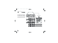
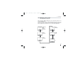
3 - Product coding
3
PRODUCT
CODING
The complete code is shown on
the instrument label. The informations about product coding are
accessible from the front panel by
mean of a particular procedure
described at section 4.2.2 page 21
1
2
3
3150
RUN
SP2 MAN
16
Instrument Label
Hard
B
C
D
L
M
N
Basic product code (hardware)
Configuration code (software)
FX27.ed0
3-07-2008
15:52
Pagina 17
3 - Product coding
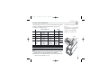
3.1 MODEL CODE
The product code indicates the specific hardware configuration of the instrument, that can be modified, by
specialized engineers only.
Basic
Model:
Accessories
A B C D - E 0 0 0 /
Configur.
I L M N
Power supply
100...240Vac (-15...+10%)
24Vac (-25...+12%) or 24Vdc (-15...+25%)
A
3
5
OP1 - OP3 Outputs
Relay - Relay
B
1
Serial Communications
Not fitted
RS485
Modbus/Jbus protocol
Digital input
Options
None
Valve drive control output
Current transformer input (CT)
Transmitter Power Supply (P.S.)
Transmitter P.S. + Cont. control output
Transmitter P.S. + CT
Transmitter P.S. + Cont. control + CT
None
Valve drive control output
Transmitter Power Supply
Transmitter P.S. + CT
None
Valve drive control output
CT
Analogue control output
Analogue control output + CT
C
0
0
0
0
0
0
0
5
5
5
5
9
9
9
9
9
D
0
1
3
6
7
8
9
0
1
6
8
0
1
3
7
9
Special functions
Not fitted
Start up + Timer
E
0
2
17
FX27.ed0
3-07-2008
15:52
Pagina 18
3 - Product coding
3.2
CONFIGURATION CODING
The configuration code consists of
4 digits that identify the operating characteristic of the controller,
as chosen by the user.
Section 4.6 at page 35 reports the
instructions how to set a new configuration code.
I L M N
2002
Conf
The configuration code can be displayed on the front panel, following the instructions at page 21 section 4.2.2.
Input type and range
TR Pt100 IEC751
TR Pt100 IEC751
TC L Fe-Const DIN43710
TC J Fe-Cu45% Ni IEC584
TC T Cu-CuNi
TC K Chromel -Alumel IEC584
TC S Pt10%Rh-Pt IEC584
DC input 0…50 mV, linear
DC input 10…50 mV, linear
Custom input and range [1]
I
0
1
2
3
4
5
6
7
8
9
[1] For instance, other thermocouples types, ∆T (with 2 PT 100), custom
linearisation etc.
Control mode
-99.9…572.0 °F
-328…1112 °F
32…1112 °F
32…1112 °F
-328…752 °F
32…2192 °F
32…2912 °F
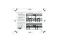
Output configuration [2]
Control OP1 / alarm AL2 on OP2
PID
Control OP2 / alarm AL2 on OP1
Control OP1 / alarm AL2 on OP2
On - Off
Control OP2 / alarm AL2 on OP1
Control OP1- OP3 / alarm AL2 on OP2
Heat/Cool
Control OP1- OP2 / alarm AL2 on OP3
action
Control OP2- OP3 / alarm AL2 on OP1
P.I.D. valve drive Control OP1-OP3/alarm AL2 on OP2
L
0
1
2
3
6
7
8
9
[2] Each control output can be replaced by the OP4 analogue output.
The replaced output is not more available (see page 34).
Control action type
Reverse (single action)
Direct (single action)
18
-99.9…300.0 °C
-200…600 °C
0…600 °C
0…600 °C
-200 …400 °C
0…1200 °C
0…1600 °C
Engineering units
Engineering units
M
Linear Cool (Heat/Cool double action) 0
On-Off Cool (Heat/Cool double action) 1
FX27.ed0
3-07-2008
15:52
Pagina 19
3 - Product coding
A
If, when the controller is powered
up for the first time, the display
shows the following message
1
2
3
9999
Conf
it means that the controller has
not been configured yet.
The controller remain in stand-by
until the configuration code is set
correctly (see chapter 4.6 page 35).
Alarm 2 type and function
Not active
Sensor break alarm / Loop Break Alarm
active high
Absolute
active low
active high
Deviation
active low
active out
Band
active in
active during ON output state
Heater break
by CT [3]
active during OFF output state
N
0
1
2
3
4
5
6
7
8
9
Alarm 3 type and function
Disabled or used by Timer
Sensor break alarm / Loop Break Alarm
active high
Absolute
active low
active high
Deviation
active low
active out
Band
active in
active during ON output state
Heater break
by CT [3]
active during OFF output state
O
0
1
2
3
4
5
6
7
8
9
For alarm 3 type and function see page 34
Note
[3] Only with CT options.
19
FX27.ed0
3-07-2008
15:52
Pagina 20
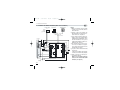
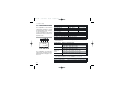
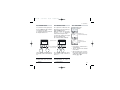
4 - Operations
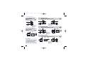
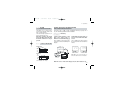
4
OPERATIONS
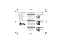
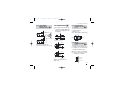
4.1.A KEYS FUNCTIONS AND DISPLAY IN OPERATOR MODE
When the measured When the measured
PV control input value is greater than value is less than the
sensor high range
sensor low range
in engineering
units
Output status OP1 output ON
LEDs OP2 output ON
(red): OP3 output ON
Start-up/Timer
running (green)
Stand-by
Setpoint enabled
(green): steady
Fuzzy Tuning running
(green):
blinking
Manual
operating mode
(green): steady
274.8
1
2
3
RUN
SP2 MAN
Operating
Setpoint
(At the power
on the target
Setpoint value
is displayed
for 3 seconds)
275.0
Menu
access
Setpoint
setting
Enter key for
selection and
value setting
confirmation
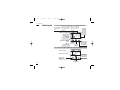
4.1.B KEYS FUNCTIONS AND DISPLAY IN PROGRAMMING MODE
Parameter value
35.0
1
2
3
p.b.
Parameter mnemonic
A/M
Access to the
menu for:
- configuration
- parameter setting
20
Values
modification
Enter key for
selection and
value setting
confirmation
FX27.ed0
3-07-2008
15:52
Pagina 21
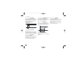
4 - Operations
4.2
DISPLAY
4.2.1 OF THE
PROCESS VARIABLES
During the operation, the parameters values cannot be modified by the user
274.8
275..0
274.8
°C
Local
Setpoint
(manual)
Operator mode
275.0
274.8
Engineering
units [1]
274.8
Out
47
t.Cur
OP1
output
(auto) [2]
3150
Hard
Load
current [3]
Conf
00A
33
tM.r.
Engineering
units [1]
°C
2002
Note
[1] See table page 37
[2] This display is not presented
if the instrument has been configured as an On - Off controller
[3] Value in Ampere. Only with CT
option (see page 34)
[4] Only with Timer option selected
(see page 42)
Operator
mode
275..0
63.4
s.p.
4.2.2 OF THE CONFIGURATION
CODES
Timer
remaining
time [4]
Basic
product code
(see page 17)
Configuration
code
(see page 18)
Software
release
rel.
21
FX27.ed0
3-07-2008
15:52
Pagina 22
4 - Operations
4.3 PARAMETER SETTING
4.3.1 NUMERIC ENTRY
(i.e. the modification of the Setpoint value from 275.0 to 240.0 )
Operator
mode
Press $ or % momentarily to
working Setpoint
change the value of 1 unit every
displayed
274.8
275.0
push.
Continued pressing of $ or %
changes the value, at rate that doubles every second. Releasing the button the rate of change decreases.
In any case the change of the value
stops when it has reached the
max./min. limit set for the parameter.
In case of Setpoint modification:
press $ or % once to display
the local Setpoint instead of working Setpoint.
To evidence this change the display flashes once. Then the
Setpoint can be modified
274.8
Local
Setpoint display
275.0
—Decrease
Setpoint
modification
274.8
230.0
—Increase
274.8
240.0
after 2 s
°C
240.0
22
Setpoint entry.
The operation is
acknowledged by
one flash of the
display.
FX27.ed0
3-07-2008
15:52
Pagina 23
4 - Operations
4.3.2 MNEMONIC CODES SETTING
(e.g. configuration see page 35)
Press the $ or % to display the next or previous mnemonic for
the selected parameter.
Continued pressing of $ or % will display further mnemonics at a
rate of one mnemonic every 0.5 s. The mnemonic displayed at the time
the next parameter is selected, is the one stored in the parameter.
°C
Unit
°f
Unit
°C
Unit
Engineering
Units
Degree
Centigrade
Degree
Fahrenheit
°f
Unit
none
Unit
Degree
Fahrenheit
no units
defined
Degree
Centigrade
ph
Unit
Ph
23
FX27.ed0
3-07-2008
15:52
Pagina 24
4 - Operations
4.3.3 KEYPAD LOCK
4.3.4 OUTPUTS LOCK
To lock/unlock the keypad press
the keys í and è simultaneously for 2 seconds.
To confirm the keypad lock/unlock
the display flashes once.
The outputs are switched to the
OFF status by pressing the keys
è and %together.
When the outputs are locked, the
message #Off
is displayed
instead of the Setpoint value.
To unlock the outputs press again
the keys simultaneously
(the Soft-start will be enabled).
274.8
operator mode
274.8
275.0
OFF
Press simultaneously
for 2 seconds
The keypad lock/unlock can be
achieved by serial communications
too.
The outputs lock/unlock can be
achieved by serial communications too
A The
AThe outputs
keypad lock is maintained in case of power
failure.
4.3.5 AUTO / MAN
274.8
Operator
mode
275..0
Auto
A.Man
Man
MAN
A.Man
Select M
# an
to switch to manual mode
# uto
Select A
to switch to automatic
mode
• Press è to confirm. Back to
operator mode.
• The { led shows the manual
mode status.
• When manual mode is active,
the Setpoint display shows the
output value, that can be modified by $ %
lock/unlock is
maintained in case of
power failure.
24
FX27.ed0
3-07-2008
15:52
Pagina 25
4 - Operations
4.4 PARAMETERISATION
Auto/Man
selection
(see page 24)
274.8
Parameter
mnemonic
Parameter
value
275..0
35.0
Operator mode
A.Man
p.b.
Prameter
menu
selection
Values
modification
Modification/
selection
enter
A
The parameter setting procedure
has a timeout. If no keys are
pressed for, at least, 30 seconds,
the controller switches back, automatically, to the operator mode.
After having selected the parameter or the code, press $ and %
to display or modify the value (see
page 22) The value is entered when
the next parameter is selected, by
pressing the è key.
Pressing the í key, the next group
of parameters is presented on the
display.
25
Timer run/stop
(if option installed)
Note
[1] It is not presented if the controller has been configured
with alarm n° 2 not active or
of sensor break type. Digit
N/M of the configuration
é
code is assigned to 0 or 1.
[2] These values are not automatically stored on the P.I.D.
menu parameters P.b,. t.i, t.d.
é 1.00
0
é
A3s.p
AL3 alarm threshold [1]
(see page 29)
é
Proportional band
(P.I.D. algorithm only)
0.5…999.9% of span
Derivative time
(P.I.D. algorithm only)
0.5…999.9% of span
20
t.c.
Cycle time
(Time proportioning only)
1…200 s
é 1:00
5:0
t.i.
t.d.
é
5:0
p.b.
t.run
Integral time
(P.I.D. algorithm only)
0ff / 0.1…100.0 min
O.C.
Overshoot control
(P.I.D. algorithm only)
0.01…1.00
FX27.ed0
3-07-2008
15:52
Pagina 26
4 - Operations
é
33
pAss
5000
PARAMETER MENU
é
Password entry
only if Code value
≥5000
(see pages 35…37)
0
1st GROUP
A2s.p AL2 alarm threshold [1]
(see page 29)
Code entry
5000... 9999
Must be equal to the
value of the parameter
Code
NO
é
OK
YES
60
MU.tM
é
é
1.0
Motor travel time
(Valve drive PID
algorithm only)
15…600 s
0.5
MU.hY
é
é
r.C.Ga
t.c. C
hy. C
é
Cool cycle time
(heat/cool with cool time
propotional PID only)
1…200 s
Op. H
0.5
Minimum output step
(Valve drive PID
algorithm only)
1.1…6.0 %
20
é100.0
Cool relative gain
(heat/cool configuration only)
0.1…10.0
é100.0
Cool control output
Cool output hysteresis
(On-Off control only)
0.1…10.0% range
0.5
d.bnd
limit
Op.HC high
(heat/cool PID configuration
only) 10.0…100.0%
é
Dead band
(heat/cool configuration only)
-10.0…10.0%
0.5
hy.
Back to the
26
Control output high limit
(PID algorithm only)
10.0…100.0%
Control output hysteresis
(On-Off control only)
0.1…10.0% of span
1st parameter group
FX27.ed0
3-07-2008
15:52
Pagina 27
4 - Operations
tune
2nd GROUP
Tuning run/stop
(PID algorithm only)
é
1
tiMe
é
ADPT
Continuous Tuning start
(adaptive tuning)
(PID algorithm only)
PrGh
éH.érange
Timer setting
(if option installed)
1…9999 s or min
s.p. H
0
s.p. 2
é
0
Stand-by Setpoint
s.p. l…s.p. H
s.p.s.U
é Off
p.b. a
Calculated Proportional
band [2] (display only)
(available when adaptive
tuning is selected)
sl.u
é
T.i. A
sl.d
t.h.s.U
t.d. A
s.p. l
Start-up hold time
(if option installed)
0…500 min
é100.0
Setpoint ramp down
0ff/0.1…999.9
digit/min
éL.érange
Calculated derivative
time [2] (display only)
(available when adaptive
tuning is selected)
Start-up Setpoint
(if option installed)
s.p. l…s.p. H
1
Setpoint ramp up
0ff/0.1…999.9
digit/min
é Off
Calculated Integral Time
[2] (display only)
(available when adaptive
tuning is selected)
Setpoint high limit
s.p. l…high range
é
Op.Hs
Setpoint low limit
Low range… s.p.
H
Output high limit during
Start-up
(if option installed)
5.0…100.0%
0.5
A2hy
AL2 hysteresis
0.1…10.0% of span [1]
27
FX27.ed0
3-07-2008
15:52
Pagina 28
4 - Operations
pass
Password entry
only if Code value
<5000 (see pages 35…37)
Direct access
to the configuration
(pages 35 … 37)
énone
é
A2L.b
0.5
A3hy
énone
A3L.b
é Off
Input shift
AL2 latching and
blocking functions
none / Ltch
bloc / Lt.bL
In.sh -60…60 digits
é Off
d.Err
AL3 hysteresis
0.1…10.0% of span [1]
é Off
t.Fil
Filter time constant
1…30 s or. Off
Addr
Communication address
(if option installed)
0ff/ 1…247
Soft-start output value
algorithm and
st.Op t.(PIDMod
=0ff)
é
LBA delay
(see page 31)
0ff= sensor break
1…9999 s LBA
1
é Off
AL3 latching and
blocking functions
none / Ltch
bloc / Lt.bL
é Off
t.LbA
é
Error dead band
(PID algorithm only)
0ff/0.1…10.0 digits
1
0ff/0.1…100.0%
Soft-start
time
st.tM activation
(only if st.Op different than
0ff) 1…9999 s
é
0
safety value
0.0…100.0%
sa.Op Output
(-100.0…100.0% for
heat/cool)
Back to the
2nd parameter group
28
FX27.ed0
3-07-2008
15:52
Pagina 29
4 - Operations
4.5
Absolute alarm
PARAMETERS
FIRST GROUP
The controller parameters have
been organised in group, according to their functionality area.
AL2 alarm
threshold
AL3 alarm
threshold
The alarm occurrences handle the
OP1, OP2 and OP3 outputs, in different ways, according to the configured types of alarms, as illustrated.
A
# 2s.p
A
# 3s.p
On Active
Off high
On
Off
Active
low
hy
Low range Alarm threshold
High range
Deviation alarm
On Active
Off high
SP
On
Off
Active
low
hy
- low range
+ high range
Alarm threshold
Band alarm
With double action control output, AL2 and AL3 share in or
mode the same output (the free
one) (see table on page 13).
SP
On
Off
hy
Sensor break or input disconnection
Sensor
hy
Full scale
Active
in
Full scale
Alarm threshold
Visualisation
over-range
Proportional
band
This parameter specifies the proportional band coefficient that multiplies the error (SP - PV)
#p.b.
T
under-range
29
On Active
Off out
#t.i.
Integral time
It is the integral time value, that
specifies the time required by the
integral term to generate an output
equivalent to the proportional term.
When Off the integral term is not
included in the control algorithm.
Derivative
time
It is the time required by the proportional
term P to repeat the output provided by
the derivative term D. When Off the
derivative term is not included in the
control algorithm.
#t.d.
Control output
cycle time
Cycle time
cool
It’s the cycle time of the logic control output. The P.I.D. time proportional control output is provided
through the pulse width modulation of the digital waveform.
# .c.
t
#t.c. C
Overshoot
control
(Automatically disabled when the
adaptive tuning is running).
This parameter specifies the span of
#O.C.
FX27.ed0
3-07-2008
15:52
Pagina 30
4 - Operations
action of the overshoot control.
Setting lower values (0.99 —> 0.01) the
overshoot generated by a Setpoint
change is reduced. The overshoot
control doesn’t affect the effectiveness of the P.I.D. algorithm. Setting 1,
the overshoot control is disabled.
Heat/Cool
dead band
This parameter specifies the width
of the deadband between the Cool
and the Heat channel.
#d.bnd
Motor travel time
It provides the time
required to the motor positioner to
go from the 0% position to 100%
#MU.tM
Minimum output
step
It specifies the minimum allowed time
of activation of the output to a motor
positioner that produces a sensible
effect. It is related to the deadband
of the positioner.
#MU.hy
Control output
high limit
Cool output
high limit
It specifies the maximum value the
control output can be set
# p. H
O
#Op.HC
30
# y.
h
#hy. C
Control output
hysteresis
Cool output
hysteresis
Hysteresis of the threshold
SP
On
Off
hy
Control or alarm output hysteresis
span, set in % of the full scale.
AL2
alarm hysteresis
AL3
alarm hysteresis
Hysteresis of the threshold of both
the alarms, that activate OP1 and
OP2 control output. It is specified
as a % of the full scale.
A
# 2hy
A
# 3hy
# .p. l
s
#s.p. H
Setpoint
low limit
Setpoint
high limit
Low / high limit of the Setpoint value.
SECOND GROUP
Stand-by
Setpoint
Used by Timer function too.
#S.P. 2
Setpoint
ramp up
Setpoint
ramp down
This parameter specifies the maximum rate of change of the Setpoint
in digit/min. When the parameter is
Off, this function is disabled.
# l. u
s
#sl. d
AL2, AL3
latching
and blocking
functions
For each alarm it is possible to
select the following functions
none none
Ltch latching
bloc blocking
Lt.bL both latching and blocking
#A2L.b
#A3L.b
FX27.ed0
3-07-2008
15:52
Pagina 31
4 - Operations
L
# tch
ALARM
ACKNOWLEDGE FUNCTION
The alarm, once occurred, is presented on the display until to the
time of acknowledge.
The acknowledge operation consists in pressing any key.
After this operation, the alarm
leaves the alarm state only when
the alarm condition is no longer
present.
b
# loc
ALARMS WITH LBA (LOOP BREAK ALARM)
AND SENSOR BREAK OPERATION
Select the code 1 on n or o configuration indexes (see pages 18 or
19). The following parameter is then available:
#t.LbA
LBA delay
Setting a value between 1 and
9999 s the alarm works as
LBA+Sensor break with delay [1]
This condition is shown by means
a red led as well as the blinking PV
display.
START-UP DISABLING
Ramp down
____
8888
274.8
Disable
∆SP
SP
On
Off
Setting OFF the alarm works as
Sensor break with immediate
action.
This condition is shown by means
the red led of the selected alarm as
well as:
275.0
275.0
8888
---or
275.0
OP1
Start-up
Ramp up
SP
∆SP
mA
Disable
°C
Note [1] In case of sensor break, condition, the alarm action is immediate.
On
Off
Start-up
∆SP Threshold = SP ± range
When the cause of the alarm disappears, the alarm status stops.
31
FX27.ed0
3-07-2008
15:52
Pagina 32
4 - Operations
Input filter
time constant
Time constant, in seconds, of the RC
input filter applied to the PV input.
When this parameter is set to Off
the filter is bypassed.
t
# .fil
Filter response
100%
63,2%
PV
Soft-start control
output value
Value of the control output during
the Soft-start activation time.
S
# t.OP
Soft-start
activation time
Time duration (starting from the
power on) of the Soft-start function.
s
# t.tM
OP
100%
0 t.Fil
I
# n.sh
Time
Error Dead
Band
Inside this band for (PV - SP), the control output does not change to protect
the actuator (output Stand-by).
32
Soft-start
phase
Input shift
This value is added to the measured
PV input value. Its effect is to shift the
whole PV scale of up to ± 60 digits.
d
# .Err
#St.OP
Start up
#St.tM
Time
Output
Safety Value
Output Value in case of input
anomaly.
S
# a.OP
Controller
address
the address range is from 1 to 247
and must be unique for each controller on the communication bus
to the supervisor.
When set to Off the controller
is not communicating
A
# ddr
FX27.ed0
3-07-2008
15:52
Pagina 33
4 - Operations
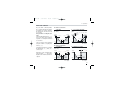
HEAT COOL CONTROL
By a sole P.I.D. control algorithm,
the controller handles two different outputs, one of these performs
the Heat action, the other one the
Cool action.
It is possible to overlap the outputs.
The dead band parameter d
# b
. nd,
is the zone where it is possible to
separate or overlap the Heat and
Cool actions.
The Cool action can be adjusted
using the relative cool gain parameter #r.C.Ga.
To limit the Heat and Cool outputs
the parameters 0
# p. H and 0
# p.HC
can be used.
A
Heat /Cool actions
separated
Insert positive #d.bnd
(0…10%)
100%
value
-100%
#Op. H
C Cool action adjusting
Example with different relative cool
gains
=2.0 #r.C.Ga 0.1…10.0
100%
=1.0
=0.5
#d.b.nd
#d.b.nd
Heat
0% output
100%
-100%
#Op.HC
Cool
output
50%
0%
PID output
Heat /Cool actions
overlapped
Insert negative #d.bnd value
(-10…0%)
Heat
0% output
100%
Cool
output
50%
0%
PID output
B
D
On-Off Cool action
#hy. C
-100%
100%
#Op. H
When there is an overlap, the displayed output # OUt shows the
algebric sum of the Heat and Cool
outputs.
On
100%
#Op.HC
#d.b.nd
#d.b.nd
0%
Heat
output
100%
Cool
output
50%
0%
PID output
Heat
0% output
100%
Cool
output
50%
Off
0%
PID output
33
FX27.ed0
3-07-2008
15:52
Pagina 34
4 - Operations
ANALOGUE CONTROL
OUTPUT OP4
When configured, the analogue
control output excludes the
corresponding time proportioning control output automatically.(see page18)
(e.g. if code l = 0 and
# r t. h = M.U.. the OP1 is not
yet available)
r
# etr
CURRENT TRANSFORMER INPUT
With CT option it is possible to display the load current and set an
alarm threshold.
It is possible to set AL2 or AL3
(index 8 and 9) to have an alarm
when, during the ON time of the
time proportional output, the load
current is less then the specified
threshold or, during the OFF time,
there is at least 3% of full scale
120 ms
Control output
selection
Not used
Heat (single action)
Cool
With analogue control output
or t
# c C are not present.
t
# c
OP1
120 ms
OFF
ON
ON
t.Cur
A2s.p
Load current
none
M.U.
M.U. C.
Example:
CT input on OP1, alarm on AL2 during on time (configuration digit N = 8)
Analogue control
output range
0=20 / 4=20
#rt.H
load current
The alarm condition must be longer
than 120 ms to set the alarm.
During the OFF time the parameter tCur latches the last on time
current value
3%
AL2
OFF
ON
OFF
ON
OFF
34
FX27.ed0
3-07-2008
15:52
Pagina 35
4 - Operations
4.6 CONFIGURATION
274.8
The configuration of the controller
is specified through a 4 digit code
that defines the type of input, of
control output and of the alarms.
(sect. 3.2 page 18)
Parameter
value
275..0
Operator mode
Auto / Man
selection
(see page 24)
A.Man
Timer run/stop
(if option
installed)
t.run
Parameter
mnemonic
200.2
Conf
Values
modification
Configuration
Enter key for
menu access
selection and
value setting
confirmation
Press $ or % to display the
next parameter or the next code
and change its value.
The new value entered is stored into
the controller when the next parameter is selected by pressing è.
Pressing the í the next group
of parameters is displayed.
35
rtH
Control output selection
(only if installed)
none Not used
M.U Heat M.U. C Cool
prot
Comm.s protocol
(only if communication is
installed)
M.bu5 / jbus
Ht.f.s
CT primary high range
(only if installed)
10…200 A
baud
Baude rate
(only if comm. is installed)
Password [2]
0…9999
33 di default from factory
retr
Code
1200/2400
4800/9600
Analogue control
output range
(only if installed)
0=20 / 4=20 mA
FX27.ed0
3-07-2008
15:52
4 - Operations
Pagina 36
CONFIGURATION MENU
A2s.p
pAss
5000
1st GROUP
tune
2nd GROUP
Password entry
only if Code value
≥5000
Code entry
from 5000 to 9999
Must be equal to the
value of the parameter
Direct access
to the configuration
Code
NO
OK
YES
Unit
Engineering units
(see table 1)
Entry of digits I-L-M-N
of the configuration code
(chapter 3.2 page 18 and 19)
I L M N
IL.Fn
Digital input
function
(only if installed)
(see table 2)
sc.d.d
No. of decimals
(linear scale only)
0…3
t.Mod
Timer/Start-up
operating mode
(only if installed)
(see page 40 and table 1
page 42)
Timer Action
(only if t.Mod not equal
to Off or to 1)
(see table 2 page 42)
sc.lo
Low range [1]
(linear scale only)
-999…9999
sc.Hi
High range [1]
(linear scale only)
-999…9999
t.Act
36
2002
AL3 configuration code
(see table O, page 19)
Conf
Con2
FX27.ed0
3-07-2008
15:52
Pagina 37
4 - Operations
pass
33
Password entry
only if Code value <5000
Code entry
from 0 to 4999 (33 default from factory)
The entered password must correspond to
the one store in the Code parameter.
OK
YES
NO
Table 1 - Supported Engineering Units.
Centigrade degrees*
Fahrenheit degrees *
nessuna
mV
Volt
mA
Ampere
Bar
PSI
Rh
pH
*
A
°C
°f
none
nU
U
MA
A
bAr
psI
rh
ph
For inputs from thermocouple or
resistance thermometer, the choice
is between °C and °F only.
Direct access to the configuration
Table 2- Digital input functions
A From parameterisation (see page 28).
B At the first power on when the
controller is not configured:
9999
Conf
In this situation, the controller has its outputs and inputs not active.
This situation ends when a correct configuration code is entered.
Not used
Keypad lock
Auto/Man
Stand-by Setpoint
Timer launch
Off
keb.I
A.Man
s.p. 2
str.t
Notes
[1] Minimum Range 100 digits.
[2] To avoid free parameter access
insert 5000…9999
37
FX27.ed0
3-07-2008
15:52
Pagina 38
5 - Automatic tuning
5
AUTOMATIC
TUNING
Two tuning methods are provided:
• Initial one shoot Fuzzy-tuning
• Continuous, self learning
Adaptive Tuning
The Fuzzy-Tuning allows the calculation of the optimal P.I.D. terms parameters, monitoring the response of
the process to disturbances.
The controller provides 2 types of
“one shot” tuning algorithm, that
are selected automatically according to the process condition when
the operation is started.
Step response
This type is selected when, at the
start of the autotune operation, the
PV is far from the Setpoint of more
than 5% of the span.
This method has the big advantage
of fast calculation, with a reasonable
accuracy in the term calculation.
Natural frequency
This type is selected when the PV is
close to the SP Setpoint.
This method has the advantage of
38
a better accuracy in the term calculation with a reasonable speed
calculation.
The Fuzzy Tuning determines
automatically the best method to
use to calculate the P.I.D. term,
according the process conditions.
274.8
275..0
press until
stop
tune
Step response
To start
select
strt
SP
Setpoint change
Operator
mode
End of the tuning
operating and setting of
the new calculated
terms.
PV variable
Start of autotune
operation
strt
tune
To stop
select
stop
Control output
Natural frequency
tuning start
PV variable
End of the tuning
operating and setting of
the new calculated
terms.
Control output
The green led { blinking goes on
when the Fuzzy Tuning is in
progress. At the end of this operation, the calculated P.I.D. terms parameter are stored and used by the
control algorithm and the controller
goes back to the operator mode.
The green led { becomes off.
FX27.ed0
3-07-2008
15:52
Pagina 39
5 - Automatic tuning
The self-learning Adaptive Tuning
is not intrusive. It doesn’t affect the
process, at all, during the phase of
calculation of the optimal terms
parameters.
Continuous Adaptive Tuning
Perturbation
New
parameters
It is particularly suitable for controlling process whose control
characteristics change with
time or are not linear in relation
to the Setpoint values.
It does not require any operation by
the user. It is simple and works fine:
it samples continuously the process
response to the various perturbations, determining the frequency
and the amplitude of the signals.
On the basis of this data and their
statistical values, stored in the
instrument, it modifies automatically
the P.I.D. term parameters.
It is the ideal for all applications
where it is required to change continuously the P.I.D. terms parameters, in order to adjust the P.I.D. to
the changes of the process
dynamic conditions.
274.8
In case of power off with the
Adaptive Tuning enabled, the
values of the P.I.D. terms parameters are lost. At the power on
the Adaptive Tuning starts automatically and computes again
the values of the P.I.D. terms
parameters.
Stop
275..0
Operator
mode
press until
press è
tune
stop
Adpt
strt
Adpt
To start
select
strt
To stop
select
stop
39
FX27.ed0
3-07-2008
15:52
Pagina 40
6 - Special functions
6
SPECIAL
FUNCTIONS
Two special functions are available:
6.1 Start-up
6.2 Timer
In order to have the above functions the product code digit E must
be 2 (see page 17)
To select these functions use the
parameter:
t
# .Mod
Timer/Start-up
operator mode
(see page 36).
A Selecting
Timer or Startup, the Soft-start function
is disabled, therefore the
parameters # s t. O p and
# s t. t M will not be shown
(see page 27)
6.1
START-UP FUNCTION
By means of this function it is possible to manipulate the control
output when the controller is
switched on.
To configure
Start-up
function the
parameter
“Timer/Startup operating
mode” must be set to #
1.
Three parameters are associated
to the Start-up function, they
appear on the second group.
(see page 27)
1
t.Mod
#s.p.sU
#t.h.sU
O
# p.Hs
40
Start-up
Setpoint
(s.p. l…s.p.
H)
Start-up
hold time
(0…500 min.)
Output
high limit
(5.0%…100.0% min)
The Start-up function includes
three phases:
1st “Limy” - The control output is
limited to the #Op.Hs
2nd “Hold” - The process variable
is maintained to the Start-up
Setpoint for the time fixed by
the parameter #t.h.s.U
3rd “Off” - When the #t.h.s.U time
is elapsed the process variable
is maintained to the working
Setpoint.
Whether the process variable, for
any reason (e.g. load change),
decreases at a value lower than (
#s.p.sU - 40 digits), the Start-up
function starts again from the
“Limy” phase.
When the Start-up is in Hold phase,
if the local Setpoint becomes lower
than the Start-up Setpoint or if the
operating mode changes to manual, the Start-up function passes
to the “Off” phase.
FX27.ed0
3-07-2008
15:52
Pagina 41
6 - Special functions
There are two possibilities:
A Start-up Setpoint # s p. s U
lower than the local Setpoint.
The “Hold” phase starts when
the process variable PV
achieves the #sp.sU (with a
tolerance of 1 digit).
B Start-up Setpoint #sp.sU
greater than or equal to the
local Setpoint.
When the process variable PV
achieves the local Setpoint (with a tolerance of 1 digit), the Start-up function
passes directly to the “Off” phase.
If, at the controller power-on, the
process variable PV is greater than
the lowest between the s
# p.sU and
the working Setpoint , the next phase
(“Hold” or “Off”) will be executed
instead of the “Limy” phase.
During the
“Limy” and
“ H o l d ” phasRUN
es the Ö led
is on.
A
#s.p.sU < local Setpoint SP
power-on
noise
Setpoint SP
PV
#t.h.s.U
1 digit
#t.h.s.U
#sp.s.U
40 digit
OP=Op.H5
with TC = 25%
1sec min.
st
nd
1 “Limy” 2 “Hold”
B
3rd “Off”
1st “Limy” 2nd “Hold”
3rd “Off”
#s.p.sU < local Setpoint SP
power-on
PV
1285
#sp.s.U
1 digit
noise
Setpoint SP
40 digit
420
Start-up
Setpoint
OP=Op.H5
con TC = 25%
1sec min.
st
1 “Limy”
3rd “Off”
1st “Limy”
3rd “Off”
41
FX27.ed0
3-07-2008
15:52
Pagina 42
6 - Special functions
6.2
TIMER FUNCTION
To use AL3 in addition to this function, set the parameter C
# on2 (AL3
configuration code) is set to #
0..
A The Timer can’t be enabled
with Heat/Cool control.
The two following parameters (see
page 36) must be set to select one of
the six possible types of Timer.
Timer/Start-up
operating mode
By this parameter can be defined:
- the counting start time
- the control output status at the end
of the counting
t
# .Mod
Table 1
Timer counting mode
Value
Counting start time End mode
When inside the Control mode 2
band
Output to 0
3
Control mode 4
When launched
Output to 0
5
When launched.
Control mode 6
Control disabled
When launched
Control mode
stand-by Setpoint
42
7
Timer
Action
By this parameter can be defined:
- the time units
- the starting mode
- the OP3 status when the timer
is running.
When the timer is not running, the
OP3 takes the opposite status.
t
# .Act
Timer
setting
(1…9999 s/min)
Stand-by
Setpoint
(only for t.Mod = 7) (s.p. l…s.p.
t
# iMe
#s.p. 2
6.2.1. DISPLAY
850
Table 2
Time units
Seconds
Minutes
Starting
mode
Manual by
keypad
Auto at the
power on [2]
Manual by
keypad
Auto at the
power on [2]
[1]OP3
Value
status
Off
0
On
1
Off
2
On
3
Off
4
On
5
Off
6
On
7
[1] If used by Timer
[2] Using this selection, manual starting
mode is possible too.
After the Timer configuration the
following parameters will be shown
on the second parameters group.
(see page 26)
H)
RUN
850
When the Timer is running, the led
Ö is on.
850
End
When the Timer ends, the Setpoint
display shows alternatively the message #End
and the Setpoint
value until a key is pressed.
FX27.ed0
3-07-2008
15:52
Pagina 43
6 - Special functions
When the timer is running it is
always possible to see the remaining time and to modify it.
850
RUN
850
Operator mode
and Timer running
Press until
234
RUN
Remaining time.
6.2.2 TIMER STARTING
6.2.3 POWER FAILURE
Depending on the Timer action
#t.act selection, there can be two
different starting ways:
- Automatic at the power on
- Manual by keypad, serial communications or digital input.
To start/stop the Timer:
If there is a power failure during
the Timer execution, the value of
the elapsed time is lost.
350
Operator mode
350
tM.r.
Press until
Counting stop.
234
RUN
Remaining time value
t.run
To start
select strt
tM.r.
Value change
60
RUN
stop
tM.r.
0
If set to #
the timer ends
strt
t.run
Press the key
Depending on Timer action
#t.act selection, when the controller restarts you can have two
different situations:
• with automatic mode
(t
# a
. ct = 2,3,6,7), the Timer
function starts again and the
counting time is reinitialised.
• with manual mode
( #t.act = 0,1,4,5), the control output is forced to zero if
t
# Mod = 3 e 5; otherwise the
control action restarts using the
working Setpoint
To stop
select stop
è
to confirm
43
FX27.ed0
3-07-2008
15:52
Pagina 44
6 - Special functions
6.2.4 TIMER COUNTING MODES
A Counting start time inside
the band, end in control
mode.
B Counting start time inside
the band, end with control
output forced to zero.
C Counting start time = timer
launch time, end in control
mode.
The time counting starts only when the
error is inside a ± 1 digit band. The control action is not affected by the Timer
function.
The time counting starts only when the
error is inside a ± 1 digit band. At the end,
the control output is forced to zero. [1]
The time counting starts when the timer
is launched. The control action is not
affected by the Timer function.
Timer launch
#tiMe
#t.Mod = 2
Setpoint
Timer launch
#tiMe
#t.Mod =3
Setpoint
Process
variable PV
±1 digit
band
Output OP
Process
variable PV
±1digit
band
#t.Mod = 4
Process
variable PV
Output OP
OP3
[1] When the Timer is not running the control output is forced to zero, also before the
Timer launch
44
#tiMe
Setpoint
Output OP
OP3
Timer launch
OP3
FX27.ed0
3-07-2008
15:52
Pagina 45
6 - Special functions
D Counting start time = timer
launch time, end with control
output forced to zero.
E No control action during
the counting time.
F Control action with stand-by
Setpoint during the counting
time
The time counting starts when the timer
is launched. At the end, the control output
is forced to zero. [1]
The time counting starts when the timer
is launched and the control output is
forced to zero. At the end, the control
action starts.
The time counting starts when the timer
is launched and the control action use the
Stand-by Setpoint. At the end, the control
action use the working Setpoint.
Timer launch
Timer launch
#tiMe
#t.Mod = 5
Setpoint
#tiMe
#t.Mod = 6
Setpoint
Process
variable PV
Process
variable PV
Output OP
#tiMe
#t.Mod =7
Setpoint
Process
variable PV
#s.p. 2
Output OP
Output OP
OP3
Timer launch
OP3
OP3
[1] When the Timer is not running the control output is forced to zero, also before the
Timer launch
45
FX27.ed0
3-07-2008
15:52
Pagina 46
7 - Technical specification
7
TECHNICAL SPECIFICATIONS
Features
(at 25°C environmental temp.) Description
Total configurability
(see par. 3.2 page 18
par. 4.6 page 35)
PV Input
(see page11,12 and
page 18)
From keypad or serial communication the user selects:
- the type of input
- the associated functions and the corresponding outputs
- the type of control algorithm
- the type of output and the safe conditions
- the type and functionality of the alarms - the values of all the control parameters.
Common
characteristics
A/D converter with resolution of 50000 points
Update measurement time: 0.2 seconds
Sampling time: 0.5 seconds
Input bias: -60…+60 digit
Input filter with enable/disable: 1…30 seconds
Accuracy
0.25% ±1 digits for temperature sensors
0.1% ±1 digits (for mV and mA)
Resistance
thermometer
(for ∆T: R1+R2
must be <320Ω)
Pt100Ω at 0°C
(IEC 751)
°C/°F selectable
Thermocouple
L, J, T, K, S
(IEC 584)
Rj >10MΩ
°C/°F selectable
Internal cold junction
compensation con NTC
Error 1°C/20°C ±0.5°C
Burnout
4…20mA,0...20mA
with external shunt 2.5Ω
Rj >10MΩ
10…50mV, 0...50mV
Rj >10MΩ
Engineering units
Conf. decimal point position
Input drift:
Init. Sc -999…9999
<0.1%/20°C Env. Temp.
Full Sc. -999…9999
(min. range of 100 digits)
DC input (current)
DC input (voltage)
46
Between 100…240Vac
the error is minimal
Wire Res: 20Ω max.
2 or 3 wires connection
(3 wires)
Burnout (with any combiSensitivity: 0.35°C/10° E.
nation)
T. <0.35°C/10Ω Wire Res.
Line: 150Ω max.
Input drift:
<2µV/°C.Env. Temp
<5µV/10Ω Wire Res.
FX27.ed0
3-07-2008
15:52
Pagina 47
7 - Technical specification
Features
(at 25°C environmental temp.) Description
50 or 100 mA
input hardware
selectable
Current visualisation 10 … 200A
With 1A resolution
and HeaterBreak Alarm
CT auxiliary input
(option)
Current transformer
(see page 12)
Digital input
(option)
The closure of the external contact produces any of the following actions:
Auto/Man mode change, Stored Setpoint activation, Keypad lock, Timer launch
Operating mode
and Outputs
One single or
one double
action or
valve drive
PID loop or
On/Off with 1
or 2 alarms
Control mode
Control output
AL2 alarm
AL3 alarm
OP2-Relay/logic OP3-Relay
Single action OP1-Relay
OP2 -Logic/Relay
OP1-Relay
OP3-Relay
OP1-Relay
OP3-Relay
OP2-Relay/logic
Double
OP1-Relay
OP2 Logic/Relay
OP3-Relay
action
OP2 Logic/Relay OP3-Relay
OP1-Relay
Heat/cool
OP3-Relay
OP2-Relay/Logic
Valve drive OP1-Relay
PID with overshoot control or On-Off.
Algorithm
PID withvalve drive algorithm for motorised actuators control
Proportional band (P)
0.5…999.9%
Integral time (I)
0.1…100.0 min
Derivative time (D)
0.01…10.00 min
PID algorithm
OFF = O
Error band
0.1…0.10 digit
1…200 s
Cycle time
-10.0…10.0%
Dead band
Heat / cool
0.1…10.0
Cool relative gain
control action
1…200 s
Cool cycle time
0.01…1.00
Overshoot control
PID algorithm
100.0…10.0% (heat) -100.0…-10.0% (cool)
High limit
0.1…10.0%
On-Off algorithm
Hysteresis
15…600 s
Valve drive PID algorithm without
Motor travel time
0.1…5.0%
position potentiometer
Motor minimum step
47
FX27.ed0
3-07-2008
15:52
Pagina 48
7 - Technical specification
Features
(at 25°C environmental temp.) Description
OP1 output
SPST Relay N.O., 2A/250Vac (4A/120Vac) for resistive load
OP2 output
Jumper selectable Protection by varistor
Logic not isolated: 5Vdc, ±10%, 30mA max.
for 220Vac and capacitor
SPST Relay N.O., 2A/250Vac (4A/120Vac) for resistive load (page 13)
OP3 output
SPST Relay N.O., 2A/250Vac (4A/120Vac) for resistive load
Galvanic isolation: 500 Vac/1 min
OP4 countinuous control
Resolution: 12bit (0.025%)
output (option)
Accuracy: 0.1 %
In current: 0/4…20mA 750Ω/15V max.
Hysteresis 0.1…10.0% c.s.
Active high
AL2 - AL3 alarms
Action type
Action
Active low
Deviation threshold
Band threshold
Absolute threshold
±range
0…range
whole range
Sensor break, heater break alarm, Latching/Blocking, Loop Break Alarm
Setpoint
Tuning
Auto/Man station
Serial comm. (option)
Auxiliary Supply
48
Local and stand-by digital input or serial communications
Ramp up and down. User inhibited
0.1…999.9 digit/min
Low limit
from low range to high limit
High limit
from low limit to high range
Fuzzy-Tuning The controller selects automatically the Step response
best method according to the process conditions
Natural frequency
Adaptive Tuning self-learning, not intrusive, analysis of the process response to perturbations and
continuously calculation of the P.I.D. parameters
Standard with bumpless function, by keypad, digital input or serial communications
RS485 isolated, Modbus/Jbus protocol, 1200, 2400, 4800, 9600 bit/s, two wires
+18Vdc ±20%, 30mA max. for external transmitter supply
FX27.ed0
3-07-2008
15:52
Pagina 49
7 - Technical specification
Features
(at 25°C environmental temp.) Description
Measure input
Control output
Operational safety
General
characteristics
Parameters
Detection of out of range, short circuit or sensor break with automatic
activation of the safety strategies and alerts on display
Safety value: -100…100%
Parameter and configuration data are stored in a non volatile memory for
an unlimited time
Access protection
Password to access the configuration and parameters data,
keypad lock, output lock
Power supply
(PTC protected)
100...240Vac (-15...+10%) 50/60 Hz or
24Vac (-25...+12%), 50/60 Hz and
24Vdc (-15...+25%)
Safety
Compliance to EN61010-1 (IEC 1010 – 1), installation class 2
(2.5kV) pollution class 2, instrument class II
Electromagnetic
compatibility
Protection EN60529
(IEC 529)
UL and cUL approval
Dimensions
Power consumption 1.6W max.
Compliance to the CE standards (see page 2)
IP65 front panel
File 176452
DIN - 48 x 48, depth 120 mm, weight 130 g approx.
1/
16
49
FX27.ed0
3-07-2008
15:52
Pagina 50
Warranty
1
WARRANTY
We warrant that the products will
be free from defects in material
and workmanship for 3 years
from the date of delivery.
The warranty above shall not
apply for any failure caused by
the use of the product not in
line with the instructions reported on this manual.
50
FX27.ed0
3-07-2008
15:52
Pagina 51
Icons table
ICONS TABLE
Main universal input
Digital input
Digital input
connected functions
Thermocouple
Isolated contact
Auto/Manual
RTD (Pt100)
NPN open collector
Run, Hold, Reset and
program selection
Delta Temp (2x RTD)
TTL open collector
PV hold
mA and mV
Setpoint
Setpoint slopes
inhibition
Custom
Local
Frequency
Stand-by
SPST Relay
Keypad lock
Triac
Current transformer
Outputs lock
SPDT Relay
mA Remote setpoint
Start-up function
mA
Volt Remote setpoint
Timer function
mA mV
Feedback
potentiometer
Memorized
SSR Drive
Output
Auxiliary input
Remote
Setpoint programmer
51