1
VT100 User Guide
Transferred Into PDF Format By:
Edwin Rhodes (PIE Software Inc 2004)
Contents
Chapter 1 - Operator Information
•
•
•
•
•
Part 1 -- Keyboard Control and Indicators
o Monitor Controls
§ Audible Indicators (Tones)
Part 2 -- Set-Up Mode
o SET-UP Features at a Glance
o Determining What a SET-UP Feature Does
o How To Change a SET-UP Feature
o Setting the Answerback Message
o Saving the SET-UP Features
o Recalling SET-UP Features
o Resetting the Terminal
Part 3 -- Definition of Each SET-UP Feature
Part 4 -- Self-Testing the VT100
o Self-Test Error Codes
Part 5 -- What To Do in the Event of a Problem
Chapter 2 - Installation, Interface Information and
Specifications
•
•
•
•
Installation
o Site Considerations
o Unpacking and Maintenance
o User Maintenance
Interface Information
o EIA Interface
§ Electrical Characteristics
o Optional 20 mA Current Loop Interface
o External Video Connections
VT100 Specifications
How to Order Hardware Documentation
Chapter 3 - Programmer Information
•
•
•
The Keyboard
Communications Protocols
Terminal Control Commands
o Control Characters
o Control Sequences
o Valid ANSI Mode Control Sequences
§ CPR -- Cursor Position Report -- VT100 to
Host
§ CUB -- Cursor Backward -- Host to VT100
and VT100 to Host
§ CUD -- Cursor Down -- Host to VT100 and
VT100 to Host
§ CUF -- Cursor Forward -- Host to VT100 and
VT100 to Host
§ CUP -- Cursor Position
§
o
o
CUU -- Cursor Up -- Host to VT100 and
VT100 to Host
§ DA -- Device Attributes
§ DECALN -- Screen Alignment Display (DEC
Private)
§ DECANM -- ANSI/VT52 Mode (DEC Private)
§ DECARM -- Auto Repeat Mode (DEC Private)
§ DECAWM -- Autowrap Mode (DEC Private)
§ DECCKM -- Cursor Keys Mode (DEC Private)
§ DECCOLM -- Column Mode (DEC Private)
§ DECDHL -- Double Height Line (DEC Private)
§ DECDWL -- Double-Width Line (DEC Private)
§ DECID -- Identify Terminal (DEC Private)
§ DECINLM -- Interlace Mode (DEC Private)
§ DECKPAM -- Keypad Application Mode (DEC
Private)
§ DECKPNM -- Keypad Numeric Mode (DEC
Private)
§ DECLL -- Load LEDS (DEC Private)
§ DECOM -- Origin Mode (DEC Private)
§ DECRC -- Restore Cursor (DEC Private)
§ DECREPTPARM -- Report Terminal Parameters
§ DECREQTPARM -- Request Terminal Parameters
§ DECSC -- Save Cursor (DEC Private)
§ DECSCLM -- Scrolling Mode (DEC Private)
§ DECSCNM -- Screen Mode (DEC Private)
§ DECSTBM -- Set Top and Bottom Margins (DEC
Private)
§ DECSWL -- Single-width Line (DEC Private)
§ DECTST -- Invoke Confidence Test
§ DSR -- Device Status Report
§ ED -- Erase In Display
§ EL -- Erase In Line
§ HTS -- Horizontal Tabulation Set
§ HVP -- Horizontal and Vertical Position
§ IND -- Index
§ LNM -- Line Feed/New Line Mode
§ NEL -- Next Line
§ RI -- Reverse Index
§ RIS -- Reset To Initial State
§ RM -- Reset Mode
§ SCS -- Select Character Set
§ SGR -- Select Graphic Rendition
§ SM -- Set Mode
§ TBC -- Tabulation Clear
Modes
Valid VT52 Mode Control Sequences
§ Cursor Up
§ Cursor Down
§ Cursor Right
§ Cursor Left
§
§
§
§
§
§
§
§
§
§
§
o
Enter Graphics Mode
Exit Graphics Mode
Cursor to Home
Reverse Line Feed
Erase to End of Screen
Erase to End of Line
Direct Cursor Address
Identify
Enter Alternate Keypad Mode
Exit Alternate Keypad Mode
Enter ANSI Mode
Control Sequence Summary
§ ANSI Compatible Mode
§ VT52 Compatible Mode
Chapter 4 - VT100 Options
•
•
•
Advanced Video Option -- VT1XX-AB
o Advanced Video Option Installation
o Advanced Video Option Checkout
20 mA Current Loop Option -- VT1XX-AA
o 20 mA Current Loop Option Installation
o 20 mA Current Loop Option Checkout
Communications Cables
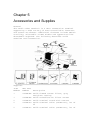
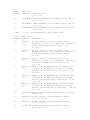
Chapter 5 - Accessories and Supplies
Appendix A - ANSI Definitions and Notation
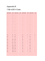
Appendix B - 7-Bit ASCII Code
Appendix C - Fill Character Requirements
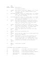
Figures
•
•
•
•
•
•
•
•
•
•
•
•
•
•
•
•
1-1
1-2
1-3
1-4
1-5
1-6
2-1
2-2
2-3
2-4
3-1
3-2
4-1
4-2
4-3
4-4
VT100 Terminal
VT100 Keyboard
VT100 Terminal (Rear View)
SET-UP A Mode Presentation
SET-UP B Mode Presentation
SET-UP B Mode Summary
VT100 Terminal Dimensions
VT100 Rear View
20 mA Current Loop Interface
Composite Video Output
Terminal Data Flow
VT100 Keyboard
VT100 Rear View
Advanced Video Option Installation
20 mA Current Loop Option
Terminal Controller Board
Tables
•
1-1 Categories of SET-UP Features
•
•
•
•
•
•
•
•
•
•
•
•
•
•
•
1-2 SET-UP Feature Change Summary
1-3 Nonfatal Displayed Error Codes
1-4 Problem Checklist
2-1 EIA RS-232-C Connector Signals
3-1 Machine States
3-2 Alphabetic Key Codes
3-3 Nonalphabetic Key Codes
3-4 Function Key Codes
3-5 Control Codes Generated
3-6 Cursor Control Key Codes
3-7 VT52 Mode Auxiliary Keypad Codes
3-8 ANSI Mode Auxiliary Keypad Codes
3-9 Special Graphics Characters
3-10 Control Characters
C-1 Fill Character Requirements
Chapter 1
Operator Information
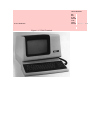
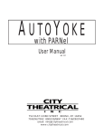
The VT100 is a simple device to operate. The terminal
(Figure 1-1) is basically a typewriter that uses a video
screen instead of paper and communicates with a computer.
If you can operate a typewriter, you can operate a VT100.
Chapter 1 is divided into five parts:
1. Controls and Indicators
2. Setup Mode
3. Definition of Each Setup Feature
4. Self-Testing the VT100
5. What to do in the Event of a Problem
Part 1 shows all the controls and indicators on the
terminal and summarizes the function of each, thus
providing a quick reference for these functions.
Part 2 defines the SET-UP mode and briefly summarizes its
features.
Part 3 describes each feature in detail. Refer to this
section if you need further information on a feature
mentioned in the SET-UP Summary provided in Part 2.
Part 4 provides information on self-testing the VT100. It
outlines the steps required to start the built-in selftests and how to interpret the results once the tests
have been run.
Part 5 provides a procedure to follow in case you
encounter any problem with the VT100. Easily recognized
failures with simple corrective actions are provided for
each symptom. Check the list on page 18 before calling
for service.
Part 1 -- Keyboard Control and Indicators
The VT100 terminal normally performs a two-part function.
It is an input device to a computer -- information
entered through the keyboard is sent to the computer. It
is simultaneously an output device for the computer -that is, data coming in from the computer is displayed on
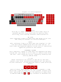
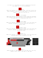
the video screen. The following controls and indicators
on the VT100 keyboard are illustrated in Figure 1-2.
SETUP
This key is used in conjunction with other keys to
perform specific functions such as setting tabs,
scrolling, and altering terminal characteristics.
ON LINE
This indicator lights to show that the VT100 is on-line
and ready to transmit or receive messages.
LOCAL
This indicator lights to show that the terminal is offline and cannot communicate with the host device. In
local mode the keyboard remains active and all characters
typed are placed on the screen.
KEYBOARD LOCKED
This indicator lights to show that the keyboard has been
turned off. The VT100 is still able to receive data from
the host. This condition can be cleared by entering and
exiting SET-UP mode.
L1--L4
These indicators are turned on and off by the host.
Consult your local operating procedures for the meaning
of each indicator. L1--L4 are also used to show self-test
errors.
Each of these keys causes the VT100 to transmit a code
which has a special meaning to your system. Consult your
local operating procedures for the meaning of these keys.
In SET-UP mode the and
keys increase or decrease the
brightness of the display. The and
keys move the
cursor left and right.
BACKSPACE
This key transmits a backspace code.
BREAK
This key transmits a break signal.
PF1 - PF4
Each of these keys causes the VT100 to transmit a code
which has a special meaning to your system. Consult your
local operating procedures for the meanings of these
keys.
Numeric Keypad
The numeric keypad enables numbers to be entered in
calculator fashion. Each key in the numeric keypad
generates the same character as the corresponding numeric
key on the main keyboard. The ENTER key corresponds to
the RETURN key. These keys may also be interpreted by the
host computer as special function keys. Consult your
local operating procedures for the meanings of these
keys.
DELETE
This key causes the VT100 to transmit a delete character
code to the host system. The deleted character may or may
not be erased from the screen.
RETURN
This key transmits either a carriage return (CR) code or
a carriage return (CR) and linefeed (LF) code. This is a
SET-UP selectable feature.
LINEFEED
This key transmits a linefeed code.
SHIFT
When pressed, this key enables the uppercase function of
all keys. If a key does not have an uppercase function
the SHIFT key will be disregarded.
RESET
When the terminal is in SET-UP mode, this key starts the
reset sequence. This has the same result as turning the
terminal power off and then on.
80/132 COLUMNS
When the terminal is in SET-UP A mode, this key switches
the display line size from 80 to 132 characters per line
or from 132 to 80 characters per line.
RECEIVE SPEED
When the terminal is in SET-UP B mode, this key steps the
terminal through the receive baud rate settings in
ascending order.
TRANSMIT SPEED
When the terminal is in SET-UP B mode, this key steps the
terminal through the transmit baud rate settings in
ascending order.
TOGGLE 1/0
When the terminal is in SET-UP B mode, this key turns the
selected operational feature on or off.
BELL G
When pressed in combination with the CTRL key, this key
causes a bell code to be sent to the host.
SET-UP A/B
When the terminal is in SET-UP mode, this key switches
the terminal from SET-UP A to SET-UP B or from SET-UP B
to SET-UP A.
LINE/LOCAL
In SET-UP mode, this key alternately places the VT100 ON
LINE or LOCAL to your system. When it is ON LINE, the
VT100 communicates with your system. When it is in LOCAL
the VT100 is electrically disconnected from your system.
CLEAR ALL TABS
In SET-UP A, this key clears all horizontal tabs set in
the VT100.
SET/CLEAR TAB
In SET-UP A, this key sets or clears individual
horizontal tabs.
CAPS LOCK
This key enables the transmission of uppercase alphabetic
characters only. All numeric and special symbol keys
remain in lowercase.
NO SCROLL
When first pressed, this key stops the transmission of
data from the computer to the VT100. When pressed a
second time, transmission resumes from where it was
stopped. Check your local operating procedures to ensure
that your system recognizes this key.
CTRL
When pressed in combination with another key, the CTRL
key causes the VT100 to transmit a code which has a
special meaning to your system.
TAB
This key transmits a tab code.
ESC
This key transmits a code which normally has a special
meaning to your system. In many applications, it tells
your system to treat the next keys pressed as a command.
Monitor Controls
The VT100 monitor contains only two controls: the power
switch and the power selector switch, which is used to
adapt the terminal to the available ac input voltage
range (see specifications).
Audible Indicators (Tones)
There are three audible alarms associated with the VT100:
a short tone (click), a long tone (bell), and a series of
long tones.
Short Tone (Click) -- The short tone is sounded by the
terminal whenever a key is pressed, with the following
exceptions:
•
•
•
SHIFT or CTRL keys do not generate any keyclick
because these keys do not transmit any codes but
only modify the codes transmitted by other keys.
KBD LOCKED indicator is turned on; in which case,
the characters typed are lost.
The keyclick feature has been turned off in SET-UP
mode.
Long Tone (Bell) -- The long tone is sounded by the
terminal to indicate one of the following conditions:
•
•
A bell code was received from the computer.
The cursor is eight characters away from the right
margin and the margin bell feature is enabled.
Series of Long Tones -- The terminal will sound the long
tone several times in rapid succession to indicate that
the nonvolatile memory (NVR) had difficulty in reading or
writing the SET-UP features. (When this occurs, check the
SET-UP features and then perform the Recall or Save
operation again.)
Part 2 -- Set-Up Mode
Unlike most terminals, the VT100 does not use switches or
jumpers to individually turn the built-in terminal
features on or off. Instead, the VT100 uses a nonvolatile
memory (NVR) which always remembers what features have
been selected, as if a switch had been set.
The selection and storage of built-in terminal features
is performed in a special mode of operation called SET-UP
mode. When you enter SET-UP mode, the status of the
features stored in the temporary memory is shown on the
screen. You can then change the features and store any
new feature selections either temporarily, by leaving
SET-UP mode; or on a fixed basis, by performing a Save
operation. In either case, the terminal operation will
reflect the new feature selection. If a recall operation
is performed, or the terminal is reset, or the terminal
power is turned OFF, all temporary feature settings are
replaced by the features that have been stored on a fixed
basis.
SET-UP Features at a Glance
When entered, SET-UP mode provides two brief summaries of
the current feature status. The first presentation -SET-UP A -- displays the location of the tab stops set in
the terminal and a visual ruler which numbers each
character position on the line. The second presentation - SET-UP B -- summarizes the status of the other terminal
features.
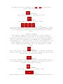
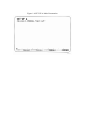
SET-UP A -- To enter SET-UP A, press the SET-UP key. The
display will now have a presentation similar to Figure 14. The bottom line of the display consists of a "ruler"
which numbers each character position available on a
line. The location of each tab stop is shown by a "T"
placed above the ruler. If the tab stop(s) set are those
desired, you may exit SET-UP mode by pressing the SET-UP
key again or you may now change the tabs to meet your
requirements.
SET-UP B -- SET-UP B mode may only be entered from SETUP A mode. To enter SET-UP B from SET-UP A, press the 5
key on the main keyboard. The display will then look like
Figure 1-5.
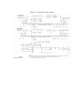
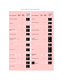
Figure 1-6 summarizes the SET-UP B presentation. This
summary allows you to quickly determine what features are
enabled. For additional information on a feature refer to
the Definition of Each Feature section.
To exit SET-UP B press the SET-UP key.
Determining What a SET-UP Feature Does
The SET-UP features are basically a series of options in
the VT100 that allow the terminal to be tailored to its
operating environment. Table 1-1 lists each feature and
places it in one or more of the following general
categories:
•
•
•
Installation
Computer compatibility
Operator comfort
The installation category concerns itself with the
initial installation of the terminal and any special
options that may be attached to the terminal. If any
terminal options are added or removed, or the physical
location of the installation is changed, verify the
settings of these SET-UP features.
Computer compatibility contains the features which must
be set correctly so that the VT100 can communicate with
the host computer. An error in these settings may cause
incorrect data to be sent to or received from the
computer; or an error may prevent the VT100 from
communicating with the computer. The settings for these
features must be obtained from the host computer
programmer, operator, or system manager since there are
many combinations of settings designed to work with
particular computers and special software. These feature
settings would normally change only when you need to
communicate with a different computer or a unique
software package.
The operator comfort category contains the SET-UP
features designed exclusively for the operator. These
features allow the operator to tailor the VT100 to fit
individual preference. These features do not affect any
operations that occur between the terminal and the
compuer.
The next section, Definition of Each SET-UP Feature,
describes the specific function of each feature.
How To Change a SET-UP Feature
Changing any or all of the SET-UP features is a simple
operation and is generally performed by following the
same basic steps.
1. Enter SET-UP mode by pressing the SET-UP key
2. Select the appropriate SET-UP mode by pressing the 5
key on the main keyboard each time you want to
switch from SET-UP A to SET-UP B or from SET-UP B to
SET-UP A.
3. Position the cursor above the feature switch or tab
stop to be changed. To position the cursor, the
SPACEBAR,
,
, TAB and RETURN keys may be used.
Some features do not use this step since a specific
key is dedicated to changing the feature.
4. Change the feature setting by pressing either the 6
key on the main keyboard or the appropriate
dedicated key. Each time the key is pressed the
feature will change, generally to the opposite
state.
Table 1-2 briefly summarizes the SET-UP features, the
SET-UP mode you must be in to change a given feature, and
the key used to change the feature setting.
Setting the Answerback Message
Setting the answerback message is different from setting
any of the other terminal features. An answerback message
can be typed into the VT100, using the following steps:
1. Place the terminal in SET-UP B mode.
2. Press the SHIFT and A key simultaneously. The
terminal will respond by placing A = on the screen.
(The SHIFT key is required. The CAPS LOCK key will
not work here.)
3. Type the message delimiter character which may be
any character not used in the actual answerback
mesage. The message delimiter character is not a
part of the answerback message. If a mistake is made
when typing the answerback message, type the message
delimiter character again and go back to step 2.
This is the only way to correct errors in the
answerback message.
4. Type the answerback message. The message may be up
to 20 characters, including space and control
characters. Control characters will be displayed as
a character to indicate their presence in the
message.
5. Type the message delimiter character. Once the
message delimiter character is typed the answerback
message will disappear from the screen.
Once the above steps have been completed the answerback
message will be temporarily stored in the VT100 and can
be saved with the Save operation.
Saving the SET-UP Features
SET-UP features may be changed and stored on either a
temporary or a fixed basis. To temporarily store a
feature, exit SET-UP mode after changing the feature; the
terminal now reacts according to the new setting. If a
recall operation is performed, or the terminal is reset,
or the terminal power is turned off, all temporary
feature settings are replaced by the features that have
been stored on a fixed basis.
To store SET-UP feature settings on a fixed basis,
perform a save operation. This is a simple operation that
is accomplished by performing the following steps:
1. Place the terminal in SET-UP mode.
2. Press the SHIFT and S keys simultaneously. The
screen will clear and the message "wait" will be
displayed in the upper-left corner. After a brief
wait, the terminal will return to SET-UP A mode.
NOTE: The save operation must be performed at the
terminal keyboard. The computer cannot perform this
operation, although it can temporarily modify the
settings of some VT100 features.
Once these steps have been performed, SET-UP features
which had been temporarily stored will now be stored on a
fixed basis.
Recalling SET-UP Features
The temporarily stored SET-UP feature settings may differ
from the settings which have been stored on a fixed
basis. If you wish to return to the fixed settings,
perform the recall operation as follows:
1. Place the terminal in SET-UP mode.
2. Press the SHIFT and R keys simultaneously. The
screen will clear and the message "wait" will appear
in the upper-left corner of the screen. After a
brief wait the terminal will return to SET-UP A
mode.
NOTE: When a recall operation is performed the contents
of the screen are destroyed.
Resetting the Terminal
The VT100 may be reset from the keyboard. When the
terminal is reset, the terminal memory is cleared and the
self-test program is run as if the terminal power switch
had been turned OFF and then back ON. To reset the
terminal:
1. Place the terminal in SET-UP mode.
2. Press the 0 key on the main keyboard. The VT100 will
be reset, the power on self-test will be run, and
the terminal will set according to the fixed SET-UP
features.
NOTE: When a reset operation is performed the contents of
the screen are destroyed and any options present may be
affected.
Part 3 -- Definition of Each SET-UP Feature
This section describes each SET-UP feature in detail (in
alphabetical order) and states how each feature affects
the terminal.
NOTE: Unless otherwise stated, entering SET-UP mode and
changing features does not result in the loss of data
displayed on the screen.
ANSI/VT52 Mode
The VT100 terminal follows two different programming
standards -- American National Standards Institute (ANSI)
and VT52. In ANSI mode, the VT100 will generate and
respond to coded sequences per ANSI standards X3.41-1974
and X3.64-1977. In VT52 mode, the VT100 terminal is
compatible with previous DIGITAL software using the VT52
video terminal. Both ANSI and VT52 modes are outlined in
the programmer's section of this manual.
ANSWERBACK Message
Answerback is a question and answer sequence where the
host computer asks the terminal to identify itself. The
VT100 answerback features provides the terminal with the
capability to identify itself by sending a message to the
host. The entire answerback sequence takes place
automatically without affecting the screen or requiring
operator action. The answerback message may also be
transmitted by typing CTRL-BREAK.
AUTO REPEAT
The auto repeat feature allows a key to be automatically
repeated at the rate of about 30 characters per second
when the key is held down for more than one-half second.
The auto repeat feature affects all keyboard keys except
the following:
•
•
SET-UP
ESC
•
•
•
•
NO SCROLL
TAB
RETURN
CTRL and any key
AUTO XON/XOFF
The VT100 is capable of automatically generating
synchronizing codes XON (DC1) and XOFF (DC3). The XOFF
code is used to stop the transmission of data from the
computer to the terminal; the XON code is used to resume
transmission. With the feature enabled, the VT100 will
generate the XOFF code when one of the following events
occur:
1. The internal buffer is nearly full
2. The NO SCROLL key is pressed
3. The terminal is placed in SET-UP mode
4. CTRL-S is pressed.
NOTE: The VT100 will always stop transmission when an
XOFF (DC3) code is received and will resume transmission
when an XON (DC1) code is received regardless of the AUTO
XON/XOFF feature setting.
When either the buffer empties, the NO SCROLL key is
pressed again, the terminal is taken out of SET-UP mode,
or CTRL-Q is pressed, the VT100 will transmit the XON
code to resume transmission from the computer to the
terminal.
If the host computer software does not support the
XON/XOFF codes, data sent during buffer full conditions,
or when the terminal is in SET-UP mode, may be lost.
BITS PER CHARACTER
This feature allows the terminal to transmit and receive
either 7- or 8-bit characters. When set for 8-bit
operation, bit 8 is set to a space (or 0) for characters
transmitted and is ignored for all characters received.
CHARACTERS PER LINE
The VT100 is capable of displaying either 80 or 132
characters per line. In the 80 character per line mode,
the screen is 80 characters wide by 24 lines high. In the
132 character per line mode, the screen is 132 characters
wide by 14 lines high (24 lines if the VT100 is equipped
with the Advanced Video Option). In the 132 character per
line mode, the displayed lines are physically the same
width as in the 80 character per line mode but the
characters are more compact.
NOTE: When changing from 80 to 132 character per line
mode or vice-versa, the current contents of the screen
are lost.
The use of double-width characters reduces the number of
characters per line by half.
CURSOR
The VT100 offers a choice of two cursor representations
to indicate the "active position", or where the next
character will be placed on the screen. The cursor may be
displayed as either a blinking underline (_) or a
blinking block ( ). The cursor selection may perform an
additional function; see the SGR escape sequence
definition in Chapter 3.
INTERLACE
This feature is used for high resolution options. To
reduce screen flicker the interlace feature should be
turned off if such an option is not installed.
KEYCLICK TONE
The keyclick is a tone which is generated every time a
code transmitting key is pressed. The keyclick may be
turned on or off to suit the operator's needs. However,
research and experience has shown that an operator is
more accurate when there is an audible feedback from the
keyboard.
Like the bell tone, the keyclick volume is not
adjustable.
LINE/LOCAL
The LINE/LOCAL feature allows the operator to easily
place the terminal in either an ON-LINE or a LOCAL (offline) condition. When the terminal is on-line (the
keyboard ON-LINE indicator is ON) all characters typed on
the keyboard are sent directly to the computer and
messages from the computer are displayed on the screen.
In the LOCAL condition (the keyboard LOCAL indicator is
ON), the terminal is electrically disconnected from the
computer; messages are not sent to or received from the
computer; and characters typed on the keyboard are echoed
on the screen directly.
MARGIN BELL
The margin bell feature is much the same as the bell in a
typewriter. If the cursor is eight characters from the
end of the current line while typing, the VT100 sounds a
tone to alert the operator.
NEW LINE
The new line feature enables the RETURN key on the
terminal to function like the RETURN key on an electric
typewriter. When the new line feature is enabled,
pressing the RETURN key generates the carriage return
(CR) and line feed (LF) codes. When a line feed code is
received, the code is interpreted as a carriage return
and line feed.
NOTE: If double line feeds occur consistently, turn this
feature off since the computer is already performing this
function automatically.
When the new line feature is disabled, the RETURN key
generates only the CR code; an LF code causes the
terminal to perform a line feed only.
PARITY
Parity, when enabled, checks for correct data
transmission. If a transmission error occurs, the VT100
can detect it and indicate its presence by placing a
checkerboard character ( ) on the screen in place of the
character with the error. The parity sense feature
determines if the parity is even or odd. When parity is
disabled, no parity bit is transmitted or received.
NOTE: If the parity feature is turned off, the parity
sense selection will be disregarded.
PARITY SENSE
The parity sense feature defines which of the two methods
of parity checking, odd or even, is being used by the
VT100. If the parity feature is on, the terminal's parity
sense must be matched to the parity the computer is
sending. If the parity sense features do not match, most
characters sent to the computer will be rejected even
though the character was received correctly by the VT100.
If a parity incompatibility occurs, the checkerboard
character ( ) will be shown on the screen in place of the
received character.
POWER
During the initial installation, the terminal display
must be set to the power line frequency. In the U.S. this
is set to 60 hertz.
RECEIVE SPEED
The receive speed must be set to match the computer
transmit speed. The VT100 is capable of receiving at any
one of the following preselected speeds: 50, 75, 110,
134.5, 150, 200, 300, 600, 1200, 1800, 2000, 2400, 3600,
4800, 9600, 19,200 baud.
SCREEN BACKGROUND
The screen background feature of the VT100 allows the
operator to determine the background of the screen. In
the normal screen mode, the display contains light
characters on a dark background; in the reverse screen
mode, the display contains dark characters on a light
background.
SCREEN BRIGHTNESS
Unlike most video terminals, the VT100 does not contain
switches or knobs to adjust screen brightness. Instead,
the VT100 electronically controls the screen brightness.
This feature eliminates the high failure rate of
mechanical controls and still allows the operator to
select the desired level of brightness for maximum
comfort under varied lighting conditions. This setting
may be saved like any other feature in the terminal.
SCROLL
Scrolling the upward or downward movement of existing
lines on the screen to make room for new lines at the
bottom or top of the screen. It can be performed in two
ways: jump scroll or smooth scroll. In jump scroll mode,
new lines appear on the screen as fast as the computer
sends them to the terminal. At the higher baud rates, the
data is very difficult to read due to the rapid movement
of the lines. In smooth scroll mode, a limit is placed on
the speed at which new lines of data may be sent to the
terminal. The movement of lines occurs at a smooth steady
rate allowing the data to be read as it appears on the
screen.
NOTE: Smooth scroll mode allows a maximum of six lines of
data per second to be added to the screen. The Auto
XON/XOFF feature must be enabled and supported by the
host computer to ensure that data is not lost when smooth
scroll mode is enabled.
TABS
Just like a typewriter, the VT100 can jump or tab to
preselected points on a line. These tab stops may be
individually changed, or totally cleared and then set.
TRANSMIT SPEED
Transmit speed must be set to match the computer receive
speed. The VT100 is capable of transmitting at any one of
the following preselected transmit speeds: 50, 75, 110,
134.5, 150, 200, 300, 600, 1200, 1800, 2000, 2400, 3600,
4800, 9600, and 19,200 baud.
Transmit speed is independent of receive speed; the
terminal may transmit data at one speed and receive data
at a different speed.
WRAPAROUND
When this feature is enabled, the 81st or 133rd character
(depending upon the line size selected) inserted on a
line is automatically placed in the first character
position of the next line. If the wraparound feature was
not enabled, the 81st or 133rd character and all
following characters would be overwritten into the last
character position of the current line.
NOTE: The use of double-width characters reduces the
number of characters per line by half.
(shifted)
The VT100 contains character sets for the U.S. and the
United Kingdom. The difference between the two character
sets is one character, the # or £ symbol. When the
standard U.S. character set is selected, the uppercase 3
key on the main keyboard displays the # character. The £
character is displayed when the U.K. character set is
selected.
Part 4 -- Self-Testing the VT100
A self-test mode is built into the VT100 that
automatically, or on command, tests the condition of the
terminal should a fault be suspected. The self-test
program checks the following items:
•
•
•
•
Advanced Video Memory (if option is installed)
Nonvolatile Memory (NVR)
Internal Memory
Keyboard
This test is performed automatically whenever the
terminal is turned on.
Self-Test Error Codes
There are two broad categories of errors: fatal and
nonfatal.
Fatal errors cause the terminal to immediately stop all
operations. No intelligible information is displayed on
the screen; however, the screen most likely contains a
random pattern of characters. The only error indication
(in addition to the random characters) is a possible
error code displayed on the programmable keyboard LEDs,
L1--L4; however, no terminal function, including the
lighting of LEDs, is guaranteed if a fatal error is
found.
NOTE: The loopback and EIA modem control tests are not
performed on power-up; they must be invoked separately
with the proper escape sequence. See the programmer's
section for further information on these tests.
Nonfatal errors do not halt the terminal processor.
Instead, the terminal is forced to LOCAL mode and an
error code character is displayed in the upper-left
corner of the screen.
There are five types of nonfatal errors:
1. (AVO) Advanced Video Option data RAM
2. (NVR) Nonvolatile data RAM checksum error
3. (KBD) Keyboard missing or malfunction
4. (Data) Data loopback error
5. (EIA) EIA modem control error
Table 1-3 shows the possible nonfatal error characters
that may appear on the screen and the failure represented
by each character.
Part 5 -- What To Do in the Event of a Problem
If it appears that there is a problem in the terminal,
you should initiate the power-up self-test program. This
test will help to determine if the problem lies in your
terminal or in some other part of the computer system.
Table 1-4 describes the items an operator can check prior
to making a service call.
Chapter 2
Installation, Interface Information and
Specifications
Installation
Site Considerations
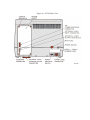
The design of the VT100 terminal (Figure 2-1) will
normally pose few constraints on selecting a place in
which to install the terminal. In most cases, any
environment suitable to the terminal operator will be a
satisfactory environment in which to operate the
terminal. Extremes of temperature and humidity should be
avoided. A summary of VT100 guaranteed operating
conditions is found at the end of this section.
Unpacking and Maintenance
The VT100 shipping carton contains the following items:
•
•
•
•
•
VT100
VT100
VT100
VT100
VT100
monitor
detached keyboard
power cord
SET-UP label
User's Guide
To install the VT100 perform the following steps:
1. Remove the VT100 from the shipping carton and place
it in the desired work area.
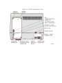
2. Place the keyboard in front of the terminal and plug
the keyboard coiled cord into the keyboard
receptacle located on the rear of the terminal
(Figure 2-2).
3. Verify that the power selector switch shows the
correct wall outlet voltage (115 V is standard in
the U.S.) and the power switch is off.
4. Connect the power cord to the power cord receptacle
on the rear of the terminal and plug the other end
of the power cord into a nearby wall outlet.
5. Connect the communications cable to the appropriate
communications receptacle.
6. Turn the power switch on. The terminal will now
automatically perform the power-up self-test and
either the ON LINE or LOCAL light located on the
keyboard will be turned on. After approximately one
minute the cursor will be visible in the upper-left
corner of the screen. If any other indication is
shown, refer to Part 5 of the operator information
chapter.
7. Set the desired SET-UP features as outlined in the
operator's section of this manual.
8. Once the installation setup procedure is complete,
record the SET-UP features selected on the VT100
SET-UP label and attach the label to the underside
of the keyboard.
User Maintenance
The keyboard keys are the only moving parts of the
terminal and require no preventive maintenance by the
owner. The VT100 surfaces may be cleaned with soap and
water or any mild detergent. Cleaners with solvents
should not be used.
The VT100 packaging is not meant to be weatherproof;
there are several openings in the case through which
liquids, coins, paper clips, and other objects can fall.
Such objects would disturb the electronic operation of
the terminal if they came into contact with the
circuitry. For this reason, avoid putting drinks and
metal objects on the top of the terminal, or using
excessive water to clean the terminal. Rubbing the keys
with a dry or barely moist cloth should suffice to clean
them. Do not remove the keycaps to clean them more
thoroughly; damage may result to the switch contacts if
they are replaced incorrectly.
Keep the ventilation slots clear. Blocking these slots by
placing objects on top of or under the VT100 may cause
the terminal to overheat.
Interface Information
EIA Interface
The basic VT100 operates on full duplex, asynchronous
communication lines. The terminal interfaces to the line
with a 25-pin connector mounted on the back of the
terminal which meets the requirements of EIA
specification RS-232-C. Table 2-1 summarizes the EIA
connector signals; the following paragraphs explain each
signal as used in the basic VT100.
Protective Ground -- Pin 1
This conductor is electrically bonded to the VT100
chassis. Use of this conductor for reference potential
purposes is not allowed.
Transmitted Data (from VT100) -- Pin 2
The VT100 transmits serially encoded characters and break
signals on this circuit, which is held in the mark state
when neither characters nor break signals are being
transmitted.
Received Data (to VT100) -- Pin 3
The VT100 receives serially encoded characters generated
by the user's equipment on this circuit.
Request to Send (from VT100) -- Pin 4
Asserted at all times when terminal is powered up.
Clear to Send (to VT100) -- Pin 5
Ignored at all times.
Data Set Ready (to VT100) -- Pin 6
Ignored at all times.
Signal Ground -- Pin 7
This conductor establishes the common ground reference
potential for all voltages on the interface. It is
permanently connected to the VT100 chassis.
Carrier Detect (to VT100) -- Pin 8
Ignored at all times.
Speed Select (from VT100) -- Pins 11, 19, and 23
This signal is alternately called Secondary Request to
Send. The basic VT100 maintains this line in the asserted
state at all times.
Speed Indicator (to VT100) -- Pin 12
This signal, alternately called Secondary Carrier Detect,
is ignored at all times.
Transmission Clock (to VT100) -- Pin 15
Ignored at all times.
Receive Clock (to VT100) -- Pin 17
Ignored at all times.
Data Terminal Ready (from VT100) -- Pin 20
Data Terminal Ready is asserted at all times except under
the following conditions:
1. Terminal is not powered up
2. Terminal is in LOCAL mode
3. The 3.5 second interval following the pressing of
SHIFT-BREAK.
Ring Indicator (to VT100) -- Pin 22
Ignored at all times.
Electrical Characteristics
VT100 Output Voltages -- On signals designated "from
VT100", the mark, or unasserted state, is -6.0 V to -
12.0 V; the space, or asserted state, is +6.0 V to
+12.0 V.
VT100 Input Voltages -- On signals designated "to VT100",
-25.0 V to +0.75 V or an open circuit is interpreted as a
mark or unasserted state, and +25.0 V to +2.25 V is
interpreted as a space or asserted state. Voltages
greater in magnitude than ±25 V are not allowed. These
levels are compatible with EIA STD RS-232-C and CCITT
Recommendation V.28.
Optional 20 mA Current Loop Interface
In most current loop applications, the VT100 will be
connected in a passive configuration -- that is, current
is supplied to the VT100. In this mode, the transmitter
and receiver are both passive, both optically isolated,
and the transmitter goes to the mark state when power is
turned off.
Conversion from active to passive (or vice versa)
requires moving a slide switch.
In active mode either the transmitter or the receiver or
both may be connected so that the VT100 sources the 20 mA
of current. In active mode isolation is not present and
the transmitter will go to the space state when power to
the VT100 is turned off.
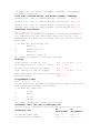
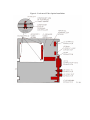
Figure 2-3 shows the 20 mA current loop interface
connector mounted to the access cover and the individual
pin assignment.
Electrical Characteristics
The electrical characteristics of the 20 mA current loop
interface are shown below:
Transmitter
Receiver
Min
Max
5.0 V 50 V
Min
--
Max
2.5 V
Open circuit
Voltage drop
voltage
marking
Voltage drop
-4.0 V Spacing current -3.0 mA
marking
Spacing current -2.0 mA Marking current 15 mA 50 mA
Marking current 20 mA 50 mA
In addition to the above specifications for passive
operation, active mode will place the transmitter or
receiver in series with a source of 17 V ±5 percent and
660 ohms.
External Video Connections
In addition to the EIA interface, the VT100 is also
capable of easily interfacing to external video devices.
The video devices may act either as a slave to the VT100
when connected to the composite video output or provide
synchronized video to the VT100 video section when
connected to the video input. The external video
connectors are the two female BNC connectors located on
the back of the terminal just below the EIA connector.
The upper connector, J8, is the video input while the
lower connector, J9, is the video output.
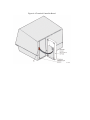
Composite Video Output (J9)
The composite video output provides RS170-like output
(see note) generated by combining the video signal with a
composite sync signal. This output contains all video
data appearing on the VT100 screen except that video
which comes from J8. The output has the following nominal
characteristics. (Refer to Figure 2-4).
1. Output impedance = 75 ohms, dc-coupled
2. Sync level = 0 V
3. Black level = approximately 0.3 V when loaded with
75 ohms
4. White level = approximately 1.0 V with a 75 ohm load
5. The composite sync waveform conforms to EIA RS170
standards. The vertical interval is composed of six
equalizing pulses, six vertical sync pulses, and six
more equalizing pulses. The timing is as follows:
Equalizing pulse
width
Vertical pulse width
Horizontal pulse
width
= 2.33µs ± 50ns
= 27.28µs ± 200ns
= 4.71µs ± 50ns
= 11.84µs ± 50ns/80 column
mode
Horizontal blank
width
= 12.34µs ± 50ns/132 column
mode
Front porch
= 1.54µs ± 50ns
NOTE: The use of dc-coupling is not in strict agreement
with RS170. To agree with RS170 the output load requires
a 10µF capacitor in series with the output. Failing to do
so, the 2 mA dc short circuit current requirement is
violated. This presents no problem with most monitors
which are in fact ac-coupled.
Video Input (J8)
An analog signal applied to the video input will be
"ORed" with the internal video signal in such a way that
the beam intensity at any point on the screen will
correspond to the intensity of that signal which would
tend to make the beam brighter at that point. A video
signal on this input affects only the internal screen and
does not appear on the composite video output. This input
has the following nominal characteristics.
1. Input impedance = 75 ohms, dc-coupled
2. Black level = 0 V
3. White level = 1.0 V
4. Maximum continuous input = ±2.0 V
The external video source must be synchronized to the
VT100; it may do this by referencing the composite sync
on the composite video output. This means that the VT100
video input will not synchronize with any composite video
source including the composite video output of another
VT100.
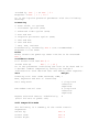
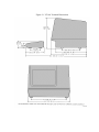
VT100 Specifications
Dimensions
Monitor
Keyboard
Height: 36.83 cm (14.5 inch)
Width: 45.72 cm (18 inch)
Depth: 36.20 cm (14.25 inch)
Height: 8.89 cm (3.5 inch)
Width: 45.72 cm (18 inch)
Depth: 20.32 cm (8 inch)
Minimum table depth: 51.4 cm (20.25 inch)
Weight
Monitor
Keyboard
Shipping Weight
13.6 kg (30 lbs)
2.0 kg (4.5 lbs)
18.6 kg (41 lbs)
Environment
Operating
Temperature: 10° to 40° C (50° to 104° F)
Relative humidity: 10% to 90%
Maximum wet bulb: 28° C (82° F)
Minimum dew point: 2° C (36° F)
Altitude: 2.4 km (8,000 ft)
Non-Operating Temperature: -40° to 66° C (-40° to 151° F)
Relative humidity: 0 to 95%
Altitude: 9.1 km (30,000 ft)
Power
Line Voltage
90-128 V RMS single phase, 2 wire
180-256 V RMS single phase, 2 wire
(switch-selectable)
Line Frequency 47-63 Hz
Current
2.2 A RMS maximum at 115 V RMS
1.1 A RMS maximum at 230 V RMS
Input Power
250 VA apparent 150 W maximum
Current
limiting
Power cord
3 A normal blow fuse
detachable, 3 prong, 1.9 m (6 ft)
Display
CRT
Format
12 inch diagonal measure, P4 phosphor
24 lines × 80 characters or 14 lines × 132
characters (selectable)
Character
Character
size
7 × 9 dot matrix with descenders
3.35 mm × 2.0 mm (0.132 inch × 0.078 inch)
in 80 column mode
3.35 mm × 1.3 mm (0.132 inch × 0.051 inch)
in 132 column mode
202 mm × 115 mm (8 inch × 4.5 inch)
Active
Display Size
Character Set 96 character displayable ASCII subset
(upper- and lowercase, numeric and
punctuation)
Cursor type
Keyboard-selectable, blinking block
character or blinking underline
Keyboard
General
83-key detachable unit with a 1.9 m (6 ft)
coiled cord attached
Key Layout
65-key arrangement and sculpturing similar
to standard typewriter keyboard with an 18key auxiliary keypad.
18-key numeric pad with period, comma,
minus, enter, and four general-purpose
function keys
Seven LEDs; three LEDs dedicated to ON LINE,
LOCAL and KBD LOCKED, four LEDs userprogrammable.
Key-click: sound simulates typewriter.
Bell:
Auxiliary
Keyboard
Visual
Indicators
Audible
Signals
1. sounds upon receipt of BEL code;
2. sounds eight characters from right
margin (keyboard-selectable)
Multiple bell: sounds upon detection of
error in SET-UP save or recall operation.
Communication
Type
Speeds
Code
Character
Format
Character Size
EIA
Full duplex: 50, 75, 110 (two stop bits),
134.5, 150, 200, 300, 600, 1200, 1800,
2000, 2400, 3600, 4800, 9600, 19,200
ASCII
Asynchronous
7 or 8 bits; keyboard-selectable. (Note:
if 8-bit character is selected, eighth
bits is always space).
Parity
Even, odd, or none -- keyboard-selectable
Synchronization Keyboard-selectable via automatic
generation of XON and XOFF control codes.
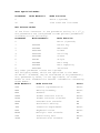
How to Order Hardware Documentation
The following VT100 Video Terminal hardware manuals can
be purchased from DIGITAL's Accessory and Supplies Group.
Part No.
Title
EK-VT100-UG VT100 User Guide
EK-VT100-J1 VT100 Mini Maintenance Manual
EK-VT100-TM VT100 Technical Manual
EK-VT100-IP VT100 Illustrated Parts Breakdown (IPB)
MP-00633
VT100 Print Set
All purchase orders for hardware manuals should be
forwarded to:
Digital Equipment Corporation
Cotton Road
Nashua, N.H. 03060
Supplies and Accessories Group (P086)
Purchase orders must show shipping and billing addresses
and state whether a partial shipment will be accepted.
All correspondence and invoicing inquiries should be
directed to the above address.
Chapter 3
Programmer Information
The VT100 terminal normally performs a two-part function.
It is an input device to a computer -- information
entered through the keyboard is sent to the computer. It
is simultaneously an output device for the computer -that is, data coming in from the computer is displayed on
the video screen. Figure 3-1 shows the data flow.
This section of the user's manual discusses data flow
between the VT100 and the host. Included are codes
generated by the keyboard; the transmission protocol
followed by the terminal; and the actions and reactions
of the terminal to control functions in both ANSI and
VT52 modes of operation.
The Keyboard
The VT100 uses a keyboard with a key arrangement similar
to an ordinary office typewriter, as shown in Figure 3-2.
In addition to the standard typewriter keys the VT100
keyboard has additional keys and indicators used to
generate control sequences, cursor control commands, and
to show the current terminal status.
LED Indicators
The keyboard has seven light emitting diodes (LEDs) of
which two are committed to the complementary ONLINE/LOCAL function. The power on condition is implicitly
shown by one of the two LEDs being on; that is, if the
keyboard is connected and power is on, one of these LEDs
will be on.
A third LED indicates a "keyboard locked" condition. In
this condition the keyboard has been "turned off"
automatically by the terminal due to a full buffer or by
the host through the transmission of an XOFF to the
terminal.
The four remaining LEDs are programmable and can be
assigned any meaning for specific applications. The code
sequences to turn these LEDs on or off are discussed
later in this chapter.
SET-UP
The SET-UP key is at the upper-left corner of the main
key array. Operations performed in SET-UP mode can be
stored in nonvolatile memory (NVR) so that turning the
terminal power off does not, by itself, alter the
terminal configuration.
The procedures to change the SET-UP features are provided
in the operator's information section of this manual.
Those SET-UP features which may be modified by the host
are listed in Table 3-1 and described in detail under the
escape sequences.
Keyboard Operation
The operator uses the keyboard to transmit codes to the
host. Some keys transmit one or more codes to the host
immediately when typed. Other keys such as CTRL and SHIFT
do not transmit codes when typed, but modify the codes
transmitted by other keys. The code-transmitting keys
cause the terminal to make a clicking sound to verify to
the operator that the keystroke has been processed by the
terminal. If two code-transmitting keys are pressed
together, two codes will be transmitted according to the
order in which the keys were typed. The terminal will not
wait for the keys to be lifted, but will transmit both
codes as soon as possible after the keys are first typed.
If three such keys are pressed simultaneously, the codes
for the first two keys are transmitted immediately; the
code for the third will be transmitted when one of the
first two keys is lifted.
Alphabetic Keys -- The VT100 will transmit the lowercase
code unless either or both of the SHIFT keys are down, or
unless the CAPS LOCK key is down. Pressing the CAPS LOCK
key will lock only the 26 alphabetic keys in the shifted
(uppercase) mode. Table 3-2 shows the codes generated by
the alphabetic keys.
Nonalphabetic Keys -- Each of the nonalphabetic keys can
be used to generate two different codes. One code will be
generated if neither SHIFT key is pressed. The other code
will be generated if either or both of the SHIFT keys are
down. Unlike the SHIFT LOCK key of a typewriter, the CAPS
LOCK key does not affect these keys; it affects only the
alphabetic keys. Table 3-3 shows the nonalphabetic keys
and the codes they generate.
Function Keys -- There are several keys on the keyboard
which transmit control codes. Control codes do not
produce displayable characters but are codes for
functions. If these codes are received by the terminal,
the VT100 will perform the associated function as shown
in Table 3-4.
NO SCROLL -- When the NO SCROLL key is pressed it
generates a single XOFF code, inhibits further scrolling
and freezes the screen. When pressed again the same key
generates XON. In practice, if the software recognizes
XOFF, the host will stop transmitting until the NO SCROLL
key is pressed again to allow scrolling. If the XOFF/XON
feature is disabled (SET-UP function) the NO SCROLL key
causes no action.
BREAK -- Typing the BREAK key causes the transmission
line to be forced to its zero state for 0.2333 seconds ±
10 percent. If either SHIFT key is down, the time is
increased to 3.5 seconds ± 10 percent. Data Terminal
Ready is also deasserted during this interval. At the
conclusion of the 3.5 second interval Data Terminal Ready
will again be asserted.
The SHIFT and BREAK keys typed together provide the longbreak-disconnect function. Used with properly configured
modems with RS-232-C levels, it will cause both the local
and remote data sets to disconnect. For modems that are
connected via the 20 mA current loop, issuing the long
space may disconnect the remote data set only.
The CTRL and BREAK keys typed together cause the
transmission of the answerback message.
The BREAK key does not function when the VT100 is in
LOCAL mode.
Auto Repeating -- All keys will auto repeat except: SETUP, ESC, NO SCROLL, TAB, RETURN, and any key pressed with
CTRL. Auto repeating works as follows: when a key is
typed, its code(s) is sent once, immediately. If the key
is held down for more than ½ second, the code(s) will be
sent repeatedly at a rate of approximately 30 Hz (less if
low transmit baud rates are used) until the key is
released.
CTRL (Control) -- The CTRL key is used in conjunction
with other keys on the keyboard to generate control
codes. If the CTRL key is held down when any of the keys
in Table 3-5 are typed, the code actually transmitted is
in the range 0008-0378.
Cursor Control -- The keyboard also contains four keys
labeled with arrows in each of four directions. These
keys transmit control sequences. If the host echoes these
control sequences back to the terminal, the cursor will
move one character up, down, right, or left. Table 3-6
shows the control sequences generated by each key.
Auxiliary Keypad -- The keys on the auxiliary keypad
normally transmit the codes for the numerals, decimal
point, minus sign, and comma. In addition, the key
labeled ENTER transmits the same code as the RETURN key.
The host cannot tell if these keys were typed on the
auxiliary keypad as opposed to the corresponding keys on
the main keyboard. Therefore, software which requires
considerable numeric data entry need not be rewritten to
use the keypad.
However, if software must be able to distinguish between
pressing a key on the auxiliary keypad and pressing the
corresponding key on the main keyboard, the host can give
the terminal a command to place it in keypad application
mode. In keypad application mode all keys on the
auxiliary keypad are defined to give control sequences
which may be used by the host as user-defined functions.
The codes sent by the auxiliary keypad for the four
combinations of the VT52/ANSI mode and keypad
numeric/application mode are shown in Tables 3-7 and 3-8.
None of the keys are affected by pressing the SHIFT, CAPS
LOCK, or CTRL keys.
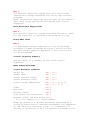
Special Graphics Characters
If the Special Graphics set is selected, the graphics for
ASCII codes 1378 through 1768 will be replaced according
to Table 3-9. (See the SCS control sequence).
Communications Protocols
Full Duplex
The terminal can operate at transmission speeds up to
19,200 baud. However, the terminal may not be able to
keep up with incoming data. The terminal stores incoming
characters in a 64-character buffer and processes them on
a first-in/first-out basis. When the content of the
buffer reaches 32 characters, the terminal will transmit
0238 (XOFF or DC3). On this signal the host should suspend
its transmission to the terminal. Eventually, if the host
stops transmitting, the terminal will deplete the buffer.
When 16 characters remain in the buffer the terminal will
transmit 021 8 (XON or DC1) to signal the host that it may
resume transmission.
If the host fails to respond to an XOFF from the terminal
in a timely manner, the buffer will continue to fill.
When the 64-character capacity of the buffer is exceeded,
a condition occurs called "buffer overflow". To determine
if the buffer will overflow use the following formulas:
No. of characters to overflow = 32 - [3 ×
(receiver speed /
transmit speed) ]
Time to respond to XOFF
= No. of characters to
overflow ×
(bits per character +
parity bit + 2) /
receiver speed
Example 1:
The VT100 is transmitting 8-bit characters with no parity
at 1200 baud and receiving at 1200 baud. The terminal has
just sent an XOFF which the host must respond to with
0.2416 second to avoid a buffer overflow.
No. of characters to overflow = 32 - [3 × (1200 /
1200) ] = 29 characters
Time to respond to XOFF
= 29 × [8 + 0 + 2) / 1200 =
0.2416 second
Example 2:
The VT100 is transmitting 7-bit characters with parity at
300 baud and receiving at 1200 baud. The terminal has
just sent an XOFF which the host must respond to within
0.1666 second to avoid a buffer overflow.
No. of characters to overflow = 32 - [3 × (1200 / 300) ] =
20 characters
Time to respond to XOFF
= 20 × [7 + 1 + 2) / 1200 =
0.1666 second
If the buffer overflows, the VT100 will begin to discard
incoming characters and the error character will be
displayed.
Software which does not support receipt of the XOFF/XON
signals from the terminal can still use the VT100
provided the software never sends the ESC code to the
terminal, the baud rate is limited to 4800 or less, and
the software does not use smooth scrolling or split
screen features.
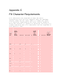
Alternatively, if XOFF/XON cannot be used, fill
characters may be used after characters or character
strings are sent to the VT100. A reference chart of fill
characters required for these functions is included in
Appendix C.
Two of the terminal functions, Reset and Self-Test,
reinitialize the terminal and erase the buffer. This
means that if characters are received subsequent to the
commands to perform these two functions and the
characters are placed in the buffer, the character would
be destroyed without being processed.
To compensate for this, the host may act in one of two
ways:
1. Immediately after sending the terminal the commands
to perform either the Reset or Self-Test functions,
the host may act as if it had received XOFF from the
terminal, thus sending no more characters until it
receives XON. The terminal will transmit XON only
after it completes the specified operation and the
XOFF/XON feature is enabled.
2. When the first method cannot be implemented, a delay
of no less than 10 seconds may be used to allow the
terminal time to complete the invoked function. This
method, however, does not guarantee against the loss
of data when an invoked function has detected an
error; and while this delay is currently adequate,
future options may require a change in the time
delay.
The XOFF/XON synchronization scheme has an advantage over
requiring the host to insert delays or filler characters
in its data stream. Requiring a minimum of software
support, XON/XOFF ensures that every character or command
sent to the VT100 will be processed in correct order. It
frees interface programs from all timing considerations
and results in more reliable operation.
In addition to the buffer-filling condition, there are
two other means of transmitting XOFF and XON; the NO
SCROLL key, and Control S/Control Q. If the XON/XOFF
feature is enabled, the VT100 will coordinate these three
sources of XOFF and XON so that the desired effect
occurs. For example, if the buffer-filling condition has
caused an XOFF to be sent, and then the operator types
the NO SCROLL key, a second XOFF is not sent. Instead of
sending an XON when the buffer empties, the VT100 waits
until the operator types the NO SCROLL key again before
sending XON.
Also, entering SET-UP mode causes the VT100 to
temporarily stop taking characters from the buffer. An
XOFF will be sent if the buffer becomes nearly full.
Use of Control S and Control Q will also be synchronized
with the NO SCROLL key.
If the XON/XOFF feature is disabled, the buffer-filling
condition will not send an XOFF, the NO SCROLL key is
disabled, and Control S and Control Q will be transmitted
as typed.
The VT100 also recognizes received XOFF and XON. Receipt
of XOFF will inhibit the VT100 from transmitting any
codes except XOFF and XON. From three to seven keystrokes
on the keyboard will be stored in a keyboard buffer (some
keys transmit two or three codes, e.g., cursor controls).
If the keyboard buffer overflows, keyclicks will stop and
the KBD LOCKED LED will come on. Transmission resumes
upon receipt of XON.
If the user transmits an XOFF to the host (by Control S
or NO SCROLL), the host should not echo any further typein until the user types XON. This places the burden of
not overloading the host's output buffer on the user.
Entering and exiting SET-UP clears the keyboard locked
condition.
Terminal Control Commands
The VT100 has many control commands which cause it to
take action other than displaying a character on the
screen. In this way, the host can command the terminal to
move the cursor, change modes, ring the bell, etc. The
following paragraphs discuss the terminal control
commands.
Control Characters
Control characters have values of 000 8 - 037 8, and 177 8.
The control characters recognized by the VT100 are shown
in Table 3-10. All other control codes cause no action to
be taken.
Control characters (codes 0 8 to 37 8 inclusive) are
specifically excluded from the control sequence syntax,
but may be embedded within a control sequence. Embedded
control characters are executed as soon as they are
encountered by the VT100. The processing of the control
sequence then continues with the next character received.
The exceptions are: if the character ESC occurs, the
current control sequence is aborted, and a new one
commences beginning with the ESC just received. If the
character CAN (308) or the character SUB (32 8) occurs, the
current control sequence is aborted. The ability to embed
control characters allows the synchronization characters
XON and XOFF to be interpreted properly without affecting
the control sequence.
Control Sequences
The VT100 is an upward and downward software compatible
terminal; that is, previous DIGITAL video terminals have
DIGITAL private standards for control sequences. The
American National Standards Institute (ANSI) has since
standardized escape and control sequences in terminals in
documents X3.41-1974 and X3.64-1977.
NOTE: The ANSI standards allow the manufacturer
flexibility in implementing each function. This manual
describes how the VT100 will respond to the implemented
ANSI control function.
The VT100 is compatible with both the previous DIGITAL
standard and ANSI standards. Customers may use existing
DIGITAL software designed around the VT52 or new VT100
software. The VT100 has a "VT52 compatible" mode in which
the VT100 responds to control sequences like a VT52. In
this mode, most of the new VT100 features cannot be used.
Throughout this section of the manual, references will be
made to "VT52 mode" or "ANSI mode". These two terms are
used to indicate the VT100's software compatibility. All
new software should be designed around the VT100 "ANSI
mode". Future DIGITAL video terminals will not
necessarily be committed to VT52 compatibility.
NOTE: ANSI standards may be obtained by writing:
Sales Department
American National Standards Institute
1430 Broadway
New York, New York 10018
Valid ANSI Mode Control Sequences
Definitions
The following listing defines the basic elements of the
ANSI mode control sequences. A more complete listing
appears in Appendix A.
Control Sequence Introducer (CSI)
An escape sequence that provides supplementary
controls and is itself a prefix affecting the
interpretation of a limited number of contiguous
characters. In the VT100 the CSI is ESC [.
Parameter
1. A string of zero or more decimal characters
which represent a single value. Leading zeroes
are ignored. The decimal characters have a
range of 0 (60 8) to 9 (718).
2. The value so represented.
Numeric Parameter
A parameter that represents a number, designated by
Pn.
Selective Parameter
A parameter that selects a subfunction from a
specified list of subfunctions, designated by Ps. In
general, a control sequence with more than one
selective parameter causes the same effect as
several control sequences, each with one selective
parameter, e.g., CSI Psa; Psb; Psc F is identical to
CSI Psa F CSI Psb F CSI Psc F.
Parameter String
A string of parameters separated by a semicolon
(738).
Default
A function-dependent value that is assumed when no
explicit value, or a value of 0, is specified.
Final character
A character whose bit combination terminates an
escape or control sequence.
Examples:
1. Control sequence for double-width line (DECDWL) ESC
# 6
Sequence
Octal Representation of
Sequence
Sequence
Octal Representation of
Sequence
2. Control sequence to turn off all character
attributes, and then turn on underscore and blink
attributes (SGR). ESC [ 0 ; 4 ; 5 m
Sequence
Octal Representation of Sequence
Alternative sequences which will accomplish the same
thing:
Sequence
Octal Representation of Sequence
a. ESC [
b. ESC [
ESC [
ESC [
c. ESC [
m
;
m
4
5
0
4 ; 5 m
033
033
m
033
m
033
; 04; 005 033
065
133
133
133
133
133
155
073
155
064
065
060
064 073 065 155
155
155
073 060 064 073 060 060
Control Sequences
All of the following escape and control sequences are
transmitted from the host computer to the VT100 unless
otherwise noted. All of the control sequences are a
subset of those specified in ANSI X3.64-1977 and ANSI
X3.41-1974.
CPR -- Cursor Position Report -- VT100 to Host
ESC [ Pn ; Pn R
default value: 1
The CPR sequence reports the active position by means of
the parameters. This sequence has two parameter values,
the first specifying the line and the second specifying
the column. The default condition with no parameters
present, or parameters of 0, is equivalent to a cursor at
home position.
The numbering of lines depends on the state of the Origin
Mode (DECOM).
This control sequence is solicited by a device status
report (DSR) sent from the host.
CUB -- Cursor Backward -- Host to VT100 and VT100 to Host
ESC [ Pn D
default value: 1
The CUB sequence moves the active position to the left.
The distance moved is determined by the parameter. If the
parameter value is zero or one, the active position is
moved one position to the left. If the parameter value is
n, the active position is moved n positions to the left.
If an attempt is made to move the cursor to the left of
the left margin, the cursor stops at the left margin.
Editor Function
CUD -- Cursor Down -- Host to VT100 and VT100 to Host
ESC [ Pn B
default value: 1
The CUD sequence moves the active position downward
without altering the column position. The number of lines
moved is determined by the parameter. If the parameter
value is zero or one, the active position is moved one
line downward. If the parameter value is n, the active
position is moved n lines downward. In an attempt is made
to move the cursor below the bottom margin, the cursor
stops at the bottom margin. Editor Function
CUF -- Cursor Forward -- Host to VT100 and VT100 to Host
ESC [ Pn C
default value: 1
The CUF sequence moves the active position to the right.
The distance moved is determined by the parameter. A
parameter value of zero or one moves the active position
one position to the right. A parameter value of n moves
the active position n positions to the right. If an
attempt is made to move the cursor to the right of the
right margin, the cursor stops at the right margin.
Editor Function
CUP -- Cursor Position
ESC [ Pn ; Pn H
default value: 1
The CUP sequence moves the active position to the
position specified by the parameters. This sequence has
two parameter values, the first specifying the line
position and the second specifying the column position. A
parameter value of zero or one for the first or second
parameter moves the active position to the first line or
column in the display, respectively. The default
condition with no parameters present is equivalent to a
cursor to home action. In the VT100, this control behaves
identically with its format effector counterpart, HVP.
Editor Function
The numbering of lines depends on the state of the Origin
Mode (DECOM).
CUU -- Cursor Up -- Host to VT100 and VT100 to Host
ESC [ Pn A
default value: 1
Moves the active position upward without altering the
column position. The number of lines moved is determined
by the parameter. A parameter value of zero or one moves
the active position one line upward. A parameter value of
n moves the active position n lines upward. If an attempt
is made to move the cursor above the top margin, the
cursor stops at the top margin. Editor Function
DA -- Device Attributes
ESC [ Pn c
default value: 0
1. The host requests the VT100 to send a device
attributes (DA) control sequence to identify itself
by sending the DA control sequence with either no
parameter or a parameter of 0.
2. Response to the request described above (VT100 to
host) is generated by the VT100 as a DA control
sequence with the numeric parameters as follows:
Option Present
Sequence Sent
No options
Processor option (STP)
Advanced video option (AVO)
ESC [?1;0c
ESC [?1;1c
ESC [?1;2c
AVO and STP
Graphics option (GPO)
GPO and STP
GPO and AVO
ESC
ESC
ESC
ESC
[?1;3c
[?1;4c
[?1;5c
[?1;6c
Option Present
Sequence Sent
GPO, STP and AVO
ESC [?1;7c
DECALN -- Screen Alignment Display (DEC Private)
ESC # 8
This command fills the entire screen area with uppercase
Es for screen focus and alignment. This command is used
by DEC manufacturing and Field Service personnel.
DECANM -- ANSI/VT52 Mode (DEC Private)
This is a private parameter applicable to set mode (SM)
and reset mode (RM) control sequences. The reset state
causes only VT52 compatible escape sequences to be
interpreted and executed. The set state causes only ANSI
"compatible" escape and control sequences to be
interpreted and executed.
DECARM -- Auto Repeat Mode (DEC Private)
This is a private parameter applicable to set mode (SM)
and reset mode (RM) control sequences. The reset state
causes no keyboard keys to auto-repeat. The set state
causes certain keyboard keys to auto-repeat.
DECAWM -- Autowrap Mode (DEC Private)
This is a private parameter applicable to set mode (SM)
and reset mode (RM) control sequences. The reset state
causes any displayable characters received when the
cursor is at the right margin to replace any previous
characters there. The set state causes these characters
to advance to the start of the next line, doing a scroll
up if required and permitted.
DECCKM -- Cursor Keys Mode (DEC Private)
This is a private parameter applicable to set mode (SM)
and reset mode (RM) control sequences. This mode is only
effective when the terminal is in keypad application mode
(see DECKPAM) and the ANSI/VT52 mode (DECANM) is set (see
DECANM). Under these conditions, if the cursor key mode
is reset, the four cursor function keys will send ANSI
cursor control commands. If cursor key mode is set, the
four cursor function keys will send application
functions.
DECCOLM -- Column Mode (DEC Private)
This is a private parameter applicable to set mode (SM)
and reset mode (RM) control sequences. The reset state
causes a maximum of 80 columns on the screen. The set
state causes a maximum of 132 columns on the screen.
DECDHL -- Double Height Line (DEC Private)
Top Half: ESC # 3
Bottom Half: ESC # 4
These sequences cause the line containing the active
position to become the top or bottom half of a doubleheight double-width line. The sequences must be used in
pairs on adjacent lines and the same character output
must be sent to both lines to form full double-height
characters. If the line was single-width single-height,
all characters to the right of the center of the screen
are lost. The cursor remains over the same character
position unless it would be to the right of the right
margin, in which case it is moved to the right margin.
NOTE: The use of double-width characters reduces the
number of characters per line by half.
DECDWL -- Double-Width Line (DEC Private)
ESC # 6
This causes the line that contains the active position to
become double-width single-height. If the line was
single-width single-height, all characters to the right
of the screen are lost. The cursor remains over the same
character position unless it would be to the right of the
right margin, in which case, it is moved to the right
margin.
NOTE: The use of double-width characters reduces the
number of characters per line by half.
DECID -- Identify Terminal (DEC Private)
ESC Z
This sequence causes the same response as the ANSI device
attributes (DA). This sequence will not be supported in
future DEC terminals, therefore, DA should be used by any
new software.
DECINLM -- Interlace Mode (DEC Private)
This is a private parameter applicable to set mode (SM)
and reset mode (RM) control sequences. The reset state
(non-interlace) causes the video processor to display 240
scan lines per frame. The set state (interlace) causes
the video processor to display 480 scan lines per frame.
There is no increase in character resolution.
DECKPAM -- Keypad Application Mode (DEC Private)
ESC =
The auxiliary keypad keys will transmit control sequences
as defined in Tables 3-7 and 3-8.
DECKPNM -- Keypad Numeric Mode (DEC Private)
ESC >
The auxiliary keypad keys will send ASCII codes
corresponding to the characters engraved on the keys.
DECLL -- Load LEDS (DEC Private)
ESC [ Ps q
default value: 0
Load the four programmable LEDs on the keyboard according
to the parameter(s).
Parameter
Parameter Meaning
0
1
2
3
4
LED numbers are
Clear LEDs L1 through L4
Light L1
Light L2
Light L3
Light L4
indicated on the keyboard.
DECOM -- Origin Mode (DEC Private)
This is a private parameter applicable to set mode (SM)
and reset mode (RM) control sequences. The reset state
causes the origin to be at the upper-left character
position on the screen. Line and column numbers are,
therefore, independent of current margin settings. The
cursor may be positioned outside the margins with a
cursor position (CUP) or horizontal and vertical position
(HVP) control.
The set state causes the origin to be at the upper-left
character position within the margins. Line and column
numbers are therefore relative to the current margin
settings. The cursor is not allowed to be positioned
outside the margins.
The cursor is moved to the new home position when this
mode is set or reset.
Lines and columns are numbered consecutively, with the
origin being line 1, column 1.
DECRC -- Restore Cursor (DEC Private)
ESC 8
This sequence causes the previously saved cursor
position, graphic rendition, and character set to be
restored.
DECREPTPARM -- Report Terminal Parameters
ESC [ <sol>; <par>; <nbits>; <xspeed>; <rspeed>;
<clkmul>; <flags> x
These sequence parameters are explained below in the
DECREQTPARM sequence.
DECREQTPARM -- Request Terminal Parameters
ESC [ <sol> x
The sequence DECREPTPARM is sent by the terminal
controller to notify the host of the status of selected
terminal parameters. The status sequence may be sent when
requested by the host or at the terminal's discretion.
DECREPTPARM is sent upon receipt of a DECREQTPARM. On
power-up or reset, the VT100 is inhibited from sending
unsolicited reports.
The meanings of the sequence parameters are:
Parameter Value Meaning
<sol>
<par>
<nbits>
<xspeed>,
<rspeed>
0 or
none
This message is a request (DECREQTPARM)
and the terminal will be allowed to send
unsolicited reports. (Unsolicited
reports are sent when the terminal exits
the SET-UP mode).
1
This message is a request; from now on
the terminal may only report in response
to a request.
2
This message is a report (DECREPTPARM).
3
This message is a report and the
terminal is only reporting on request.
1
No parity set
4
Parity is set and odd
5
Parity is set and even
1
8 bits per character
2
7 bits per character
0
50
8
75
Bits per second
Parameter
Value Meaning
16
110
24
134.5
32
150
40
200
48
300
56
600
64
1200
72
1800
80
2000
88
2400
96
3600
104
4800
112
9600
120
19200
<clkmul>
1
The bit rate multiplier is 16.
<flags>
0-15
This value communicates the four switch
values in block 5 of SET UP B, which are
only visible to the user when an STP
option is installed. These bits may be
assigned for an STP device. The four
bits are a decimal-encoded binary
number.
DECSC -- Save Cursor (DEC Private)
ESC 7
This sequence causes the cursor position, graphic
rendition, and character set to be saved. (See DECRC).
DECSCLM -- Scrolling Mode (DEC Private)
This is a private parameter applicable to set mode (SM)
and reset mode (RM) control sequences. The reset state
causes scrolls to "jump" instantaneously. The set state
causes scrolls to be "smooth" at a maximum rate of six
lines per second.
DECSCNM -- Screen Mode (DEC Private)
This is a private parameter applicable to set mode (SM)
and reset mode (RM) control sequences. The reset state
causes the screen to be black with white characters. The
set state causes the screen to be white with black
characters.
DECSTBM -- Set Top and Bottom Margins (DEC Private)
ESC [ Pn; Pn r
default values: see below
This sequence sets the top and bottom margins to define
the scrolling region. The first parameter is the line
number of the first line in the scrolling region; the
second parameter is the line number of the bottom line in
the scrolling region. Default is the entire screen (no
margins). The minimum size of the scrolling region
allowed is two lines, i.e., the top margin must be less
than the bottom margin. The cursor is placed in the home
position (see Origin Mode DECOM).
DECSWL -- Single-width Line (DEC Private)
ESC # 5
This causes the line which contains the active position
to become single-width single-height. The cursor remains
on the same character position. This is the default
condition for all new lines on the screen.
DECTST -- Invoke Confidence Test
ESC [ 2 ; Ps y
Ps is the parameter indicating the test to be done. Ps is
computed by taking the weight indicated for each desired
test and adding them together. If Ps is 0, no test is
performed but the VT100 is reset.
Test
Weight
Power up self-test (ROM check sum,
RAM, NVR keyboard and AVO if
installed)
Data Loop Back
EIA modem control test
Repeat Selected Test(s)
indefinitely (until failure or power
off)
DSR -- Device Status Report
1
2 (loop back
connector
required)
4 (loop back
connector
required)
8
ESC [ Ps n
default value: 0
Requests and reports the general status of the VT100
according to the following parameter(s).
Parameter Parameter Meaning
0
Response from VT100 -- Ready, No malfunctions
detected (default)
3
Response from VT100 -- Malfunction -- retry
5
Command from host -- Please report status (using
a DSR control sequence)
6
Command from host -- Please report active
position (using a CPR control sequence)
DSR with a parameter value of 0 or 3 is always sent as a
response to a requesting DSR with a parameter value of 5.
ED -- Erase In Display
ESC [ Ps J
default value: 0
This sequence erases some or all of the characters in the
display according to the parameter. Any complete line
erased by this sequence will return that line to single
width mode. Editor Function
Parameter Parameter Meaning
0
1
2
Erase from the active position to the end of the
screen, inclusive (default)
Erase from start of the screen to the active
position, inclusive
Erase all of the display -- all lines are
erased, changed to single-width, and the cursor
does not move.
EL -- Erase In Line
ESC [ Ps K
default value: 0
Erases some or all characters in the active line
according to the parameter. Editor Function
Parameter Parameter Meaning
0
1
2
Erase from the active position to the end of the
line, inclusive (default)
Erase from the start of the screen to the active
position, inclusive
Erase all of the line, inclusive
HTS -- Horizontal Tabulation Set
ESC H
Set one horizontal stop at the active position. Format
Effector
HVP -- Horizontal and Vertical Position
ESC [ Pn ; Pn f
default value: 1
Moves the active position to the position specified by
the parameters. This sequence has two parameter values,
the first specifying the line position and the second
specifying the column. A parameter value of either zero
or one causes the active position to move to the first
line or column in the display, respectively. The default
condition with no parameters present moves the active
position to the home position. In the VT100, this control
behaves identically with its editor function counterpart,
CUP. The numbering of lines and columns depends on the
reset or set state of the origin mode (DECOM). Format
Effector
IND -- Index
ESC D
This sequence causes the active position to move downward
one line without changing the column position. If the
active position is at the bottom margin, a scroll up is
performed. Format Effector
LNM -- Line Feed/New Line Mode
This is a parameter applicable to set mode (SM) and reset
mode (RM) control sequences. The reset state causes the
interpretation of the line feed (LF), defined in ANSI
Standard X3.4-1977, to imply only vertical movement of
the active position and causes the RETURN key (CR) to
send the single code CR. The set state causes the LF to
imply movement to the first position of the following
line and causes the RETURN key to send the two codes (CR,
LF). This is the New Line (NL) option.
This mode does not affect the index (IND), or next line
(NEL) format effectors.
NEL -- Next Line
ESC E
This sequence causes the active position to move to the
first position on the next line downward. If the active
position is at the bottom margin, a scroll up is
performed. Format Effector
RI -- Reverse Index
ESC M
Move the active position to the same horizontal position
on the preceding line. If the active position is at the
top margin, a scroll down is performed. Format Effector
RIS -- Reset To Initial State
ESC c
Reset the VT100 to its initial state, i.e., the state it
has after it is powered on. This also causes the
execution of the power-up self-test and signal INIT H to
be asserted briefly.
RM -- Reset Mode
ESC [ Ps ; Ps ; . . . ; Ps l
default value: none
Resets one or more VT100 modes as specified by each
selective parameter in the parameter string. Each mode to
be reset is specified by a separate parameter. [See Set
Mode (SM) control sequence]. (See Modes following this
section).
SCS -- Select Character Set
The appropriate G0 and G1 character sets are designated
from one of the five possible character sets. The G0 and
G1 sets are invoked by the codes SI and SO (shift in and
shift out) respectively.
G0 Sets
G1 Sets
Sequence
Sequence
Meaning
ESC
ESC
ESC
ESC
(
(
(
(
A
B
0
1
ESC
ESC
ESC
ESC
)
)
)
)
A
B
0
1
United Kingdom Set
ASCII Set
Special Graphics
Alternate Character ROM
Standard Character Set
ESC ( 2
ESC ) 2
Alternate Character ROM
Special Graphics
The United Kingdom and ASCII sets conform to the "ISO
international register of character sets to be used with
escape sequences". The other sets are private character
sets. Special graphics means that the graphic characters
for the codes 137 8 to 1768 are replaced with other
characters. The specified character set will be used
until another SCS is received.
NOTE: Additional information concerning the SCS escape
sequence may be obtained in ANSI standard X3.41-1974.
SGR -- Select Graphic Rendition
ESC [ Ps ; . . . ; Ps m
default value: 0
Invoke the graphic rendition specified by the
parameter(s). All following characters transmitted to the
VT100 are rendered according to the parameter(s) until
the next occurrence of SGR. Format Effector
Parameter
Parameter Meaning
0
Attributes off
1
Bold or increased intensity
4
Underscore
5
Blink
7
Negative (reverse) image
All other parameter values are ignored.
With the Advanced Video Option, only one type of
character attribute is possible as determined by the
cursor selection; in that case specifying either the
underscore or the reverse attribute will activate the
currently selected attribute. (See cursor selection in
Chapter 1).
SM -- Set Mode
ESC [ Ps ; . . . ; Ps h
default value: none
Causes one or more modes to be set within the VT100 as
specified by each selective parameter in the parameter
string. Each mode to be set is specified by a separate
parameter. A mode is considered set until it is reset by
a reset mode (RM) control sequence.
TBC -- Tabulation Clear
ESC [ Ps g
default value: 0
Parameter Parameter Meaning
0
Clear the horizontal tab stop at the active
position (the default case).
3
Clear all horizontal tab stops.
Any other parameter values are ignored. Format Effector
Modes
The following is a list of VT100 modes which may be
changed with set mode (SM) and reset mode (RM) controls.
ANSI Specified Modes
Parameter
0
20
Mode Mnemonic
Mode Function
LNM
Error (ignored)
Line feed new line mode
DEC Private Modes
If the first character in the parameter string is ? (77 8),
the parameters are interpreted as DEC private parameters
according to the following:
Parameter
Mode Mnemonic
Mode Function
0
1
2
DECCKM
DECANM
Error (ignored)
Cursor key
ANSI/VT52
3
DECCOLM
Column
4
DECSCLM
Scrolling
5
DECSCNM
Screen
6
DECOM
Origin
7
DECAWM
Auto wrap
8
DECARM
Auto repeating
9
DECINLM
Interlace
Any other parameter values are ignored.
The following modes, which are specified in the ANSI
X3.64-1977 standard, may be considered to be permanently
set, permanently reset, or not applicable, as noted.
Refer to that standard for further information concerning
these modes.
Mode Mnemonic
Mode Function
State
CRM
EBM
Control representation
Editing boundary
Reset
Reset
ERM
FEAM
FETM
GATM
HEM
IRM
KAM
MATM
Erasure
Format effector action
Format effector transfer
Guarded area transfer
Horizontal editing
Insertion-replacement
Keyboard action
Multiple area transfer
Set
Reset
Reset
NA
NA
Reset
Reset
NA
PUM
SATM
Positioning unit
Selected area transfer
Reset
NA
Mode Mnemonic
Mode Function
State
SRTM
TSM
TTM
Status reporting transfer
Tabulation stop
Transfer termination
Reset
Reset
NA
VEM
Vertical editing
NA
Valid VT52 Mode Control Sequences
Cursor Up
ESC A
Move the active position upward one position without
altering the horizontal position. If an attempt is made
to move the cursor above the top margin, the cursor stops
at the top margin.
Cursor Down
ESC B
Move the active position downward one position without
altering the horizontal position. If an attempt is made
to move the cursor below the bottom margin, the cursor
stops at the bottom margin.
Cursor Right
ESC C
Move the active position to the right. If an attempt is
made to move the cursor to the right of the right margin,
the cursor stops at the right margin.
Cursor Left
ESC D
Move the active position one position to the left. If an
attempt is made to move the cursor to the left of the
left margin, the cursor stops at the left margin.
Enter Graphics Mode
ESC F
Causes the special graphics character set to be used.
NOTE: The special graphics characters in the VT100 are
different from those in the VT52.
Exit Graphics Mode
ESC G
This sequence causes the standard ASCII character set to
be used.
Cursor to Home
ESC H
Move the cursor to the home position.
Reverse Line Feed
ESC I
Move the active position upward one position without
altering the column position. If the active position is
at the top margin, a scroll down is performed.
Erase to End of Screen
ESC J
Erase all characters from the active position to the end
of the screen. The active position is not changed.
Erase to End of Line
ESC K
Erase all characters from the active position to the end
of the current line. The active position is not changed.
Direct Cursor Address
ESC Y line column
Move the cursor to the specified line and column. The
line and column numbers are sent as ASCII codes whose
values are the number plus 037 8; e.g., 040 8 refers to the
first line or column, 050 8 refers to the eighth line or
column, etc.
Identify
ESC Z
This sequence causes the terminal to send its identifier
escape sequence to the host. This sequence is:
ESC / Z
Enter Alternate Keypad Mode
ESC =
The optional auxiliary keypad keys will send unique
identifiable escape sequences for use by applications
programs.
NOTE: Information regarding options must be obtained in
ANSI mode, using the device attributes (DA) control
sequences.
Exit Alternate Keypad Mode
ESC >
The optional auxiliary keypad keys send the ASCII codes
for the functions or characters engraved on the key.
Enter ANSI Mode
ESC <
All subsequent escape sequences will be interpreted
according to ANSI Standards X3.64-1977 and X3.41-1974.
The VT52 escape sequence designed in this section will
not be recognized.
Control Sequence Summary
The following is a summary of the VT100 control
sequences.
ANSI Compatible Mode
Cursor
Cursor
Cursor
Cursor
Cursor
Movement Commands
up
down
forward (right)
backward (left)
Direct cursor addressing
ESC
ESC
ESC
ESC
[
[
[
[
Pn
Pn
Pn
Pn
A
B
C
D
ESC [ Pl ; Pc H† or
ESC [ Pl ; Pc f†
Index
ESC D
New line
ESC E
Reverse index
ESC M
Save cursor and attributes
ESC 7
Restore cursor and attributes ESC 8
† Pl = line number; Pc = column number
NOTE: Pn refers to a decimal parameter expressed as a
string of ASCII digits. Multiple parameters are separated
by the semicolon character (0738). If a parameter is
omitted or specified to be 0 the default parameter value
is used. For the cursor movement commands, the default
parameter value is 1.
Line Size (Double-Height and Double-Width) Commands
Change this line to double-height top half
ESC # 3
Change this line to double-height bottom half ESC # 4
Change this line to single-width single-height ESC # 5
Change this line to double-width single-height ESC # 6
Character Attributes
ESC [ Ps;Ps;Ps;...;Ps m
Ps refers to a selective parameter. Multiple parameters
are separated by the semicolon character (073 8). The
parameters are executed in order and have the following
meanings:
0 or None All Attributes Off
1
Bold on
4
Underscore on
5
Blink on
7
Reverse video on
Any other parameter values are ignored.
Erasing
From cursor to end of line
ESC [ K or ESC [ 0 K
From beginning of line to cursor
ESC [ 1 K
Entire line containing cursor
ESC [ 2 K
From cursor to end of screen
ESC [ J or ESC [ 0 J
From beginning of screen to cursor ESC [ 1 J
Entire screen
ESC [ 2 J
Programmable LEDs
ESC [ Ps;Ps;...Ps q
Ps are selective parameters separated by semicolons (0738)
and executed in order, as follows:
0 or None All LEDs Off
1
L1 On
2
L2 On
3
L3 On
4
L4 On
Any other parameter values are ignored.
Character Sets (G0 and G1 Designators)
The G0 and G1 character sets are designated as follows:
G0
G1
Character set
designator designator
United Kingdom (UK)
United States (USASCII)
ESC ( A
ESC ( B
ESC ) A
ESC ) B
Character set
Special graphics characters and
line drawing set
G0
designator
G1
designator
ESC ( 0
ESC ) 0
Alternate character ROM
ESC ( 1
ESC ) 1
Alternate character ROM special
ESC ( 2
ESC ) 2
graphics characters
Scrolling Region
ESC [ Pt ; Pb r
Pt is the number of the top line of the scrolling region;
Pb is the number of the bottom line of the scrolling
region and must be greater than Pt.
Tab Stops
Set tab at current column
ESC H
Clear tab at current column ESC [ g or ESC [ 0 g
Clear all tabs
ESC [ 3 g
Modes
To Set
To Reset
Mode Name
Mode
Sequence Mode
Sequence
Line feed/new line New line
ESC [20h Line feed ESC [20l*
Cursor key mode
ANSI/VT52 mode
Column mode
Scrolling mode
Screen mode
Origin mode
Wraparound
Auto repeat
ESC [?1h Cursor
N/A
VT52
ESC [?3h 80 Col
ESC [?4h Jump
ESC [?5h Normal
ESC [?6h Absolute
ESC [?7h Off
ESC [?8h Off
Application
ANSI
132 Col
Smooth
Reverse
Relative
On
On
ESC
ESC
ESC
ESC
ESC
ESC
ESC
ESC
[?1l*
[?2l*
[?3l*
[?4l*
[?5l*
[?6l*
[?7l*
[?8l*
Interlace
On
ESC [?9h Off
ESC [?9l*
Keypad mode
Application ESC =
Numeric
ESC >
* The last character of the sequence is a lowercase L
(154 8).
Reports
Cursor Position Report
Invoked by ESC [ 6 n
Response is ESC [ Pl ; Pc R †
† Pl = line number; Pc = column number
Status Report
Invoked by ESC [ 5 n
Response is ESC [ 0 n (terminal ok)
ESC [ 3 n (terminal not ok)
What Are You
Invoked by ESC [ c or ESC [ 0 c
Response is ESC [ ? 1 ; Ps c
Ps is the "option present" parameter with the following
meaning:
Ps Meaning
0
1
2
3
4
5
6
Base VT100, no options
Processor options (STP)
Advanced video option (AVO)
AVO and STP
Graphics processor option (GPO)
GPO and STP
GPO and AVO
7 GPO, STP, and AVO
Alternatively invoked by ESC Z (not recommended).
Response is the same.
Reset
Reset causes the power-up reset routine to be executed.
ESC c
Confidence Tests
Fill Screen with "Es" ESC # 8
Invoke Test(s)
ESC [ 2 ; Ps y
Ps is the parameter indicating the test to be done and is
a decimal number computed by taking the "weight"
indicated for each desired test and adding them together.
Test
Weight
Power-up self test (ROM checksum, RAM, 1
NVR, keyboard and AVO if installed)
Data Loop Back
2 (loop back
connector
required)
EIA modem control test
4 (loop back
connector
required)
Repeat selected test(s) indefinitely
8
(until failure or power off)
VT52 Compatible Mode
The following is a summary of the VT100 control
sequences.
Cursor Up
ESC A
Cursor Down
ESC B
Cursor Right
ESC C
Cursor Left
Select Special Graphics character
set
Select ASCII character set
ESC D
ESC F
Cursor to home
Reverse line feed
Erase to end of screen
Erase to end of line
Direct cursor address
Identify
ESC
ESC
ESC
ESC
ESC
c
ESC
Enter alternate keypad mode
Exit alternate keypad mode
Enter ANSI mode
ESC =
ESC >
ESC <
ESC G
H
I
J
K
Y l
Z
(see note
1)
(see note
2)
NOTE 1: Line and column numbers for direct cursor address
are single character codes whose values are the
desired number plus 37 8. Line and column numbers
start at 1.
NOTE 2: Response to ESC Z is ESC / Z.
Chapter 4
VT100 Options
The VT100 has available options which are designed to
enhance the basic terminal and allow its use in a wide
range of applications. The options currently available
are:
•
•
VT1XX-AA
VT1XX-AB
20 Current Loop Option
Advanced Video Option
In the future, additional options will be available which
will further enhance the basic VT100. Contact the nearest
DIGITAL Sales Office for further information and how to
order the options.
Advanced Video Option -- VT1XX-AB
The Advanced Video Option enhances the basic VT100 by
adding the following features:
•
•
•
10 additional lines of 132 column display -- this
capability is added to the VT100 by providing
additional display memory. The screen can now
display a total of 24 lines in either 80- or 132column format.
Additional character attributes -- the VT100 is now
capable of highlighting any character(s) on the
screen in any of the following ways:
o Bold
o Blink
o Underline
o Reverse
o Any combination of the above
Capability of an additional character generator ROM
-- this capability is added to the VT100 by
providing the memory required to access a second
character generator ROM.
Advanced Video Option Installation
Use the following procedure to install the Advanced Video
Option.
1. Remove power from the terminal by disconnecting the
ac plug.
2. Unplug the keyboard (Figure 4-1).
3. Unplug any connectors from the composite video
input/output jacks.
4. Disconnect the communications cable.
5. With a blade-type screwdriver loosen the four
captive screws holding the access cover.
6. If the 20 mA Current Loop Option is installed,
gently pull the access cover away from the terminal
about 2 inches; then reach in and disconnect J5 from
the terminal controller board.
7. Remove the access cover.
8. Remove any graphic or STP cables.
9. Remove the terminal controller board by gently but
firmly pulling the board straight out. The terminal
controller board is located in the leftmost slot in
the card cage (viewed from the rear).
10.
Place the terminal controller board on a flat
surface with the component side up (Figure 4-2).
11.
Locate the four mounting holes drilled in the
terminal controller board; mount a standoff in each.
12.
Grasp the advanced video board by the edges and
carefully align the connector pins with the
connector on the terminal controller board. Gently
but firmly mount the advanced video board onto the
terminal controller board.
13.
Reinstall the terminal controller board. The
terminal controller board must be inserted into the
leftmost slot in the card cage.
14.
Reinstall all cables removed.
15.
Reinstall the access cover.
Advanced Video Option Checkout
Use the following procedure to check out the operation of
the Advanced Video Option.
1. Turn the terminal power on and verify that no error
was detected during the power up self-test.
2. Press the SET-UP key. The words "SET-UP A" should
blink in boldface, the words "TO EXIT PRESS SET-UP"
should be underlined, and the ruler should contain
alternating normal and reverse video fields.
3. Place the terminal in the 132-column mode and then
in the LOCAL mode.
4. Exit SET-UP and type the following sequence:
ESC < ESC # 8
The screen should now display 24 lines × 132
columns.
20 mA Current Loop Option -- VT1XX-AA
The 20 mA Current Loop Option allows the VT100 to connect
directly to the host computer over a short distance
without using a modem. The specifications for the 20 mA
Current Loop Option are located in Chapter 2 of this
manual under interface information.
20 mA Current Loop Option Installation
Use the following procedure to install the 20 mA Current
Loop Option:
1. Remove power from the terminal by disconnecting the
ac plug.
2. Unplug the keyboard.
3. Unplug any connectors from the composite video
input/output jacks.
4. Disconnect the communications cable.
5. With a blade-type screwdriver loosen the four
captive screws holding the access cover; then remove
the cover.
6. Set the TRANS switch to the NORMAL position
(Figure 4-3). (If the terminal must provide current
on the receive line, set the switch to the ACT
position).
7. Set the REC switch to the NORMAL position (Figure 43). (If the terminal must provide current on the
receive line set the switch to the ACT position).
8. Connect P5 to J5 on the terminal controller board
(Figure 4-4).
9. Perform the 20 mA Current Loop Option Checkout.
20 mA Current Loop Option Checkout
The VT100 contains an internal test called the data
loopback test. In the data loopback test the VT100
transmit and receive lines are connected to each other
via a special external connector. A predefined set of
characters are then transmitted. The terminal receives
the characters and compares them to the characters
transmitted. If the characters do not match an error is
then flagged.
Use the following procedure to check out the operation of
the 20 mA Current Loop Option.
1. Disconnect the terminal from the communications
line.
2. Remove the terminal access cover containing the
20 mA current loop board; place both of the switches
in the NORMAL position. Reinstall the access cover.
3. Connect the 20 mA loopback connector (PN 70-1550300) to the Mate-N-Lok connector mounted to the
bottom of the access cover.
4. Place the terminal in ANSI-compatible mode (in SETUP B group 2 switch 3 equals a 1).
5. Type the following sequence to perform the data
loopback test.
ESC [ 2 ; 2 y
When the test is performed, the screen clears and
the message "WAIT" is displayed in the upper left
corner of the screen. The entire test takes
approximately six seconds to run.
NOTE: The data loopback test can be repeated
indefinitely by typing ESC [ 2; 10 y. This test ends
only when an error is detected or the terminal power
is turned off.
6. A loopback error is shown by "8" being displayed in
the upper left corner of the screen. If an error is
detected, check the 20 mA board connectors and
switch settings and then repeat Step 5. If the error
persists, contact your service organization.
7. Once the test is complete return the 20 mA current
loop board switches to the original positions,
remove the loopback connector, replace the access
cover, and reconnect the terminal to communications
line.
Communications Cables
The communications cables available for use with the
VT100 are listed in Chapter 5.
Chapter 5
Accessories and Supplies
General
The VT100 video terminal is a data transaction terminal
supporting a wide variety of user-controllable character
and screen attributes. Additional features include smooth
scrolling, selectable column widths and typewriter-like
detachable keyboard. The following describes VT100
supplies and accessories.
Supplies
Item
DEC Part
Number Number
Description
1
1
2
2
2
VT1XX-AE VT100 formed screen filter, gray
antiglare coating
VT1XX-AR VT100 nonreflective filter screen
VT1XX-ST VT100 terminal stand with casters
VT1XX-SU VT100 terminal table (VT1XX-ST), lot of
25
VT1XX-SV VT100 terminal table (VT1XX-ST), lot of
Item
Number
DEC Part
Number
Description
50
Heavy gauge vinyl dust cover, charcoal
brown
Catalog stand with eight one-inch
removable cartridges for 8½ inches × 11
inches documentation
Cartridges for catalog stand
Blank keycap kit of 50, Row 4*
Blank keycap kit of 50, Row 1*
Blank keycap kit of 50, Row 2*
3
H9850-HK
4
H980-CS
4
5
5
5
H980-CP
LA12X-UA
LA12X-UB
LA12X-UC
5
5
5
5
5
5
* Row 1
LA12X-UD Blank keycap kit of 50, F&J type
LA12X-UE Blank keycap kit of 50, SET-UP
LA12X-UF Blank keycap kit of 50, TAB
LA12X-UH Blank keycap kit of 50, CAP LOCK
LA12X-UJ Blank keycap kit of 50, SHIFT
LA12X-UL Main array blank keycap set
is the row immediately above Space Bar
Item
Number
DEC Part
Number
Description
5
5
5
5
5
5
LA12X-UM
LA12X-UN
LA12X-UP
LA12X-UR
LA12X-US
LA12X-UT
Blank keycap kit of 50, CR
Blank keycap kit of 50, ENTER
Blank keycap kit of 50, Num Pad 0
Blank keycap kit of 50, Row 3*
Blank keycap kit of 50, Row 5*
Numeric pad blank keycap set
6
DF01-A
7
8
9
9
10
11
Acoustic telephone coupler, 300 bps
with combination EIA (RS232-C) and 20
mA current loop cable
DF02-AA
Direct connect, Bell 103J equivalent,
300 bps full-duplex modem with EIA
RS232-C interface
30-10958- Cable to interface older DF01 couplers
02
to VT100
VT1XX-AA VT100 20 mA current loop option with
cable
VT1XX-AC VT100 printer port
VT1XX-AB VT100 advanced video option
BC03M-50 Female-female null modem cable, 50 ft
Item
Number
DEC Part
Number
Description
(15.2 m)
11
BC03M-A0 Female-female null
(30.5 m)
11
BC03M-B5 Female-female null
(76.2 m)
11
BC03M-E0 Female-female null
(152.4 m)
* Row 1 is the row immediately above
Item
Number
DEC Part
Description
Number
11
BC05D10†
11
BC05D25†
11
BC05D50†
11
BC05F15‡
11
BC05F50‡
11
BC05FA0‡
11
BC03M-LO
11
BC05X-15
11
BC05X-25
11
BC05X-50
modem cable, 100 ft
modem cable, 250 ft
modem cable, 500 ft
Space Bar
RS-232 female to RS-232 male: EIA
extension cable (14 conductor) used with
VT100 for modem connections, 10 ft
(3.0 m)
RS-232 female to RS-232 male: EIA
extension cable (14 conductor) used with
VT100 for modem connections, 25 ft
(7.6 m)
RS-232 female to RS-232 male: EIA
extension cable (14 conductor) used with
VT100 for modem connections, 50 ft
(15.2 m)
MATE-N-LOK to MATE-N-LOK: 20 mA; direct
connection between VT100 with a 20 mA
option installed and a line unit, 15 ft
(4.6 m)
MATE-N-LOK to MATE-N-LOK: 20 mA; direct
connection between VT100 with a 20 mA
option installed and a line unit, 50 ft
(15.2 m)
MATE-N-LOK to MATE-N-LOK: 20 mA; direct
connection between VT100 with a 20 mA
option installed and a line unit, 100 ft
(30.5 m)
Female-female null modem cable, 1000 ft
(304.8 m)
20 mA current loop extension cable,
15 ft (4.6 m)
20 mA current loop extension cable,
25 ft (7.6 m)
20 mA current loop extension cable,
50 ft (15.2 m)
Item
Number
DEC Part
Number
Description
† For use with a DF01-A Acoustic Coupler. Pin 23 of this
cable must be disconnected.
‡ A BC05F-15 cable is shipped with the VT1XX-AA option.
Item
Number
DEC Part
Number
Description
11
BC22A-10 EIA RS232 female-female null modem cable
shielded 10 ft (3.0 m)
BC22A-25 EIA RS232 female-female null modem cable
shielded 25 ft (7.6 m)
11
11
11
11
11
11
11
BC22B10§
BC22B25§
BC23A-10
BC23A-25
BC23B-10
BC23B-25
EIA RS232 male-female extension cable
shielded 10 ft (3.0 m)
EIA RS232 male-female extension cable
shielded 25 ft (7.6 m)
Kit of 5 BC22A-10
Kit of 5 BC22A-25
Kit of 5 BC22B-10
Kit of 5 BC22B-25
12
H9850-DA Anti-static floor mat, DECmat, 4 ft ×
6 ft (122 cm × 183 cm), Driftwood color
(brownish/gray)
12
H9850-DB Anti-static floor mat, DECmat, 4 ft ×
6 ft (122 cm × 183 cm), Summer Earth
color (brown/gold)
12
H9850-DC Anti-static floor mat, DECmat, 3 ft ×
10 ft (91 cm × 305 cm), Silver Birch
color (silvergray/brown)
12
H9850-DD Anti-static floor mat, DECmat, 3 ft ×
10 ft (91 cm × 305 cm), Autumn Bronze
color (orange/brown)
12
H9850-DE Anti-static floor mat, DECmat, 3 ft ×
10 ft (91 cm × 305 cm), Driftwood color
(brownish/gray)
§ This cable cannot be used with a DF01-A Acoustic
Coupler. Use cable BC05D-XX in its place.
DEC
Item
Part
Number Number
12
H9850DF
Description
Anti-static floor mat, DECmat, 4 ft × 6 ft
(122 cm × 183 cm), Silver Birch color
DEC
Item
Part
Number Number
Description
(silvergray/brown)
12
13
13
14
14
14
14
14
15
16
16
H9850DH
Anti-static floor mat, DECmat, 4 ft × 6 ft
(122 cm × 183 cm), Autumn Bronze color
(orange/brown)
H970-EB Terminal table, 27 inches high × 36 inches
wide × 30 inches deep (68.6 cm × 91.4 cm ×
76.2 cm) with levelers
H970-HB Terminal table, 27 inches high × 24 inches
wide × 30 inches deep (68.6 cm × 61.0 cm ×
76.2 cm) with levelers
H9532- Work-station desk with blue front panel
AA
and gray side panels, levelers, 48 inches
wide × 30 inches high × 30 inches deep
(122 cm × 76.2 cm × 76.2 cm)
H9532- Work-station desk with brown front panel
AB
and brown side panels, levelers, 48 inches
wide × 30 inches high × 30 inches deep
(122 cm × 76.2 cm × 76.2 cm)
H9614- Split top add-on work station, one side
AB
panel
H9614- Split top standalone unit
AD
H9614- Split top dual add-on unit (uses H9610 end
AF
panels for support)
H9850- Media Mate™, file or shelf storage cart
AP
with with casters and lockable drawer,
25.25 inches high × 15 inches deep × 18.5
inches wide (64.1 cm × 38.1 cm × 47.0 cm)
EKTerminals and Communications Handbook
1825120
EKVT100 User's Guide
VT100UG
Item Number DEC Part Number Description
16
16
16
16
17
EK-VT100-J1
EK-VT100-IP
EK-VT100-RC
EK-VT100-TM
MP-00633
VT100
VT100
VT100
VT100
VT100
Mini Maintenance Manual
Video Terminal IPB
Program Reference Manual
Technical Manual
Maintenance Prints
Spares Kit
Item
DEC Part
Number
Number
Description
--
4A-VT100
VT100 Spares Kit
--
4A-LOTVT-AA Lot of 10, 30-16080-01, XFRMR, fly
back (ELSTON)
4A-LOTVT-AB Lot of 10, 30-16080-02, PC Board
Assy (ELSTON)
4A-LOTVT-AC Lot of 10, 54-13009, VT100 Basic
Video
4A-LOTVT-AD Lot of 10, 70-14979, Power Supply
Assy
-----
4A-LOTVT-AE Lot of 10, 70-15765, Keybrd/Keycap
Assy
How To Order
Telephone Orders
800-258-1710 (8:30 am to 6:00 pm
Continental USA call
EST)
603-884-6660 (8:30 am to 6:00 pm
In New Hampshire, call
EST)
In Alaska, and Hawaii,
408-734-4915 (8:15 am to 5:00 pm
call
PST)
Important Information Concerning Telephone Orders
•
•
•
•
Minimum order of $100.00 unless charges to
MasterCard or VISA.
Maximum order of $5,000.00
Phone orders are accepted at current list price
only.
Phone orders are accepted per DIGITAL standard terms
and conditions.
Direct Mail Orders
Purchase orders should be mailed directly to:
US Customers
DIGITAL EQUIPMENT CORPORATION
PO Box CS2008
Nashua, New Hampshire 03061
International Customers
DIGITAL EQUIPMENT CORPORATION
A&SG Business Manager
c/o DIGITAL's local subsidiary
Important Information Concerning Direct Mail Orders
•
•
•
Minimum order value of $100.00 unless paid by check,
money order, or credit card (MasterCard or VISA)
No maximum order value
Purchase orders may also be submitted to your local
DIGITAL Sales Office.
Appendix A
ANSI Definitions and Notation
ANSI Definitions
Active position
The character position on the visual display that is
to display the graphic symbol representing the next
graphic character.
ANSI mode
A VT100 mode in which it recognizes and responds
only to escape sequences whose syntax and semantics
are in accordance with ANSI specifications.
Character position
That portion of a visual display which is displaying
or is capable of displaying a graphic symbol.
Control
A control character, an escape sequence, or a
control sequence that performs a control function.
Control character
A character whose occurrence in a particular context
initiates, modifies, or stops a control function.
Control function
An action that affects the recording, processing,
transmission, or interpretation of data.
Control sequence
A sequence of characters that is used for control
purposes to perform a control function, that begins
with the control sequence introducer (CSI) control,
and that may contain a parameter string.
Control sequence introducer (CSI)
An escape sequence that provides supplementary
controls and that is itself a prefix affecting the
interpretation of a limited number of contiguous
characters.
Control string
A string of characters that is used to perform a
control function and that is delimited by an opening
and closing delimiter control.
Cursor
A visual representation of the active position which
is either a blinking reverse-video or blinking
underline.
Cursor control
An editor function that moves the active position.
Default
A function-dependent value that is assumed when no
explicit value, or a value of 0, is specified.
Display
The current active area of the screen, i.e., the
area inside the scrolling region, or the entire
screen, depending on the origin mode.
Editor function
A control that affects the layout or positioning of
previously entered or received information in a
printing or cathode ray tube display and that is
intended to be interpreted and executed without
remaining in the data stream. (See format effector).
Escape character (ESC)
A control character that provides supplementary
characters (code extension) and that is itself a
prefix affecting the interpretation of a limited
number of contiguous characters.
Escape sequence
A sequence of characters that is used for control
purposes to perform a control function and whose
first character is the escape (ESC) control
character.
Final character
A character whose bit combination terminates an
escape or control sequence designated by F.
Format effector
A control that affects the layout or positioning of
information on the screen and that may remain in the
data stream subsequent to interpretation and
processing. (See editor function).
Graphic character
A character, other than a control character, that
has a visual representation normally handwritten,
printed, or displayed.
Home
The character position at the origin. [See origin
mode (DECOM).]
Intermediate character
A character whose bit combination precedes a final
character in an escape or control sequence.
Numeric parameter
A string of bit combinations that represents a
number, designated by Pn.
Parameter
1. A string of one or more characters that
represent a single value:
2. The value so represented.
Parameter string
A string of characters that represent one or more
parameter values.
Selective parameter
A string of bit combinations that selects a
subfunction from a specified list of subfunctions,
designated by Ps. In general, a control sequence
with more than one selective parameter causes the
same effect as several control sequences, each with
one selective parameter, e.g., CSI Psa; Psb; Psc F
is identical to CSI Psa F CSI Psb F CSI Psc F.
VT52 mode
A VT100 mode in which it recognizes and responds
only to escape sequences which DEC VT52 type
terminals use.
Notation
I
An intermediate character in an escape sequence or a
control sequence, where I is from 408 to 578
inclusive.
F
A Final character in:
1. An escape sequence, where F is from 608 to 1768
inclusive.
2. A control sequence, where F is from 1008 to
1768 inclusive.
Pn
A numeric parameter in a control sequence, where Pn
is a string of zero or more characters from 608 to
718 inclusive.
Ps
A variable number of selective parameters in a
control sequence, with each selective parameter
separated from the other by 738. Ps is a string of
zero or more characters from 608 to 718 inclusive
and 738.
Example: The format of an escape sequence as defined in
American National Standard X3.41-1974 and used in the
VT100 is:
ESC I ... I F
Where:
1. ESC is the introducer control character (338) that
is named escape.
2. I ... I are the intermediate bit combinations that
may or may not be present. I characters are bit
combination 408 to 578 inclusive in both 7- and 8bit environments.
3. F is the final character. F characters are bit
combinations 608 to 1768 inclusive in escape
sequences in both 7- and 8-bit environments.
4. The occurrence of characters in the inclusive ranges
of 08 to 378 within an escape or control sequence,
is technically an error condition whose recovery is
to execute immediately the function specified by the
character and then continue with the escape sequence
execution. The exceptions are: If the character ESC
occurs, the current escape sequence is aborted, and
a new one commences, beginning with the ESC just
received. If the character CAN (308) or the
character SUB (328) occurs, the current escape
sequence is aborted.
Appendix B
7-Bit ASCII Code
Octal Code Char Octal Code Char Octal Code Char Octal Code Char
000
NUL 040
SP
100
@
140
`
001
SOH 041
!
101
A
141
a
002
STX
042
"
102
B
142
b
003
ETX 043
#
103
C
143
c
004
EOT 044
$
104
D
144
d
005
ENQ 045
%
105
E
145
e
006
ACK 046
&
106
F
146
f
007
BEL 047
'
107
G
147
g
010
BS
050
(
110
H
150
h
011
HT
051
)
111
I
151
i
012
LF
052
*
112
J
152
j
013
VT
053
+
113
K
153
k
014
FF
054
,
114
L
154
l
015
CR
055
-
115
M
155
m
016
SO
056
.
116
N
156
n
017
SI
057
/
117
O
157
o
020
DLE 060
0
120
P
160
p
021
DC1 061
1
121
Q
161
q
022
DC2 062
2
122
R
162
r
023
DC3 063
3
123
S
163
s
024
DC4 064
4
124
T
164
t
025
NAK 065
5
125
U
165
u
026
SYN 066
6
126
V
166
v
027
ETB
067
7
127
W
167
w
030
CAN 070
8
130
X
170
x
031
EM
071
9
131
Y
171
y
032
SUB 072
:
132
Z
172
z
Octal Code Char Octal Code Char Octal Code Char Octal Code Char
033
ESC
073
;
133
[
173
{
034
FS
074
<
134
\
174
|
035
GS
075
=
135
]
175
}
036
RS
076
>
136
^
176
~
037
US
077
?
137
_
177
DEL
Appendix C
Fill Character Requirements
Fill characters are required to keep the VT100
synchronized with the host computer when the XON/XOFF
control codes are not used. Table C-1 shows the VT100
fill character requirements for every receive speed at
which the terminal is capable of operating. No entry in a
column indicates that fill characters are not required in
that specific case.
Control Function
Receive Baud Rate
NEL,
IND,
LF, RI
(Smooth
scroll
feature
selected) DECALN DECCO
19200
384
243
243
9600
192
122
122
4800
96
61
61
2400
48
30
30
2000
40
25
25
1800
36
23
23
1200
24
15
15
600
12
8
8
300
6
4
4
200
4
3
3
150
3
2
2
134.5
3
2
2
110
2
1
1
75
2
1
1
50
1
1
1
Control Function
NEL,
IND,
LF, RI
(Smooth
scroll
feature
selected) DECALN DECCO
Receive Baud Rate
Figure 1-1 VT100 Terminal
Figure 1-2 VT100 Keyboard
SETUP
This key is used in conjunction with other keys to
perform specific functions such as setting tabs,
scrolling, and altering terminal characteristics.
ON LINE
This indicator lights to show that the VT100 is on-line
and ready to transmit or receive messages.
LOCAL
This indicator lights to show that the terminal is offline and cannot communicate with the host device. In
local mode the keyboard remains active and all characters
typed are placed on the screen.
KEYBOARD LOCKED
This indicator lights to show that the keyboard has been
turned off. The VT100 is still able to receive data from
the host. This condition can be cleared by entering and
exiting SET-UP mode.
L1--L4
These indicators are turned on and off by the host.
Consult your local operating procedures for the meaning
of each indicator. L1--L4 are also used to show self-test
errors.
Each of these keys causes the VT100 to transmit a code
which has a special meaning to your system. Consult your
local operating procedures for the meaning of these keys.
In SET-UP mode the and
keys increase or decrease the
brightness of the display. The and
keys move the
cursor left and right.
BACKSPACE
This key transmits a backspace code.
BREAK
This key transmits a break signal.
PF1 - PF4
Each of these keys causes the VT100 to transmit a code
which has a special meaning to your system. Consult your
local operating procedures for the meanings of these
keys.
Numeric Keypad
The numeric keypad enables numbers to be entered in
calculator fashion. Each key in the numeric keypad
generates the same character as the corresponding numeric
key on the main keyboard. The ENTER key corresponds to
the RETURN key. These keys may also be interpreted by the
host computer as special function keys. Consult your
local operating procedures for the meanings of these
keys.
DELETE
This key causes the VT100 to transmit a delete character
code to the host system. The deleted character may or may
not be erased from the screen.
RETURN
This key transmits either a carriage return (CR) code or
a carriage return (CR) and linefeed (LF) code. This is a
SET-UP selectable feature.
LINEFEED
This key transmits a linefeed code.
SHIFT
When pressed, this key enables the uppercase function of
all keys. If a key does not have an uppercase function
the SHIFT key will be disregarded.
RESET
When the terminal is in SET-UP mode, this key starts the
reset sequence. This has the same result as turning the
terminal power off and then on.
80/132 COLUMNS
When the terminal is in SET-UP A mode, this key switches
the display line size from 80 to 132 characters per line
or from 132 to 80 characters per line.
RECEIVE SPEED
When the terminal is in SET-UP B mode, this key steps the
terminal through the receive baud rate settings in
ascending order.
TRANSMIT SPEED
When the terminal is in SET-UP B mode, this key steps the
terminal through the transmit baud rate settings in
ascending order.
TOGGLE 1/0
When the terminal is in SET-UP B mode, this key turns the
selected operational feature on or off.
BELL G
When pressed in combination with the CTRL key, this key
causes a bell code to be sent to the host.
SET-UP A/B
When the terminal is in SET-UP mode, this key switches
the terminal from SET-UP A to SET-UP B or from SET-UP B
to SET-UP A.
LINE/LOCAL
In SET-UP mode, this key alternately places the VT100 ON
LINE or LOCAL to your system. When it is ON LINE, the
VT100 communicates with your system. When it is in LOCAL
the VT100 is electrically disconnected from your system.
CLEAR ALL TABS
In SET-UP A, this key clears all horizontal tabs set in
the VT100.
SET/CLEAR TAB
In SET-UP A, this key sets or clears individual
horizontal tabs.
CAPS LOCK
This key enables the transmission of uppercase alphabetic
characters only. All numeric and special symbol keys
remain in lowercase.
NO SCROLL
When first pressed, this key stops the transmission of
data from the computer to the VT100. When pressed a
second time, transmission resumes from where it was
stopped. Check your local operating procedures to ensure
that your system recognizes this key.
CTRL
When pressed in combination with another key, the CTRL
key causes the VT100 to transmit a code which has a
special meaning to your system.
TAB
This key transmits a tab code.
ESC
This key transmits a code which normally has a special
meaning to your system. In many applications, it tells
your system to treat the next keys pressed as a command.
Monitor Controls
The VT100 monitor contains only two controls: the power
switch and the power selector switch, which is used to
adapt the terminal to the available ac input voltage
range (see specifications).
Audible Indicators (Tones)
There are three audible alarms associated with the VT100:
a short tone (click), a long tone (bell), and a series of
long tones.
Short Tone (Click) -- The short tone is sounded by the
terminal whenever a key is pressed, with the following
exceptions:
SHIFT or CTRL keys do not generate any keyclick because
these keys do not transmit any codes but only modify the
codes transmitted by other keys.
KBD LOCKED indicator is turned on; in which case, the
characters typed are lost.
The keyclick feature has been turned off in SET-UP mode.
Long Tone (Bell) -- The long tone is sounded by the
terminal to indicate one of the following conditions:
A bell code was received from the computer.
The cursor is eight characters away from the right margin
and the margin bell feature is enabled.
Series of Long Tones -- The terminal will sound the long
tone several times in rapid succession to indicate that
the nonvolatile memory (NVR) had difficulty in reading or
writing the SET-UP features. (When this occurs, check the
SET-UP features and then perform the Recall or Save
operation again.)
Part 2 -- Set-Up Mode
Unlike most terminals, the VT100 does not use switches or
jumpers to individually turn the built-in terminal
features on or off. Instead, the VT100 uses a nonvolatile
memory (NVR) which always remembers what features have
been selected, as if a switch had been set.
The selection and storage of built-in terminal features
is performed in a special mode of operation called SET-UP
mode. When you enter SET-UP mode, the status of the
features stored in the temporary memory is shown on the
screen. You can then change the features and store any
new feature selections either temporarily, by leaving
SET-UP mode; or on a fixed basis, by performing a Save
operation. In either case, the terminal operation will
reflect the new feature selection. If a recall operation
is performed, or the terminal is reset, or the terminal
power is turned OFF, all temporary feature settings are
replaced by the features that have been stored on a fixed
basis.
SET-UP Features at a Glance
When entered, SET-UP mode provides two brief summaries of
the current feature status. The first presentation -SET-UP A -- displays the location of the tab stops set in
the terminal and a visual ruler which numbers each
character position on the line. The second presentation - SET-UP B -- summarizes the status of the other terminal
features.
SET-UP A -- To enter SET-UP A, press the SET-UP key. The
display will now have a presentation similar to Figure 14. The bottom line of the display consists of a "ruler"
which numbers each character position available on a
line. The location of each tab stop is shown by a "T"
placed above the ruler. If the tab stop(s) set are those
desired, you may exit SET-UP mode by pressing the SET-UP
key again or you may now change the tabs to meet your
requirements.
SET-UP B -- SET-UP B mode may only be entered from SETUP A mode. To enter SET-UP B from SET-UP A, press the 5
key on the main keyboard. The display will then look like
Figure 1-5.
Figure 1-6 summarizes the SET-UP B presentation. This
summary allows you to quickly determine what features are
enabled. For additional information on a feature refer to
the Definition of Each Feature section.
To exit SET-UP B press the SET-UP key.
Determining What a SET-UP Feature Does
The SET-UP features are basically a series of options in
the VT100 that allow the terminal to be tailored to its
operating environment. Table 1-1 lists each feature and
places it in one or more of the following general
categories:
Installation
Computer compatibility
Operator comfort
The installation category concerns itself with the
initial installation of the terminal and any special
options that may be attached to the terminal. If any
terminal options are added or removed, or the physical
location of the installation is changed, verify the
settings of these SET-UP features.
Computer compatibility contains the features which must
be set correctly so that the VT100 can communicate with
the host computer. An error in these settings may cause
incorrect data to be sent to or received from the
computer; or an error may prevent the VT100 from
communicating with the computer. The settings for these
features must be obtained from the host computer
programmer, operator, or system manager since there are
many combinations of settings designed to work with
particular computers and special software. These feature
settings would normally change only when you need to
communicate with a different computer or a unique
software package.
The operator comfort category contains the SET-UP
features designed exclusively for the operator. These
features allow the operator to tailor the VT100 to fit
individual preference. These features do not affect any
operations that occur between the terminal and the
compuer.
The next section, Definition of Each SET-UP Feature,
describes the specific function of each feature.
How To Change a SET-UP Feature
Changing any or all of the SET-UP features is a simple
operation and is generally performed by following the
same basic steps.
Enter SET-UP mode by pressing the SET-UP key
Select the appropriate SET-UP mode by pressing the 5 key
on the main keyboard each time you want to switch from
SET-UP A to SET-UP B or from SET-UP B to SET-UP A.
Position the cursor above the feature switch or tab stop
to be changed. To position the cursor, the SPACEBAR,
,
, TAB and RETURN keys may be used. Some features do not
use this step since a specific key is dedicated to
changing the feature.
Change the feature setting by pressing either the 6 key
on the main keyboard or the appropriate dedicated key.
Each time the key is pressed the feature will change,
generally to the opposite state.
Table 1-2 briefly summarizes the SET-UP features, the
SET-UP mode you must be in to change a given feature, and
the key used to change the feature setting.
Setting the Answerback Message
Setting the answerback message is different from setting
any of the other terminal features. An answerback message
can be typed into the VT100, using the following steps:
Place the terminal in SET-UP B mode.
Press the SHIFT and A key simultaneously. The terminal
will respond by placing A = on the screen. (The SHIFT key
is required. The CAPS LOCK key will not work here.)
Type the message delimiter character which may be any
character not used in the actual answerback mesage. The
message delimiter character is not a part of the
answerback message. If a mistake is made when typing the
answerback message, type the message delimiter character
again and go back to step 2. This is the only way to
correct errors in the answerback message.
Type the answerback message. The message may be up to 20
characters, including space and control characters.
Control characters will be displayed as a character to
indicate their presence in the message.
Type the message delimiter character. Once the message
delimiter character is typed the answerback message will
disappear from the screen.
Once the above steps have been completed the answerback
message will be temporarily stored in the VT100 and can
be saved with the Save operation.
Saving the SET-UP Features
SET-UP features may be changed and stored on either a
temporary or a fixed basis. To temporarily store a
feature, exit SET-UP mode after changing the feature; the
terminal now reacts according to the new setting. If a
recall operation is performed, or the terminal is reset,
or the terminal power is turned off, all temporary
feature settings are replaced by the features that have
been stored on a fixed basis.
To store SET-UP feature settings on a fixed basis,
perform a save operation. This is a simple operation that
is accomplished by performing the following steps:
Place the terminal in SET-UP mode.
Press the SHIFT and S keys simultaneously. The screen
will clear and the message "wait" will be displayed in
the upper-left corner. After a brief wait, the terminal
will return to SET-UP A mode.
NOTE: The save operation must be performed at the
terminal keyboard. The computer cannot perform this
operation, although it can temporarily modify the
settings of some VT100 features.
Once these steps have been performed, SET-UP features
which had been temporarily stored will now be stored on a
fixed basis.
Recalling SET-UP Features
The temporarily stored SET-UP feature settings may differ
from the settings which have been stored on a fixed
basis. If you wish to return to the fixed settings,
perform the recall operation as follows:
Place the terminal in SET-UP mode.
Press the SHIFT and R keys simultaneously. The screen
will clear and the message "wait" will appear in the
upper-left corner of the screen. After a brief wait the
terminal will return to SET-UP A mode.
NOTE: When a recall operation is performed the contents
of the screen are destroyed.
Resetting the Terminal
The VT100 may be reset from the keyboard. When the
terminal is reset, the terminal memory is cleared and the
self-test program is run as if the terminal power switch
had been turned OFF and then back ON. To reset the
terminal:
Place the terminal in SET-UP mode.
Press the 0 key on the main keyboard. The VT100 will be
reset, the power on self-test will be run, and the
terminal will set according to the fixed SET-UP features.
NOTE: When a reset operation is performed the contents of
the screen are destroyed and any options present may be
affected.
Part 3 -- Definition of Each SET-UP Feature
This section describes each SET-UP feature in detail (in
alphabetical order) and states how each feature affects
the terminal.
NOTE: Unless otherwise stated, entering SET-UP mode and
changing features does not result in the loss of data
displayed on the screen.
ANSI/VT52 Mode
The VT100 terminal follows two different programming
standards -- American National Standards Institute (ANSI)
and VT52. In ANSI mode, the VT100 will generate and
respond to coded sequences per ANSI standards X3.41-1974
and X3.64-1977. In VT52 mode, the VT100 terminal is
compatible with previous DIGITAL software using the VT52
video terminal. Both ANSI and VT52 modes are outlined in
the programmer's section of this manual.
ANSWERBACK Message
Answerback is a question and answer sequence where the
host computer asks the terminal to identify itself. The
VT100 answerback features provides the terminal with the
capability to identify itself by sending a message to the
host. The entire answerback sequence takes place
automatically without affecting the screen or requiring
operator action. The answerback message may also be
transmitted by typing CTRL-BREAK.
AUTO REPEAT
The auto repeat feature allows a key to be automatically
repeated at the rate of about 30 characters per second
when the key is held down for more than one-half second.
The auto repeat feature affects all keyboard keys except
the following:
SET-UP
ESC
NO SCROLL
TAB
RETURN
CTRL and any key
AUTO XON/XOFF
The VT100 is capable of automatically generating
synchronizing codes XON (DC1) and XOFF (DC3). The XOFF
code is used to stop the transmission of data from the
computer to the terminal; the XON code is used to resume
transmission. With the feature enabled, the VT100 will
generate the XOFF code when one of the following events
occur:
The internal buffer is nearly full
The NO SCROLL key is pressed
The terminal is placed in SET-UP mode
CTRL-S is pressed.
NOTE: The VT100 will always stop transmission when an
XOFF (DC3) code is received and will resume transmission
when an XON (DC1) code is received regardless of the AUTO
XON/XOFF feature setting.
When either the buffer empties, the NO SCROLL key is
pressed again, the terminal is taken out of SET-UP mode,
or CTRL-Q is pressed, the VT100 will transmit the XON
code to resume transmission from the computer to the
terminal.
If the host computer software does not support the
XON/XOFF codes, data sent during buffer full conditions,
or when the terminal is in SET-UP mode, may be lost.
BITS PER CHARACTER
This feature allows the terminal to transmit and receive
either 7- or 8-bit characters. When set for 8-bit
operation, bit 8 is set to a space (or 0) for characters
transmitted and is ignored for all characters received.
CHARACTERS PER LINE
The VT100 is capable of displaying either 80 or 132
characters per line. In the 80 character per line mode,
the screen is 80 characters wide by 24 lines high. In the
132 character per line mode, the screen is 132 characters
wide by 14 lines high (24 lines if the VT100 is equipped
with the Advanced Video Option). In the 132 character per
line mode, the displayed lines are physically the same
width as in the 80 character per line mode but the
characters are more compact.
NOTE: When changing from 80 to 132 character per line
mode or vice-versa, the current contents of the screen
are lost.
The use of double-width characters reduces the number of
characters per line by half.
CURSOR
The VT100 offers a choice of two cursor representations
to indicate the "active position", or where the next
character will be placed on the screen. The cursor may be
displayed as either a blinking underline (_) or a
blinking block ( ). The cursor selection may perform an
additional function; see the SGR escape sequence
definition in Chapter 3.
INTERLACE
This feature is used for high resolution options. To
reduce screen flicker the interlace feature should be
turned off if such an option is not installed.
KEYCLICK TONE
The keyclick is a tone which is generated every time a
code transmitting key is pressed. The keyclick may be
turned on or off to suit the operator's needs. However,
research and experience has shown that an operator is
more accurate when there is an audible feedback from the
keyboard.
Like the bell tone, the keyclick volume is not
adjustable.
LINE/LOCAL
The LINE/LOCAL feature allows the operator to easily
place the terminal in either an ON-LINE or a LOCAL (offline) condition. When the terminal is on-line (the
keyboard ON-LINE indicator is ON) all characters typed on
the keyboard are sent directly to the computer and
messages from the computer are displayed on the screen.
In the LOCAL condition (the keyboard LOCAL indicator is
ON), the terminal is electrically disconnected from the
computer; messages are not sent to or received from the
computer; and characters typed on the keyboard are echoed
on the screen directly.
MARGIN BELL
The margin bell feature is much the same as the bell in a
typewriter. If the cursor is eight characters from the
end of the current line while typing, the VT100 sounds a
tone to alert the operator.
NEW LINE
The new line feature enables the RETURN key on the
terminal to function like the RETURN key on an electric
typewriter. When the new line feature is enabled,
pressing the RETURN key generates the carriage return
(CR) and line feed (LF) codes. When a line feed code is
received, the code is interpreted as a carriage return
and line feed.
NOTE: If double line feeds occur consistently, turn this
feature off since the computer is already performing this
function automatically.
When the new line feature is disabled, the RETURN key
generates only the CR code; an LF code causes the
terminal to perform a line feed only.
PARITY
Parity, when enabled, checks for correct data
transmission. If a transmission error occurs, the VT100
can detect it and indicate its presence by placing a
checkerboard character ( ) on the screen in place of the
character with the error. The parity sense feature
determines if the parity is even or odd. When parity is
disabled, no parity bit is transmitted or received.
NOTE: If the parity feature is turned off, the parity
sense selection will be disregarded.
PARITY SENSE
The parity sense feature defines which of the two methods
of parity checking, odd or even, is being used by the
VT100. If the parity feature is on, the terminal's parity
sense must be matched to the parity the computer is
sending. If the parity sense features do not match, most
characters sent to the computer will be rejected even
though the character was received correctly by the VT100.
If a parity incompatibility occurs, the checkerboard
character ( ) will be shown on the screen in place of the
received character.
POWER
During the initial installation, the terminal display
must be set to the power line frequency. In the U.S. this
is set to 60 hertz.
RECEIVE SPEED
The receive speed must be set to match the computer
transmit speed. The VT100 is capable of receiving at any
one of the following preselected speeds: 50, 75, 110,
134.5, 150, 200, 300, 600, 1200, 1800, 2000, 2400, 3600,
4800, 9600, 19,200 baud.
SCREEN BACKGROUND
The screen background feature of the VT100 allows the
operator to determine the background of the screen. In
the normal screen mode, the display contains light
characters on a dark background; in the reverse screen
mode, the display contains dark characters on a light
background.
SCREEN BRIGHTNESS
Unlike most video terminals, the VT100 does not contain
switches or knobs to adjust screen brightness. Instead,
the VT100 electronically controls the screen brightness.
This feature eliminates the high failure rate of
mechanical controls and still allows the operator to
select the desired level of brightness for maximum
comfort under varied lighting conditions. This setting
may be saved like any other feature in the terminal.
SCROLL
Scrolling the upward or downward movement of existing
lines on the screen to make room for new lines at the
bottom or top of the screen. It can be performed in two
ways: jump scroll or smooth scroll. In jump scroll mode,
new lines appear on the screen as fast as the computer
sends them to the terminal. At the higher baud rates, the
data is very difficult to read due to the rapid movement
of the lines. In smooth scroll mode, a limit is placed on
the speed at which new lines of data may be sent to the
terminal. The movement of lines occurs at a smooth steady
rate allowing the data to be read as it appears on the
screen.
NOTE: Smooth scroll mode allows a maximum of six lines of
data per second to be added to the screen. The Auto
XON/XOFF feature must be enabled and supported by the
host computer to ensure that data is not lost when smooth
scroll mode is enabled.
TABS
Just like a typewriter, the VT100 can jump or tab to
preselected points on a line. These tab stops may be
individually changed, or totally cleared and then set.
TRANSMIT SPEED
Transmit speed must be set to match the computer receive
speed. The VT100 is capable of transmitting at any one of
the following preselected transmit speeds: 50, 75, 110,
134.5, 150, 200, 300, 600, 1200, 1800, 2000, 2400, 3600,
4800, 9600, and 19,200 baud.
Transmit speed is independent of receive speed; the
terminal may transmit data at one speed and receive data
at a different speed.
WRAPAROUND
When this feature is enabled, the 81st or 133rd character
(depending upon the line size selected) inserted on a
line is automatically placed in the first character
position of the next line. If the wraparound feature was
not enabled, the 81st or 133rd character and all
following characters would be overwritten into the last
character position of the current line.
NOTE: The use of double-width characters reduces the
number of characters per line by half.
(shifted)
The VT100 contains character sets for the U.S. and the
United Kingdom. The difference between the two character
sets is one character, the # or £ symbol. When the
standard U.S. character set is selected, the uppercase 3
key on the main keyboard displays the # character. The £
character is displayed when the U.K. character set is
selected.
Part 4 -- Self-Testing the VT100
A self-test mode is built into the VT100 that
automatically, or on command, tests the condition of the
terminal should a fault be suspected. The self-test
program checks the following items:
Advanced Video Memory (if option is installed)
Nonvolatile Memory (NVR)
Internal Memory
Keyboard
This test is performed automatically whenever the
terminal is turned on.
Self-Test Error Codes
There are two broad categories of errors: fatal and
nonfatal.
Fatal errors cause the terminal to immediately stop all
operations. No intelligible information is displayed on
the screen; however, the screen most likely contains a
random pattern of characters. The only error indication
(in addition to the random characters) is a possible
error code displayed on the programmable keyboard LEDs,
L1--L4; however, no terminal function, including the
lighting of LEDs, is guaranteed if a fatal error is
found.
NOTE: The loopback and EIA modem control tests are not
performed on power-up; they must be invoked separately
with the proper escape sequence. See the programmer's
section for further information on these tests.
Nonfatal errors do not halt the terminal processor.
Instead, the terminal is forced to LOCAL mode and an
error code character is displayed in the upper-left
corner of the screen.
There are five types of nonfatal errors:
(AVO) Advanced Video Option data RAM
(NVR) Nonvolatile data RAM checksum error
(KBD) Keyboard missing or malfunction
(Data) Data loopback error
(EIA) EIA modem control error
Table 1-3 shows the possible nonfatal error characters
that may appear on the screen and the failure represented
by each character.
Part 5 -- What To Do in the Event of a Problem
If it appears that there is a problem in the terminal,
you should initiate the power-up self-test program. This
test will help to determine if the problem lies in your
terminal or in some other part of the computer system.
Table 1-4 describes the items an operator can check prior
to making a service call.
Figure 1-3 VT100 Terminal (Rear View)
Figure 1-4 SET-UP A Mode Presentation
Figure 1-5 SET-UP B Mode Presentation
Figure 1-6 SET-UP B Mode Summary
Figure 2-1 VT100 Terminal Dimensions
Figure 2-2 VT100 Rear View
Figure 2-3 20 mA Current Loop Interface
Figure 2-4 Composite Video Output
Figure 3-1 Terminal Data Flow
Figure 3-2 VT100 Keyboard
Figure 4-1 VT100 Rear View
Figure 4-2 Advanced Video Option Installation
Figure 4-3 20 mA Current Loop Option
Figure 4-4 Terminal Controller Board
SET-UP Feature
Table 1-1 Categories of SET -UP Features
Installation Computer Compatibility Operator Comfort
ANSI/VT52 Mode
ANSWERBACK Message
AUTO REPEAT
X
X
AUTO XON XOFF
BITS PER CHARACTER
CHARACTERS PER LINE
X
X
X
CURSOR
INTERLACE
KEYCLICK
X
X
X
X
LINE/LOCAL
MARGIN BELL
NEW LINE
X
PARITY
PARITY SENSE
POWER
X
X
X
X
X
RECEIVE SPEED
SCREEN BACKGROUND
SCREEN BRIGHTNESS
X
SCROLL
TABS
TRANSMIT SPEED
X
X
X
WRAPAROUND
X
X
X
X
(shifted)
Table 1-2 SET-UP Feature Change Summary
Changed In
SET-UP Feature
SETUP A
Mode
SETUP B
Mode
ANSI/VT52 Mode
X
ANSWERBACK
Message
X
AUTO REPEAT
Changed In
Key Used
to Change
Feature
SET-UP Feature
SETUP A
Mode
SETUP B
Mode
PARITY
X
PARITY SENSE
X
X
POWER
X
AUTO XON
XOFF
X
RECEIVE SPEED
X
BITS PER
CHARACTER
X
SCREEN
BACKGROUND
X
CHARACTERS
PER LINE
†
SCREEN
BRIGHTNESS
X
X
X
CURSOR
X
SCROLL
INTERLACE
X
TABS
KEYCLICK
X
TRANSMIT
SPEED
X
X
WRAPAROUND
X
LINE/LOCAL
MARGIN BELL
X
NEW LINE
X
† A special sequence is required for this feature
and
X
(shifted)
or
X
X
X
Key Used
to Change
Feature
Table 1-3 Nonfatal Displayed Error Codes
Character
Displayed
1
Fault Detected
Character
AVO NVR KBD Data EIA Displayed
X
2
3
X
X
A
X
B
7
X
C
X
D
X
X
E
X
X
F
X
6
X
8
9
;
X
G
X
H
X
X
I
X
X
J
X
X
K
X
X
L
X
X
X
M
X
X
X
N
X
:
X
<
=
X
>
?
X
AVO NVR KBD Data EIA
@
4
5
Fault Detected
O
X
X
X
X
X
X
X
X
X
X
X
X
X
X
X
X
X
X
X
X
X
X
X
X
X
X
X
X
X
X
X
X
X
X
X
X
X
X
X
X
X
X
X
X
X
X
X
X
Table 1-4 Problem Checklist
Symptom
Possible Cause and Corrective Action
VT100 will not turn
ON when the power
switch is set to ON.
AC power cord is not plugged into wall outlet; plug in cord.
AC power cord is not plugged into the terminal; plug in cord.
Power is not coming from the wall outlet; check outlet with a known
working electrical device (such as a lamp). If no power, call your
electrician.
AC line fuse blown; turn terminal OFF and have the fuse replaced. (See
Figure 1-3 for location).
No keyboard
response
Keyboard cable not plugged into monitor; plug in keyboard cable.
KBD LOCKED indicator on; computer has turned the keyboard off. The
KBD LOCKED conditions may be cleared by entering and exiting the
SET-UP mode. If this condition persists, check with the host computer
software people for a possible operating error.
Perform the self-test operation.
Garbled or Error ( )
Characters
Incorrect SET-UP feature selection; correct the SET-UP features.
Suggested SET-UP features which may be in error:
•
•
•
•
•
•
•
ANSI/VT52 mode
Auto XON/XOFF
Bits per character
Parity
Parity sense
Receiver speed
Transmit speed
Perform the self-test operation.
Several successive
long tones
The terminal has had difficulty in reading or writing the SET-UP features
stored in non-volatile memory. Check the feature settings and perform
the save operation.
Perform the self-test operation.
Table 2-1 EIA RS-232-C Connector Signals
Pin Number Description
Pin Number Description
1
2
3
Protective ground
Transmitted data
Received data
14
15
16
(not used)
Transmit clock
(not used)
4
5
6
Request to send
Clear to send
Data set ready
17
18
19
7
8
9
Signal ground (common return)
Carrier detect
20
(not used)
21
Receive clock
(not used)
Speed select
(secondary request to send)
10
11
12
(not used)
Same as pin 19
Speed indicator
(secondary carrier detect)
13
(not used)
Data terminal ready
(not used)
22
23
24
Ring indicator
Same as pin 19
(not used)
25
(not used)
Table 3-1 Machine States
SET-UP Feature or
Machine State
Changeable from Host
Computer*
Saved in NVR and Changeable in
SET-UP
Alternate keypad mode
Yes (DECKPAM/DECKPNM)
No
ANSI/VT52
Yes (DECANM )
Yes
Auto Repeat
Yes (DECARM)
Yes
AUTO XON XOFF
No
Yes
Bits per character
No
Yes
Characters per line
Yes (DECCOLM)
Yes
Cursor
No
Yes
Cursor key modes
Yes (DECCKM)
No
Interlace
Yes (DECINLM)
Yes
New Line
Yes (LNM)
Yes
Keyclick
No
Yes
Margin bell
No
Yes
Origin mode
Yes (DECOM)
No
Parity
No
Yes
Parity sense
No
Yes
Power
No
Yes
Receive speed
No
Yes
Screen
Yes (DECSCNM)
Yes
Scroll
Yes (DECSCLM)
Yes
Tabs
Yes (HTS/TBC)
Yes
Transmit speed
No
Yes
Wraparound
Yes (DECAWM)
Yes
Yes (SCS)
Yes
(shifted)
Table 3-2 Alphabetic Key Codes
Uppercase Code
Key (octal)
Lowercase Code
(octal)
Uppercase Code
Key (octal)
Lowercase Code
(octal)
A
101
141
N
116
156
B
102
142
O
117
157
C
103
143
P
120
160
D
104
144
Q
121
161
E
105
145
R
122
162
F
106
146
S
123
163
G
107
147
T
124
164
H
110
150
U
125
165
I
111
151
V
126
166
J
112
152
W
127
167
K
113
153
X
130
170
L
114
154
Y
131
171
M
115
155
Z
132
172
Table 3-3 Nonalphabetic Key Codes
Lowercase
Character
Neither SHIFT Key
Down (Octal)
Uppercase
Character
Either or Both SHIFT Keys
Down (Octal)
1
061
!
041
2
062
@
100
3
063
# or £
043
4
064
$
044
5
065
%
045
6
066
^
136
7
067
&
046
8
070
*
052
9
071
(
050
0
060
)
051
-
055
_
137
=
075
+
053
[
133
{
173
;
073
:
072
' (apostrophe)
047
"
042
, (comma)
054
<
074
. (period)
056
>
076
/
057
?
077
\
134
|
174
`
140
~
176
]
135
}
175
Table 3-4 Function Key Codes
Key
Octal Value of Code
Sent or Received by
VT100
Action The Terminal Would Take If Host Sent That
Code
RETURN
015
Carriage return function
012
LINEFEED
BACKSPACE 010
Line Feed
011
TAB
SPACE BAR 040
Tab function
ESC
033
The initial delimiter of an escape sequence – interpret the
following character string from the host as a command,
rather than displaying it.
DELETE
177
Ignored by the VT100
Backspace function
Deposit a space on the screen erasing what was there
before.
* The RETURN key can be redefined so that it issues 0158 , 0128 , (carriage return – line feed). The New
Line feature in SET-UP mode provides this capability.
Table 3-5 Control Codes Generated
Key Pressed with
CTRL key down
(shifted or
unshifted)
Function
Mnemonic
Key Pressed wwith
CTRL key down
(shifted or
Octal Code
unshifted)
Transmitted
Octal Code
Transmitted
Function
Mnemonic
Space Bar
000
NUL
P
020
DLE
A
001
SOH
Q
021
DC1 or
XON
B
002
STX
R
022
DC2
C
003
ETX
S
023
DC3 or
XOFF
D
004
EOT
T
024
DC4
E
005
ENQ
U
025
NAK
F
006
ACK
V
026
SYN
G
007
BELL
W
027
ETB
H
010
BS
X
030
CAN
I
011
HT
Y
031
EM
J
012
LF
Z
032
SUB
K
013
VT
[
033
ESC
L
014
FF
\
034
FS
M
015
CR
]
035
GS
N
016
SO
~
036
RS
O
017
SI
?
037
US
Table 3-6 Cursor Control Key Codes
Cursor Key
(Arrow)
VT52
Mode*
ANSI Mode and Cursor Key
Mode Reset*
ANSI Mode and Cursor Key
Mode Set
Up
ESC A
ESC [ A
ESC O A
Down
ESC B
ESC [ B
ESC O B
Right
ESC C
ESC [ C
ESC O C
Left
ESC D
ESC [ D
ESC O D
* See the control sequences section of this chapter for a complete discussion of these modes.
Table 3-7 VT52 Mode Auxiliary Keypad Codes
Key Keypad Numeric Keypad Application
Mode
Mode
Key
Keypad Numeric
Mode
Keypad Application
Mode
0
0
ESC ? p
- (dash)
- (dash)
ESC ? m
1
1
ESC ? q
,
, (comma)
(comma)
ESC ? l*
2
2
ESC ? r
. (period) . (period)
ESC ? n
3
3
ESC ? s
ENTER
4
4
ESC ? t
Same as RETURN
key
ESC ? M
5
5
ESC ? u
PF1
ESC P
ESC P
6
6
ESC ? v
PF2
ESC Q
ESC Q
7
7
ESC ? w
PF3
ESC R
ESC R
8
8
ESC ? x
PF4
ESC S
ESC S
9
9
ESC ? y
* The last character of this escape sequence is a lowercase L (1548 ).
Table 3-8 ANSI Mode Auxiliary Keypad Codes
Keypad Numeric Keypad Application
Key Mode
Mode
Key
Keypad Numeric
Mode
Keypad Application
Mode
0
0
ESC O p
- (dash)
- (dash)
ESC O m
1
1
ESC O q
,
, (comma)
(comma)
ESC O l*
2
2
ESC O r
. (period) . (period)
ESC O n
3
3
ESC O s
ENTER
4
4
ESC O t
Same as RETURN
key
ESC O M
5
5
ESC O u
PF1
ESC O P
ESC O P
6
6
ESC O v
PF2
ESC O Q
ESC O Q
7
7
ESC O w
PF3
ESC O R
ESC O R
8
8
ESC O x
PF4
ESC O S
ESC O S
9
9
ESC O y
* The last character of the escape sequence is a lowercase L (1548 ).
NOTE: In ANSI mode, if the codes are echoed back to the
VT100, or if the terminal is in local mode, the last
character of the sequence will be displayed on the
screen; e.g., PF1 will display a "P".
Table 3-9 Special Graphics Characters
Graphic with
"Special Graphics"
Set
Octal
Code
Graphic with
US or UK Set
Graphic with "Special Octal
Graphics" Set
Code
Graphic with
US or UK Set
137
_
Blank
157
o
Horizontal line - Scan
1
140
`
Diamond
160
p
Horizontal line - Scan
3
141
a
Checkerboard (error
indicator)
161
q
Horizontal line - Scan
5
142
b
Horizontal tab
162
r
Horizontal line - Scan
7
143
c
Form Feed
163
s
Horizontal line - Scan
9
144
d
Carriage return
164
t
Left "T"
145
e
Line feed
165
u
Right "T"
146
f
° Degree symbol
166
v
Bottom "T"
147
g
± Plus/minus
167
w
Top "T"
150
h
New line
170
x
| Vertical bar
151
i
Vertical tab
171
y
Less than or equal to
152
j
Lower-right corner
172
z
Greater than or equal
to
153
k
Upper-right corner
173
{
Pi
154
l
Upper-left corner
174
|
Not equal to
155
m
Lower-left corner
175
}
UK pound sign
156
n
Crossing lines
176
~
Centered dot
Note 1: Codes 1528 -1568 , 1618 , and 1648 -1708 are used to draw rectangular grids; each piece of this
line drawing set is contiguous with others so that the lines formed are unbroken.
Note 2: Codes 1578 -1638 give better vertical resolution than dashes and underlines when drawing
graphs; using these segments 120 × 132 resolution may be obtained in 132 column mode with
the Advanced Video Option installed.
Table 3-10 Control Characters
Control
Character
Octal
Code
Action Taken
NUL
000
Ignored on input (not stored in input buffer; see full duplex protocol).
ENQ
005
Transmit answerback message.
BEL
007
Sound bell tone from keyboard.
BS
010
Move the cursor to the left one character position, unless it is at the left
margin, in which case no action occurs.
HT
011
Move the cursor to the next tab stop, or to the right margin if no further tab
stops are present on the line.
LF
012
This code causes a line feed or a new line operation. (See new line mode).
VT
013
Interpreted as LF.
FF
014
Interpreted as LF.
CR
015
Move cursor to the left margin on the current line.
SO
016
Invoke G1 character set, as designated by SCS control sequence.
SI
017
Select G0 character set, as selected by ESC ( sequence.
XON
021
Causes terminal to resume transmission.
XOFF
023
Causes terminal to stop transmitted all codes except XOFF and XON.
CAN
030
If sent during a control sequence, the sequence is immediately terminated
and not executed. It also causes the error character to be displayed.
SUB
032
Interpreted as CAN.
ESC
033
Invokes a control sequence.
DEL
177
Ignored on input (not stored in input buffer).
Appendix C
Fill Character Requirements
Fill characters are required to keep the VT100
synchronized with the host computer when the XON/XOFF
control codes are not used. Table C-1 shows the VT100
fill character requirements for every receive speed at
which the terminal is capable of operating. No entry in a
column indicates that fill characters are not required in
that specific case.
Control Function
Receive
Baud
Rate
NEL, IND,
LF, RI
(Smooth
scroll
feature
selected)
NEL, IND,
LF, RI
(Jump
scroll
feature
DECALN DECCOLM ED selected)
All others
except
DECTST
EL DECINLM and RIS
19200
384
243
243
90
60
4
2
2
9600
192
122
122
45
30
2
1
1
4800
96
61
61
23
15
1
1
2400
48
30
30
11
7
2000
40
25
25
9
6
1800
36
23
23
9
6
1200
24
15
15
6
4
600
12
8
8
3
2
300
6
4
4
1
1
200
4
3
3
1
1
150
3
2
2
1
134.5
3
2
2
1
110
2
1
1
1
75
2
1
1
50
1
1
1