1
GEARBOX
SUPPLEMENTARY INSTRUCTIONS FOR INCORPORATING
OVERDRIVE ON cSECOND" AND "THIRD" GEARS
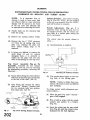
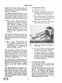
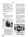
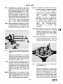
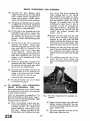
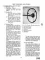
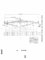
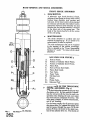
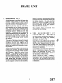
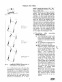
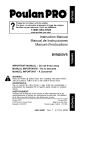
Ghost view of Top Cover AssembIy.
Fin.
- 40
-
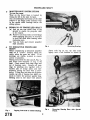
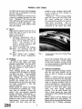
(f) Remove 1st and 2nd speed selector
shaft retaining screw (6), spring and
$" locking ball and slide this selector
shaft fearwards clear of the casting to
enable the removal of the selector
fork.
(g) Remove " Reverse " selector fork and
shaft (9) carrying out the procedure
as in (f) above, excepting that the
shaft is positioned by a plunger,
spring, distance piece and retaining
screw instead of the ball, spring,
and retaining screw.
(h) Remove 3rd and " Top " speed selector shaft (7) and fork, carrying out
the procedure used in (f) above.
(iii) Withdrawing the pivot bolt (3)
to enable the change speed lever
assembly to be withdrawn.
Caution.
When withdrawing
the change speed lever assembly,
ensure that the anti-rattle spring
and retainer, w h c h is located on
the spherical part of the lever,
is retained for re-assembling.
(d) Remove the three wire locked stop
screws (4).
(e) Unscrew and remove the three wire
iocked screwed taper pins ( 5 ) securing
the forks to the selector shafts.
25
201
GEARBOX
SUPPLEMENTARY INSTRUCTIONS FOR INCORPORATING
OVE
VE ON SECOND"
ccTHIRD" GEARS
NOTE. It is important that no
attempt is made to move more than
one selector shaft at a time otherwise
damage will be caused to the bores
of the top cover and difficulty will
be experienced in removing the shafts.
Finally shake out the interlock balls
from the casing.
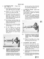
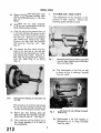
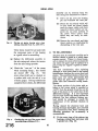
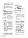
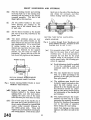
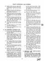
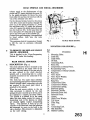
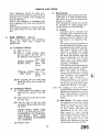
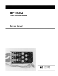
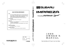
Isolator Switches. The isolator switches,
Fig. 41 (Part No. 42781), are not included
in the top cover assembly (Part No. 502411)
and will therefore be required.
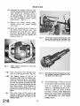
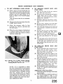
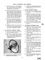
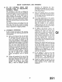
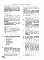
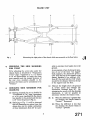
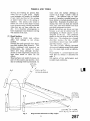
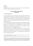
Switch Adjustment. Fig. 42. It is
important when moving the gear lever to
an engaged position, that the switch contacts close at a precise point during the
lever's movement.
Remove the existing isolator switch.
a"
Remove the two
UNF setscrews
(11) from the oil sealing ring cover
plate (12), enabling the plate and
three rubber sealing rings to be
removed.
It being very difficult to remove the
welch plugs (13 and 14) without
damaging them, it is desirable to
replace the old plugs with new ones
when re-assembling the new top cover.
40-To
Top Cover Assembly-Fig.
Assemble. Assemble the new selector
forks into the new top cover by reversing
the dismantling procedure, observing the
following :Ensure before fitting the centre selector
shaft that the interlock pin is positioned
in the end of the shaft. (See 10).
After fitting and moving the centre
shaft to the " Neutral " position, feed
the two interlock balls into position
from either side. (See 10).
L I N K LEAD
PT NO 5 0 2 4 1 2
TOP COVER (&STING
P 1 No 3 0 1 7 6 8
The correct time for contact closure is
when :(a) Synchronisation is complete.
SUBTRACT 0 04"
FROM CAP
Fig. 42
Adjusting the Isolation Switches.
(b) The synchro sleeve begins to cover the
dog teeth of the driving gear.
NOTE. Failure to obtain these conditions will result in noisy a ~ l ddifficult
gear changing.
T o obtain correct switch adjustment proceed as follows :(a) Move the gear lever until " Second "
gear is f d y engaged.
\
(b) Wire a bulb in series with the switch
contacts and connect to a battery.
(Fig. 42).
"
WtlCW PLUGS
PT W 5 4 5 0 5
Fig* 41
150L4TOR 5WllCHS
PT NO a2781
EARTHED BV
SECUQINL BOLT
Top Cover showing Isolation Switches.
(c) Screw the switch into the rear switch
boss (Fig. 42), until the contacts close.
(Indicated by the bulb lighting.)
GEARBOX
SUPPLEMENTAIRY INSTRUCTIONS FOR INCORPORATING
OVERDRIVE ON '"SECOND" AND "THIRD" GEARS
(d) Measure with feeler gauges the gap
between the switch and boss, that is,
the amount the switch would have to
be screwed down to be fully home.
(e) From this dimension subtract .040"
and make up the remainder with
paper packing washers, Part No.
502146.
Example. If the gap measured
.090" the subtraction of the .040"
would leave .05C".
By selection
(the washers vary in thickness) obtain
a pack which measures .050".
(f) Disconnect the switch and remove it
from the top cover.
(g) After installing the washer-pack over
the screwed portion of the switch,
screw the switch securely into the top
cover.
Repeat the procedure with the
" Third " and " Top " isolator switch.
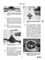
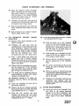
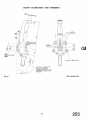
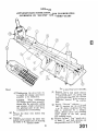
OPERATING
SWITCH
ISOLATOR
SWITCH
W1
t-Part No. 501803 for R.H.
Part No. 502104 for L.H.
(a) Where a car is to be fitted with overdrive on all gears and is already fitted
with a top cover (Part No. 502411).
(b) T o convert cars fitted with the old
type overdrive unit (Serial No. 221
12751-, in which case either :-
TO AMMETER IF FITTED
BROWN WIRE BATTERY SIDE
FITTED, RUN TO BROWN
B BLUE ON HEAD L A M P
SWITCH
Fig. 43
Top Cover Conversion Pack-Part No.
503219. The following is a list of the parts
included in the pack to convert the old
type cover assembly, part No. 502078 to
502411.
301768
1 Top Cover Casting
1 1st and 2nd Selector Fork 110753
1 Top and 3rd Selector Fork 110754
2 Welch Plugs
54505
1 Isolator Switch
4278 1
6 Packing Washers
502 146
1 Link Lead
502412
3 Welch Plugs
104449
These kits may be used either :
TO STARTER SOL SWITCH
WHITE FEED SIDE.
-
Wiring.
The switches are wired in
parallel (Fig. 43) and the necessary link
lead from switch to switch is obtainable
under Part No. 502412.
One of the link wires is connected to earth
(Fig. 41). The remaining link wire is
connected through a snap connector to one
side of the operating switch.
Wiring Diagram.
(i) A complete new top cover assembly, Part No. 502411, may also
be required, or
(ii) A top cover conversion Pack,
No. 503219.
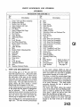
ervice Instr
EAR AXLE
SECTION F
INDEX
Notation for Fig. 2 ......
......
......
......
Data ......
......
......
......
......
......
General description
......
......
......
To remove hubs
......
......
......
......
T o revlace hubs
......
......
......
......
T o rgmove hubs
TO replace hubs
Centre lock type ......
......
......
......
T o remove axle shaft
T o replace axle shaft
......
......
.....
T o remove axle
......
......
......
......
To replace axle
......
......
......
......
T o dismantle axle . . . . . . . . . . . .
......
......
To assemble axle ......
......
......
......
ServiceDiagnosis ......
.....
......
......
Fig . 1
Fig. 2
Fig . 3
Fig . 4
Fig . 5
Fig. 6
Fig . 7
Fig . 8
Fig. 9
Fig . 10
Fig . l1
Fig . 12
Fig . 13
Fig . 14
Fig . 15
Fig . 16
Fig . 17
Fig . 18
Fig. 19
Fig . 20
Fig . 21
Fig . 22
Fig . 23
Fig. 24
Fig . 25
Fig . 26
Fig . 27
Fig. 28
Fig. 29
Fig . 30
Fig. 31
Fig . 32
Fig. 33
Fig. 34
Fig . 35
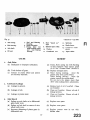
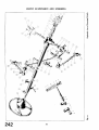
Axle arrangement ......
......
......
......
......
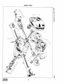
Exploded view of axle details
......
......
......
......
Hub removal
......
......
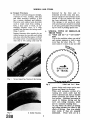
The removal of the '("knock~on" type h$
......
......
The replacing of the “hock-on " type hub ......
......
......
Hub removal.
......
......
......
.....
....
Removing hub bearings ......
......
......
......
......
Replacing hub oil seal
......
......
......
......
......
Replacing hub bearings ......
......
......
......
Axle being removed from car
......
......
......
......
Removing split pin from hub securing nut
......
.....
Identification numbers on bearing caps and axle casing.....
Casing spreader in position
....
.....
.....
.....
Removing split pin from driving flange securing nut ......
Removal of pinion head bearing . . . . . . . . . . . .
......
......
Driving out pinion bearing outer rings ......
......
Checking the run-out of the crown wheel mounuig flange
......
......
......
Fitting pinion bearing outer rings
Pinion setting gauge assembled to axle centre casing ......
The pinion setting gauge is set to zero ......
......
......
Measuring the shim pack ......
......
......
......
Shims placed in position on outer ring abutment'face ......
Pressing the pinion head bearing on to the pinion shaft......
Showing the pinion bearing spacer chamfer pointing
......
......
......
......
outward......
Testing the pre-load'if the pinion.bearings
......
......
Fitting pinion housing oil seal ......
......
......
......
Fitting differential bearings to the differential casing ......
Ascertaining the total end float of the differential unit
without the crown wheel
......
......
......
......
Location of planet gears for entry into differential casing
Ascertaining the depth of engagement between crown
wheel and pinion
......
......
......
......
......
Removal of differential bearings . . . . . . . . . . . .
......
......
Checking the backlash
......
......
......
......
Crown wheel tooth mark&;
......
......
The replacing of the disc wheel
hub""
......
......
ccKnock-on" type hub in exploded form
......
......
Fig. X
Axle arrangement. (For Notes I and 2 See page 4).
REAR AXLE
REAR AXLE
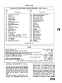
NOTATION FOR REAR AXLE EXPLODED VIEW (FIG.
Ref.
No.
Ref.
No.
Description
2)
Description
Pinion head bearing ring shim.
Pinion bearing spacer.
Pinion tail bearing.
Pinion shaft shims.
Pinion shaft oil seal.
Pinion driving flange.
Castellated nut.
Washer.
Cotter pin.
Rear cover.
Toint washer.
"
Oil filter plug.
Washer.
Rear axle shaft.
Hub bearing.
Hub oil seal.
Bearing housing.
Hub assembly.
Wheel stud.
Splined collar.
Castellated nut.
Washer.
Cotter pin.
See also ' ~ i 35.
g
Axle casing assembly
Breather.
Fibre washer.
Drain plug.
Grease nipple.
Bearing cap.
Bearing cap setscrew.
Tab washer.
Differential bearing.
Shims.
Differential casing.
Sun gear.
Thrust washer.
Planet gear.
Thrust washer.
Cross pin.
Locating pin. (See note 1 page, 4).
Crown wheel and pinion.
Crown wheel bolt. (See note 2, page 4).
Tab washer.
Tab washer.
Pinion head bearing.
I
DATA
......
......
......
Crown wheel run out
......
......
Not more than .003"
Backlash between crown wheel'kd pinion
......
......
......
......
.004" - .006"
......
3.4375"
Distance from ground thrust face on pinion to centre of crown wheel ......
......
15 - 18 in. lbs.
Pinion bearing re-load, measured without oil seal . . . . . . . . . . . .
erential bearings Allowance for .002" to .004" shims, spread over both bearings
Pre-load for
......
......
......
Diameter of differential bearings
......
2.8446" - 2.8440"
2.8460" - 2.8450"
Later prodikon cars
......
Pinion nut tightening torque . . . . . . . . . . . .
......
......
......
85 - 100 lbs. ft.
110 - 125 lbs. ft.
Hub securing nut tightening tor ue ......
125-145 bs. ft. w i t h . i p e c i i k t fi&d t o ' k l e No. TS.8039 onwards.
d$)
9
I.
GENERAL DESCRIPTION (Fig. I )
The rear axle is of the hypoid semi-floating
type with shim adjustment for the differential bearings and for the endwise location
of the pinion in relation to the crown wheel.
The axle sleeves are pressed into the centre
casing and each sleeve is located by four
Pegs.
The centre casing is a casdng which accommodates the differential cage and the
attached crown wheel, together with the
hypoid pinion. A detachable pressed steel
cover, at the rear of the centre casing,
allows access to the differential unit and
crown wheel, the removal of this cover
clears the way for the dismantling of the axle.
The hypoid pinion is mounted on two taper
roller bearings which are separated from
one another by a tubular spacer. The pinion's endwise relation with the crown wheel
is adjusted by means of shims inserted
AXLE
between the " head" bearing outer ring
and the casing. %reloading of bearings is
adjusted by means of skims between the
spacer and tail bearing.
The differential casing contains two sun and
two planet wheels and also carries the crown
wheel, which is bolted in position by ten
bolts passing through the casing and into
tapped holes in the back of the wheel itself.
NOTE 2 : Fig. 1. The crown wheel is
attached to the differential cash
bolts locked by tab washers. The crown
wheel showed a tendency to work
loose after exacting rally acceleration
and reversing gear tests and to obviate this possibility the h'' UNF
attachment bolts were replaced by g"
UNF in axles numbered TS.4731
onwards.
MOVE NUBS
(a) Remove the nave plate.
(b) Withdraw the split pin from end of
axle shaft. Partly release the torque on
the castellated hub securing nut.
( c ) Jack up the car, remove the castellated
nut, the road wheel and by the withdrawal of the two countersunk setscrews remove the brake drum.
) Remove the washer and the splined
taper collar from the axle shaft.
The two planet wheels are mounted on a
cross spindle, this spindle being provided
with a hole at one end and located by a pin
passing through the hole and the diaerential casing.
NOTE 1 : Fig. 1. The locating pin used
has a " stepped " shape but this is to
be changed in the near future to the
"parallel " type pin as shown in the
main illustration. Incorporated in
e No. TS.6260 onwards.
The axle shafts are splined at both ends.
The inner end fitting into the sun wheels
and the outer extremity accommodating the
wheel bearing and hub. The hub is
secured to the splined end of the axle shaft
by means of a S lined taper collar, a shaped
washer and a castellated nut.
The wheel bearing is accommodated in the
axle sleeve and a housing which is bolted to
the flanged end of each axle tube. The inner
portion of the wheel bearing is gripped
between the hub and a flange on the axle
shaft.
The differential casing is mounted on two
taper roller bearings, e position of these
being adjusted by means of shims interposed between them and the casing itself.
The disposition of these shims decides the
crown wheel and pinion depth of engagement and the thickness of these the arncunt
of pre-loaning.
.3
(e)
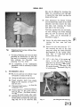
H u b removal utilising the Churchill tool
NO. S 13212.
Fit the Churchill hub removing tool
$6 or S13212 and withdraw the
hub from the shaft (Figs. 3 and 6).
An alternate method is to withdraw
the half shaft with the hub in position
(see page 5), this method necessitates
the removal of the brake backing plate
and the severing of the hydraulic and
hand brake connections.
The replacement of the hubs is the reversal
of the removal but the following notes
should be considered.
The axle shafts of the later production cars
provided an interference fit with the hub
splines. T o facilitate the replacement of
the hubs-the
Churchill hub replacing
Tool No. S125 was introduced (see Fig. 5).
Should the axle shafts be out of the axle
casing it will still be necessary to use the
hub replacing tool or a fly press.
AR AXLE
4.
TO REMOVE HUBS
(Centre lock
type) (Fig* 35)
(a) Jack up the car and remove the hub
cap by-tapping the lugs with a copper
faced mallet. Remove the road wheel.
(b) Remove the split pin through the
aperture in the barrel of the hub.
Remove the hub securing nut from the
axle shaft. It may be necessary to
replace the wheel and lower the car
when torque is applied to the nut.
After removing the nut withdraw the
washer and splined collar.
tates the severing of the hand brake
and hydraulic connections and removing the brake backing plate.
5.
TO REPLACE HUBS (Centre lock
tyI?e> (Fig* 35)
The replacement of the hubs is the reversal
of their removal. However the followinn
points should be noted.
(a) The axle shafts of later production
cars provide an interference fit with
the hubs. T o facilitatethe replacement
of the hubs the Churchill hub replacing
Tool No. S 125 was introduced and is
illustrated in Fig. 5.
(d) By inserting a screwdriver blade into
the cut of the split tapered collar, the
collar will expand and allow it to be
withdrawn from the hub.
(e) Remove the two countersunk brake
drum securing screws and withdraw
the brake drum.
(f) Fit the Churchill hub removing
Tool No. S132 and remove the
hub.
i t should be remembered
that the hubs have right or left-hand
threads and care must be exercised
when selecting the removal rings.
(See Fig. 4.)
Fig. 5
The replacing of the knock on type hub
utilising the Churchill Hub Replacing
Shown with brake
Tool No. S125
assembly removed for photographic
purposes.
When the axle shafts are out of the
casing it is still necessary to use the
hub replacing tool or a fly press.
Fig. q
The removal of the knock on type hub
utilising the Churchill Hub Removing
Rings S132 with the S4221 frame and
slave ring. Shown with brake assembly
removed for photographic purposes.
An alternate method of hub removal is
to remove the axle shaft complete as
described on this page. This necessi-
AXLE SHAFT
Jack up car and remove road wheel.
If the car is equipped with wire wheels
remove the split tapered collar by
inserting a screwdriver blade into the
cut of the ring. It can now be drawn
off the barrel of the hub.
(c) Withdraw the two countersunk brake
drum securing screws and remove the
brake drum.
(d) Drain the hydraulic system, disconnect
the pipe line and the hand brake cable
at the wheel cylinder.
REAR AXLE
(e) Remove the four bolts and nyloc nuts
which secure the brake backing plate
and the bearing housing to the axle
flange.
7.
TO REPLACE AXLE SHAFT
The replacement of the axle shaft is the
reversal of their removal. However the
following points should be noted.
(f) Withdraw the axle shaft assemblv
from the axle casing together with th;
brake backing plate assembly.
(g) Grip the axle in the protected jaws of
a vice and utilising the aperture in the
barrels of the centre lock hub, remove
the split pin. Remove the castellated
nut, washer and splined taper collar.
Remove the hub with the Churchill
hub remover, Tool No. S132. (See
Fig. 4).
(h) T o remove the disc wheel hub, first
remove the split pin at the axle end
followed by the castellated nut, washer
and splined taper collar. Remove the
hub with the Churchill hub remover,
Tool No. M86 (Fig. 6) or S13212
(Fig. 3).
Fig. 7
Removing hub bearing utilising Churchill
Tool No. S4615 Codes 8 and 10 with S421
frame and slave rin~.
(a) The replacement of the hub oil seal
is shown in Fig. 8, utilising Churchill
Tool No. M29.
Fig. 6
Hub removal utilising the Churchill tool
No. M86.
The extraction of each hub will release
h e oil seal and bearing housing but
leave the hub bearing on the axle shaft.
(i) Remove the hub bearing from the
shafts, utilising the Churchill Tool No.
S4615 Codes 8 and 10. (See Fig 7.)
(j)
The oil seal can now be drifted out of
the bearing housing if it is seen to
be unserviceable.
Fig. 8
Replacing hub oil seal utilising Churchill
Tool No. f i g .
(b) Replacement of the hub bearing is
illustrated in Fig. 9, using Churchill
Tool No. M92.
this can be effected by inserting the
blade of a screwdriver into the split
to expand the ring which can then be
First disconnect the Bundy Tubing
and the hand brake cables at the wheel
cylinders and then remove the bolts
and nyloc nuts securing the brake
back plate to the axle casing.
The hubs, together with the half shafts,
oil seals, bearings and brake backing
plate, can now be removed from the
axle. These can be dismantled as
described on page 5.
Remove the axle check straps by first
ving the four nuts and lock
On later production cars the axle shaft
e replacement
necessary to bleed
the brakes.
e axle has to be
'Jack up car and remove roa
nyloc nuts.
g and swing the shock absorber
(attached to the spring plate)
he " U " bolts may now be
1
g.
TO REPLACE T
If a replacement axle is being fitted it will
be necessary to remove the complete brake
assemblies at the axle ends.
It is not necessary to remove the hubs,
for these can be removed with the half
shafts and brake backing plates.
The axle must be tilted during the fitting
operations and filling the axle with oil
should be delayed until the axle has been
fitted to the car.
The fitting is the reversal of the removal.
For the bleeding of the hydraulic system
see " Brakes-Section R."
m. TO DI
E
(a) Drain oil.
(b) Remove wheel securing cones (wire
wheel hubs only). This enables the
brake drum securing screws to be
removed and the drums withdrawn.
(c) Remove split pins (as shown in Fig. 11)
the axle is going to be completely
dismantled the hubs can be removed at
a later stage, which means that the
half shafts, hubs, brake backing plates,
etc., must be removed as an assembly.
(d) Remove brake shoes and return springs.
( e ) Withdraw the brake backing plates
after removal of the eight bolts, spring
washers and nyloc nuts, four from
either back plate. Further dismantling
of the brake backing plates only require
the removal of the hydraulic wheel
cylinders and anchor blocks, the latter
being secured by spring washers and
two nuts, the former can be withdrawn
provided the hydraulic connections,
rubber dust sealing boots, etc., have
been removed.
(f) The half shafts can now be withdrawn
from the axle casing, the bearing housings tapped off the bearings and the
bearings withdrawn with a suitable
puller.
(As shown ia Fig. 7.)
The grease seal can then be tapped out
of the bearing housings.
NOTE : If the hubs have not been previously withdrawn due to dlfficuleies
in slackening the hub nuts mentioned
in (c) they can now be slackened by
gripping the axle shaft in ,the vice,
the hubs then pressed off the
axle shafts with a suitable tool or press.
Fig.
11
Removing split p h from hub securing nut.
and hub securing nuts. Preventing the
hubs from rotating by means of a road
wheel, the conical washers can then be
removed and the hubs, complete with
their splined tightening cones, withdrawn with a suitable tool or press.
Churchill Tool No. M86 or S132/2.
AR AXLE
(g) Remove axle centre casing cover and
joint after withdrawal ofeight setscrews.
) Remove the differential bearing caps,
noting the markings stamped on the top
of these and the correspondingly abutting portions of the casing. The exis
relation between the caps and casing
must be retained when re-assembling.
Fig. 12 shows example of markings.
(i) Apply axle casing spreader as shown
in Fig. 13, and lift differential assembly
Fig. 14
Removing split pin from driving flange
securing nut.
and tail race for possible use when
re-assembling. Remove pinion head
bearing h e r cone as shown in Fig. 15.
Casing spreader h position. Churchill
Tool No. SIQI.
out of the axle centre casing. " Spreading " should be limited to that required
to just free the assembly in the casing.
the respective outer
portion of the differential bearings
with their inner races. The interrelation of the component parts of
these races must be retained when
re-assembhg the rear axle.
Remove the crown wheel from its
mounting flange after the withdrawal
of tke ten fixing bolts, leaving further
dismantling of the
renaial unit
until a later stage.
After removal of split pinned flange
nut as shown in Fig. 14, and having
removed the flange, drive the pinion
out through the casing with a hide
faced hammer. Lay aside the shims
which are fitted between the spacer
Fig. 15
Removal of pinion head bearing utilising
Churchill Tool No. TSI and Sqzzr frame
with slave ring.
(m) Drive out the pinion outer rings as
shown in Fig. 16. The removal of the
outer ring of the tail bearing will also
eject the oil seal and tail bearing inner
cone. The ejection of the head bearing
outer ring will uncover the shims
fitted between this and the casing.
REAR AXLE
assembly can be removed from the
axle casing and dismantled as follows :
(i) Drive out the cross pin locating
pin and withdraw the cross pin.
(ii) Rotate the sun wheels which will
in turn rotate the planet wheels
until the planet wheels with their
respective thrust washers are opposite the cut away portions of
the crown wheel carrier from
which they can easily be withdrawn.
(iii) Remove the sun wheels and their
thrust washers, so completing the
dismantling of the rear axle.
Driving out pinion bearing outer rings
utilising Churchill Tool No. 2oSM F T ~ I .
These shims should be laid aside with
the component parts of this bearing
as a guide when re-assembling.
Replace the differential assembly in
the axle casing and release the tension
from the axle casing spreader.
Check the " run out" of the crown
wheel mounting flange ; this should
not exceed .003" (Fig. 17). The
crown wheel itself can be checked on
a surface table with the aid of a set
of feeler gauges. Having satisfactorily
completed these checks, the differential
Fig. 17
Checking the run out of the crown wheel
mounting flange udllsing a D.T. I.
I1
TO RE-ASSEMBLE
All parts must be examined carellly and a
decision should be made as to which items
require renewal. Where it is found necessary to replace the crown wheel or pinion for
any reason the gears must be replaced as a
pair, as they are "lapped" together in manufacture.
The first consideration, after replacing
damaged or worn parts,must be the correct
interrelations between the crown wheel and
pinion. The assembled relation of these two
gears must very closely approximate that
used when the gears where "lapped" together after heat treatment during manufacture.
The datum position of the pinion with relation to the crown wheel is specified as
3.4375" from the ground thrust face on the
back of the pinion to the centre line of the
differential bearings. It is also important
that not only should this datum position be
achieved, but that sufficient bearing preload should be arranged to ensure the
maintenance of the specified relations in
service.
Having cleaned the abutment faces and
bearing housings thoroughly, and removed
any excrescences from these surfaces, the
following procedure for re-assembly is
recommended.
(i) Fit the outer rings of the pinions two
bearings, pulling them into place with
a special tool. (Fig. 18).
REAR AXLE
Fig. 18
Fitting pinion bearings outer rings utilising Churchill Tool No. M70.
Fig.
20
(ii) Fie the dummy pinion (M.84), the
pinion bearing inner cones and install
into the axle centre casing ;tightening
the flange nut progressively until the
correct pinion pre-load of 15-18in.
lbs. is obtained.
is required under the pinion head bearing outer ring, to bring the pinion into
its correct datum position mentioned
earlier. Due to the fact that the
bearing inner cones are a slide fit on the
dummy pinion and a press fit on the
actual pinion to be used, bearing expansion will undoubtedly take place in the
latter case. A pack of shims .002",003"below the gauge reading will be
required to allow for this expansion and
thus ensure the pinion is in its correct
datum position.
(iii) Install the pinion setting gauge in
the axle centre casing (Fig. 18), (after
zeroing the dial with a ground button
held firmly on the gauge plunger, Fig.20)
and tighten bearing caps. This gauge is
used to assess the shim thickness which
Fig. 19
Pinion setting gauge, Churchill Tool No.
M& assembled to axle centre casing.
Utilising the '' button ",the Pinion Setting
Gauge (Churchill Tool No. M84) is set to
zero.
Fig.
21
Measuring the shim pack.
F
(iv) Although the packing shims are supplied to nominal thicknesses, the dimensions should be measured with a
micrometer gauge. It is important that
no damaged shims are used and that
they are thoroughly cleaned before
measurement. (Fig. 2 1.)
(v) Remove the pinion setting gauge,
dummy pinion and pinion bearing
outer rings.
(vi) Insert the measured pack of shims on
the pinion head bearing outer ring
abutment face (Fig. 22) and replace
the pinion bearing outer rings, pulling
them into place with the special tool
shown in kg.18.
Fig.
22
Fig.
23
Pressing the pinion head bearing on to the
pinion shaft utilising e Churchill Tool
No. %SEand S4221frame with slave ring.
Shims placed in position on outer ring
abutment face.
(vii) Press the pinion head bearing '
cone on to the pinion shaft (Fig
(v=) The bearing spacer is fed on to
the pinion shaft with the chamfer outwards as shown in Fig. 24. The shims
removed when dismantling
in position on the
embly fitted into the
The thickness of
robably have to be
adjusted to provide the correct pre-load
figure.
(h> The h e r cone of the pinion tail
bearing is tapped kit
pinion and up ag
distance mllar.
inion bearing spacer cham-
(X)
The driving flange is fitted on the end
of ahe pinion shaft and
the castellated nut and plain
washer to a tightening torque of 85100 lbs. ft. TPIE OIL SEAL IS NOT
FITTED UNTIL
I N THE NEXT
AR AXLE
Fig. 25
Testing the pre-load of the pinion bearing
utilising the Churchill Tool No. m S M . 98
Note : The oil seal is not fitted at this
juncture.
(xi) The fixture shown in Fig. 25 is now
applied and the pre-load of the bearings
checked. The correct pre-load should
fall between 15-18 in.lbs. If the preload is inadequate shims must be withdrawn, whereas if an excessive figure
is obtained additional shims must be
fitted.
(xii) When the correct pinion pre-load is
obtained remove driving flange and fit
the oil seal (Fig. 26), after which the
Fig. 26
Fig. 27
Fitting differential
utllislnb the
Churchill Tool No. M 8 9 to the differential
casing.
(xiv) The axle bearing seats are carefully
cleaned and any excresences removed.
The differential casing is positioned
and the bearing caps, fitted with
regard to the identification markings,
are tightened down and then slackened off a $ turn. This will prevent
the bearings tilting but allow sideways
movement. A dial indicator gauge is
mounted on the axle centre casing with
the plunger resting on the crown wheel
mounting flange (Fig. 28). The assembly is forced away from the dial
gauge and then the indicator set to
zero. The assembly should then be
Fitting pinion housing oil seal utilising
Churchill Tool No.
flange should be replaced, the castellated nut tightened to the correct
torque and split pinned.
(xiii) The differential assembly bearings are
now fitted without, as yet, installing
any packing shims. A suitable driver
such as that which is shown in Fig. 27
should be used for driving the bearings
on to the crown wheel carrier.
Fig. 28
Ascertaining the to
end float of the
differential casing
thout the crown
el fitted. The caps should be tight
then slackened 4 turn.
I
REAR AXLE
levered in the opposite direction until
the taper roller bearings go hard home.
The reading on the dial gauge (.062"
for example) will indicate the total
side float of the crown wheel carrier
and should be noted for later reference.
(xv) The crown wheel carrier is now removed from the axle centre casing so
that the sun gears, planet gears and
thrust washers can be assembled, the
cross pin being used to locate the two
planet gears with their respeceive thrust
washers temporarily in position (Fig.
29). Subsequently, the planet gears are
Fig. 29
Location of planet gears'forentry into the
differential casing.
rotated round the sun wheel through
90 degrees, the cross pin being withdrawn to allow the gears to assume
their normal fitted position, and the
cross pin finally fitted and secured by
its locking pin, this pin being located
by <'centre popping."
(xvi) The crown wheel is fitted to the crown
wheel carrier, the fixing bolts
thoroughly tighten to 22-24 lbs. ft.
and secured with their respective locking plates.
NOTE : The crown wheel attachment
bolts were increased in diameter from
h''to 8'' at rear axle No. TS.4731.
The crown wheel is checked for flush
fitting against the flanged face of the
carrier with a feeler gauge, thus ensuring
that the crown wheel goes right home
and also that there can be no question
of casting distortion. The maximum
permissible run out of the crown wheel
and crown wheel mounting flange is
.003". The flange can be checked
before the fitting of the crown wheel
by rotating it on its bearings, using a
dial indicator, the crown wheel itself
on a surface table with the aid of feeler
gauges.
(xvii) The differential assembly is installed
in the casing in a similar manner to
operation (xiv), but in this instance
the D.T.I. plunger bears against the
back of a crown wheel fixing bolt
(Fig. 30).
Fig. 30
Ascertaining the depth of engagement
between crown wheel and pinion.
(xviii) The assembly is now forced away from
the dial gauge until the teeth on the
crown wheel go M y home with those
on the pinion. The dial gauge is now
set to zero and the assembly levered
towards the dial gauge. Let this dimension be .045".
( K ~ x )The side float of the assembly measured
in the last operation, less the crown
wheel and pinion backlash specified,
will indicate the shim thickness required on the crown wheel side. The
backlash is specified as between .004"
and .006" and an average figure of .005"
should be used for this calculation
giving .040" to be fitted on the crown
wheel side.
REAR AXLE
T o obtain the thickness of the shims
required between the other differential
bearing and casing, the figure arrived
at in previous operation, i.e., .040",
should be subtracted from the total
side float measured in operation (xiv),
plus an allowance of .005" to provide
the necessary degreeof bearing pre-load.
This gives a total shim thickness of
.067" and thus shims on two bearings
will be .040" already estimated and
.067" - .040"=.027" on the other side.
Having decided the thickness of shims
required behind each differential bearing, these bearings are extracted with
the special tool shown in Fig. 31. The
Fig. 31
(xxiv) The differential assembly is now fitted
into the axle centre casing and, owing
to the pre-loading of the bearings, a
certain amount of casing spreading is
desirable to complete this operation.
THE
CASING
SPREADER
SHOWN I N FIG. 13 SHOULD
BE USED AND THE SPREADING
OF THE CASE LIMITED T O
THAT JUST REQUIRED T O ENABLE
THE
DIFFERENTIAL
ASSEMBLY T O ENTER THE
CASING.
(xxv) The bearing caps are then fitted in
their respective -positions so that the
number stamped on the caps coincide
with those stamped on the axle casing,
tightening them to their correct torque
of 34-36 lbs. ft.
(xxvi) The pinions and crown wheel backlash
is checked witha dial gauge as shown in
Fig. 32, and should be .004"-.006" : an
averageshould be taken of several teeth.
Removal of the differential bearing utilis ing the Churchill Tool No. S103 and S4221
frame.
respective shim packs are measured
with a micrometer gauge after ensuring
that the shims are clean and undamaged
and allocated to their respective sides
of the crown wheel carrier.
(xxii) As each bearing is extracted, the two
~ortionsof each must be laid aside for
;efitting in the same relation and position as that used during initial assembly.
Failure to fit these bearings in their
original positions will upset the
measurements made in previous operations.
(xxiii) Having fitted the two packs of shims
in their respective positions the bearing
inner cones are driven on to the carrier
with a suitable sleeve tool as shown in
Fig. 27 and the outer rings applied.
Fig. 32
Checking the back lash of the differential
unit utilising a DTI.
Should the backlash be incorrect, the
transfer of shuns from one side of the
differential carrier to the other will be
necessary. If the backlash is too great,
then a shim or shims will have to be
taken from the side opposite the crown
wheel and the same shims added to the
crown wheel side, always maintaining
-.PI
REAR AXLE
the same overall total. Should the backlash be insufficient, then the reverse
procedure must be adopted.
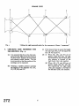
A tooth marking test should now be
carried out, and to enable this to be
done a few teeth should be painted with
a suitable marking compound. The
pinion should be rotated backwards
and forwards by the driving flange,
over the marked teeth on the crown
wheel, azld the markings compared
with the diagram (Fig. 33), and the
instructions on this diagram regarded.
HYPOID CROWN WHEEL TOOTH MARKINGS
DRIVE SIDE
OVERRUN SIDE
CORRECT MARKINGS ON GEAR
The hubs are next fitted by means of a
special tool or press (Fig. 34), and
secured by the splined hub tightening
cones, conical washers and hub securing nuts. A substantial spanner will be
required to tighten the castellated
securing nut. (A tightening torque of
110-125 lbs. ft. is specified. After
axle No. TS.8039 the torque was
increased to 125-145 lbs. ft. when a
nut of a different material was introduced.) Having thoroughly tightened
up this nut, the hole in the axle shaft
is lined up with one of the slots in the
castellated nut and the split pin is
fitted.
The brake drum is next fitted to each
hub and secured thereto by means of
the two countersunk grub screws.
Fit wheel securing cones (wire wheel
hubs only). Fig. 35.
Fig. 33
(
PlNlON CONE
TOO CLOSE
PINION CONE
TOO WIDE
Crown wheel tooth markings.
) A new axle cover pa
together with the cover itself, and the
latter secured with the eight setscrews.
Drive the wheel bearings on to their
respective axle shaft (Fig. g), and
assemble to the
The grease seals should now be tapped
into the bearing housings (Fig. B),
and the assem lies fitted to each axle
sleeve, followed by e brake backing
d shoe assembly.
The four bolts are fitted through each
brake backing
0th these items
te relation with
The replacing of the disc wheel type hub
utilising the Churchill Hub ~eplacing
Tool No. S125
SEWMCE DIAGNOSIS
Rear axle noise is usually apparent as a
hum in moderate cases or as a growl in very
severe cases.
Noises from the rear wheel bearings, propeller shaft bearing or tyres is ofien diagnosed as rear axle troubles.
Always ascertain that the noise attributed to
the rear axle does actually emanate from
at unit before dis
"Knock on " type hub.
I.
2.
Seal and Bearing
Housing.
6. Brake assembly.
for
7. Fixing bolts
brake backing plate
and seal / bearing
housing.
5.
Axle casing.
Hub bearing.
3. Axle shaft.
4. Oil seal.
8. Hub '"kack
0d9
type.
g. Splined taper collar.
11.
Castellated nut.
Split
- -pin.
13. Brake drum.
12.
14. C o u n t e r sunk
screws.
IS. Taper collar.
CAUSE
I.
Axle Noise
Inadequate or improper lubrication.
Teeth broken o
Contact of crown wheel and pinion
not correctly adjusted.
(a) Leakage in general.
) Leakage at hub.
e at pinion head.
Splines on axle shafts or in differential
gears badly worn.
Splines on hub shell or centre of wire
wheel badly worn.
Incorrect shimming of planet gears in
differential unit.
Drain, flush casing out with flushing
replenish with correct grade
ee "General Data" Section A.
Replace damaged parts.
Noise during coasting ; move the
pinion away from crown wheel.
Noise during driving ; move the
pinion toward the crown wheel.
Do not move the pinion more than
.004" when making these adjustments.
Reduce level of oil if overfull. Clean
out breather.
Clean out breather. enew oil seal if
leakage persists.
Clean out breather. Renew oil seal if
leakage persists.
Replace w o n parts.
Replace present ones in use with
thicker ones.
ON
U
AND
N
FRONT SUSPENSION AND STEERING
FRONT SUSPENSION
INDEX
Front Suspension Data
......
......
......
......
Description ......
......
......
......
......
......
Notation for Fig . 2
......
......
......
......
Maintenance ......
......
......
......
......
......
Front Wheel Alignment ......
......
......
To adjust Front Wheel ~ l i ~ n m e n t " " " ......
......
Steering Lock Stops
.....
......
......
......
To set Steering Lock Stops
......
......
To remove Front Hub and Stub Axle ......
......
To replace Front Hub and Stub Axle ......
......
To remove Front Shock Absorber
......
......
To fit Front Shock Absorber
......
......
......
To remove Front Road Spring ......
......
......
To fit Front Road Spring ......
......
......
......
To remove and dismantle Front Suspension Unit
To assemble and fit Front Suspension Unit
......
Page
3
STEERING
INDEX
Notation for Fig . 11
......
......
......
Type and Description
......
......
......
Maintenance . . . . . . . . . . . .
......
......
......
Adjustment of Steering Box
To remove Control Head and tat& ~ u d e ' '
To fit Control Head and Stator Tube ......
T o remove Steering Wheel
......
......
To fit Steering Wheel
......
......
......
To remove Steering Unit . . . . . . . . . . . .
......
To fit Steering Unit
......
......
To dismantle Steering ~ n i ; " " ' ......
......
To assemble Steering Unit
......
......
To remove and replace Drop Arm
......
T o remove Idler Unit
......
......
......
To fit Idler Unit ......
......
......
......
Steering Column Bracing . . . . . . . . . . . .
......
TELESCOPIC STEERING UNIT
INDEX
Description ............
......
......
......
......
......
To fit Telescopic Steering unit ......
......
......
......
......
To remove Telescopic Steering Unit
To remove Control Head from ~elesco~ic'(~djust~b1e)
steering Wheel
To fit Control Head to Telescopic (adjustable) Steering Wheel
Steering Stiffness ......
......
......
......
......
......
Assessment of Accidental Damage
......
......
......
......
FRONT SUSPENSION AND STEERING
ILLUSTRATIONS
Fig. 1
Fig. 2
Fig. 3
Fig. 4
Fig. 5
Fig. 6
Fig. 7
Fig. 8
Fig. 9
Fig. 10
Fig. 11
Page
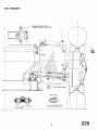
Front Suspension arrangement
1
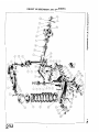
Exploded details of Front Suspen...... 4
sion Unit ......
......
......
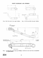
Outer Tie-rod assembly
......
6
Showing use of Wheel Turning
Measure for setting wheel lock.
7
V. L. Churchill Tool No. 121U
Section showing Rubber Bushes
......
8
at lower end of dampers
Front Road Spring being removed,
utilising the Churchill Tool No.
......
......
......
M50
......
9
The Front Suspension Unit
......
...... 10
partially dismantled
Section showing Rubber Bushes
Inner Fulcrum-Top Wishbone 11
Section showing Rubber Bushes
Inner Fulcrum-Lower Wishbone 12
Section through Outer Shackle
Pin-Lower Wishbone . . . . . . . . . . . . 12
Exploded view of Steering details 14
Fig. 12
Fig. 13
Fig. 14
Fig. 15
Fig. 16
Fig.
Fig.
Fig.
Fig.
Fig.
17
18
19
20
21
Fig. 22
Fig. 23
Page
Removing the Sreering Wheel,
utilising the Churchill Tool No.
......
2OS.3600 ......
......
Showing the removal of the l7
18
Steering Unit from front of car
Diagrammatic view showing the
angular position of the Drop Arm
The Telescopic (adjustable)
Steering Unit ......
......
......
The Circlip in position on the
Inner Steering Column...... ......
The Idling Lever
......
......
The Steering Drop Arm
...
The Steering Lever
......
......
The Vertical Link
......
......
The R.H. front and L.H. rear
Upper Wishbone......
......
......
The L.H. front and R.H. rear
Upper Wishbone . . . . . . . . . . .
......
The R.H. front and L.H. rear
Lower Wishbone. The R.H. rear
and L.H. front are symmetrical
but opposite handed ......
...... 26
GI
ONT SUSPENSION
RUBBER FULCRUM BUSHES
SECTION SFOWING RUBBER
WSHES LOWER END OF DAMPERS
SECTION SHOWING RUBBER BUSHES
MNER FULCRUM-TOP WISHBONE.
Fig. I Front Slls
RUBBER BEAR1,NGS
SECTION THRO'OUTER SHACKLEPINLOWER WISHBONE.
SECTION SHOWING RUBBER BUSHES
LOWER WISHBONE-INNER FULCRUM
Iy
l
FRONT SUSPENSION AND STEERING
FRONT SUSPENSION DATA
45"
Track at Ground (Static Laden)
Castor Angle
......
......
Nil
King pin 1nclinati0h
(Static Laden)
......
7"
Wheel Camber (Static Laden) ....
2"
z1 0
Wheel Camber (Full Bump 3")
Wheel Camber
......
1"
(Full Rebound 2.25")
......
......
32'
Turning Circle ......
Back Lock
......
......
......
31"
......
......
28.5"
Front Lock
A 20" Back ~ o c gives
k an 18.75"
Front Lock.
Front Wheel
Alignment
Parallel to 9" toe in
......
19.44"
Length of Centre Tie Rod
Length of Outer Tie Rod
7.68"
End Float of Lower Outer ~ h a c g e
...... .004" to .012"
Pin Assembly
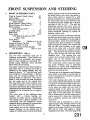
DESCRIPTION (Fig. I)
The two front suspension units are of
wishbone construction. Road shocks are
absorbed by low periodicity coil springs,
each of these springs are controlled by a
double acting telescopic shock absorber
fitted inside the coil spring.
The upper wishbones are rubber bushed at
their inner ends to a fulcrum pin which is
attached to the spring housing, they are
shaped to form a "U" and the outer ends
are interlaced to accommodate a distance
piece and are secured together by the
screwed shank of a ball joint. This joint is
fitted to, and provides the axial movement
for, the upper end of the vertical link.
The inner ends of the lower wishbone arms
are rubber bushed on each side and are
attached to the fulcrum pin mounted on the
upperside of the chassis frame. The fulcrum
is steadied at its extremities by two support
brackets.
The outer ends of the wishbone arms,
bushed with a Clevite bearing, are
mounted on either end of a shackle pin.
The shackle pin is s p h e d centrally to fit
transversely into the manganese bronze
trunnion which is threaded to accommodate
the lower end of the vertical link.
Each bushed end of the wishbone arms is
located sideways on the shackle pin by
means of a white metal covered steel thrust
washer, bearing on the screwed trunnion on
the inside and on the outer side against a
steel washer which is secured by a split
pinned castellated nut. During production
the outer lower ends of the wishbone arms
are assembled to the shackle pin to give an
end float of .004 to .012". The need for
adjustment should only occur when the
front suspension units have been disturbed.
Road dirt and weather are excluded from the
grease lubricated bearings by special oil
resisting rubber seals.
The screwed trunnion at the lower end and
the ball joint at the upper end of the vertical
link provide the bearings for the pivoting of
the road wheels. Road dirt and weather are
excluded from these bearings by a rubber
gaiter interposed between the vertical link
and the ball joint assembly at its upper
end, at the lower end a circular rubber
seal is fitted between the trunnion and the
link. The thread of the trunnion is sealed
off by a disc let into the lower end of the
threaded bore. The steering lock stop
consists of an eccentric roller bolted to the
upper side of the trunnion and abuts
against a machined face on the vertical link.
The vertical link, which couples the upper
and lower wishbone arms as previously
described, is a carbon steel stamping and
carries the stub axle shaft, the brake backing
plate and the steering lever.
The stub axle is of manganese molybdenum
steel, which is mounted as a press taper fit
in the vertical link3is secured by a split pin
locked castellated nut.
The brake backing plate, with the brake
shoes and hydraulic wheel cylindersattached,
is secured to a machined flange on the vertical link by two setscrews with a lock plate
at the lower two points and two bolts of
unequal length at the upper two points.
The longer of these bolts passes through the
front bore of the brake plate, the vertical
link3a distance piece and the steering lever
and is secured by a nyloc nut; the shorter
bolt is similarly secured and utilises the
lower bore.
The front hub is mounted on a air of
opposed taper roller bearings carried on the
stub axle shaft. The inner bearing abuts
against a projecting shoulder on the vertical
link and its outer ring against a flange
machined in the hub. The outer ring of the
FRONT SUSPENSION AND STEERING
r-
FRONT SUSPENSION AND STEERING
NOTATION
Ref.
No.
1.
2.
3.
4.
5.
6.
7.
8.
9.
10.
11.
12.
13.
14.
15.
16.
17.
18.
19.
20.
21.
22.
23.
24.
25.
26.
27.
28.
29.
30.
31.
32.
33.
34.
35.
36.
37.
38.
39.
40.
Description
Inner Upper Fulcrum Pin.
L.H. Front Upper Wishbone Arm.
R.H. Front Upper Wishbone Arm.
Rubber Bush.
Plain Washer.
Castellated Nut.
Split Pin.
Upper Wishbone Ball Joint Assembly.
Grease Nipple.
Rubber Gaiter.
Upper Wishbone Distance Piece.
Vertical Link.
Castellated Nut.
Plain Washer.
Steering Lever.
Bolt.
Bolt.
Steering Lever Distance Piece.
Nyloc Nut.
Setscrew.
Locking Plate.
Stub Axle.
Castellated Nut.
Plain Washer.
Split Pin.
Oil Seal.
Front Hub Inner Bearing.
Front Hub.
Wheel Stud.
Grease Nipple, fitted up to Commission
No. TS.5348.
Front Hub Outer Bearing.
Castellated Nut.
"D " Washer under nut.
Split Pin.
Grease Retaining Cap.
Bottom Trunnion.
Steering Lock Stop.
Bolt for Steering Lock Stop.
Spring Washer.
Grease Nimle.
outer bearings bears against the flange
machined in the hub and the inner cone of
the race against a "D" washer, all are
secured to the stub axle by a castellated nut
and split pin. These bearings are adjusted
by the castellated securing nut but are not
pre-loaded.
Provision is made against the loss of grease
by fitting a felt washer between the vertical
Link and inner bearing.
No.
Description
41. Oil Seal.
42. L.H. Front Lower Wishbone Arm
Assembly.
43. R.H. Front Lower Wishbone Arm
Assembly.
44. Bush for Wishbone Arm.
45. Grease Nipple.
46. Spring Pan Studs
47. Thrust Washer.
48. Lock Washer.
49. Grease Seal.
50. Castellated Nut.
51. Split Pin.
52. Rubber Bush.
53. Support Bracket.
54. Nyloc Nut.
55. Bolt.
56. Nut.
57. Lower Spring Pan Assembly.
58. Bolt.
59. Bump Rubber.
60. Castellated Nut.
61. Cotter Pin.
62. Front Road Spring.
63. Rubber Washer.
64. Packing Piece.
65. Shock Absorber.
66. Lower Rubber Mounting.
67. Upper Rubber Mounting.
68. Metal Sleeve.
69. Washer.
70. Nut.
71. Lock Nut.
72. Shock Absorber Bracket and Fulcrum
Pin.
73. Shock Absorber Bracket.
74. Setscrew.
75. Tab Washer.
76. Nut.
77. Rebound Rubber.
3.
MAINTENANCE
The maintenance necessary is largely confined to periodical greasing (see Lubrication
Chart in General Data Section "A".
The hub bearings are not pre-loaded and it
will be necessary to ensure this condition is
attained when carrying out adjustments (see
Page 7).
FRONT SUSPENSION AND STEERING
As a precautionary measure it is most
desirable to check that an end float of
.004" to .012" in the lower outer wishbone
arm attachment to the shackle pin is maintained. Each arm is adjusted independently.
Apart from damage at this point, tightness
at this point can appreciably affect the ride
of the car (see page 12, para. xi).
Front wheel alignment of parallel to h" toe
in should be checked if the front wheel
alignment is in doubt (see below).
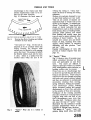
FRONT WHEEL ALIGNMENT
The track should be between parallel and 4"
toe in.
The outer tie rods are adjustable for length
and usually to give the correct track the
distance between the centres of the ball
joint assembles will be 7.68".
If the wheel alignment is in doubt and a
check is to be made it will be necessary to
satisfy the following initial requirements :
Tyre pressures are correct for all tyres.
The amount of wear on both front tyres
must be the same.
The front wheels are true and in
balance.
The checking floor must be level.
The car is in the static laden condition.
A D J U S T F R O N T WHEEL
ALIGNMENT
With the car satisfying the initial
requirements, set the front road wheels
in the straight ahead position and push
the car forward a short distance.
Check the alignment of the wheels with
a Dunlop Optical Gauge or similar
instrument.
If only a fractional correction is necessary it can be made on the outer tie.rod
on the opposite side to the steering box.
T o carry out this adjustment it is first
necessary to loosen the two lock nuts
and turn the tube to shorten or lengthen
the tie-rod assembly. Lock the tube by
the two nuts and move the car forward
half a revolution of a wheel and check,
and make a further adjustment if
necessary.
(e) If an appreciable amount of maladjustment has to be corrected, check first the
length of the outer tie-rods. Should
these lengths be equal make the necessary correction to both. When they are
found to be of unequal length first
correct the rod nearest the steering box
to 7.68" and then make any adjustment
to the further one. After making such
adjustments it is a wise precaution to
measure the length and if found to
differ greatly from 7.68" the front
suspension should be checked for accidental damage.
1
L H THREAD
R H THREAD
1
,.,
TIE-ROD
Fig. 3
6.
Outer Tie Rod Assembly.
STEERING LOCK STOPS
The steering lock stop consists of an eccentric roller mounted on each bottom trunnion
by means of a setscrew and lock washer.
It is most important that the steering lock
stops come into action before the conical peg
of the rocker shaft follower reaches the end
of its cam path. This movement is not more
than 33" either side of the mid point of the
cam and will allow the steering wheel to
travel approximately 2a turns from lock to
lock.
The correct adjustment of the lock stops
should allow a "Back lock" of 31" and a
"Front lock" of 284".
When checking this adjustment it is necessary to satisfy the following initial requirements.
(a) The tyre pressures must be correct for
all four tyres.
(b) The testing ground must be flat.
(c) Car must be in the static laden
condition.
FRONT SUSPENSION AND STEERING
7.
TO SET STEERING LOCK STOPS
(a) Select a space of level ground and run
the car gently forward so that the front
wheels run on to the Churchill Turning
measure and the back wheels on to
blocks as high as the Churchill gauge
(Fig. 4).
This will ensure that the car maintains
its level.
8.
TO REMOVE FRONT HUB AND
STUB AXLE
Jack up the front of the car, remove
nave plate and road wheel.
Remove grease retaining cap and grease
nipple from end of hub. Grease
nipples were discontinued after Commission No. TS.5348.
Withdraw split pin and remove castellated nut and washer from end of stub
axle.
Remove hub, utilising Churchill Hub
Removing Tool No. M.86 or S. 132.
The outer hub bearing can be removed
when the hub is released from the hub
remover.
Remove the four nuts, spring washers
and bolts securing the hub grease
catcher to the brake backmg plate.
Remove the inner wheel bearing from
the stub axle, followed by the grease
seal.
T h e stub axle can be removed from the
vertical link if so desired by the removal
of the split pin, castellated nut and
plain washer from the inner side of the
vertical link.
9.
TO REPLACE FRONT HUB AND
STUB AXLE
Fit the stub axle to the vertical link and
secure with the plain washer, castellated nut locked by a split pin on the
inner side of the vertical link.
Seat the grease seal on its spigot of the
vertical link with the felt pad towards
the centre of the car, followed by the
inner wheel bearing.
Place the hub grease catcher in position
in such a manner that the shaped end
of the pressing is below the vent hole in
the brake backing plate. Secure grease
catcher to backing plate with four
screws, spring washers and nuts.
Fit the hub and outer bearing followed
by the " D " aperture washer and attach
castellated nut.
.justmentof the Front Hubs
These front wheel bearings should not
be pre-loaded.
T h e castellated nut should be tightened
to a torque loading of IOlbs. ft. and
then slackened off 14 to 2 flats according to the position of the split pin hole.
(b) Measure the wheel movement from the
straight ahead position.
(c) Adjust the eccentric roller by first
loosening the setscrew and then t u n
the roller itself.
(d) When the correct degree of adjustment
is attained, tighten down the setscrew
so that the roller will remain in contact
with the vertical link.
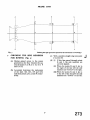
Fig. 4 Showing Use of Wheel Turning Measure
for setting Steering Lock-V.L. Churchill
Turning Measure Tool No. IZIU.
N O T E : If it is impossible to obtain
the correct lock positions by adjustment
of the steering lock stop, this condition
will indicate either a damaged steering
drop arm, steering lever, or in rare
cases, a fault in the steering unit. Where
such difficulties do arise steps must be
taken to diagnose the cause and necessary replacements fitted.
FRONT SUSPENSION AND STEERING
T h e hub bearings are now considered
to be correctly adjusted and the castellated nut can be locked with the split
pin.
(f) Fit the grease retaining cap and grease
nipple to hub, and grease hub.
(g) Replace road wheel and nave plate.
Remove lifting jack from under front of
car.
10.
11.
TO REMOVE FRONT S
ABSORBER
(a) Jack up the car, place supporting stands
under the chassis frame and remove
lifting jack. Remove road wheel.
(b) Partially compress the front road spring
by placing a small lifting jack under the
spring pan.
(c) Remove the lock nut and nut from
upper end of shock absorber, followed by a plain washer and upper
rubber mounting.
(d) Detach the rebound rubber and its
bracket from the side of the chassis
frame after removing the nuts, lock
washers and two long bolts.
(e) Remove the lifting jack from below the
spring pan.
(f) Remove the four nuts and lock washers
from the underneath and centre of the
spring pan. After withdrawing the rebound rubber abutment plate the
shock absorber can be withdrawn
through the spring plate.
(g) After removing the shock absorber
from the car, its lower attachment
brackets can be removed.
Lift the
tabs of the locking plate and remove
the setscrew followed by one bracket
and a rubber bush.
(h) The second bracket is removed from
the shock absorber together with the
rubber bush, the latter can be withdrawn from the fulcrum pin of the
bracket assembly.
TO FIT SHOCK ABSORBER
(a) Examine all rubber bushes to ascertain
that they are in good order. Also ensure
that the fulcrum pin is securely welded
to the shock absorber attachment
bracket.
SECTION SHOWING RUBBER
BUSHES. LOWER END OF DAMPERS.
Fig. 5
Section showing Rubber Bushes at lower end
of Dampers.
) Press a rubber bush on to the fulcrum
pin attachment bracket and feed this
assembly, bush first, into the eye of the
shock absorber. Press a second rubber
bush on to the protruding fulcrum pin.
( c ) Position second attachment bracket
with the tab washer and secure
with the setscrew. Turn over tab of
washer.
(d) Place a large plain washer in position
on the upper end of the shock absorber
followed by a rubber mounting (spigot
uppermost) with the metal sleeve in its
centre.
(e) Feed the shock absorber assembly
through the spring pan in such a manner that the two attachment brackets
locate on the studs of the spring pan
assembly and at the same time the
upper attachment will pass through the
spring abutment on the chassis frame.
It may be necessary to compress the
road spring by placing a jack under the
lower wishbone assembly.
(f) Attach the second rubber mounting
(spigot downwards) to the upper end
of the damper which is protruding
through the chassis frame, threading
it on to the metal sleeve and followed
by the plain washer and securing nut.
(g) Tighten this nut sufficiently to nip the
plain washers and metal sleeve and lock
with a second nut.
SUSPENSION AND STEE
Place the rebound rubber abutment
plate in position on the lower attachment studs (welded to the spring pan)
with the apex of the wedge pointing
towards the centre of the car. Secure
with nuts and lock washers.
Utilising two long bolts, nuts and lock
washers secure the rebound rubber and
its bracket to the chassis frame.
Remove the lifting jack from under the
lower wishbones and replace the road
wheel.
Jack up front of car to remove support
stands, finally remove jack.
TO REMOVE FRONT ROAD
SPRING
(a) Remove front shock absorber as described on page 8.
) Withdraw the split pins from the
castellated nuts on the underside of the
lower wishbones. Remove the centre
nut and bolt from the front wishbone
arm and the bumv rubber assemblv
from the rear wishbone arm. ~ e e d
two guide pins into the vacant holes.
(c) Place a small lifting jack under the
spring pan, with a suitable packing
between jack and pan to prevent damage to the shock absorber attachment
studs on the latter.
(d) Remove the four remaining nuts securing the spring pan to the wishbone
arms and lower jack, easing the guide
pins through the wishbone arms.
(e) The spring can be withdrawn from its
upper abutment together with rubber
washers and distance piece.
An alternative method is to utilise the
Churchill Tool, No. M50 in the following
manner :(a) Carry out operation (a) sand (b) as
previously described.
(b) Remove the fly nut, bearing and plate
from the threaded rod of the Churchill
Tool followed by the " C" washer.
(c) Feed the rod, notched end first,
through the spring pan and upper
shock absorber abutment, to the protruding end fit the "C" washer.
Fig. 6 Front Road Spring being removed, utilising
the Churchill Tool No. M.50.
) Feed the plate on to the threaded
portion of the rod protruding from the
spring pan in such a manner that the
bearing seat is downwards, ensure too
that the holes in the block locate on
the studs of the spring pan.
(e) Feed bearing on to threaded rod followed by the fly nut, tighten to compress spring a small amount.
(f) Remove the four remaining nuts securing the spring pan to the wishbone
arms.
(g) By slowly - unscrewing the fly nut the
spring pan can be lowered down the
(h) When all tension is released from the
road spring the guide pins and the " C "
washer can be removed from the upper
end of the shaft.
(i) Withdraw the Churchill Tool from the
suspension unit together with the
spring pan, spring, rubber washers and
distance piece.
13. TO FIT ROAD SP
(a) Attach the rod of the Churchill Tool
No. M50 to the s ~ h gabutment
bracket of the front ^sus<ension unit
and fit the guide pins through the
centre holes of the lower wishbone
arms.
~
~
FRONT SUSPENSION AND STEERING
Assemble the alloy distance piece
(spigot downward) on the road spring
with a rubber washer interposed between, and position a second rubber
washer on the spring's lower extremity.
The spring and distance piece assembly
is offered up to the front suspension
unit followed by the spring pan, the
latter located on the guide pins.
Fit the plate to the threaded rod of the
Churchill Tool in such a manner that
the bearing will seat in its recess and
the studs of the spring pan in their
recesses. Follow with the bearing and
fly nut.
The fly nut of the tool is turned to
compress the spring. Ensure that,
when the spring pan closes to the wishbone arms that it is located on the
attachment studs at the inner ends
of the wishbone. Secure and lock
washers and castellated nuts and fit two
bolts with castellated nuts and lock
washers at the trunnion end of the
wishbone arm.
When the spring pan is secured to the
wishbone arms the Churchill Tool can
be removed and the guide pins withdrawn from the wishbone arm.
The spring pan is finally secured to the
wishbone arms by a nut, bolt and lock
washer at the front arm and a bump
rubber assembly at the rear arm.
Lock all six nuts with split pins.
The shock absorber can now be fitted
as described on page 8.
14. TO REMOVE AND DIS2MANTLE
FRONT SUSPENSION UNIT
Before dismantling the units, suitably mark
the components so that they can be returned
to their relative positions.
Carry out instructions as detailed for "To
Remove Front Hub and Stub Axle," page 7,
and "To remove Front Road Spring," page
9, then proceed as follows :(a) Drain the hydraulic system and disconnect the flexible hose as described
in Brakes, Section " R." Remove the
grease catcher by removing four nuts
and bolts. Release the tabs of the
locking plates and withdraw the lower
two of the four bolts securing the
brake backing plate to the vertical
link, followed by the upper two bolts.
These bolts pass through the vertical
link and distance pieces and thence
through the steering lever, on the
withdrawal of these bolts it will be
necessary to hold the steering lever
and collect the bushes. Alternately the
brake plate can be removed from the
vertical link without draining the
system. (Fig. 7).
(6)Remove the nyloc nuts from the ends
of the lower wishbone fulcrum pin,
followed by the nuts, bolts and lock
washers securing the fulcrum pin support brackets to the chassis frame. The
support brackets can now be removed.
Remove the split pins from the outer
ends of the lower shackle pins. Remove
the castellated nuts, grease seals and
washers from both ends of the shackle
pin.
The wishbone arms can now be removed and the thrust washer and
grease seal withdrawn from the shackle
pin.
Fig. 7 The Front Suspension Unit partially dismantled.
(e) Remove the two bolts, nuts, plain and
locking washers, followed by the two
setscrews and spring washers, from the
upper fulcrum pin.
(f) The front suspension unit can now be
lifted away from the car.
FRONT SUSPENSION AND STEERING
(ii) Feed the fulcrum pin into the upper
wishbone arm, press the second rubber
bush into the wishbone and fit the large
plain washer followed by the castellated
nut. This nut should be left loose at
this juncture.
(iii) While similarly fitting the second wishbone arm ascertain that the other ends
of the arm are positioned correctly to
receive the ball pin assembly and distance piece. With the ball pin assembly
toward the operator the wishbone
flange on the right overlaps the one
on the left. This applies to both left
and right suspension units.
(iv) Feed through the upper attachment
of the ball joint assembly with the
distance piece between the wishbone
arms and secure with the plain washer
and castellated nut locked by the split
pin. Tighten castellated nuts of inner
upper fulcrum pins and lock with
split pins.
(v) Fit the ball pin taper into the
vertical link with the rubber gaiter in
position and secure with the plain
washer and castellated nut. Fit split
pin in nut.
(vi) Offer up the inner upper fulcrum pin
to the chassis frame and secure by bolts
with a plain washer under its head and
a lock washer with the nut at the points
near the centre line of the car. Setscrews and lock washers are used for
the attachment points nearer the ball
joint assembly.
(vii) Ascertain that the shackle pin of the
bottom trunnion assembly is mounted
centrally. This pin is a press fit in the
body of the casting and is prevented
from turning by the imbedding of the
splines, it can be centralised by the use
of a press or gentle tapping with a
copper faced mallet.
(viii) Fit the rubber sealing ring to the
lower end of the vertical link followed
by the bottom trunnion assembl
which is a screw fit on the vertical
The trunnion is screwed home and
then w e d back approximately one
turn so that the shackle pin lies parallel
to the fore and aft line of the car but
between the base of the vertical link
and the chassis frame.
(g) Withdraw the split pin from the castel-
lated nut securing the ball joint assembly to the upper wishbone arm.
Remove the castellated nut and withdraw the ball joint assembly from the
wishbone arms, collecting the distance
piece as the ball joint is moved.
(h) Withdraw the split pin and remove the
nut and plain washer securing the ball
joint assembly to the vertical link and
withdraw ball joint.
(i) Withdraw the split pins from the
castellated nuts at the outer ends of the
upper inner fulcrum pin. Remove the
large diameter plain washers and the
outer rubber bushes.
(j) The wishbone arms can now be removed and the second rubber bush
withdrawn from the fulcrum pin.
(k) Remove the steering stop screw from
the lower end of the vertical link and
detach the bottom trunnion assembly
from the vertical link and collect the oil
seal situated between the vertical link
and the trunnion assembly.
15. TO ASSEMBLE AND REPLACE
FRONT
Assembly
markings
they are
position.
SUSPENSION UNIT
is made with strict regard to the
on certain parts to ensure that
returned to the same relative
(i) Fit a rubber bush to each end of the
upper fulcrum pin.
RUBBER BUSHES
Id'
SECTION SHOWING RUBBER BUSHES.
INNER FULCRUM -TOP WISHBONE.
Fig. 8
A section showing the rubber bushes of the
Upper Wishbone Inner Fulcrum.
11
SUSPENSION A
Feed the locking washer and steering
lock stop bush on to the steering stop
securing bolt and attach to the bottom
trunnion assembly. The bolt is left
finger tight at this juncture.
lated nuts to the ends of the shackle pin
and obtain the necessary end float
before locking with the split pin.
Fit two rubber bushes to the inner
lower fulcrum pin situated on the
upper face of the chassis frame, one
to each side.
Fit two thrust washers to the shackle
pin, one to each side, followed by the
grease seal.
SECTION THRO' OUTER SWACKLEPIN-
The lower wishbone arms are now
fitted over the rubber bushes on the
inner fulcrum pin and on to the shackle
pin simultaneously. Fit a second pair
of rubber bushes on to the inner
fulcrum pin (and into the lower wishbone arm) followed by the support
bracket, the two holes of which are
lowermost. Secure with the nyloc nut
but do not fully tighten at this juncture.
RUBBER BUSHES
LOWER WISHBONE.
Fig.
- IQ A section through Outer Shackle-pin and
bone &wings. End float-in these
nst be .oo4" to .012'',
(xv) It is essential to have .004" to .012" end
float for the outer boss of each lower
wishbone arm. As it is not possible to
ascertain the end float by the usual
method owing to the presence of the
rubber grease seals, the following procedure is suggested.
Equal tightening should be applied
to the two castellated nuts and
continued until the assembly is
solid.
SECTION SHOWING RUBBER BUSHES
LOWER WISHBONE-INNER FULCRUM.
Fig. 9
Section showing Rubber Bushes at Lower
Wishbone-Inner Fulcrum.
Secure the support brackets to the
brackets welded to the chassis frame
utilising bolts, nuts with lock washer.
Tighten the nyloc nuts of the inner
lower fulcrum pins until they are solid.
Fit to both ends of the shackle pin at
the outer end of each wishbone arm, a
thrust washer followed by a special lock
washer (collar inwards) followed by
the rubber grease seals. These lock
washers are prevented from rotating by
self cutting splines. Feed on the castel-
The nuts should then be turned
back l$--2 flats according to the
position of the split pin hole and
then split pinned.
The wishbone arms should then
be lightly tapped outwards to displace the lock washers (now a
splined fit to the shackle pin) and
this should be carried out alternately on each arm to avoid altering
the relationship of the shackle pin
and trunnion.
This method will. give the recommended end float but as a final
precaution the assembly should be
checked for freedom of movement
over its full range of operation
before fitting the road spring.
Apart from damage at this point,
tightness will affect the ride of the
car.
FRONT SUSPENSION A
( w i ) Attach the rod of the Churchill Tool
No. M.50 to the spring abutment
bracket and the guide rods through the
centre of the lower wishbone arms.
(xvii) Assemble the alloy distance piece
(spigot downward) on the road spring
with a rubber washer interposed, fit a
second rubber washer to the lower
extremity of the road spring.
(xviii) The spring and distance piece assembly
is offered up to the front suspension
unit followed by the spring pan, the
latter being located on the guide pins.
It w i be found that the rod of the
Churchill Tool No. M.50 protrudes
downward from the unit. Fit the plate
to this rod in such a manner that the
clamp bearing will seat in the recess
and the studs of the spring pan fit into
their recesses.
(xix) The fly nut of the tool can now be
turned to compress the spring. Ensure
that, as the spring pan closes to the
wishbone, it is located on the
attachment studs. Attach the lock
washers and castellated nuts to the
studs and fit the two bolts, lock washers
and castellated nuts adjacent to the
bottom trunnion assembly.
hen the spring pan is secured to the
wishbone arms the Churchill Tool can
be removed.
(xxi) Remove the guide pins from the
centre holes and fit the bump rubber
assembly to the rear wishbone arm and
secure with a lock washer and castellated nut. Fit bolt, lock washer and
castellated nut to vacant hole in front
wishbone arm. Lock all six nuts with
split pins.
(xxii) Fit the shock absorber as described on
page 8.
(xxiii) Ensuring that the taper bore of the
vertical link and the taper of the stub
axle are perfectly clean, feed axle into
link and secure with plain washer,
castellated nut and lock with a split pin.
(xxiv) Place the brake backing plate in position on the vertical link and secure by
the lower bolt holes first, utilising two
short setscrews and a locking ,plate.
Through the upper holes of the brake
backing plate feed the longer of the two
remaining bolts, on to the shankof these
bolts protruding inwards through the
plate and vertical link feed a distance
piece (one to each bolt). Selecting the
correct steering lever, it must point forward and downward when fitted, fit
this also on the protruding bolts and
secure with two nyloc nuts. Finally
tighten the lower pair of setscrews and
turn up tabs of locking plate.
length of outer ti
then connect the
tie-rod to the steering arm and secure
with the nyloc nut with plain washer.
i) Connect the flexible hose to the hydraulic line as described in "Brakes
Section R".
(xxvii) Fit the hub bearings and hub as described on page 7.
(xxviii) Bleed the hydraulic system if the
system has been drained and adjust
brakes.
(xxix)
Fit road wheels, nave plate and remove
jacks.
front wheel alignment as de-
(xxxi)
Set the steering lock stop (see page 6).
FRONT SUSPENSION AND STEERING
FRONT SUSPENSION AND STEERING
STEERING
Ref.
No.
NOTATION FOR FIGURE
Ref.
No.
Description
Outer Tube and Box Assembly.
Rocker Arm Bush.
Rocker Arm Oil Seal.
Inner Column and Cam.
Rubber Ring.
Felt Bush.
Inner Column Ball Cage.
Ball Cage Race.
End Cover.
Joint Washer.
Adjusting Shims.
Bolt.
Lock Washer.
End Plate Gland Nut.
Rocker Shaft Assembly.
Top Cover.
Joint Washer.
Bolt.
Rocker Shaft Adjusting Bolt.
Lock Nut.
Oil Filler.
Washer.
Rubber Plug.
Drop Arm.
Nut.
Lock Washer.
Trunnion Bracket.
Bolt.
Steering Column Clamp.
I.
TYPE AND DESCRIPTION
The steering gear is of the cam and lever
type with a ratio of 12 to 1. The rocker shaft
travel should be limited to 33"either side of
the mid point of the cam by the steering
lock stops and this will allow the steering
wheel to travel approximately 2&turns from
lock to lock. The cam takes the form of a
spiral, whilst the lever carries a conical
shaped peg which engages in this cam.
As the conical peg does not reach the bottom
of the spiral cam the depth of engagement
can be adjusted. This is effected by a
hardened steel setscrew mounted on the top
cover, the screw when turned clockwise contacts the lever's upper face and holds the
conical peg in engagement with the cam.
The steering gear is a self contained and oil
tight unit. The cam attached permanently
11
Description
Bolt.
Nut.
Idler Lever
Idler Bracket.
Oil Seal.
Grease Nipple.
Centre Tie-rod.
Silentbloc Bush and Fulcrum Pin.
Nyloc Nut.
Plain Washer.
Tie-rod.
R.H. Inner End Assembly.
R.H. Outer End Assembly.
L.H. Inner End Assembly.
L.H. Outer End Assembly.
Rubber Gaiter.
Grease Nipple.
R.H. Threaded Lock Nut.
L.H. Threaded Lock Nut.
Nyloc Nut.
Plain Washer.
Steering Wheel.
Steering Wheel Nut.
Bolt
Plain Washer
Fitted in place of
Tie Rod
30 after Comrn.
No. TS. 1390.
Thick Washers
Lock Washer
See page 20.
Nut
to the inner column which in turn is
mounted on caged ball bearings immediately
above and below the cam, with a graphite
impregnated bearing at its other end.
The lever, to which the conical shaped peg
is attached, is an integral part of the rocker
shaft assembly and the latter is mounted in
a plain bearing, the bore has an oil seal fitted
at its lower extremity. The shaft which
protrudes through the case is splined to
receive the drop arm.
The stator tube which carries the control
wires of the electric horn and flashing indicators is held in position by the bottom
cover plate, a gland nut and an olive, the
latter also provides an oil tight seal.
The unit is attached to the chassis frame by
a trunnion bracket at its lower end and
braced in the body of the car to the facia
panel.
FRO
PENSION A
ENANC
An oil filler is provided in the form of a
lug, which is locate on the steering
at approximately 12" from the
steering box.
gh pressure oil should be used for
shment. (See Lubrication Chart for
When adjusting the rocker shaft it will be
noticed that at the extremities of the arc
through which the rocker shaft moves, a
certain amount of lift can be felt, and as the
aft moves to the centre, the amount of lift
is progressively reduced.
The correct adjustment of the rocker shaft
is when on turning the steering wheel from
lock to lock, a very slight resistance is felt at
the centre of the travel.
The point of resistance should correspond
with the straight ahead position of the
steering.
NOTE : The adjustment of the rocker shaft
should only be made after ensuring that NO
end float exists in the h e r column.
The felt bush in the top of the column outer
tube is graphite impregnated and should,
erefore, require no additional lubrication.
owing to extreme climatic conditions a
"squeak" should develop in the bush, extra
lubrication should be by colodial graphite.
Oil should not be used since it tends to make
e bearing "sticky."
occasional check for tightness should be
made to the steering drop arm, the ball
joints and also the steering box securing
bolts.
Adjustment of the steering box can be
affected in two ways, firstly by shims
interposed between the steering box and its
end cover, and secondly by a setscrew
mounted in the top cover.
(a) Disconnect the horn and flasher
control wires at the "snap connectors"
situated on the wing valance. Suitably identify these wires for subsequent
reconnection if e colouring is not
distinguishable.
(b) Slacken off the gland nut which secures
the stator tube to the end cover of the
steering box.
( c ) Slacken the three grub screws which
are situated radially in the steering
wheel hub.
) Withdraw the control head and stator
tube from the steering column.
(e) The stator tube can now be withdrawn
from the control head. These components are a slide fit just below the
control head.
Means of adjustment to take up wear is
provided at two points, both of which are
the steering column in
position.
The FIRST means of adjustment is made
by adding to, or taking from, the shim pack
located between the end cover and the
column.
While a slight amount of pre-load is permissible, in no ciramstances must there be
The second means of
hardened setscrew and
the top cover plate.
tment is by a
ut, situated on
The cam gear, which is integral with the
inner column, is similar in shape to a spiral
m,having a greater diameter at its centre
than at its extremities.
5.
TO FIT CO
TU
(a) Place the steering wheel in the straight
ahead position. This position m
checked by inspecting the alignment of
all four wheels.
) Feed the stator tube, with the antirattle springs in position, into the inner
column of the steering unit with the
tube slot uppermost and at the 12
osition. Allow approximately
1 inch of tube to protrude from the end
cover of the steering box.
FRONT SUSPENSION AND STEERING
Fit the brass olive to the protruding
stator tube and secure with the gland
nut. Loosen nut back one turn, this is
retightened in a later operation.
Feed the wires from the short tube of
the control head into and through the
stator tube now in the steering unit.
With the flasher control lever of the
head at 12 o'clock ensure that the vertical lever of the stator tube plate is at the
6 o'clock position. Failure to observe
this point will mean that the flashing
indicators will not cancel correctly.
(c) Utilising the Churchill steering wheel
remover Tool No. 20SM.3600 remove
the wheel (Fig. 12).
7.
TO FIT STEERING WHEEL
(a) Place the car on level ground and set
the wheels in the straight ahead
position.
Feed the steering wheel on to the inner
column of the steering unit in such a
manner that the two horizontal spokes
lie across the fore and aft axis of the car.
If on dismantling the column and
wheel previously the components have
been " pop marked " it is merely
necessary to align the "pops."
(c) Fit the securing nut and tighten down.
(d) Fit stator tube and control head. (See
page 16.)
8.
TO
OVE STEERING UNIT
(a) Disconnect battery lead and jack up
front of car. Place stands securely
under frame and remove jacks.
(b) Remove front bumper and front apron
as described in " ~ b dSection
~
Remove the road wheel nearest to the
steering colmm.
Using a suitable lever remove the
centre tie-rod from the drop arm of the
steering unit.
Remove the control head from the
centre of the steering wheel as described on page 16.
Remove the steering wheel as described
on this page.
Loosen the clamp securing the column
to the facia panel by slackening off the
two nuts on the lower support stay
(this is a nut and bolt on early production cars) (Fig. 11) and the two nuts
securing the clamps to the anchor
bracket. (See page 20.)
Remove the clip from the rubber
draught excluder.
Withdraw the two bolts securing the
steering unit trunnion bracket to the
chassis frame.
The steering unit may be drawn forward and downward through thc
draught excluder.
Secure the control head in the boss of
the steering wheel by tightening the
three grub screws situated radially in
the steering wheel hub. Do not move
the steering wheel during this operation.
Tighten the gland nut to secure the
stator tube to the steering box end
cover and reconnect wires according to
the colours or identification marks.
REMOVE STEERING WHEEL
First remove the stator tube and control
head as described on page 16.
Remove the steering wheel securing
nut. If it is so desired the wheel and
the top of the h e r column can be
"centre popped" for identification and
simplified replacement.
Fig.
12
Removing the Steering Wheel, utilising the
Churchill Tool No. 2oSM.j600.
FRONT SUSPENSION AND STEERING
(d) Place screw clip on draught excluder
and feed the column of the steering unit
upwards from the front of the car,
through the draught excluder and clip
and under the facia panel. Position the
trunnion bracket in the chassis bracket
and attach with two bolts and lock
washers, the longer bolt also accommodates the stiffening bracket for the
bumper and is fitted to the lowermost
hole, the shorter of the two bolts
utilises the upper hole. Leave both
bolts loose at this juncture.
(e) Secure the column to the mounting
bracket under the facia panel by tightening the two nuts on the lower support
stay (this was a nut and bolt on early
production cars) and the nuts securing
the clamps to the anchor bracket. (See
page 20).
( f ) Tighten the two bolts securing the
trunnion bracket to the chassis frame
and finally the two bolts of the trunnion
bracket to the steering unit.
(g) Fit the centre tie-rod to the drop arm
and secure with the nyloc nut and plain
washer.
(h) Tighten the draught excluder clip.
(i) Fit the steering wheel as described on
page 17.
(j) Fit the control head and stator rube
(see page 16).
(k) Fill steering box with high pressure oil
recommended in " General Data
Section A."
(1) Fit front apron and front bumper as
described in "Body Section N."
(m) Replace road wheel, jack up car to
remove stands and lower car to ground.
Reconnect battery.
Fig. 13 The Steering Unit being removed from the
front of the car. For the purpose of this
illustration the bumper has not been
removed.
Note the wrapping on the
bumper bar to prevent wing damage.
(R) After the removal of the steering unit
(1)
g.
TO
(a)
(b)
(c)
the drop arm can be detached from the
rocker shaft, utilising a suitable puller
(Churchill Tool No. M.91) when the
securing nut and lock plate have been
first removed.
Slacken off the two pinch bolts securing
the trunnion bracket and withdraw it
from the steering unit.
m STEERING m
Adjust the end float of the inner
column and the rocker shaft for depth
of engagement (see page 16).
Fit the trunnion bracket so that the
chassis mounting points are forward.
Do not fully tighten these two bolts at
this juncture.
Attach the drop arm to the splined end
of the rocker shaft in such a manner
that the scribe lines on these components align and appear to be continuous.
Position lock plate and tighten securing
nut, lock this nut with the plate by
turning its edge over the "flat" machineed on the drop arm and another part
of the lock plate over the nut.
10.
TO DISMANTLE STEERING UNIT
(a) Remove nut and lock plate and utilising
a suitable puller (Churchill Tool No.
M.91) remove the drop arm. On no
account must the drop arm be removed by hammer blows as this may
seriously damage the conical pin on
the rocker shaft and also the cam of
the centre column.
(b) Slacken off the two pinch bolts attaching the trunnion bracket to the body of
the rocker shaft housing, and remove
bracket.
FRONT SUSPENSION AND STEERING
Remove cover and joint washer after
withdrawing the setscrews of the steering box cover. Allow the oil to drain
away.
Withdraw the rocker shaft whilst protecting the rocker shaft oil seal with a
thin cylinder of shim steel.
Remove the setscrews and lock washers
securing the end cover to the steering
box, followed by the shims and joint
washer.
The lower bearing race and ball cage
can now be removed allowing the cam
to be withdrawn, together with the
upper ball cage and rubber rings
attached to the inner column.
The split felt bush situated in the top
of the outer case can now be withdrawn.
The upper bearing race can be drifted
out from the steering box.
Drift out the bearing bush and oil seal
of the rocker shaft.
ASSEME3LE STEERING UNIT
Feed the rocker shaft bearing bush into
the outer column and box assembly and
press into position.
Slide the trunnion bracket into position
on the rocker shaft housing. The
chassis mounting points should point
forward and downward. The two
bolts should be tightened just sufficiently to keep the bracket in position
at this juncture.
Fit the upper ball race to the steering
box. Feed the inner column with the
rubber rings and ball cage in position
into the box.
Place the second ball cage in position
on the lower bearing face of the cam
followed by the race.
Locate a fresh joint washer together
with the old shim pack on the end
cover and fit to the steering box,
utilising four bolts and lock washers.
Check for end float. See "Adjustment
of Steering Box," page 16. All float
must be eliminated but a small amount
of pre-loading is permitted. End float
is adjusted by the removal or addition
of shims interposed between the steer-
(g)
(h)
\
I
(i)
(j)
(1)
12.
ing box and the end cover. Their
removal decreases the end float whilst
the addition of these shims increases
the end float.
Press the oil seal into the lower extremities of the rocker shaft body.
Feed the rocker shaft into its bore
through the top of the steering box
and allow the conical pin to settle in
the groove of the cam.
Whilst this shaft is being fitted it is
essential that the oil seal lip is protected
from damage, otherwise oil leaks will
result.
Withdraw the adjusting screw in the
top cover to ensure that its shank does
not bear down on to the rocker shaft
lever when the cover is secured to the
unit. Secure cover with three setscrews
and lock washers, utilising a new joint
washer.
Ensure that the mounting bracket is in
position as described in operation (b),
for this cannot be fitted when the drop
arm is attached to the rocker shaff.
Position the drop arm on the splined
rocker shaft so that the scribe lines
align ; secure with nut and lock plate,
the edge of the latter is turned up to
secure nut and drop arm.
Having removed all end float as
described in operation (f) adjust the
depth of engagement of the rocker shaft
and the cam by means of the screw
mounted in the top cover. The screw
is turned clockwise to increase the
depth of engagement or anti-clockwise
to reduce the depth. The engagement
is said to be correct when slight resistance is felt when the rocker shaft is in
the straight ahead position.
Fit the graphite impregnated bush to
the upper end of the outer column.
The steering wheel securing nut is
loosely attached to the inner column
for safe keeping.
REMOVAL AND REPLACElMENT
OF DROP ARM
It should be noted that it is not possible
to remove the drop arm of the steering
unit without first removing the unit
from the car. This sequence is covered
under "To remove Steering Unit," page 17.
G1
ONT SUSPENSION AND STEERING
The drop arm must only be removed by a
special puller, Tool No. M.91 is recommended, a hammer must not be used
since any blow would be transferred to the
hardened conical pin in the rocker shaft
lever which would in turn indent the cam
gear and damage the unit.
The drop arm should only be replaced when
the mmnion bracket is in position on the
rocker shafi housing. The arm is set in such
a manner that it will point rearwards and
downwards and the scribe line on the end of
the rocker shaft will align with that on the
drop arm and appear to be continuous.
Should there be an absence of scribe lines
on these components the rocker shaft must
be set in the straight ahead position and the
drop arm fined so that it is offset 3" to the
left of a b e passing through the centre of
the rocker shaft parallel to the centre line of
the column (see Fig. 14).
Fig. 14 Diagrammatic view of angular position of the
Drop Arm.
13. TO REMOVE IDLER UNIT
(a) Jack up the car and place stands
securely under the chassis frame, remove the jacks and remove the road
wheel nearest to the idler unit.
(b) Remove nyloc nut and plain washer and
utilising a suitable lever disconnect the
centre rod from the idler lever.
(c) Remove the two bolts from the chassis
frame brackets, lift out idler unit.
(d) The idler unit can be further dismantled by unscrewing the lever and
fulcrum assembly from its bracket
body. The oil seal can now be removed
fiom the base of the fulcrum pin.
14. TO H T IDLER UNIT
(a) Ensure that the lever and fulcrum pin
have full movement, this is allowed by
screwing the pin into its housing and
unscrewing one full mm ; ensure also
that the grease seal is in good condition
and that the unit is fully greased.
(b) Offer up the unit to its bracket welded
to the chassis frame and secure with
two bolts and lock washers.
(c)
Attach centre tie-rod to the idler lever
and secure with nyloc nut and plain
washer.
(d) Fit road wheel, jack up car, remove
stands and lower car to ground.
STEERING C0LUM.N BRACING
To provide greater steering column stability,
the nut and bolt fixing for the column
attachment clamps at the facia panel were
replaced by a tie-rod. This tie-rod is
attached at its inner end to the facia-battery
box stay and grips the column clamps at its
outer end by two nuts and plain washers.
Cars with Commision No. TS. 1390
onwards are fitted with this tie-rod.
The rod is attached to the facia stay by a 14"
long bolt. The bolt with a thin plain washer
under its head is fed through the eye of the
tie-rod with the off set uppermost, three
thick plain washers are now fitted to the
bolt. This assembly is offered up to the
underside of the facia stay and held in position by a nut with a plain and lock washer.
An additional support bracket, clamped to
the steering c o l m by two nuts and bolts
and to the front suspension unit by a third
nut and bolt, was introduced a i Commission
No. TS. 5777. This bracket is situated
between the front suspension unit and the
steering box. To remove the column it
will be necessary to loosen the two clamping
bolts and re-tightening them on replacement of the column.
FRONT SUSPENSION AND STEERING
16. T E L E S C O P I C ( A D J U S T A B L E )
STEERING UNIT
(a) Description (Fig. 15)
This unit is very similar to the normal
equipment apt& from three main
features :(b) Steering Unit
(i) The inner column is of similar
length, but its steering wheel
attachment splines are of a much
greater length.
(ii) The outer column is shorter than
the normal equipment to allow the
increased length of the inner
column splines to be utilised.
(iii) The distance of the steering wheel
from the driver can be increased
by 24" inches.
( c ) Steering Wheel
The steering wheel is the three equidistance spoke type and is a slide fit on
the splines of the inner column, it is
held at its maximum point of extension
by a circlip fitted in an annular recess
machined at the top of the splines.
(See Fig. 16.)
The lower 1
of splines, between
the underside of the steering wheel and
the top of the outer column is covered
by a telescopic metal shroud.
This metal shroud is supported at its
smaller (bottom) end by a spigotted
bakelite washer and positioned at its
upper end under the steering wheel
locking sleeve by a plated steel cup
washer.
The steering wheel hub consists of a
steel internally splined sleeve as its
centre,with a castaluminium surround.
The lower end extruding portion of the
steel insert is split, threaded and is
provided with an externally tapered
flange to accommodate aluIIPinim steel
lined 10
sleeve.
AR internal taper, correspori
that on the lower extension
steering wheel hub, is machined at the
bottom of the locking sleeve bore.
When the locking sleeve is screwed to
the hub insert, a chuck action is
developed, thus
g the steering
splines on the
wheel to the ext
inner column.
Fig. 15 The Telescopic (adjustable) Steering Unit.
A
B
C
D
E
F
G
Spigotted Bakelite Washer.
Metal Telescopic Shroud.
Plated Steel Cup Washer
Locking Sleeve
Telescopic Steering 'VCTheel
Flasher Control
Control Head
The length of these splines permit the
range of adjustment, and the circlip
mounted in its annular groove limits
the upwards movement. The telescopic
metal shroud covers and protects the
splines at all points of adjustment.
(d) The Control Head
The control head mounted in the
steer& wheel centre is similar to the
normal equipment with the exception
of the stator tube. This consists of a
short tube with indents at its lower end
to form a key, and a longer tube with a
slot at its upper end. The two tubes
telescope together, the indents engageing with the slot provided.
The purpose of this key and slot is two
fold, firstly to prevent rotation with
the steering wheel and secondly to
provide telescopic action as the steering wheel is adjusted on its splines.
U
FRONT SUSPENSION AND STEERING
17. TO FIT THE TELESCOPIC
(ADJUSTABLE) STEERING UNIT
AND STEERING WHEEL
With the exception of the steering
wheel the fitting of this unit does not
differ from that of the normal equipment. Follow the sequence given in
"To Fit Steering Unit" (see page 18,
operations (a) to (h)).
(b) Remove the control head and stator
tube as described under "To remove
Control Head" (on this page).
Ensuring that the car is on level ground
and the road wheels are aligned in the
straight ahead position, thread the
bakelite washer, spigot uppermost, over
the splines of the inner column and
locate it on the top of the outer column.
Slightly grease the splines.
Fit the telescopic metal shroud on to
the steering column placing the smaller
diameter downwards to engage the
spigot of the bakelite washer. The
large diameter end of the metal shroud
fits into the metal cupped washer, the
plane side of which abuts against the
locking sleeve.
With the three spokes of the steering
wheel forming a "Y" and ensuring that
the locking sleeve is loosened, position
the wheel on the splines of the inner
column so that the lowermost spoke is
pointing vertically downwards.
Push the wheel down to its fullest extent and tighten locking sleeve. This
will uncover an annular groove in the
upper end of the inner column. The
circlip can now be fitted (Fig. 16).
Fit the control head as described in
"To fit Control Head to Telescopic
Steering Wheel" (page 23).
The work c m be completed as described in "To fit Steering Unit" (page
18, operations (k) and (1) inclusive).
18. T O
REMOVE T E L E S C O P I C
(ADJUSTABLE) STEERING WHEEL
AND STEERING UNIT
(a) Proceed as described under "To remove Steering Unit " @age 17, operations (a) to (d) inclusive).
Fig. 16 The circlip in position on the inner column
of the steering unit.
(c) Loosen the clamping nut of the steering
wheel hub and lower the wheel to its
fullest extent. The hub and inner
column may be "pop marked" for
simplified replacement.
(d) Remove the circlip from its annular
groove situated at the top of the inner
column.
(e) Loosen the hub clamp to allow the
steering wheel to be drawn from its
column and at the same time hold the
metal shroud assembly.
(f) Remove the cupped washer from the
top of the metal shroud, followed by
the shroud and bakelite washer from
the top of the outer column.
(g) Proceed with operation (g) and onwards
as detailed in "To remove Steering
Unit" (page 17).
TO REMOVE CONTROL HEAD
FROM CENTRE OF TELESCOPIC
STEERING WHEEL
The sequence for removal is similar to that
of the normal equipment other than the
stator tube need not be released by loosening
the gland nut and olive at the end cover of
the steering box.
FRONT SUSPENSION AND STEERING
20.
TO FIT CONTROL HEAD AND
STATOR TUBE TO TELESCOPIC
STEERING WHEEL
The procedure is the same as fitting the
normal equipment but it may be considered
necessary to apply a smear of grease to the
upper (slotted) end of the stator tube to
ensure freedom of movement. It must be
pointed out that over greasing at this point
may lead to corrosion of the rubber ;nsulation of the electrical harness and cause short
circuiting.
The electrical harness protruding from the
stator tube must be free to allow a portion
to be drawn into the tube when the steering
wheel is adjusted to a higher position.
21.
STEERING STIFFNESS
If after greasing all points of the steering,
stiffness persists, the following procedure is
recommended.
(a) Jack up the front of the car and turn
the steering wheel from lock to lock.
A very slight resistance should be felt
when the steering is almost in the
straight ahead position. If this stiffness
is appreciable and extends to a distance
either side of the straight ahead position, the rocker shaft adjusting screw
situated in the steering box top cover
is bearing too heavily on the lever head
of the shaft. The screw should be unlocked and slackened off by a fraction
of a turn and then relocked. Should
this fail to improve the condition
firther investigation must be cdrried
out.
Loosen off completely the nuts of the
steering column tie situated under the
facia panel, followed by the two nuts
securing the clamps to the anchor
bracket. If the column moves more
from its clamped position,
than
a"
reposition by slackening the bolts
securing the steering box to its mounting bracket and the mounting bracket
to the chassis frame.
( c ) Move the steering unit to its correct
position. Secure the mounting bracket
to the chassis and the steering unit *to
the mounting bracket.
(d) The clamp attachments to the anchor
bracket should be made finger tight and
the two clamps brought together round
the steering column in such a manner
that the column is not displaced.
Tighten the jam nuts up to the clamps
and finally tighten the nuts of the clamp
to anchor bracket attachment.
(e) If stiffness still persists remove the
centre tie-rod from the drop arm by
removing the nyloc nut and plain
washer and so isolate the steering unit
from the suspension unit. Check the
inner column for pre-load by loosening
the four bolts attaching the end cover
from the steering box. Should the
movement of the steering wheel become
easier shims must be placed between
box and end cover.
Remove the control head and steering
(described on pages 16 or 20) follcwed
by the felt bearing situated at the top
of the column. Check the inner column
relative to the outer column, if column
appears to be displaced, it can be
assumed that the inner column is bent
and must be replaced.
(f) If the stiffness is traced to the ball
joint assemblies, isolate the joint by
removing the outer tie-rods from the
steering levers. The offending ball
joint can now be located and corrected.
(g) Should no stiffness be traced, the car
must be jacked up and the upper and
lower bearings of the vertical link
examined.
SUSPENSION AND STEE
A S S E S S M E N T OF ACCIDENTAL
DAMAGE
The following illustrations are necessary for
the assessment of accidental damage.
It is suggested that the suspect components
are removed from the car as described in this
Section, cleaned and laid on a surface plate for
measuring.
The measurements taken should be compared with those shown in the appropriate
illustration and a decision made as to its
condition.
Fig. 18 The Steering Drop Arm R.H.S. L.H.S. is
symmetrical but opposite handed.
TAPER I IN <ON DIA.
Fig. 17 The Idler Lever R.H.S. and L.H.S. are
identical.
Fig. 19 The Steering Lever R.H. L.H. is symmetrical
but opposite handed.
- L!
' 3 ' 1 6 " ~N~ C
~ 10 T P I EFFECTIVE B A
,742 TRUNCATE TO :g$:DIA
THREADS MUST BE SMOOTH
CLEARANCE ON EFFECTIVE DIA. WHEN
SCREWED INTO PART NO 2 0 0 4 3 8
TO BE
'88:.
Fig. 20
The Vertical Link.
FRONT SUSPENSION AND STEERING
00'5
WITH
U
Fig.
21
Fig. 23
R.H. front and L.H. rear upper wishbone.
Fig.
22
U
L.H. front and R.H. rear upper wishbone.
The R.H. front and L.H. rear Lower Wishbone. The R.H. rear and L.H. front are symmetrical
but opposite handed.
P4
0
AND
0
Page
Description
......
......
Maintenance ......
......
emove or Replace
......
......
......
......
......
......
......
......
......
......
......
......
......
......
2
2
See Section G
......
aintenance ......
......
......
T o Rernove Rear Road Spring
Notation for Figure 3 . . . . . . . . . . . .
T o Fit Rear Road Spring
......
Rear Road Spring Overhaul ......
T o Dismantle Rear Road Spring
T o Assemble Rear Road Spring
Front Shock Absorber
.....
Description
......
......
......
......
......
Maintenance ......
......
......
......
Notation for Figure 4 . . . . . . . . . . . .
......
......
T o Remove or Replace Front Shock Absorber
6
......
......
6
......
......
6
See Section G
......
......
Fig . 1 Front Road Spring
......
......
......
......
oad Spring . . . . . . . . . . . .
......
......
......
Fig . 3 Exploded Rear Suspension Details
......
......
Fig . 4 The Front Shock Absorber
......
......
......
Fig . 5 The Rear Shock Absorber
......
......
......
Fig . 6 Sectional View of Rear Shock Absorber Valve
......
......
Rear Shock Absorber
Description
......
......
......
......
otation for Figure 5 . . . . . . . . . . . .
......
aintenance ......
......
......
......
Valve operation
......
......
......
T o Remove Rear Shock Absorber ......
'To Fit Rear Shock Absorber . . . . . . . . . . . .
......
......
......
......
......
......
ILLUSTRATIONS
Page
1
3
......
4
......
6
......
7
......
8
ROAD SPRINGS
SHOCK ABSORBERS
AND
I
F?aN~?
PER
FOOT LENSTH
,
SPRING DATA
1 COMPETITION
DIMENSION
ITEM DIMENSION
ITEM
50"'002"
WIRE DIA
NUMBER OF
WORKING CMLS
MEAN DIA l 3 CCNLS
52.t 002.
WIREDIA
NUMBER OF
WWKlNG COILS
6%
6 Vz
3 5'
MEAN MA OF CUlS
35 ?
020'
010
380 L B ~ N
RATE
925 L B
I HAND OF
I
HELIX
11 SOLID
RIGHT
925 L8
FITTED LOAD
HAND OF HEUX
CnnllYn
T O N IN"
DIMENSION 1
DATA
ITEM
1
\DIMENSION
3.0"
MAX WHEEL BUMP
3 0"
W WHEEL REBOUND
2 25"
M W WHEEL REBOUND
SPUUNG LO*D
AT WHEEL
2.25'
540 L 0
LEVERAGE
STATIC WHEEL
DEFLECTION
5 4 0 LB.
585"
LEVERAGE
585"
5 I'
STATIC WHLtL
LXFLECTIOH
4.15'
WHEEL R A T E
106 LB/IN
WHEEL RATE
I30 LB/IN
PERIODICITY
83
PERIODICITY
92
WAHL FACTOR
STATK S T W S S
1
1
STRESS A T
O S C / ~ t ~
1 213
80,000 LB/O"
IIWAI~L
FACTOR
~ISTATIC
STRESS
?
CLEARANCE FROM
CHOC - A - B L O C
,37'
AT
MW WHEEL BUMP
I
1
1
iy&$
LADEN HElOlT
l+O,eoO~e/~'
MIX BUMP
LADEN HEIGHT
AT WHEEL
H
I).-
MAX WHEEL BUMP
SPRUNG LOAD
AT WHEEL
WO"
LEFT
F1.D
GENERAL
ITEM
I
4.29 MU(
SlLlCO MANG*WESL
SILICO MANGME5E
MATERIAL
4.16'
148.000
STRESS AT SOLID
3 0' APPROX
STATIC DEFLECTION
I
LENGTH
l1
AT WHEEL
CLEAJWNCE FROM
CHOC - A BLOC AT
M U WHEEL BUMP
I
1223
71.t00
WO-1
138,000 WO'
! %34'
I
I
* IMPORTANT
Fig.
I
For illustration purposes only the Competition Spring is shown.
Front Road Spring.
This spring has a left-hand helix.
ROAD SPRINGS AND SHOCK ABSORBERS
a.
3.
FRONT SPRING
DESCRIPTION
The low periodicity coil spring used in the
fiont suspension of this car is illustrated in
Fig. 1. This illustration also gives the data
of both the normal road spring and the
competition spring.
This competition
spring can easily be distinguished from the
normal type, for it has a left-hand helix.
Damping action is provided by a direct
acting telescopic type shock absorber,
mounted centrally through the coil spring.
cleaned, brush the blades at their edges
with engine oil, this will allow sufficient
oil to penetrate between the leaves and
provide inter-leaf lubrication.
Lubrication of spring blades is chiefly
required at the ends of the leaves where one
presses upon the next and where the maximum relative motion occurs.
The clips should be insvected and anv looseness chrected by p i n c h g the "ears" closer
to the spring. Failure to keep these clips
tight often causes "knocks" at the rear of
the car.
Very little maintenance should be required
during the lifetime of the car. There is no
lubrication required, and the only possible
maintenance would be to revlace the rubber
washers, or to check the sp;ing against the
data given in Fig. 1.
(a)
TO WEMOVE OR REPLACE
These operations are fully covered in the
"Front Suspension, Section G" of this
manual.
(c)
(b)
(d)
REAR WOAD SPRINGS
I.
DESCRIPTION (Fig. 2)
Semi-elliptical laminated springs are used
which have their location point with the
axle below and forward of the centre, so
that the longer end of each spring is fitted
toward the rear of the car.
The forward fulcrum of the spring has a
silentbloc bush and is mounted on a bolt
rotruding from the outer side of the chassis
rame. The attachment is completed by a
"D" washer and split pinned castellated nut.
The rear llcrum is a shackle assembly
utilising split rubber bushes interposed
between the pins, the spring or the chassis
fiarne. The attachment is completed by nuts
and lock washers situated between the spring
and the chassis frame.
(e)
F
MAIEYTENANCE
The only lubrication required is that for the
spring leaves, on no account must the
rubber or silentbloc bushes be lubricated.
Over lubrication of the spring leaves should
be avoided. After the springs have been
(f)
(g)
(h)
ROAD SPRING
Jack up the body at the rear of the car
sufficiently to take the weight off the
road spring.
Remove the rear wing stay situated
behind the rear wheel between the
chassis and wing itself.
Holding the hexagon of the S
absorber-link remove the nyloc attachment nut.
Remove the two nuts and lock washers,
followed by the plate of the shackle
assembly at the rear end of the spring.
Withdraw the plate and pin assembly
and collect the rubber bushes from the
spring eye and the chassis bracket.
Screw a A"X 24 UNF bolt into the
head of the fonvard f d m bolt to a
depth of 4". Withdraw the split p
remove nut and "D" washer. Utilising
a lever under the head of the &" UNF
bolt, the fulcrum bolt can now be
withdrawn from the spriflg and chassis
frame.
Supporting the spring by a small jack
remove the four nyloc nuts of the two
"U" bolts attaching the spring to the
axle, remove the "Uy'bolts and the
spring plate from the shock absorber
link.
The road spring and the supporting
jack is now removed fiom under the car
to a bench.
The silentbloc bush can now be removed from the forward eye of the
spring.
A? SECCUCU3
W
5 TAPERED
m oq-THICK
10
Fig. 2
R a w Road S.-
V
Fig. 3.
Exploded Rear Suspension Details.
NOTATION FOR FIGURE 3.
Ref.
No.
1.
2.
3.
4.
5.
6.
7.
8.
9.
10.
11.
Ref.
No.
Description
12. Right Hand Shock Absorber Plate
Assembly.
13. Nyloc Nut.
14. Plain Washer.
15. Shock Absorber.
16. Shock Absorber Link.
17. Attachment Bolt.
18. Attachment Nut.
19. Nut for Link Upper Attachment.
20. Nut for Link Lower Attachment.
Description
Rear Road Spring
Silentbloc Bush.
Front Attachment Bolt.
Castellated Nut.
"D" Washer.
Svlit Pin.
shackle Pin and Plate Assembly.
Rubber Bush.
Shackle Plate.
Nut.
"U" Bolt.
260
4
ROAD SPRINGS AND SHOCK ABSORBERS
FIT REAR ROAD SPRING
Press the silentbloc bush into the
forward eye of the road spring and
ensure that the eight split rubber
bushes are in good condition.
Offer up the spring, short end forward,
to a position above the rear shackle
bracket of the chassis frame and below
the axle. Support the spring on a small
jack and attach spring plate loosely to
the shock absorber link.
Fit the "U" bolts over the axle either
side of the spring and through the
spring plate, secure with four nyloc
nuts.
Secure shock absorber link to spring
plate.
T h e only provision the Spares Department
make for these springs, other than complete
replacements, is the supply of the master
blade.
T h e spring, on being removed from the
chassis, should be laid on a surface plate and
measured, the measurements taken should be
compared with those given in Fig. 2 and a
decision made as to its condition.
6.
(b) Gripping the spring in a vice, prise
open the clips sufficiently to allow the
removal of the leaves.
Feed the front attachment bolt from
inner side of the chassis frame through
its support tube into the silentbloc
bush of the road spring and allow the
machined flat on its head to bed against
its abutment on the inner side of the
chassis frame. Secure the hlcrum bolt
on its outer side by a "D" washer and
castellated nut locked by a split pin.
(c) Remove the centre bolt and dismantle
the spring.
(d) Clean and examine the blades for
cracks or breakages. Damage is most
likely to occur toward the centre hole
of each blade.
Fit the two rubber half bushes to the
road spring rear eye-one from each
side. Press a second pair of half
bushes into the shackle eye on the
chassis frame.
Press the shackle pins of the shackle
assembly through the rubber bushes
and after positioning the inner shackle
plate on the pi11 extremities, between
the shackle assembly and chassis side
member, fit and secure the two nuts
and lock washers.
Replace the rear wing stay, positioning
it behind the rear wheel in the wing
valance and chassis bracket provided
and securing with bolts, nuts, plain and
lock washers.
Remove the jacks from under the body
of the car.
5.
REAR ROAD SPRING OVERHAUL
T h e better procedure to adopt when dealing
with a road spring whlch has settled badly
or where blades have broken is to fit a
redacement.
TO DISMANTLE REAR ROAD
SPRING
(a) Drift out the silentbloc bush from the
forward eye of the master blade.
( e ) Examine centre bolt for damage and
wear.
7.
TO ASSEMBLE REAR ROAD
SPRING
(a) Grease the blades with a graphitegrease,
particularly at the ends where one blade
contacts the one above.
(b) Feed the leaves on to the centre bolt
and utilising a press or vice compress
the assembly sufficiently to attach the
nut of the centre bolt.
(c) Tap the clips over with a hammer and
an anvil so that they grip the blades
firmly. Failure to ensure complete
tightness will result in "knocks" when
the car is in use.
(d) Press the silentbloc bush into the forward eye of the master blade and ensure
that it does not become contarnhated
with grease.
HI
ROAD SPRINGS AND SHOCK ABSORBERS
I
FRONT SHOCK ABSO
A telescopic type shock absorber is fitted,
utilising a stem fixing at the top with rubber
bushes, large diameter steel washers and
lock nuts. At the lower end it is first attached
to a fulcrum pin bracket with rubber bushes
interposed between shock absorber eye and
fdcrum pin, the bracket assembly is secured
to the lower side of the spring pan. The
body of the shock absorber is in the centre
of the coil spring.
The shock absorber is a sealed unit and
requires no topping up. If it is found to be
unserviceable it must be replaced.
The only maintenance that-can be required
is the renewal of the rubber mountings.
This is detailed in the "Front Suspension,
Section G" under "To remove front shock
absorber."
OILSEAL
A.
B.
C.
D.
E.
F.
Fv.
G.
H.
P.
Pv.
RV.
3.
I
Fig. 4
The F m t Shock Abeorber.
4
Port in Piston.
Portion of Cylinder below Piston.
Portion of Cylinder above Piston.
Piston Rod.
Port in Piston Rod Guide.
Piston Rod Guide.
Foot Valve.
Foam Tube.
Oil Reservoir.
Piston
Piston Valve.
Rebound Valve.
OPE
SHO
This shock absorber operates by the one-way
circulation of oil. By this method of circulation the oil moves all the
e the unit is in
operation thus keeping the unit cool under
the most arduous conditions of service. The
vdve gear is simple, of robust construction,
and is self cleaning.
On the bump stroke, the oil pressure opens
the piston valve (Pv) against the sp*
load
and oil passes through the ports (A) m the
piston (P) from the lower to the upper portion of the cylinder ( to C). The excess oil
ROAD SPRINGS AND SHO
volume equal to the displacement of the
piston rod (D) passes through the ports (E)
in the piston rod guide (F), down the antifoam tube (G) and into the reservoir (H) by
way of the rebound valve (RV).
On the rebound stroke, however, the piston
valve (Pv) closes and oil passes through the
ports (E) in the piston rod guide (F), down
the anti-foam tube (G), opens the rebound
valve (RV)against the spmg load and passes
into the reservoir (H). At the same time the
foot valve plate (Fv) lifts and oil is recuperated to the lower part of the cylinder (B).
Generalslow speed damping is accomplished
by bleed orifices built into the valve
mechanism.
The maximum load of compression (bump
is 200 Ibs. and on extension (rebound
500 lbs.
ABSORBERS
/
12
I
I3
14
15
i
I6
The Rear Shock Absorber.
Fig. 5
NOTATION FOR FIGURE 5
Ref.
No.
1.
2.
3.
4.
TO
PLACE FRONT
SHOCK ABS
This is detailed in the "Front Suspension,
Section G" under this heading.
TIBN pig. 5 )
The shock absorber body is attached to the
brackets welded to the upper sides of the
chassis frame and W e d to the rear axle by
lined to the shock absorber
a connecting W to a plate
7.
8.
9.
10.
l 1.
12.
13.
14.
15.
16.
17.
18.
19.
20.
21.
22.
23.
24.
25.
26.
27.
28.
29.
road spring.
The body has two equal sized cylinders
accommo8atingsteelpistons whichare recipricated through short connecting rods and
to the crank plate which is
attached to the spindle.
When the axle moves relative to the car
(this movement is allowed by the road
spring) the arm is moved up or down, and as
it is splined to a spindle, the latter rotates.
The spindle is a splined fit in the crank
plate, this plate being coupled by means of
connecting rods to the pistons, in which
are situated lightly loaded recuperating
valves. The pressure is built up in one
cylinder or the
d since the cylinders
in the body to the
are connected b
valve chamber, this pressure is dependent
on the valve setting.
7
Description
Mounting Holes.
Crank Pin.
Crank Plate.
Oil Seal.
Compression or Bump Piston.
Recuperating Valve.
Compression or Bump Cylinder.
Ring Seal.
Valve Screw.
Valve Screw
Rebound Valve.
Ring Seal.
Compression Valve.
Compression Washer.
Compression Spring.
Rebound Spring.
Rebound Cylinder.
Rebound Piston Seal.
Rebound Piston.
Gasket.
Shake Proof Washer.
Lid Screw.
Filler Plug.
h.
Connecting Link.
Ball End Bolt.
Rubber Cushion.
I
ROAD SPRINGS AND SHOCK ABSORBERS
The unit is filled to the base of the filler plug
boss which prevents over filling and maintains the necessary air space essential to
satisfactory operation. The working mechanism is completely submerged in oil which
is prevented from leaking along the spindle
by means of oil seals.
2.
MAINTENANCE
The damper requires very little attention
but the fluid level should be checked every
15,000 miles. It should be topped up to the
lower reaches of the filler boss and only with
Armstrong Shock Absorber Oil No. 624
should be used, the guarantee of this particular component becomes void if any other
oil is used.
Every precaution must be taken to ensure
that no lubrication is given to the rubber
mountings of the connecting link.
Fig. 6. Sectional view of Rebound and Compression
Valve of Rear Shock Absorber.
Valve Screw
Valve Screw Washer
Ring Seal
Rebound Valve
Compression Valve
Rebound Valve Spring
Rebound Valve Spring Nut
Compression Spring
Ring Seal
3.
VALVE OPERATION
T o accomplish general damping of the car
springs, a small bleed is built into the valve.
This operates both on compression (axle
moving up) and on rebound (axle moving
down). As bumps become more severe on
compression, pressure builds up in the compression cylinder and blows the compression
valve off its seat at a pre-determined pressure controlled by the outer spring.
As the speed of the rebound increases,
pressure is built up in the rebound cylinder
and blows the rebound valve off its seat at
a pre-determined pressure controlled by the
inner spring.
It will be clear that by suitable selection of
springs in the valve, any range from zero to
a maximum rating of the shock absorber can
be obtained in either direction.
4.
T O R E M O V E R E A R SHOCK
@ABSORBER
(a) Jack up the rear of the car and remove
the road wheel nearest to the shock
absorber to be removed.
(b) Remove the nyloc nut and plain washer
from the connecting rod attachment to
the spring plate. It may be necessary
to hold the hexagon on the inner side
of the spring plate.
(C)
. , Remove the nut and lock washer from
the upper joint of the connecting link.
Utilising a suitable extractor, remove
the link from the shock absorber arm,
this is a taper fit. Remove the connecting link from between chassis frame
and spring.
(d) Remove the bolts and nyloc nuts securing the body of the shock absorber to
its bracket on the chassis frame and
withdraw the shock absorber and
connecting link.
5.
TO FIT REAR SHOCK ABSORBER
(a) Remove the connecting link from the
shock absorber arm.
(b) Offer up the shock absorber to its
bracket on the chassis frame in such
a manner that the body faces outwards
and the arm points rearwards. Secure
with two bolts and nyloc nuts.
(c) With the spherical knuckle of the connecting link lowermost, offer up the link
to the shock absorber arm and spring
plate, the link should be positioned
between the road spring and chassis
frame, with the nuts away from the
centre line. Holding the hexagon of
the lower attachment bolt secure the
link to the spring plate with a nyloc
nut and plain washer.
(d) Utilising a nut and lock washer secure
the connecting link to the shock
absorber arm.
(e) Fit road wheel and remove jacks,
ervice Instruction
Manual
FRAME UNIT
SECTION J
INDEX
-... ...... -...~...
Description ,.,
The assessment of accidental damage ......
Preparation of the car
...... *.....
.....
Checking Side Members for "Twist"
......
Checking Side Members for "Cradling" ......
Checking Side Members for "Squareness"
Checking Side Members for "Bowing"
e
-
..*...
....
......
....-
...
......
......
.-.....-
-..-
......
...
...-X
W
......
Page
.....3
3
4
.-.5
....5
...... 6
.....# 7
-
ILLUSTRATIONS
Fig.
Fig. 2
Fig. 3
Fig. 4
Fig. 5
Plan view of Frame Unit
.., Folding page 1 & 2
Side view of Frame Unit
Preparing the car to assess accidental damage and check......
......
...... ,.....
4
ing Frame for "Cradling"
Generating the 8 points for assessment of accidental
Checking Frame for "Squareness"
...... ......
.....
6
Checking Frame for "Bowing" ....,
......
...."
......
7
e
I.
DESCRIPTION. Fig. n.
A rigid structure is provided, the frame side
members being formed by opposed steel
pressings welded together, giving tubular
type side members of rectangular section.
ded at the front and rear ends of the
members are two tubular cross members. The front tube is 19" diameter and is
supported by the steering unit and idler unit
mounting brackets welded to the side
members. The rear tube of 1%"diameter is
een the two side members. A
just forward of the rear one,
rotrudes through e side members and
to it the rear road spring shackle brackets
are welded.
The centre of the frame is braced by channel
sectioned steel pressings forming a rigid
mciform structure and stiffened at its
centre by heavy auge plates. This structure
carries the gearbox and han
kg brackets.
At the front end but a little to the rear of the
tubular cross member, the frame is braced
by op sed steel pressings welded together
and orming a rigid box section cross
member. This member forms the lower
pints of attachment for the front suspension and engine mountings. It is built up to
form the upper abutments for the front
road springs and this upper structure is
braced by a detachable tubular cross =ember
m d by supports to the two side members.
P"
Welded in position approximately half-way
along the inner side of each side member are
the jacking brackets. To each cruciform
member is welded an outrigger body support bracket, these brackets pass through
and are supported by the side members.
There are four such brackets.
The complete frame is protected from
corrosion by rust proofing.
HE ASSESSMENT
OF
ACCIDENTAL
DAMAGE
For this purpose reproduction drawings of
the chassis frame giving the necessary
dimensions are given as Fig. 1.
Even when a car has suffered only superficial
damage it is possible that the frame memben have been displaced which will result
in the road wheels failing to track correctly
and it is recommended that the frame is
checked for squareness.
It is possible to check the frame h e n s i o n y to a satisfactory degree of accuracy
without first removing the body. For
clarity the chassis frame only is shown in
the illustrations of this section.
Details of checks for "twist, " "cradling, "
6
squareness," and '%owing," are given in
this section. By carrying out these checks
in the order mentioned a great deal of work
is eliminated.
6
l
FRAME UNIT
8 44'
-
88 00"WHEEL BASE
8
49'
cl
I
FRAME
Fig* I
{Plan view of Frame Unit.
Side view of Frame Unit.
DATUM
-!
MRX PERMISSABLE WRI4TIClM B E T W E E N
/SIDEMEMBERS
OVER THIS LEMCTH 9 .20"
1
&::
TO REAR CROSS
U
'
M A X P E R M l S S A 8 i E VARIATION B E T W E E N
S I D E M E M B E R S OVER THIS LENGTH ? -10"
I %' DIA. TUBE
1
3
'
: DIATUBE
AB
Fig.
3.
2
II
CD
d 1
GH
E.F
The car prepared for the assessment of accidental damage, in particular the assessment of
"cradling" (for clarification purposes only the chassis frame is shown).
PREPARATION OF CAR (Fig. 2)
(a) Select a clean level floor space and jack
up the car, utilising four screw jacks. It
is suggested that two jacks are placed
near the front box section cross
member and the second two under the
side members at the rear.
Remove all four road wheels.
(b) Adjust the rear jacks until the straight
portion of the rearmost tubular cross
member is 14" from the ground,
measured as close to the side member
as is practical.
(c) Adjust the two front jacks similarly
until the foremost tubular cross member is 15" from the ground, measured
as close to the steering and idler mounting brackets as possible.
(d) Remove the front rebound buffer and
bracket from each side of the chassis
frame by withdrawing two bolts, nuts
and lock washers.
(e) Through the lower bolt hole pass
the plumb bob cord from front to rear.
Mark the floor directly under the
plumb bob pointer. This operation is
repeated on the other side of the chassis
frame and so creates points A and B
(Fig. 3).
(f) From inside the car adjacent to the
front door posts raise the carpet and
remove the most forward body securing
bolts from the forward outrigger body
supports.
(g) Pass the plumb bob cord from below
through the bolt hole. Mark the floor
immediately below the plumb bob
pointer. The operation is repeated on
the other side and so creates points C
and D (Fig. 3).
(h) Withdraw the split pins to remove the
castellated nuts and "D" washers from
the rear road spring front fulcrum pins.
(i) Pass the cord of the plumb bob over
the fulcrum pin in such a manner that
the bob hangs in front of the pin.
Mark the floor immediately below the
plumb bob pointer. This operation is
repeated on the other side of the chassis
and creates the points E and F (Fig. 3).
Thread the cord of the plumb bob from
the rear and through the lower jig
hole in the rear road spring shackle
bracket. Mark the floor immediately
below the plumb bob pointer. This
operation, when re eated on the other
side of the chassis rame, creates points
G and H (Fig. 3).
P
FRAME UNIT
Fig. 3
Illustrating the eight points of the chassis which are generated on the floor below.
4.
CHECKING THE SIDE MEMBERS
FOR TWIST
If, by adjusting the screw jacks under the
chassis frame as described in "Preparation
of Car" page 3 operation a-c, it is found
to be an impossibility to bring the front
cross member and the straight portions of
the rear cross members parallel to the
ground, the frame can be considered to be
"twisted."
5.
CHECKING SIDE MEMBERS FOR
CRADLING
(a) Having prepared the car as detailed in
"Preparation of Car" page 3 operations
a-c,it is now standingwith the datum
line parallel to the ground and this line
is 20" from the ground (Fig. 2).
(b) Referring to Fig. 1 it will be observed
that all dimensions are given from this
datum line and by simple subtraction
of ~ e s dimensions
e
from 20" it is pos-
sible to calculate their height above the
ground.
As an example, when checking the position of one of the front "out rigged"
body supports, the dimension given is
6.94" from the top of the support to the
datum, therefore if we subtract 6.94"
from 20" the result will be 13.06" which
should be the distance between the top
of the support and the floor.
(c) Measure the height above the ground
at several points and subtract the
dimensions obtained from 20". By
comparing the results with the drawing
dimensions, it will be possible to
determine whether the frame is true.
(d) (ij When the difference is greater than
the drawing, the chassis frame is
" bowed " downward.
(ii) When the difference is less that
the drawing the chassis frame is
"bowed " upwards.
JI
Fig. 4
6.
Utilising the eight generated points for the assessment of frame
CHECKING SIDE MEMBERS FOR
SQUARENESS (Fig. 4)
(a) It is assumed that the car has been pre-
pared and the eight points generated on
the floor below. Replace the road wheel
and rebound rubber bracket. The car
is now moved so that the position of the
markings can be examined.
(b) Utilising a suitable measure ascertain
the lengths of the diagonals AD, BC,
CF, DE, EH, and FG.
squareness."
(c) If the chassis frame is square the length
AD will equal BC, CF will equal DE
and EH will equal FG.
(d) (i) When BC, DE, and FG are of
greater length than AD, CF and
EH respectively the left hand (BH)
side member is forward of the
right hand (AG) side member.
(ii) When AD, CF and EH are of
greater length than BC, DE and
FG respectively the right hand
(AG) side member is forward of
the left hand (BH) side member.
FRAME UNIT
Fig. 5
7.
Utilising the eight generated points for the assessment of "bowing."
CHECKING THE SIDE MEMBERS
FOR BOWING (Fig. 5)
(a) Having gained access to the points
generated on the floor beneath the car,
join the points A to B, C to D, E to F
and G to H.
(b) Accurately determine the mid-points
of the lines AB, CD, EF and GH.
Call these points J, K, L and M respectively.
(c) With a suitable straight edge join point
J to point M.
(d) (i) If this line passed through points
K and L the side members are
correctly aligned.
(ii) When the points K and L lay to
the right of the line JM the side
members are "bowed" to the right.
(iii)When the points K and L lay to
to the left of the line JM the side
members are "bowed" to the left,
SECTION K
27
PROPELLER SHAFT
INDEX
Page
......
......
......
......
......
......
1
Lubrication and Maintenance Instructions ......
......
......
......
l
Removal of Propeller Shaft ......
......
......
......
......
......
2
Dismantling Propeller Shaft ......
......
......
......
......
......
2
To Examine and Check for Wear
......
......
......
......
......
3
To Fit Propeller Shaft
......
......
......
......
......
4
Type and Description ......
......
ILLUSTRATIONS
Page
Fig
.
1 Propeller Shaft Details
......
......
....
U
......
Fig. 2 Tapping Tube Yoke to Release Bearing Race ......
.
Fig.
Fig.
Fig.
Fig
......
......
2
1
......
......
......
2
4 Removing Bearing Race with Special Punch
......
......
2
3 Removing Bearing Race by Hand
......
......
...-
......
......
......
3
6 Fitting New Oil Seals
......
....-
......
....
......
3
5 Removing Yoke
PROPELLER SHAFT
Fig.
I
I.
I
Propeller
Shaft
Details.
NOTATION FOR FIG. I
Ref.
Ref.
No.
Description
No.
Description
1
Companion Flange.
Dust Cap.
2
Flange Yoke.
Steel Washer.
3
Sleeve Yoke Assembly.
Cork Washer.
Nipple for Splines.
4
Tube.
5
Spider Journal Assembly (less Nipple).
Splined Stub Shaft.
5A Nipple for Journal Assembly.
Propeller Shaft Assembly.
Bearing Race Assembly.
6
Simrnonds Nut.
Snap Ring.
7
Flange Attachment Bolts.
DESCRIPTION
The propeller shaft and universal joints
fitted to this model are the Hardy Spicer
Series 1300, the tube diameters being 2",
and the overall length of the assemblies
being 2' 4&".
Details of these propeller shafts are as
shown in exploded form in Fig. 1.
When the rear axle rises and falls, with the
flexing of the springs, the arc of the axle's
travel necessitates variations in the length
of the propeller shaft which is provided for
by the fitting of a sliding spline at the front
end of the assembly. The splined end of
the propeller shaft is shown under Notation
13 in Fig. 1.
A universal joint is supplied at each end,
consisting of a central spider having four
trunnions, four needle roller bearings and
two yokes as can be appreciated by a study
of Fig. 1.
2.
LUBRICATION
Each spider is provided with an oil
nipple and there is one fitted on the sleeve
yoke assembly (3) to lubricate the sliding
spline. After dismantling and before reassembly, the inside splines of the sleeve
yoke should be liberally smeared with oil.
Each of the two journal assemblies are
provided with an oil nipple which should
be lubricated each 5,000 miles in accordance with the lubrication recommendation made in the summary in " General
Data " Section.
If a large amount of oil exudes from the
oil seals, the joint should be dismantled and
new oil seals fitted.
PROPELLER S
is located by
testing the lift in the joint by hand.
Any circumfer tial movement of the shaft
relative to the
e yokes indicates wear
in the needle roller bearings and/or the
sliding splines.
REMOVAL OF PROP
(a) Jack up one rear wheel clear of the
ground to enable the propeller shaft
to be rotated.
(b) Remove nuts from bolts at both flange
yokes engaging first gear, as necessary
to hold the shaft from turning when
slackening nuts.
(c) Tap out bolts and remove propeller
shaft assembly.
Fig. 3
to dismantle propeller
" location marks are
visible when the parts are clean. If no
markings are visible, re-mark to ensure
correct re-assembly.
sleeve yoke assem
Clean enamel from snap rings and
top of bearings races. Remove all snap
rings by pinching ears together with a
suitable pair of circlip pliers and subentliy prising out these with a screwer. If ring does not snap out of groove
readily, tap end of bearing race lightly inwards to relieve the pressure against ring.
Holding joint in left hand with splined
.
sleeve yoke lug on
lightly with a soft h
Removing Bearing.
tap yoke arms
er as shown in
T
PROPELLER S
Fig. 2. Top bearing should begin to emerge,
turn joint over and finally remove with
fingers as shown in Fig. 3.
If necessary tap bearing race from inside
with small diameter bar, as shown in Fig. 4,
taking care not to damage the bearing race.
This operation will destroy the oil seal and
necessitate fitting replacement parts when
re-assembling, keep joint in this position
whlst removing bearing race, so as to avoid
dropping the needle rollers.
Repeat the operation described in previous
paragraph for opposite bearing.
The
splined sleeve yoke can now be removed as
shown in Fig. 5.
Rest the two exposed trunnions on wood or
lead blocks, then tap flange yoke with soft
hammer to remove the two remaining
bearing races.
Fig. 5
cedure is to replace by a complete shaft
assembly. The other parts likely to show
signs of wear are the splines of the sleeve
yoke, or splined stub shaft. A total of .004"
circumferential movement, measured on the
outside diameter of the spline, should not
be exceeded.
In the event of the splined stub shaft requiring renewal this must be dealt with in
the same way as the fixed yoke, i.e., a
replacement tubular shaft assembly fitted.
ASSEMBLE
See that the rrunnion assemblies are well
lubricated with one of the oils recommended. Assemble needle rollers in bearing
recess, smearing the walls of the races with
vaseline, or lubricant, to retain the rollers
in place.
It is advisable to replace cork gaskets and
gasket retainers (oil seals) on the trunnions
using a tubular drift as shown in Fig. 6. The
spider journal shoulders should be shellacked prior to fitting retainers to ensure a
good oil seal. Ensure that the trunnions are
clean and free from shellac before fitting
needle rollers.
Removing the Yoke.
T h e parts most likely to show signs of wear
after long usage are the bearing races and
spider trunnions. Should looseness in the
fit of these parts, load markings, or distortion be observed, they must be renewed
complete, as no oversize journal bearing
races are provided. I t is essential that
bearing races are a light drive fit in the yoke.
I n the rare event of wear having taken place
in the yoke cross hole, the holes will most
certainly be oval, and such yokes must be
replaced.
I n the case of wear of the cross holes in a
fixed yoke, which is part of the tubular
shafi assembly, only in cases of absolute
emergency should this be replaced by
welding in a new yoke. T h e normal pro-
Fig. 6
3
Fitting New Oil Seals.
PROPELLER SHAFT
Insert spider in flange yoke. Then using a
soft-nosed drift about kffsmaller in diameter than the hole in the yoke, tap the
bearing into position. It is essential that
bearing races are a light drive fit in the yoke
holes. Repeat this operation for the other
three bearings.
Refit snap rings with a suitable pair of
circlip pliers, ensuring that rings engage
properly with their respective grooves. If
joint appears to bind after assembly, tap
lightly with a soft hammer, thus relieving
any pressure of the bearings on the ends of
the trunnions.
WHEN REPLACING SLIDING JOINT
ON SHAFT BE SURE THAT SLIDING
AND FIXED YOKES ARE IN THE
SAME PLANE AND ARROW MARKINGS COINCIDE. A single universal
joint does not transmit uniform motion
when the driving and driven shafts are out
of line, but when two joints are used as in
the case of a propeller shaft, and are set in
correct relation the one to the other, the
errors of one are corrected by the discrepancies of the other, and uniform
motion is then transmitted. Hence the
importance of re-engaging the splines correccly when they have been taken apart.
8.
TO FIT PROPELLER SHAFT
Wipe companion flange and flange yoke
faces clean, to ensure the vilot flange
registering properly and joint fices bedcl&
evenly all round. Insert bolts, and see that
all nuts are evenly tightened all round and
are securely locked. Dust cap to be screwed
up by hand as far as possible. Sliding joint
is always placed towards front of vehicle.
Service Instruction
Manu
WHEELS AND TYRES
SECTION L
281
Construction of Tyre . . . . . . . . . . . .
......
......
......
Tyre Pressures . . . . . . . . . . . .
......
......
......
......
Valve Cores and Caps . . . . . . . . . . . .
......
......
......
Tyre Examination
......
......
......
......
......
Repair of Injuries
......
......
......
......
......
Factors affecting Tvre Life and Performance
......
Special Types gf I;regular Tread Wear
Wheel Alignment and its Association with ~ o a Car&er
d
Camber. Castor and King Pin Inclination . . . . . . . . .
Tyre and Wheel Balance
......
......
......
.....
Changing Position of Tyres ......
......
......
.....
Steel Wheels . . . . . . . . . . . .
......
......
......
......
......
......
Wire Wheels ......
......
......
ToRemsve
......
......
......
......
......
......
T o Replace
......
......
......
......
......
......
Examination ......
......
......
......
......
......
Wheel Building
......
......
......
......
......
Fig . l
Fig . 2
Fig . 3
Fig.
Fig .
Fig .
Fig .
Fig.
Fig.
Fig .
Generation
......
4 Running Deflated destroyed
5 Local excessive wear due to
6 Diagrammatic Illustration o
7 Severe Impact has fracture
8 A Double Fracture . . . . . . . . . . . .
9
10
Fig. 11
Fig. 12
Fig . 13
Fig .
Fig .
Fig.
Fig.
Fig .
Fig.
......
14
15
16
17
18
19
......
......
Page
......
1
......
2
......
2
......
2
......
......
2
......
......
......
......
3
......
8
10
10
...... 11
...... l2
...... 13
...... 13
......
......
......
......
......
......
......
......
......
......
......
......
......
...... 113
...... 13
......
...... 14
......
Page
...... 1
......
......
......
......
ccentricity ......
......
......
......
......
6
......
......
......
......
......
......
......
and"~olliig~ e s i s k n c eon Tyre
......
......
......
......
potty Wear due toea".~ariety
o
ins and Feathers due to Sever
Exaggerated Diagram showing
......
a Car's Progres
e e n ~ i r e a n d ~ u b e " ......
......
......
chine . . . . . . . . . . . .
The Churchill 120
......
Dynamic or Couple Unbalance ......
......
......
......
......
......
......
......
Wire Wheel and Hub Cap
heel Building Dimensions
..... ......
......
......
3
3
4
6
6
7
9
10
10
11
12
12
14
Fig. r
Tyre Construction.
Construction of Tyre
ne of the principal functions of the tyres
to a car is to
ate high frequency
vibrations. They do
virtue of the fact
that the unsprung mass of eac tyre-the part
of the tyre in contact with the round-is very
small.
Tyres must be flexible and responsive. They
must also be strong and to
to contain the
air pressure, resist damage,
transmit driving and braking forces, a
same time provide road grip, stability, and good
steering properties.
Strength and resist ce to wear are achieved
by building the casing from several plies of cord
fabric, secured at the rhn position by wire bead
a tough rubber tread (Fi
Part of the work done in deflecting the tyres
on a moving car is converted into heat within the
tyres. Rubber and fabric are poor conductors
and internal heat is not easily dissipated.
Excessive temperature weakens the tyre structure and reduces the resistance of the tread to
abrasion by the road surface.
Meat generation, comfort, stability, power
consumption, rate of tread wear, steering properties and other factors affecting the performance
of the tyres and car are associated with the degree
of tyre deflection. All tyres are designed to run
at predetermined deflections, depending upon
their size and purpose.
Load and pressure schedules are published
by all tyre makers and are based on the correct
reladonship between tyre deflection,
ed and inflation pressure. By ollowing
rre
WHEELS AND TYRES
the recornmend~tions,the owner will obtain the
best results both fmrn the tyres and the car.
Tyre Pressures:
Correct tyre pressures for 5.50"-15"
Front 22 lbs.
Rear 24 lbs.
are :
Mote.--Pressures should be checked when the
tyres are cold, such as after standing overnight,
and not when they have attained normal running
temperatures.
Pressures shown are for normal motoring
when sustained high speeds are not possible.
Special Pressures for High Speed Motoring
(a) For touring at sustained speeds in
excess of 85/90 m.p.h., pressure in
front and rear tyres should be increased by 6 lb. per sq. in.
(b) For predominantly and regularly high
speed touring - of continental type,
pressures in front and rear tyres
should be increased by 8 lbs. per
sq. in.
Tyres lose pressure, even when in sound
condition, due to a chemical diffusion of the
compressed air through the tube walls. The
rate of loss in a sound car tyre is usually between
1 lb. and 3 lbs. per week, which may average
10% of the total initial pressure.
For this reason, and with the additional
purpose of detecting slow punctures, pressures
should be checked with a tyre gauge applied to the
valve not less often than once per week.
Any unusual pressure loss should be investigated. After making sure that the valve is
not leaking the tube should be removed for a
water test.
Do not over-inflate, and do not reduce
Dressures which have increased owing to in&eased temperature. (See " Factors &fecting
Tyre Life and Performance," page 3).
Valve Cores and Caps
Valve cores are inexpensive and it is a
wise precaution to renew them
periodically.
Valve caps should always be fitted, and
renewed when the rubber seatings
have become damaged after constant
use.
Tyre Examination
Tyres on cars submitted for servicing
should be examined for :-
Inflation Dressures.
Degree aAd regularity of tread wear.
Misalignment.
Cuts &d penetrations.
Small objects embedded in the treads,
such as flints and nails.
Impact bruises.
Kerb damage on walls and shoulders.
Oil and grease.
Contact with the car.
Oil and grease should be removed by
using petrol sparingly. Paraffin is not
sufficiently volatile and is not recommended.
If oil or grease on the tyres results
from over-lubrication or defective oil
seals suitable correction should be
made.
Repair of Injuries
Minor injuries confined to the tread
rubber, such as from small pieces of
glass or road dressing material, require
no attention other than the removal of
the objects. Cold filling compound or
" stopping " is unnecessary in such
cases.
More severe tread cuts and wall rubber
damage, particularly if they penetrate
to the outer ply of the fabric casing,
require vulcanised repairs. The Dunlop Spot Vulcanising Unit is designed
for thls purpose and it is also suitable
for all types of tube repairs.
Injuries which extend into or through
the casing, except clean nail holes,
seriously weaken the tyre. Satisfactory
repair necessitates new fabric being
built in and vulcanised. This requires
expensive plant and should be undertaken by a tyre repair specialist or by
the tyre maker.
Loose gaiters and " stick-in " fabric
repair patches are not satisfactory substitutes for vulcanised repairs and
should be used only as a temporary
" get-you-home " measure if the tyre
has any appreciable tread remaining.
They can often be used successfully in
tyres which are nearly worn out and
which are not worth the cost of
vulcanised repairs.
Clean nail holes do not necessitate
cover repairs. If a nail has penetrated
the cover the hole should be sealed by
a tube patch attached to the inside of
the casing. This will protect the tube
from possible chafing at that point.
If nail holes are not clean, and particularly if frayed or fractured cords
are visible inside the tyre, expert
advice should be sought.
X.
inflation produces unmistakable evidence on the tread (Fig. 2). It also
causes structural failure due to excessive friction and temperature
within the casing (Figs. 3 and 4).
Pressures which are higher than those
recommended for the car reduce cornfort. They may also reduce tread life
due to a concentration of the load and
FACTORS AFFECTING TYRE LIFE
AND PERFORMANCE
(a) Inflation Pressures
Other things being equal there is an
average loss of 13% tread mileage for
every 10% reduction in inflation pressure below the recommended figdre.
The tyre is designed so that there is
minimum pattern shuffle on the road
surface and a suitable distribution of
load over the tyre's contact area when
deflection is correct.
Moderate under-inflation causes an
increased rate of tread wear although
the tyre's appearance may remain
normal. Severe and persistent underFig. 3
Breaking up of Casing due to overflexing and heat generation.
Fig. 4
Running deflated destroyed this Tyre.
wear on a smaller area of tread,
aggravated by increased wheel bounce
on uneven road surfaces. Excessive
pressures overstrain the casing cords,
in addition to causing rapid wear, and
the tyres are more susceptible to
impact fractures and cuts.
Fig.
2
Excessive Tyre Wear due to persistent
under-Mation.
(b) Effect of Temperature
Air expands with heating and tyre
pressures increase as the tyres warm
up. Pressures increase more in hot
weather than in cold weather and as the
result of high speed. These factors
EL§ AND TYRES
are taken into account when designing
the tyre and in preparing Load and
Pressure Schedules.
Pressures in warm tyres should not be
reduced to standard pressures for cold
tyres. " Bleeding " the tyres increases
their deflections and causes their temperatures to climb still higher. The
tyres will also be under-inflated when
they have cooled.
Speed
High speed is expensive and the rate of
tread wear may be twice as fast a t 50
m.p.h. as at 30 m.p.h.
High speed involves :(i) Increased temperatures due to
more deflections per minute and a
faster rate of deflection and recovery. The resistance of the
tread to abrasion decreases with
increase in temperature.
(ii) Fierce acceleration and braking.
(iii) More tyre distortion and slip
when negotiating bends and corners.
(iV) More thrash an$ scuffing
from road surface irregularities.
(d) Braking
" Driving on the brakes " increases
rate of tyre wear, apart from being
generally undesirable. It is not necessary for wheels to be locked for an
abnormal amount of tread rubber to
be worn away.
Other braking factors not directly
connected with the method of driving
can affect tyre wear. Correct balance
and lining clearances, and freedom
from binding, are very important.
Braking may vary between one wheel
position and another due to oil or
foreign matter on the shoes even when
the brake mechanism is free and
correctly balanced.
Brakes should be relined and drums
reconditioned in complete sets. Tyre
wear may be affected if shoes are
relined with non-standard material
having unsuitable characteristics or
dimensions, especially if the linings
differ between one wheel position and
another in such a way as to upset the
brake balance. Front tyres, and particularly near fiont tyres, are very
sensitive to any condition which adds
to the severity of front braking in
relation to the rear.
" Picking up " of shoe lining leading
edges can cause grab and reduce tyre
life. Local " pulling up " or flats on
the tread pattern can often be traced to
brake drum eccentricity. (Fig. 5.)
The braking varies during each wheel
revolution as the minor and major
Fig. 5
Local excessive wear due to Brake Drum
Eccentricity.
axes of the eccentric drum pass alternately over the shoes. Drums should
be free from excessive scoring and be
true when mounted on their hubs with
the road wheels attached.
Climatic Conditions
The rate of tread wear during a reasonably dry and warm summer can be
twice as great as during an average
winter.
Water is a rubber lubricant and tread
abrasion is much less on wet roads than
on dry roads. Also the resistance of the
tread to abrasion decreases with increase in temperature. Increased abrasion on dry roads, plus increased temperatures of tyres and roads cause
faster tyre wear during summer
periods. For the same reasons tyre
wear is faster during dry years with
comparatively little rainfall than during
wet years.
When a tyre is new its thickness and
pattern depth are at their greatest. It
follows that heat generation and pattern
distortion due to flexing, cornering,
WHEELS AND TY
driving and braking are greater than
when the tyre is part worn. Higher
tread mileages will usually be obtained
if new tyres are fitted in the autumn
or winter rather than in the spring or
summer. 'l'his practice also tends to
reduce the risk of road delays because
tyres are more easily cut arid penetrated
when they are wet than when they are
dry. It is therefore advantageous to
have maximum tread thickness during
wet seasons of the year.
(f ) Road Surface
T h e extent to which road surfaces
affect tyre mileage is not always
realised.
Present day roads generally have better
non-skid surfaces than formerly. This
factor, combined with improved car
performance, has tended to cause
faster tyre wear, although developments in tread compounds and patterns
have done much to offset the full
effects.
Road surfaces vary widely between one
part of the country and another, ofis11
due to surfacing with local material. In
some areas the surface dressing is
coarser or of larger " mesh " than in
others. The material may be comparatively harmless rounded gravel or
more abrasive crushed granite or knife
edged flint. Examples of surfaces producing very slow tyre wear are smooth
stone setts and wood blocks but their
non-skid properties are poor.
Bends and corners are severe on tyres
because a car can be steered only by
misaligning its wheels relative to the
direction of the car. This condition
applies to the rear tyres as well as to the
front tyres. 'I'hs resulting tyre slip and
distortion increase the rate of wear
according to spced, load, road camber
and other fixtors. (I;@ 6.)
The effect of hills, causing increased
driving and braking torques with which
thc tgrcs must cope, needs no elaboration.
Road camber i 4 a scrious factor in tyre
wear and thc subject is discussed on
page 8.
An analysis of tyre performance must
include road conditions.
ACTUAL
PATH
/ / ' A ~ H
wn-H
/v
NO SLIP ANGLE
ACTUAL
U
Fig. 6
C E N T R E OF TURN
WITH N O S L I P A N G L E
Diagrammatic Illustration of Slip Angles.
WHEELS AND TYRES
Impact Fractures
In order to provide adequate strength,
resistance to wear, stability, road grip
and other necessary qualities, a tyre
has a certain thickness and stiffness.
Excessive and sudden bcal distortion
such a.s might result from striking a
kerb, a large stone or brick, an upstanding manhole cover, or a deep
pothole may fracture the casing cords.
(Figs. 7 and 8.)
Impact fractures often puzzle the car
owner because the tyre and road spring
may have absorbed the impact without
his being aware of anything unusual ;
only one or two casing cords may be
Fig. 7
fractured by the blow and rhe
weakened tyre fails some time later :
there is usually no clear evidence on the
outside of the tyre unless the object
has been sufficiently sharp to cut it.
This damage is not associarcd solely
with speed and care should be exercised
at all times, particularly when drawing
up to a kerb or parking against one.
2.
SPECIAL TYPES OF IRREGULAR
TREAD WEAR
(a) '' Heel and toe " or '' saw tooth "
wear
This is the condition where one end of
each pattern segment or stud is more
worn than the other (Fig. 9). T o
some extent it is latent in any non-skid
Severe impact has fractured this Casing.
Fig. g
Fig. 8
288
A double fracture.
" Heel
and Toe" Wear.
pattern design and severe service conditions may cause it to develop.
When each successive portion of a
running tyre comes under load the
tread is flattened and there is limited
pattern distortion and shuffle on the
road surface. Additional movement is
caused by braking, driving and the
tyre's own rolling resistance, which
acts as a constant retarding force.
On rear wheels the effects of braking
and rolling resistance are offset by the
effects of driving. Rear tyres usually
wear evenly if they are properly
Front tyres are at a
maintained.
EELS A
vantage In t h s respect and their
pattern displacement tends to be always in the same direction.
Fig. l0 illustrates the basic cause of
RELATIVE TO TYRE
howing the effect of braking and rolling
resistance on Tyre Tread.
SLIP OF R O A D IN BRA
" heel and toe " wear.
If the tyre is
assumed to be on a locked wheel and
sliding forward, the abrasive road
surface may be likened to a file passing
across the tread. The manner in which
the flexible rubber studs will be worn
is clear. There is a similar but less
marked effect when the tyre is re-
"
cause%.
W
ue to a variety of
S
volving but trying to " hang back "
under the forces of braking and rohng
resistance.
Modern tyre parterns designed for use
on hard road surfaces are very stable
They do not consist of separate unsupported studs or blocks such as are
shown in the hagram. In normal conditions " heel and toe " wear should be
absent or barely noticeable but any
localised forces such as from eccentric
brake drums, fierce or binding brakes,
incorrect brake balance and severe
front braking will usually cause this
type of wear to appear amongst other
evidence of these troubles. An unsuitable tyre contact area and distribution of load, resulting from road
camber, wheel camber, or excessive
deflection, will also produce " heel
and toe" wear.
Regular interchanging of tyres will
prevent or reduce irregular wear (see
age 11).
Spotty " Wear
Fig. 11 shows a type of irregular wear
which sometimes develops on front
tyres and particularly on near front
tyres. The causes are difficult to
diagnose aitkough evidence of camber
wear, misalignment, under-inflation, or
braking troubles may be present.
Front tyres are at a disadvantage due
to their fore and aft slip and distortion
being in one direction. Front tyres are
connected to the car through swivelling
stub axles and jointed steering linkage
and they are subjected to complicated
movements resulting from steering,
spring deflection, braking and camber.
Load transference during braking
causes increased loading and pattern
displacement on front tyres, and adds
to the severity of front tyre operation.
Unbalance of the rotating assembly
may also contribute to a special form of
irregular wear with one half of the
tyre's circumference more worn than
the other half. Unbalance alone does
not cause the type of " spotty " wear
illustrated but the unbalance usually
becomes progressively worse as the
r unequal wear develops.
of '' spotty " wear-the
g much worn and little
"
WHEELS AND 'NRES
worn at irregular spacings round the
circumference-indicates an alternating " slip-grip " phenomenon but it is
seldom possible to associate its origin
and development with any single
cause.
It is preferable to check all points
which may be contributory factors.
The front tyre and wheel assemblies
bearings, suspension bearings and
steering: ioints.
~ h e e l ~ c b n c e n t r i c at
i t ~the tyre
bead seats. S.M.M. & T. tolerances provide for a radial throw
but this may be
not exceeding
affected by Impact or other
damage.
Balance of wheel and tyre assemblies.
Condition of road springs and
shock absorbers.
Corrections which may follow a check
of these points will not always effect a
complete cure and it may be necessary
to continue to interchange wheel positions and reverse directions of rotation
at suitable intervals.
Irregular wear may be inherent in the
local road conditions such as from a
combination of steep camber, abrasive
surfaces, and frequent hills and bends.
Driving methods may also be involved.
Irregular wear is likely to be more
prevalent in summer than in winter,
particularly on new or little worn tyres.
+l1,
ALIGNMENT AND ITS
ASSOCIATION WITH ROAD CAMBER
WHEEL
Fig.
12
Fins and Feathers due to severe misalignment.
may then be interchanged, which will
also reverse their direction of rotation,
or better still the front tyres may be
interchanged with the rear tyres.
Points for checking: are :(a) Inflation pre&ures and the consistency with which the pressures
are maintained.
Brake freedom and balance, shoe
settings, lining condition, drum
condition and truth.
Wheel alignment.
Camber and similarity of camber
of the front wheels.
Play in hub bearings, king pin
It is very important that correct wheel
alignment should be maintained. Misalignment causes a tyre tread to be scrubbed
off laterally because the natural direction of
the wheel differs from that of the car.
An upstanding sharp " fin " on the edge of
each pattern rib is a sure sign of misalignment and it is possible to determine from
the position of the " fins " whether the
wheels are toed in or toed out (Fig. 12).
" Fins " on the inside edges of the pattern
ribs--nearest to the car-and particularly
on the nearside tyre indicate toe in. "Fins"
on the outside edges, particularly on the
offside tyre, indicate toe out.
With minor misalignment the evidence is
less noticeable and sharp pattern edges may
be caused by road camber even when wheel
alignment is correct. In such cases it is
better to make sure by checking with an
alignment gauge.
Road camber affectsthe direction of the car by
imposing a side thrust and if left to follow
its natural course the car will drift towards
the nearside. This is instinctively corrected
by steering towards the road centre.
WHEELS AND TYRES
TOE O U T
M O R E W E A R ON
R H. F R O N T
TOE I N
MORE W E A R ON
L.H. F R O N T
WHEELS PARALLEL
WEAR EQUAL
c---- C A M B E R D O W N
Fig. 13
Exaggerated Diagram showing effect of
road camber on a car's progress.
As a result the car runs crab-wise, diagrammatically illustrated in an exaggerated
form in Fig. 13. T h e diagram shows why
nearside tyres are very sensitive to too much
toe in and offside tyres to toe out. It also
shows why sharp " fins " may appear on one
tyre but not on the other and why the
direction of misalignment can be deter-
mined by noting the posiuon of the " fins."
Severe misalignment produces clear evidence on both tyres.
T h e front wheels on a moving car should be
parallel. Tyre wear can be affected noticeably by quite small variations from this
condition. It will be noted from the diagram that even with parallel wheels the car
is still out of line with its direction of movement, but there is less tendency for the
wear to be concentrated on any one tyre.
T h e near front tyre sometimes persists in
wearing faster and more unevenly than the
other tyres even when the mechanical condition of the car and tyre maintenance are
satisfactory. The more severe the average
road camber the more marked will this
tendency be. This is an additional reason
for the regular interchanging of tyres.
(a) Precautions when
measuring
Wheel Alignment
(i) The car should have come to rest
from a forward movement. This
ensures as far as possible that the
wheels are in their natural running
positions.
(ii) It is preferable for alignment to be
checked with the car laden.
(iii) With conventional base-bar tyre
alignment gauges measurements
in front of and behind the wheel
centres should be taken at the
same points on the tyres or rim
flanges. This is achieved by
marking the tyres where the first
reading is taken and moving the
car forwards approximately half
a road wheel revolution before
taking the second reading at the
same points. With the Dunlop
Optical Gauge two or three readings should be taken with the car
moved forwards to different positions-180" road wheel turn for
two readings and 120" for three
readings.
An average figure
should then be calculated.
Wheels and tyres vary laterally
within their manufacturing tolerances, or as the result of service,
and alignment figures obtained
without moving the car are unreliable.
L
WHEELS AND 'IT
4.
CBMBER, CASTOR A
NG PIN
INCLINATION
These angles normally require no attention
unless they have been disturbed by a
severe impact or abnormal wear of front end
bearings. It is always advisable to check
them if steering irregularities develop.
Wheel camber, usually combined with road
camber, causes a wheel to try to rurn in the
direction of lean, due to one side of the
tread attempting to make more revolutions
per mile than the other side. The resulting
increased tread shuffle on the road and the
off centre tyre loading tend to cause rapid
and one-sided wear. If wheel camber is
excessive for any reason the rapid and onesided tyre wear will be correspondingly
greater. Unequal cambers introduce unbalanced forces which try to steer the car
one way or the other. This must be
countered by steering in the opposite direction which results in still faster tread wear.
When tyre wear associated with camber
results from road conditions and not from
car condition little can be done except to
interchange or reverse the tyres. This will
prevent one-sided wear, irregular wear, and
fast wear from developing to a maximum
degree on any one tyre, usually the near
front tyre.
Castor and king pin inclination by themselves have no direct bearinn on tvre wear
but their measurement is oTten uieful for
providing a general indication of the condition of the front end geometry and
suspension.
TYRE AND WHEEL BALANCE
(a) Static Balance
In the interests of smooth riding, precise steering, and the avoidance of hlgh
speed " tramp " or " wheel hop,'' all
Dunlop tyres are balance checked to
predetermined limits.
T o ensure the best degree of tyre
balance the covers are marked with
white spots on one bead, and these
indicate the lightest part of the cover.
Tubes are marked on the base with
black spots at the heaviest point. By
fitting the tyre so that the marks on t h i
cover bead exactly coincide with the
marks on the tube, a high degree of
tyre balance is achieved (Fig. 14).
When using tubes which
the coloured spots it is us
tageous to fit the covers so that the
white spots are at the valve position.
Some tyres are slightly outside standard balance limits and are corrected
before issue by attaching special loaded
patches to the inside of the covers at
e correct relationship between Tyre
and Tube.
the crown. These patches contain no
fabric, they do not affect the local
stiffness of the tyre and should not be
mistaken for repair patches. Tkev are
embossed " alance Adjustment
Rubber."
The original degree of balance is not
necessarily maintamed and it may be
affected by uneven tread wear, by cover
and tube repairs, by tyre removal and
refitting or by wheel damage and
Fig. 15
Dunlop Tyre Balancing Machine.
eccentricity. T h e car may also become
more sensitive to unbalance due to
normal wear of moving parts.
hness or high speed steering
WHEELS AND TYRES
eccentric wheels gve the same effect.
During rotation the offset weight distribution sets up a rotating couple
which tends to steer the wheel to
right and left alternately.
Dynamic unbalance of tyre and wheel
assemblies can be measured on the
Dunlop Tyre Balancing Machine and
suitable corrections made when cars
show sensitivity to this form of unbalance. Where it is clear that a
damaged wheel is the primary cause of
severe unbalance it is advisable for the
wheel to be replaced.
troubles develop, and mechanical investigation fails to disclose a possible
cause, wheel and tyre balance should
be suspected.
A Tyre Balancing Machine is marketed
by the Dunlop Company to enable
Service Stations to deal with such
cases. This is shown in Fig. 15; a
second, marketed by Messrs. V. L.
Churchill Ltd., in Fig. 16.
Dynamic Balance
Static unbalance can be measured
when the tyre and wheel assembly is
stationary. There is another form
known as dynamic unbalance which
can be detected only when the assemblp is revolving,
Fig. 16
Churchill
6.
CHANGING POSITION OF TYRES
There have been references to irregular
tread wear and there may be different rates
120 Electronic
There may be no heavy spot-that is,
there may be no natural tendency for
the assembly to rotate about its centre
due to gravity-but the weight may be
unevenly distributed each side of the
tyre centre line (Fig. 17). Laterally
of wear between one tyre and another. It
has also been stated that irregular wear is
confined almost entirely to front tyres and
that the left-hand front tyre is likely to be
more affected than the right-hand front
WHEELS AND TYRES
wheel the difference between the high
and low points, measured at any
location on either tyre bead seat, shall
not exceed &".
DYNAMIC OR
COUPLE UNBALANCE
EQUAL EXCESS MASSES
AT 'A' AN D 'B'
Fig. 17
Dynamic or Couple Unbalance.
The causes may lie in road conditions,
traffic conditions, driving methods and
certain features of design which are essential to the control, steering and driving of a
car. Close attention to inflation pressures
and the mechanical condition of the car will
not always prevent irregular wear.
It is therefore recommended that front tyres
be interchanged with rear tyres at least
every 2,000 miles. Diagonal interchanging
between left-hand front and right-hand rear
and between right-hand front and left-hand
rear provides the most satisfactory first
change because it reverses the directions of
rotation.
Subsequent interchanging of front and rear
tyres should be as indicated by the appearance of the tyres, with the object of keeping
the wear of all tyres even and uniform.
7.
Radial and lateral eccentricity outside these
limits contribute to static and dynamic unbalance respectively.
Severe radial
eccentricity also imposes intermittent loading on the tyre. Static balancing does not
correct this condition whch can be an
aggravating factor in the development of
irregular wear.
A wheel which is eccentric laterally will
cause the tyre to " snake " on the road but
this in itself has no effect on the rate of
tread wear.
At the same time undue lateral eccentricity
is undesirable and it affects dynamic
balance.
There is no effective method of truing
eccentric pressed steel wheels economically
and they should be replaced.
Wheel nuts should be free on their studs.
When fitting a wheel all the nuts should be
screwed up very lightly, making sure that
their seatings register with the seatings in
the wheel.
PRESSED STEEL WHEELS
S.M.M. & T. standard tolerances are(a) Wobble
The lateral variation measured on the
vertical inside face of a flange shall not
exceed A".
(b)
. , Lift
On a truly mounted and revolving
Fig. 18
Wire Wheel and Hub Gap.
WHEELS AND TYRES
Final tightening should be done progressively and alternately by short turns of
opposite nuts to ensure correct seating and
to avoid distortion.
Wheels with damaged or elongated stud
holes, resulting from slack nuts, should be
replaced.
Rim seatings and flanges in contact with the
tyre beads should be free from rust and
dirt.
8.
WIRE WHEELS (Fig 18)
See " Front Suspension and Steering "
Section also " Rear Axle " Section for
special hubs.
(a) To Remove Wheels
(i) Jack up the car.
(ii) With a copper headed mallet
tap the lugs of the hub cap in
the direction stated thereon :-Caps fitted
UNDO->UNDO
on rightR I G H T SIDE
hand side
[of car.
I
UNDO4-UNDO
L E F T SIDE
Caps fitted
on lefthand side
of car.
i
(iii) By gripping the tyre with both
hands the wheel can be pulled off
the hub.
(6) To Replace Wheels
(i) Lightly grease the splines of the
hub, and the thread of the hub
cap.
(ii) Slide wheel on to hub and secure
the hub caps.
(iii) Tap the lugs of the cap with
the copper headed mallet to secure
the wheel.
RIGHT-HAND SIDE CAPS
ARE T U R N E D ANTICLOCKWISE T O T I G H T E N .
LEFT-HAND
SIDE CAPS
ARE TURNED CLOCKWISE
T O TIGHTEN.
(iv) Remove jacks.
(c) Examination
This should be done periodically every
5,000 miles or at more frequent intervals if the car is used for competition
driving or racing.
After cleaning the wheels they should
be examined for faults paying particular attention to the following :(i) Spokes
Looseness can be corrected and
damaged spokes replaced but care
must be taken to ensure that the
position of the rim relative to the
hub shell is not disturbed (Fig.
19).
No undue load muse be placed on
any one spoke and all spokes must
be under the same relative tension.
T h e correct tension is that that
will give a flexible but strong
wheel. If the tension is too hlgh
the wheel wdl become rigid and
loose its advantage over the disc
wheel. Or, if too loose, undue
strain will be placed on the spokes
resulting in breakages.
This tension can be ascertained by
drawing a light spanner or sirmlar
metal object across the spokes.
When the spokes are correctly
tensioned they will emit a "ringing
note", however, if the spokes are
slack the "ring" will be flat.
Spoke tensioning is best carried
out with the tyre and the tube removed and any protruding spoke
heads filed off flush to the nipple.
Note-The buildmg of wire wheels is a
specialised trade and this Company
and the wheel manufacturers advise
that a wheel specialist is consulted
if the condition of the wheel is in
doubt.
(ii) Hub Shells. The splines should
be examined for wear, this is often
caused by looseness of the wheel
on the axle hub. Excessive wear
on these splines will mean the
replacement of the hub shell.
Rust caused by water entering
from outside should be cleaned off
and a smear of grease used to
protect the interior of the shell
and ease the fitting and removing
of the wheel from :he axle hub.
LI
(ib)Rims
All rust should be cleaned off the
exterior of the rim and the affected
portion protected with enamel or
similar finish. When the tyres are
changed the interior of the rims
can be inspected for corrosion.
Particular attention must be paid
to the corrosion, if it is not cleaned
away the tyre will become affected.
(d) Wheel Building (See Fig. 19)
The spokes should be laced as shown
in the illustration and particular attention must be paid to the positioning of
the valve hole, failure to observe this
point will mean that the valve stem of
the inner tube will foul one or more
spokes, resulting in insufficient clearance to connect an air line.
The hub shell, spokes and rim should
be loosely assembled and the rim
brought into true position relative to
the hub, ensuring that the outside dish
is maintained.
When this condition is reached the
wheel should be mounted on a running
hub, each pair of spokes should be
carefully tensioned a small amount at
a time, working from one pair and
thence to the diametrically opposite
pair. Afterwards, repeating the procedure with the opposed pairs which
are located at right angles to the original pairs.
At each stage of the tensioning the
truth of the wheel should be checked
both for lateral (buckle) and up and
down movement (gallop). Then checking any buckle or gallop by giving a
slight additional or reduction of tension
to the appropriate spoke or sets of
spokes.
It is important that as little additional
tension as possible is given when truing the wheel. The desired condition
when the wheel is finally true is that
each spoke should have as near as possible the same tension as its neighbour.
This condition can be attained by
slackening the tension of one spoke, as
as well as increasing that in the opposite
spoke, to position the rim correctly.
An experienced wheel builder will be
able to gauge when the correct tension
has been reached, either by the general
feel of the spokes or by the ringing note
which the spokes will give when lightly
struck with a small spanner or similar
metal object.
When building is complete the spoke
ends should be examined to ensure that
none protrude through the nip le.
Any protrusions should be file off and
the filings brushed away from the M.
S
ELECTRICAL EQUIPMENT
INDEX
Routine Maintenance
......
......
......
......
....
Service Data
.....
......
.....
....
Specific Gravity o f ~ l e c t z ~ t e
...
Servicing . . . . . . . . . . .
......
......
....
. .
......
Recharging from an External Supply . . . . . . . . . . . .
......
Preparing new unfilled, uncharged Batteries for Service
Preparing G T Z " Dry-charged " Battkries for Service
Battery Cable Connectors
...
. . .
. .
.....
GENERATOR
.
Description
Routine Maintenance
Belt Adjustment
Performance Data
Servicing
T o Dismantle
Re-assembly
.
STARTER
MOTOR
Description
......
Routine Maintenance
Performance Data
Servicing
......
T o Dismantle
......
Bench Inspection .....
Testing Field Coils
Bearings . . . .
.....
T o Assemble
.....
STARTING
MOTORDRIVE
Description
......
Routine Maintenance
Construction
......
Dismantling
....
Re-assembly
......
Description
......
Routine Maintenance
Design Data
......
Servicing . . . . . . . . . . . .
Dismantling
.....
Bearing Replacement
.....
Re-assembly
Replacement Contacts
Page
......
1
....
1
..
1
.....
.....
......
2
3
3
......
4
....
5
ELECTRICAL EQUIPMENT
INDEX
.
HEADLAMPS
......
......
......
......
......
......
Description
...... ......
......
....
......
Bulb Replacement
Ministry of Transport Lighting Regulations . . . . . . . . . . . .
......
Beam Setting
...... ...... ......
......
.....
Renewal of Light Unit . . . . . . . . . . . .
......
......
.....
m
Page
...... 22
...... 23
...... 23
...... 23
......
23
CONTROL
BOX.
Description
...... ...... ......
Operation of Regulator
......
Operation of Cut-Out ......
......
Servicing
......
......
......
Electrical Setting of Regulator
Mechanical Setting of Regulator
Cleaning Regulator Contacts
Electrical Setting of Cut-Out
Mechanical Setting of Cut-Out
Cleaning Contacts of Cut-Out
WINDSCREEN
WIPER.
To detach Cable Rack from Motor and Gearbox
......
......
.....
Inspection of Commutation
......
......
....
Inspection of Brush Gear
FLASHING
LIGHTDIRECTION
INDICATORS
.
Fault Location ......
......
......
......
WINDTONE
HORNS
.
Method of Operation
Adjustment
......
Fault Location ......
......
......
......
......
......
......
......
......
......
......
...... 28
......
......
29
...... 29
......
......
......
......
......
......
......
......
.....
29
...... 30
...... 30
......
......
29
ELECTRICAL E
ILLUSTRATIONS
Fig . 1
Fig . 2
Fig . 3
Fig . 4
Fig . 5
Fig . Q
Fig . 7
Fig . 8
Fig . 9
Fig . 10
Fig . 11
Fig . 12
Fig . 13
Fig . 14
Fig . 15
Fig . 16
Fig . 17
Fig . 18
Fig . 19
Fig . 20
Fig . 21
Fig. 22
Fig . 23
Fig . 24
Fig . 25
Fig . 26
Fig. 27
Fig . 28
Fig . 29
Fig . 30
Fig . 31
Fig . 32
Fig . 33
Fig . 34
Fig . 35
Fig . 36
Fig . 37
Fig . 38
Fig . 39
Page
" Topping-up " Battery ......
......
...... ......
...... 2
......
Taking Hydrometer Readings
...... ...... ...... 2
Commutator End Bearing Lubrication ......
......
...... 5
......
Checking Brush Gear
......
......
......
...... 6
Testing Brush Spring Tension ......
......
......
...... 7
Dismantled view of Generator ......
......
......
...... 7
Showing Commutator Insulation Under-cutting
...... 8
Method of Under-cutting Comrfiutator ......
......
...... 8
Tightening Pole Shoe Retaining Screws
......
...... 9
Method of fitting Porous Bronze Bearing Bush
...... 9
Exploded view of Drive End Bearing ......
......
...... 10
Internal Connections of the Starting Motor
......
...... 10
Checking Starting Motor Brush Gear ......
......
...... 10
Testing Brush Spring Tension ......
......
...
...... 11
Method of measuring Stall Torque and Current
...... 12
Showing Starting Motor Dismantled
.....
....
...... 13
C.E. Bracket Brush Connections
.....
...
...... 14
Testing for Open Circuit in the Field Coils
..
...... 15
Method of fitting Bearing Bushes
.....
...... 15
Exploded view of Starter Motor Drive Assembly
...... 17
......
Exploded view of Distributor
......
......
...... 17
Fitting H.T. Cables
...
......
......
......
..... 18
Headlamp with Front Run and Dust Excluding Rubber
removed
......
......
......
......
Replacement of Headlamp Bulb ......
......
Diagram showing Headlamp Beam Setting
......
......
Light Unit replacement
Control Box with Cover removed
......
Internal Connections of Control Box
......
......
Cut-Out and Regulator Assembly
Mechanical Setting of Regulator .....
......
Mechanical Setting of Cut-Out ......
......
Sectioned view of Windscreen Wiper Motor
......
......
Horn with Cover removed
Wiring Diagram
....
......
......
Automatic Advance Curve
......
......
Control Box with Cover removed
......
Internal Connections of Control Box
.....
Regulator Air Gap Settings
.....
....
Cut-out Air Gap Settings
......
......