1
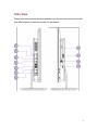
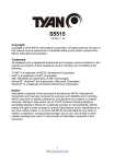
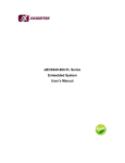
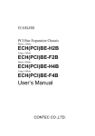
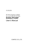
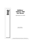
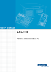
Maestro 880 Deluxe User Manual Ver20130708 To know Maestro 880 Front View Please refer below picture showing and take note the real front view and function may differ depend on what the model you purchased. 2 1 Webcam The Built-in webcam is 1.0M HD pixel with digital micro phone to allow your video with chats online. 2 LCD Display (Touch function enabled with optional item) This 23.6 inch LCD panel is LED type with high brightness and contrast appearance. The optimal resolution is 1920 x 1080, feature edge-to-edge touch function that enable ten-fingers-touch to enjoy your digital finger life. 3 Speakers High definition sound quality brings you to enjoy great music world. 4 Ambient light sensor This sensor could sense the user environment brightness to auto tune panel brightness. 3 Rear View Please refer below picture showing and take note the real rear view and function may differ depend on what the model you purchased. 4 1 Stand Adjustable stand help you to position the system upright. 2 Less screw design Two screws allows you open system easier. 3 ECO button Push ECO button to save earth with green concept. Short push this button will trigger your PC to be power saving mode. Long push this button will trigger your PC to be away mode. 4 HD Video in button Switch you PC to receive HD video with audio content. 5 HDD/ODD drive LED This LED indicates HDD/ODD drive activity. 6 Power ON/OFF button Power ON/OFF switch allow you turn on/off your PC. 5 Side View Please refer below picture showing and take note the real side view and function may differ depend on what the model you purchased. 6 1 Microphone jack This connector allows you connect a microphone. 2 Earphone/Audio jack This is 3.5mm jack to connect the system’s audio out signal to amplified speakers or headphones. While this jack connect to related device system will automatically disables the built-in speakers. 3 HD video input HD (High-Definition) inlet allows you input all digital audio/video interfaces between any video/audio source. 4 HD video output HD (High-Definition) output allows you connect to second monitor which display the digital HD audio/video content from Maestro all-in-one system. 5 USB port (Charging port enable with optional item) These USB (Universal Series Bus) ports allow you to use Keyboard, mouse, Hard drive….etc. If you purchase the charging port function it allow user to speed charge the handy device with charging port. 6 DC inlet The power adapter converts AC to DC for use with this DC inlet. To prevent damage please use supplied power adapter. 7 LAN port This RJ45 LAN port supports a standard Ethernet cable to connect network. 7 8 Brightness control The Brightness control allows you to tune the panel brightness to suit your personal request. 9 USB port These USB (Universal Series Bus) ports allow you to use Keyboard, mouse, Hard drive….etc. Card reader This AIO built in 4-in-1 card reader. SD/MMC/MS/MSPRO card type support. Optical drive This device may support you play DVD/CD disc and be recordable or re-writeable. 8 System Information 1. PRODUCT SPECIFICATION 1.1 INTRODUCTION This document describes a platform based on Intel Panther Point and relative devices’ Spec and function. This board supports Haswell CPU of TDP 65W, LGA1150 pins Processor from INTEL and 2 pcs DDRIII 800/1066/1333/1600 DIMMs (dual channel). The display is 23.6” LCD panel. This board provides a standard PC I/O offering – one Giga LAN, 4-in-1 card reader & USB connector. 1.2 STANDARD FEATURES Maestro 880 Motherboard Specification Model CPU Support CPU Intel Haswell Processor (support 65W) Socket LGA1150 Chipset System Memory Intel Panther Point H87 Consumer 2 DIMMS with Dual-Channel support (Max 16GB) DDR3 DIMM 800/1066/1333/1600 Non-ECC memory support BIOS AMI BIOS Super I/O ITE IT8519 embedded controller Graphic Sandy Bridge integrated Gfx with Transmitter on MB Shared main memory Audio ALC662-VD0-GR LAN 10/100/1000 Base-T Ethernet (Realtek RTL8111 ) Wireless LAN 802.11 b/g/n MiniCard (rev.1.2 support) BT 4.0/3.0 support 9 Model Maestro 880 Motherboard Specification TV PCIe x1 I/F TV Board Card Reader Support SD / MS / MS PRO / MMC USB3.0 By chip LCD 23.6” FHD (1920x1080) External I/O 1. LAN RJ45 2. DC inlet 3. HD in 4. HD out 5. 2 x USB2.0 6. 3 x USB3.0 7. 1 x USB3.0 with speed charging function 8. Mic in 9. Line out 10. 4-in-1 card reader 11. Brightness control Storage 3.5” /2.5” Desktop Type Serial-ATA I/F Optical Device Tray type ODD 10 1.3 MB PLACEMENT 11 2. DETAIL SPECIFICATION 2.1 SWITCH BUTTON Function PC power Power On/Off, go to S3/S4(follows the Windows Setting) HDMI mode Switch the display of screen from PC to HDMI input ECO/Away mode Decrease the frequency of CPU and turn the backlight down Brightness + The control switch for brightness of LCD monitor (10 steps) Brightness - The control switch for brightness of LCD monitor (10 steps) ODD Eject ODD tray eject/insert (It can be pushed when ODD tray is ejection) 2.2 LED CONDITIONS (1) Power LED status System State Power LED State and Color S0 Turn On (blue) S1 Slow Blink (blue) S2 S3 Slow Blink (blue) S4 Turn Off S5 Turn Off (2) Other LED status LED State LED name LED Color Turn On Condition HDD/ODD Blue access LED Turn Off Condition Under the not Dimmer mode, and Under the Dimmer mode, or when when system access to HDD or system doesn't access to HDD or ODD ODD. HDMI LED Blue In HDMI mode Out of HDMI mode ECO LED Blue Turn on the ECO mode Leave the ECO mode Amber Turn on the Away mode Leave the away mode 12 2.3 CONNECTORS / HEADERS Locn Physical Description SKTH_1 Socket 1155 sandy bridge J1 Function CPU socket TF-CON;HDR,3P*1,MA,2.54MM,ST,BLACK,TIN,DIP Clear CMOS 5P*2/-P9_2.54MM_ST/MA_Black Side IO header, 10 pin (USB) J3 HDMI_19P_MA_1.0MM_ST_BLACK HDMI Input J4 TF-CON;SATA,SBU,POWER,15P,MA,1.27MM,ST,2 Walls,BLACK,Gold Flash,LCP SATA power connector J5 40P_0.5MM_R/A_Buttom_contact LVDS connector J6 4P*1_1.25MM_MA_ST_BRASS/TIN_3A_LOCK_DIP Ambient Light Sensor header J7 1x3, 2.54mm pitch, unshrouded, red header backlight power select J8 8P*1/4 Wall_2.0mm_ST_White backlight power header J9 5P*2/-P9_BOX_MA_2.0MM_ST BIOS Tracker Header J10 RJ45,14P,FM,1PORT,R/A,BLACK,W/LED,GOLD 30U",GREEN/YELLOW,DIP LAN connector J11 15P*1_2GND NFC Connector J12 4P*1_FAN_2.5mm_ST_White/HTP CPU FAN J13 4P*1_FAN_2.5mm_ST_Red/HTP System FAN J14 SATA_7P_15"_Blue_W/LOCK SATA connector J15 SATA_7P_15"_Black_W/LOCK SATA connector J2 J16 1. USB3.0*2_2SLOT_BLUE_R/A 1. USB3.0 2 port (option) 2.USB,A,4P*2,2SLOTS,FM,BLACK,30U" Au,R/A,DIP 2.USB2.0 2 port J17 J18 J19 J20 1.0MM_MA_ST_GOLD_1A_16*2P_LOCK_SMT Rear IO connector (Mitac) POWER,SBU,ATX,DC/600V,2 A,2P,FM,4.2mm,ST Power Connector USB3.0*2_2SLOT_BLUE_R/A USB3.0 2 port (charging port) 6P*1_1.25MM_MA_ST_BRASS_TIN_3A_LOCK_DIP B-CAS connector 13 J21/J22 Mini_PCIE_52P_H9.0MM_3NUT Mini_PCIE J23 DC JACK,DC,10A,11P,FM,3.2MM,R/A,50uAu, DC Jack J24 AUDIO JACK_6P_pink_D3.5_R/A MIC in J26 AUDIO JACK_6P_green_D3.5_R/A Audio line out J27 1P*4_Box_2.00mm_Yellow speaker 5P*1_-P5_2.54mm_ST_BLACK Side IO Header 5 pin (USB) J30 20P_B/B_1.0MM_MA_ST_Gold_W/LOCK Front SW/LEDs (Mitac) J31 5P*1_-P5_2.54mm_ST_YELLOW DMIC header J32 5P*1_-P5_2.54mm_ST_BLACK Touch screen connector J33 20P_B/B_1.0MM_MA_ST_Gold_W/LOCK Side IO header (Mitac) J34 5P*2/-P10 FIO header (standard) J35 6P*1_B/B_1.25MM_ST_Gold Proximity Sensor header J36 5P*1_-P5_2.54mm_ST_BLACK Webcam header J39 5P*1_1.25MM_MA_ST_BRASS_TIN_3A_LOCK_DIP CIR header J28 14 BIOS Information 15 1. Main Page Main Advanced Chipset BIOS Information BIOS Vender Core Version Compliancy BIOS Version EC Version Build Date and Time Boot Security Save & Exit Item help American Megatrends 4.6.5.3 UEFI 2.3; PI 1.2 01A 01/20/2012 10:06:12 Processor Information Intel(R) Core(TM) i5-3550S CPU @ 3.00GHz SATA Devices Hard Disk Solid-State Disk DVD-ROM Empty Empty Empty →←: Select Screen ↑↓: Select Item Enter: Select +/- : Change Opt Memory Information Total Memory F1: General Help 16384 MB (DDR3 1333) F2: Previous Values F3: Optimized Defaults System Date System Time [Mon, mm/dd/yyyy] [hh:mm:ss] F4: Save & Reset ESC: Exit Version 2.14.1219. Copyright (C) 2011 American Megatrends, Inc. Field Name BIOS Vender Default Value AMI Megatrends Comment This field is not selectable. There is no help text associated with it. Field Name Core Version Default Value 4.6.5.1 Comment This field is not selectable. There is no help text associated with it. 16 Field Name Complacency Default Value UEFI 2.3; PI 1.2 Comment This field is not selectable. There is no help text associated with it. Field Name BIOS Version Default Value Display the version of the BIOS Comment This field is not selectable. There is no help text associated with it. Field Name EC Version Default Value Display the version of the EC Firmware Comment This field is not selectable. There is no help text associated with it. Field Name Build Date and Time Default Value Display build time of the BIOS Comment This field is not selectable. There is no help text associated with it. Field Name Processor Information Value Display the installed CPU brand. Comment This field is not selectable. There is no help text associated with it. Field Name Hard Disk Value Display the installed SATA port 1 devices. Comment This field is not selectable. There is no help text associated with it. Field Name Solid-State Disk Value Display the installed SSD devices. Comment This field is not selectable. There is no help text associated with it. Field Name DVD-ROM Value Display the installed SATA port 2 devices. Comment This field is not selectable. There is no help text associated with it. Field Name Total Memory Value Display the installed memory size. 17 Comment This field is not selectable. There is no help text associated with it. Field Name System Date Default Value [xxx, mm dd yyyy] Possible Value [xxx, xx:xx:xxxx] Help Changes the day, month, year and week. Field Name System Time Default Value [hh :mm :ss] Possible Value [xx :xx :xx] Help Changes the internal clock 18 2. Advanced Page Main Advanced Chipset Boot Security Save & Exit Item help Wireless RF Wake On Lan USB Charging Mode Motion Sensor Time To Turn Off Screen [Enabled] [Enabled] [Charging S3/S4/S5] [Disabled] 3 ►ACPI Settings →←: Select Screen ►S5 RTC Wake Settings ►Trusted Computing ►CPU Configuration ►Fan Speed Configuration ►SATA Configuration ►Intel Rapid Start Technology ►USB Configuration ↑↓: Select Item ►SMART Settings ►Network Stack ►CPU PPM Configuration ESC: Exit Enter: Select +/- : Change Opt F1: General Help F2: Previous Values F3: Optimized Defaults F4: Save & Reset ►RealTek PCIe GBE Family Controller Version 2.14.1219. Copyright (C) 2011 American Megatrends, Inc. Field Name Wireless RF Default Value [Enabled] Possible Value Enabled Disabled Help Enable or Disable Wireless RF switch. Field Name Wake On Lan Default Value [Enabled] Possible Value Enabled 19 Disabled Help Enable or Disable Wake On Lan. Field Name USB Charging Mode Default Value [Charging S3/S4/S5] Possible Value Disabled Charging S3/S4/S5 Charging Only Help Select USB port charging mode. Field Name Motion Sensor (M750 Only) Default Value [Disabled] Possible Value Enabled Disabled Help Enable or Disable Motion Sensor. Field Name Time To Turn Off Screen (Hided if Motion Sensor is Disabled) Default Value [3] Possible Value 1-255 Help Number of seconds to wait user to depart from PC, and it will turn off screen (From 1~255). Field Name ACPI Settings Help System ACPI Parameters. Comment Press Enter when selected to go into the associated Sub-Menu. Field Name S5 RTC Wake Settings Help Enable system to wake from S5 using RTC alarm Comment Press Enter when selected to go into the associated Sub-Menu. Field Name Trusted Computing Help Trusted Computing Settings Comment Press Enter when selected to go into the associated Sub-Menu. 20 Field Name CPU Configuration Help CPU Configuration Parameters Comment Press Enter when selected to go into the associated Sub-Menu. Field Name Fan Speed Configuration Help Fan Control Configuration. Comment Press Enter when selected to go into the associated Sub-Menu. Field Name SATA Configuration Help SATA Devices Options Settings. Comment Press Enter when selected to go into the associated Sub-Menu. Field Name Intel Rapid Start Technology Help Intel(R) Rapid Start Technology. Comment Press Enter when selected to go into the associated Sub-Menu. Field Name USB Configuration Help USB Configuration Parameters. Comment Press Enter when selected to go into the associated Sub-Menu. Field Name SMART Settings Help System SMART Settings. Comment Press Enter when selected to go into the associated Sub-Menu. Field Name Network stack Help Network stack Settings. Comment Press Enter when selected to go into the associated Sub-Menu. Field Name CPU PPM Configuration Help CPU PPM Configuration Parameters. Comment Press Enter when selected to go into the associated Sub-Menu. Field Name RealTek PCIe GBE Family Controller (MAC:00:22:4D:7F:87:60) 21 Help Get driver information and configure Realtek Ethernet controller parameter. Comment Press Enter when selected to go into the associated Sub-Menu. 22 2.1 ACPI Settings Main Advanced Chipset Boot Security Save & Exit Item help ACPI Settings Enable ACPI Auto Configuration [Disabled] Enable Hibernation ACPI Sleep State [Enabled] [S3 only(Suspend to RAM)] →←: Select Screen ↑↓: Select Item Enter: Select +/- : Change Opt F1: General Help F2: Previous Values F3: Optimized Defaults F4: Save & Reset ESC: Exit Version 2.02.1205. Copyright (C) 2010 American Megatrends, Inc. Field Name Enable ACPI Auto Configuration Default Value [Disabled] Possible Value Enabled Disabled Help Enables or Disables BIOS ACPI Auto Configuration. Field Name Enable Hibernation Default Value [Enabled] Possible Value Enabled Disabled Help Enables or Disables System ability to Hibernate (OS/S4 Sleep State). This option may be not effective with some OS. Field Name ACPI Sleep State Default Value [S3 (Suspend to RAM)] 23 Possible Value Suspend Disabled S1 only(CPU Stop Clock) S3 only(Suspend to RAM) Help Select ACPI sleep state the system will enter when the SUSPEND button is pressed. 24 2.2 S5 RTC Wake Settings Main Advanced Chipset Boot Security Wake system with Fixed Time Wake up hour Wake up minute Wake up second Save & Exit Item help [Disabled] 0 0 0 →←: Select Screen ↑↓: Select Item Enter: Select +/- : Change Opt F1: General Help F2: Previous Values F3: Optimized Defaults F4: Save & Reset ESC: Exit Version 2.14.1219. Copyright (C) 2011 American Megatrends, Inc. Field Name Wake system with Fixed Time Default Value [Disabled] Possible Value Enabled Disabled Help Enable or Disable System wake on alarm event. When enabled, System will wake on the hr::min::sec specified Field Name Wake up hour Default Value 0 Possible Value 0-23 Help Select 0-23 For example enter 3 for 3am and 15 for 3pm Field Name Wake up minute Default Value 0 25 Possible Value 0-59 Help 0 - 59 Field Name Wake up second Default Value 0 Possible Value 0 - 59 Help 0 - 59 26 2.3 Trusted Computing Main Advanced Chipset Boot Security Save & Exit Item help Configuration Security Device Support TPM State Pending operation [Enable] [Enabled] [None] →←: Select Screen Current Status Information TPM Enabled Status: TPM Active Status: [Enabled] [Activated] ↑↓: Select Item TPM Owner Status: [Unowned] +/- : Change Opt Enter: Select F1: General Help F2: Previous Values F3: Optimized Defaults F4: Save & Reset ESC: Exit Version 2.14.1219. Copyright (C) 2011 American Megatrends, Inc. Field Name Security Device SUPPORT Default Value [Enable] Possible Value Enable Disable Help Enables or Disables BIOS support for security device. O.S. will not show Security Device. TCG EFI protocol and INT1A interface will not be available. Field Name TPM State Default Value [Enabled] Possible Value Enabled Disabled Help Enable/Disable Security Device. NOTE: Your Computer will reboot during restart in order to change State of the Device. 27 Field Name Pending operation Default Value [None] Possible Value None TPM Clear Help Schedule an Operation for the Security Device. NOTE: Your Computer will reboot during restart in order to change State of Security Device. Field Name TPM Enabled Status: Default Value [Enabled] Comment This field is not selectable. There is no help text associated with it. Field Name TPM Active Status: Default Value [Activated] Comment This field is not selectable. There is no help text associated with it. Field Name TPM Owner Status: Default Value [Unowned] Comment This field is not selectable. There is no help text associated with it. 28 2.4 CPU Configuration Main Advanced Chipset Boot Security Save & Exit Item help CPU Configuration Intel(R) Core(TM) CPU [CPU NAME] @ [CPU Freq.] GHz CPU Signature 306a9 Microcode Patch 12 Max CPU Speed 3000 MHz Min CPU Speed 1600 MHz CPU Speed Processor Cores Intel HT Technology Intel VT-x Technology Intel SMX Technology 64-bit 3000 MHz 4 Supported Supported Supported Supported L1 Data Cache L1 Code Cache 32 KB x 4 32 KB x 4 L2 Cache L3 Cache 256 KB x 4 6144 KB →←: Select Screen Hyper-threading Active Processor Cores Limit CPUID Maximum Intel Virtualization Technology Hardware Prefetcher Adjacent Cache Line Prefetch [Enabled] [All] [Disabled] [Disabled] [Enabled] [Enabled] ↑↓: Select Item Enter: Select +/- : Change Opt F1: General Help F2: Previous Values F3: Optimized Defaults F4: Save & Reset ESC: Exit Version 2.14.1219. Copyright (C) 2011 American Megatrends, Inc. Field Name CPU Configuration Default Value [Intel CPU Brand String] Comment This field is not selectable. There is no help text associated with it. 29 Field Name CPU Signature Default Value Displays CPU Signature Comment This field is not selectable. There is no help text associated with it. Field Name Microcode Patch Default Value CPU Microcode Patch Revision Comment This field is not selectable. There is no help text associated with it. Field Name Max CPU Speed Default Value Displays the Max CPU Speed Comment This field is not selectable. There is no help text associated with it. Field Name Min CPU Speed Default Value Displays the Min CPU Speed Comment This field is not selectable. There is no help text associated with it. Field Name CPU Speed Default Value Displays the CPU Speed Comment This field is not selectable. There is no help text associated with it. Field Name Processor Cores Default Value Displays number of cores. Comment This field is not selectable. There is no help text associated with it. Field Name Intel HT Technology Default Value When Hyper-threading is enabled, 2 logical CPUS per core is present. Comment This field is not selectable. There is no help text associated with it. Field Name Intel VT-x Technology Default Value CPU VMX hardware support for virtual machines. Comment This field is not selectable. There is no help text associated with it. Field Name Intel SMX Technology 30 Default Value Secure Mode extensions support. Comment This field is not selectable. There is no help text associated with it. Field Name 64-bit Default Value Displays if 64-bit supported Comment This field is not selectable. There is no help text associated with it. Field Name L1 Data Cache Default Value L1 Data Cache Size Comment This field is not selectable. There is no help text associated with it. Field Name L1 Code Cache Default Value L1 Code Cache Size Comment This field is not selectable. There is no help text associated with it. Field Name L2 Cache Default Value L2 Cache Size Comment This field is not selectable. There is no help text associated with it. Field Name L3 Cache Default Value L3 Cache Size Comment This field is not selectable. There is no help text associated with it. Field Name Hyper-threading (Hided if HT not Supported) Default Value [Enabled] Possible Value Enabled Disabled Help Enabled for Windows XP and Linux (OS optimized for Hyper-Threading Technology) and Disabled for other OS (OS not optimized for Hyper-Threading Technology). When Disable only one thread per enabled core is enabled. 31 Field Name Active Processor Cores Default Value [All] Possible Value All 1/2/3/4/5/6/7/8 Help Number of cores to enable in each processor package. Field Name Limit CPUID Maximum Default Value [Disabled] Possible Value Enabled Disabled Help Disabled for Windows XP Field Name Intel Virtualization Technology Default Value [Enabled] Possible Value Enabled Disabled Help When enabled, a VMM can utilize the additional hardware capabilities provided by Vanderpool Technology Field Name Hardware Prefetcher Default Value [Enabled] Possible Value Enabled Disabled Help To turn on/off the Mid Level Cache (L2) streamer prefetcher. Field Name Adjacent Cache Line Prefetch Default Value [Enabled] Possible Value Enabled Disabled Help To turn on/off prefetching of adjacent cache lines. 32 2.5 Fan Speed Configuration Main Advanced Chipset Boot Security Save & Exit Item help Fan Speed Configuration Fan Speed Control CPU Fan Speed [Auto] [Normal] →←: Select Screen ↑↓: Select Item Enter: Select +/- : Change Opt F1: General Help F2: Previous Values F3: Optimized Defaults F4: Save & Reset ESC: Exit Version 2.14.1219. Copyright (C) 2011 American Megatrends, Inc. Field Name Fan Speed Control Default Value [Auto] Possible Value Auto / Manual Help Set Fan Speed mode. Attention: Select Manual Silent or Normal mode may be NOT cooling system enough. Comment Field Name CPU Fan Speed Default Value [Normal] Possible Value Silent / Normal / Optimize Help Adjust CPU Fan Speed PWM Duty. Comment 33 2.6 SATA Configuration Main Advanced Chipset Boot Security Save & Exit Item help SATA Mode Selection SATA Controller Speed [AHCI] [Gen3] Serial ATA Port 0 Serial ATA Port 1 Serial ATA Port 2 Empty Empty Empty →←: Select Screen ↑↓: Select Item Enter: Select +/- : Change Opt F1: General Help F2: Previous Values F3: Optimized Defaults F4: Save & Reset ESC: Exit Version 2.14.1219. Copyright (C) 2011 American Megatrends, Inc. Field Name SATA Mode Selection Default Value [AHCI] Possible Value IDE / AHCI Help Determines how SATA controller(s) operate. Field Name SATA Controller Speed Default Value [Gen3] Possible Value Gen1 / Gen2 / Gen3 Help Indicates the maximum speed the SATA controller can support. Field Name Serial ATA Port 0 Default Value Empty Possible Value SATA Device Model Name 34 Field Name Serial ATA Port 1 Default Value Empty Possible Value SATA Device Model Name Field Name Serial ATA Port 2 Default Value Empty Possible Value SATA Device Model Name 35 2.7 Intel® Rapid Start Technology Main Advanced Chipset Boot Security Save & Exit Intel(R) Rapid Start Technology [Disabled] No valid iFFS partition found. Entry on S3 RTC Wake Entry After Active Page Threshold Support [Disabled] [10 minutes] [Disabled] Item help →←: Select Screen ↑↓: Select Item Enter: Select +/- : Change Opt F1: General Help F2: Previous Values F3: Optimized Defaults F4: Save & Reset ESC: Exit Version 2.14.1219. Copyright (C) 2011 American Megatrends, Inc. Field Name Intel(R) Rapid Start Technology Default Value [Disabled] Possible Value Disabled Enabled Help Enable or disable Intel(R) Rapid Start Technology. Field Name Entry on S3 RTC Wake Default Value [Disabled] Possible Value Disabled Enabled Help iFFS invocation upon S3 RTC wake. Field Name Entry After Default Value [10 minutes] Possible Value Immediately / 1 minute / 2 minutes / 5 minutes / 10 minutes / 15 minutes / 30 minutes / 1 hour / 2 hours 36 Help Enable RTC wake timer at S3 entry. Field Name Active Page Threshold Support Default Value [Disabled] Possible Value Disabled Enabled Help Support RST with small prtiotion. 37 2.8 USB Configuration Main Advanced Chipset Boot Security Save & Exit Item help USB Configuration USB Devices: 1 Keyboard, 1 Mouse, 2 Hubs Legacy USB Support USB3.0 Support [Enabled] [Enabled] →←: Select Screen XHCI Hand-off EHCI Hand-off [Enabled] [Disabled] Enter: Select Port 60/64 Emulation [Enabled] F1: General Help ↑↓: Select Item +/- : Change Opt F2: Previous Values F3: Optimized Defaults F4: Save & Reset ESC: Exit Version 2.14.1219. Copyright (C) 2011 American Megatrends, Inc. Field Name USB Devices: Default Value Connected USB devices Comment This field is not selectable. There is no help text associated with it. Field Name Legacy USB Support Default Value [Enabled] Possible Value Disabled Enabled Auto Help Enables Legacy USB support. AUTO option disables legacy support if no USB devices are connected. DISABLE option will keep USB devices available only for EFI applications. Field Name USB3.0 Support Default Value [Enabled] Possible Value Disabled Enabled 38 Help Enable/Disable USB3.0 (XHCI) Controller support. Field Name XHCI Hand-off Default Value [Enabled] Possible Value Disabled Enabled Help This is a workaround for OSes without XHCI hand-off support. The XHCI ownership change should be claimed by XHCI driver. Field Name EHCI Hand-off Default Value [Disabled] Possible Value Disabled Enabled Help This is a workaround for OSes without EHCI hand-off support. The EHCI ownership change should be claimed by EHCI driver. Field Name Port 60/64 Emulation Default Value [Disabled] Possible Value Disabled Enabled Help Enables I/O port 60h/64h emulation support. This should be enabled for the complete USB keyboard legacy support for non-USB aware OSes. 39 2.9 SMART Settings Main Advanced Chipset Boot Security Save & Exit Item help SMART Settings SMART Self Test [Disabled] →←: Select Screen ↑↓: Select Item Enter: Select +/- : Change Opt F1: General Help F2: Previous Values F3: Optimized Defaults F4: Save & Reset ESC: Exit Version 2.14.1219. Copyright (C) 2011 American Megatrends, Inc. Field Name SMART Self Test Default Value [Disabled] Possible Value Disabled Enabled Help Run SMART Self Test on all HDDs during POST. 40 2.10 Network Stack Main Advanced Chipset Boot Security Save & Exit Item help Network stack Ipv4 PXE Support Ipv6 PXE Support [Enabled] [Enabled] [Enabled] →←: Select Screen ↑↓: Select Item Enter: Select +/- : Change Opt F1: General Help F2: Previous Values F3: Optimized Defaults F4: Save & Reset ESC: Exit Version 2.14.1219. Copyright (C) 2011 American Megatrends, Inc. Field Name Network stack Default Value [Enabled] Possible Value Disabled Enabled Help Enable/Disable UEFI network stack. Field Name Ipv4 PXE Support Default Value [Enabled] Possible Value Disabled Enabled Help Enable Ipv4 PXE Boot Support. If disabled IPV4 PXE boot option will not be created. Field Name Ipv6 PXE Support Default Value [Enabled] Possible Value Disabled Enabled 41 Help Enable Ipv6 PXE Boot Support. If disabled IPV4 PXE boot option will not be created. 42 2.11 CPU PPM Configuration Main Advanced Chipset Boot Security Save & Exit Item help CPU PPM Configuration EIST Turbo Mode CPU C3 Report CPU C6 Report [Enabled] [Enabled] [Enabled] [Enabled] →←: Select Screen ↑↓: Select Item Enter: Select +/- : Change Opt F1: General Help F2: Previous Values F3: Optimized Defaults F4: Save & Reset ESC: Exit Version 2.14.1219. Copyright (C) 2011 American Megatrends, Inc. Field Name EIST Default Value [Enabled] Possible Value Disabled Enabled Help Enable/Disable Intel SpeedStep. Field Name Turbo Mode Default Value [Enabled] Possible Value Disabled Enabled Help Turbo Mode. Field Name CPU C3 Report Default Value [Enabled] Possible Value Disabled 43 Enabled Help Enable/Disable CPU C3(ACPI C2) report to OS Field Name CPU C6 Report Default Value [Enabled] Possible Value Disabled Enabled Help Enable/Disable CPU C6(ACPI C3) report to OS 44 2.12 Realtek PCIe GBE Family Controller (If Network Stack IPv4/IPv6 enabled, create by RealTek UEFI PXE Driver) Main Advanced Chipset Driver Information Driver Name: Driver Version Driver Release Date: Boot Security Save & Exit Item help Realtek UEFI UNDI Driver 2.011 2012/07/23 Device Information Device Name: PCI Slot: MAC Address: Realtek PCIe GBE Family Controller 02:00:00 (as user system) →←: Select Screen ↑↓: Select Item Enter: Select +/- : Change Opt Advanced Settings Link Speed & Duplex F1: General Help [Auto Negotiation] F2: Previous Values F3: Optimized Defaults F4: Save & Reset ESC: Exit Version 2.14.1219. Copyright (C) 2011 American Megatrends, Inc. Field Name Driver Name: Default Value Installed UEFI Driver Name Comment This field is not selectable. There is no help text associated with it. Field Name Driver Version: Default Value Installed UEFI Driver Version Comment This field is not selectable. There is no help text associated with it. Field Name Driver Release Date: Default Value Installed UEFI Driver Release Date Comment This field is not selectable. There is no help text associated with it. Field Name Device Name: Default Value UEFI driver support device 45 Comment This field is not selectable. There is no help text associated with it. Field Name PCI Slot: Default Value Device PCI Bus/Device/Number Comment This field is not selectable. There is no help text associated with it. Field Name MAC Address: Default Value LAN Device Mac address Comment This field is not selectable. There is no help text associated with it. Field Name Link Speed & Duplex Default Value [Auto Negotiation] Possible Value Auto Negotiation / 10 Mpbs HALF Duplex / 10 Mpbs Full Duplex / 100 Mpbs Half Duplex / 100 Mpbs Full Duplex 1.0 Gbps Full Duplex Help Change link speed and duplex for current adapter. 46 3. Chipset Main Advanced Chipset Boot Security Save & Exit ►PCH-IO Configuration ►System Agent (SA) Configuration Item help →←: Select Screen ↑↓: Select Item Enter: Select +/- : Change Opt F1: General Help F2: Previous Values F3: Optimized Defaults F4: Save & Reset ESC: Exit Version 2.14.1219. Copyright (C) 2011 American Megatrends, Inc. Field Name PCH-IO Configuration Help PCH Parameters Comment Press Enter when selected to go into the associated Sub-Menu. Field Name System Agent (SA) Configuration Help System Agent (SA) Parameters Comment Press Enter when selected to go into the associated Sub-Menu. 47 3.1 PCH-IO Configuration Main Advanced Chipset Boot Security Save & Exit Item help LAN Controller DeepSx Power Policies Restore AC Power Loss [Enabled] [Disabled] [Power Off] →←: Select Screen ↑↓: Select Item Enter: Select +/- : Change Opt F1: General Help F2: Previous Values F3: Optimized Defaults F4: Save & Reset ESC: Exit Version 2.14.1219. Copyright (C) 2011 American Megatrends, Inc. Field Name LAN Controller Default Value [Enabled] Possible Value Enabled Disabled Help Enable or disable onboard NIC. Field Name DeepSx Power Policies Default Value [Disabled] Possible Value Disabled Enabled in S4-S5 Help Configure the DeepSx Mode configuration. Field Name Restore AC Power Loss Default Value [Power Off] Possible Value Power Off Power On Last State Help Select AC power state when power is re-applied after a power 48 failure. 49 3.2 System Agent (SA) Configuration Main Advanced Chipset Boot Security Save & Exit Item help ►Graphics Configuration ►Memory Configuration →←: Select Screen ↑↓: Select Item Enter: Select +/- : Change Opt F1: General Help F2: Previous Values F3: Optimized Defaults F4: Save & Reset ESC: Exit Version 2.14.1219. Copyright (C) 2011 American Megatrends, Inc. Field Name Graphics Configuration Help Config Graphics Settings. Comment Press Enter when selected to go into the associated Sub-Menu. Field Name Memory Configuration Help Memory Configuration Parameters Comment Press Enter when selected to go into the associated Sub-Menu. 50 3.2.1 Graphics Configuration Main Advanced Chipset Boot Security Save & Exit Item help Graphics Configuration IGFX VBIOS Version N/A DVMT Pre-Allocated [64M] DVMT Total Gfx Mem [256M] →←: Select Screen ↑↓: Select Item Enter: Select +/- : Change Opt F1: General Help F2: Previous Values F3: Optimized Defaults F4: Save & Reset ESC: Exit Version 2.14.1219. Copyright (C) 2011 American Megatrends, Inc. Field Name IGFX VBIOS Version Default Value IGFX VBIOS Version (UEFI GOP Mode: NA) Comment This field is not selectable. There is no help text associated with it. Field Name DVMT Pre-Allocated Default Value [64M] Possible Value 32M / 64M / 96M / 128M / 160M / 192M / 224M / 256M / 288M / 320M / 352M / 384M / 416M / 448M / 480M / 512M / 1024M Help Select DVMT 5.0 Pre-Allocated (Fixed) Graphics Memory size used by the Internal Graphics Device. Field Name 4 Default Value [256M] Possible Value 128MB / 256MB / MAZ Help Select DVMT5.0 Total Graphic Memory size used by the Internal DVMT Total Gfx Mem Graphics Device. 51 3.2.2 Memory Configuration Main Advanced Chipset Boot Security Save & Exit Item help Memory Information Memory Frequency Total Memory DIMM#0 DIMM#1 1333 Mhz 16384 MB (DDR3 1333) 8192 MB (DDR3 1333) 8192 MB (DDR3 1333) CAS Latency (tCL) Minimum delay time CAS to RAS (tRCDmin) Row Precharge (tRPmin) Active to Precharge (tRASmin) Memory Frequency Limiter 9 9 9 24 [Auto] →←: Select Screen ↑↓: Select Item Enter: Select +/- : Change Opt F1: General Help F2: Previous Values F3: Optimized Defaults F4: Save & Reset ESC: Exit Version 2.14.1219. Copyright (C) 2011 American Megatrends, Inc. Field Name Memory Frequency Default Value Show Memory Frequency. Comment This field is not selectable. There is no help text associated with it. Field Name Total Memory Default Value Total Memory in the System. Comment This field is not selectable. There is no help text associated with it. 52 Field Name DIMM#0 Default Value Memory in the DIMM. Comment This field is not selectable. There is no help text associated with it. Field Name DIMM#1 Default Value Memory in the DIMM. Comment This field is not selectable. There is no help text associated with it. Field Name CAS Latency (tCL) Default Value tCL value Comment This field is not selectable. There is no help text associated with it. Field Name CAS to RAS (tRCDmin) Default Value tRCD value Comment This field is not selectable. There is no help text associated with it. Field Name Row Precharge (tRPmin) Default Value tRP value Comment This field is not selectable. There is no help text associated with it. Field Name Active to Precharge (tRASmin) Default Value tRAS value Comment This field is not selectable. There is no help text associated with it. Field Name Memory Frequency Limiter Default Value [Auto] Possible Value Auto / 1067 / 1333 / 1600 / 1867 / 2133 / 2400 /2667 Help Maximum Memory Frequency Selections in Mhz. The purpose is not for over-clocking but downgrading Memory performance by frequency limiter. 53 4. Boot Main Advanced Chipset Boot Security Save & Exit Item help Boot Configuration Setup Prompt Timeout Bootup NumLock State 1 [On] Full Screen Logo Fast Boot [Enabled] [Disabled] Boot mode select [UEFI] FIXED BOOT ORDER Priorities Boot Option #1 Boot Option #2 Boot Option #3 Boot Option #4 Boot Option #5 Boot Option #6 Boot Option #7 [CD/DVD] [Hard Disk] [Network] [USB CD/DVD] [USB Hard Disk] [USB KEY] [USB Floppy] →←: Select Screen ↑↓: Select Item Enter: Select ►CSM parameters +/- : Change Opt F1: General Help CD/DVD ROM Drive BBS Priorities Hard Disk Drive BBS Priorities USB KEY Drive BBS Priorities F2: Previous Values F3: Optimized Defaults F4: Save & Reset ESC: Exit Version 2.14.1219. Copyright (C) 2011 American Megatrends, Inc. Field Name Setup Prompt Timeout Default Value 1 Possible Value 1~65535 Help Number of seconds to wait for setup activation key. 65535(0xFFFF) means indefinite waiting. 54 Field Name Boot NumLock State Default Value [On] Possible Value On Off Help Select the keyboard NumLock state Field Name Full Screen Logo Default Value [Enabled] Possible Value Enabled Disabled Help Enables or disables Full Screen Logo option Field Name Fast Boot Default Value [Disabled] Possible Value Enabled Disabled Help Enables or disables boot with initialization of a minimal set of devices required to launch active boot option. Has no effect for BBS boot options. Field Name Boot mode select Default Value [UEFI] Possible Value LEGACY UEFI Help Select boot mode LEGACY/UEFI. Field Name Boot Option #1 Default Value [CD/DVD] Possible Value CD/DVD, Hard Disk, Network, USB CD/DVD, USB Hard Disk, USB KEY, USB Floppy, UEFI Help Set boot Priority 55 Field Name Boot Option #2 Default Value [Hard Disk] Possible Value CD/DVD, Hard Disk, Network, USB CD/DVD, USB Hard Disk, USB KEY, USB Floppy, UEFI Help Set boot Priority Field Name Boot Option #3 Default Value [Network] Possible Value CD/DVD, Hard Disk, Network, USB CD/DVD, USB Hard Disk, USB KEY, USB Floppy, UEFI Help Set boot Priority Field Name Boot Option #4 Default Value [USB CD/DVD] Possible Value CD/DVD, Hard Disk, Network, USB CD/DVD, USB Hard Disk, USB KEY, USB Floppy, UEFI Help Set boot Priority Field Name Boot Option #5 Default Value [USB Hard Disk] Possible Value CD/DVD, Hard Disk, Network, USB CD/DVD, USB Hard Disk, USB KEY, USB Floppy, UEFI Help Set boot Priority Field Name Boot Option #6 Default Value [USB KEY] Possible Value CD/DVD, Hard Disk, Network, USB CD/DVD, USB Hard Disk, USB KEY, USB Floppy, UEFI Help Set boot Priority Field Name Boot Option #7 (UEFI Boot Mode Not Support) Default Value [USB Floppy] Possible Value CD/DVD, Hard Disk, Network, USB CD/DVD, USB Hard Disk, USB KEY, USB Floppy, UEFI 56 Help Set boot Priority Field Name CSM parameters Help OpROM execution, boot options filter, etc. Comment Press Enter when selected to go into the associated Sub-Menu. Field Name CD/DVD ROM Drive BBS Priorities Help Specifies the Boot Device Priority sequence from available CDROM/DVD Drives. Comment Press Enter when selected to go into the associated Sub-Menu. Field Name Hard Disk Drive BBS Priorities Help Specifies the Boot Device Priority sequence from available Hard Disk Drives. Comment Press Enter when selected to go into the associated Sub-Menu. Field Name NETWORK Drive BBS Priorities Help Specifies the Boot Device Priority sequence from available NETWORK Drives. Comment Press Enter when selected to go into the associated Sub-Menu. Field Name USB CD/DVD ROM Drive BBS Priorities Help Specifies the Boot Device Priority sequence from available USB CDROM/DVD Drives. Comment Press Enter when selected to go into the associated Sub-Menu. Field Name USB Hard Disk Drive BBS Priorities Help Specifies the Boot Device Priority sequence from available USB Hard Disk Drives. Comment Press Enter when selected to go into the associated Sub-Menu. Field Name USB KEY Drive BBS Priorities Help Specifies the Boot Device Priority sequence from available USB 57 Key Drives. Comment Press Enter when selected to go into the associated Sub-Menu. Field Name USB Floppy Drive BBS Priorities (UEFI Boot Mode Not Support) Help Specifies the Boot Device Priority sequence from available USB Floppy Drives. Comment Press Enter when selected to go into the associated Sub-Menu. 58 4.1 CSM parameters Main Advanced Chipset Boot Security Save & Exit Item help Launch CSM Launch PXE OpROM policy Launch Video OpROM policy [Disabled] [Do not launch] [UEFI only] →←: Select Screen ↑↓: Select Item Enter: Select +/- : Change Opt F1: General Help F2: Previous Values F3: Optimized Defaults F4: Save & Reset ESC: Exit Version 2.14.1219. Copyright (C) 2011 American Megatrends, Inc. Field Name Launch CSM Default Value [Disabled] Possible Value Enabled Disabled Help This option controls if CSM will be launched. Field Name Launch PXE OpROM policy Default Value [Do not launch] Possible Value Do not launch UEFI only Legacy only Help Controls the execution of UEFI and Legacy PXE OpROM. Field Name Launch Video OpROM policy Default Value [UEFI only] Possible Value UEFI only Legacy only Help Controls the execution of UEFI and Legacy Video OpROM. 59 5 Security Main Advanced Chipset Boot Security Save & Exit Item help Password Description If the Administrator's password is set then limits access to Setup and is only asked for when entering Setup. The password length must be →←: Select Screen in the following range: Minimum Length ↑↓: Select Item 3 Enter: Select Maximum Length 20 +/- : Change Opt F1: General Help Administrator Password F2: Previous Values F3: Optimized Defaults System Mode state Secure Boot Mode Setup Disabled Secure Boot Secure Boot Mode ►Key Management F4: Save & Reset ESC: Exit [Disabled] [Standard] Version 2.14.1219. Copyright (C) 2011 American Megatrends, Inc. Field Name Administrator Password Help Set Setup Administrator Password Comment Press Enter when selected to go into the associated Sub-Menu. Field Name Secure Boot Default Value [Enabled] Possible Value Enabled Disabled Help Secure Boot flow control. Secure Boot is possible only if System runs in User Mode. 60 Field Name Secure Boot Mode Default Value [Standard] Possible Value Standard Custom Help Secure Boot mode selector. 'Standard' - fixed Secure boot policy, 'Custom' - changeable Image Execution policy and Secure Boot Key databases. Field Name Key Management Help Key Management Page, allows for manual modification of the content of the Secure Boot variables. Comment Press Enter when selected to go into the associated Sub-Menu. 61 6 Save & Exit Main Advanced Chipset Boot Security Save & Exit Item help Save Options Discard Changes and Exit Save Changes and Reset Discard Changes and Reset Restore Defaults Save as user Defaults Restore user Defaults Boot Override →←: Select Screen ↑↓: Select Item Enter: Select +/- : Change Opt F1: General Help F2: Previous Values F3: Optimized Defaults F4: Save & Reset ESC: Exit Version 2.14.1219. Copyright (C) 2011 American Megatrends, Inc. Field Name Discard Changes and Exit Help Exit system setup without saving any changes. Comment Field Name Save Changes and Reset Help Reset the system after saving the changes. Comment Field Name Discard Changes and Reset 62 Help Reset system setup without saving any changes. Comment Field Name Restore Defaults Help Restore/Load Default values for all the setup options. Comment Field Name Save as user Defaults Help Save the changes done so far as User Defaults. Comment Field Name Restore user Defaults Help Restore the User Defaults to all the setup options. Comment 63