1
NX242 Digital TDcontroller
ENGLISH
PAGE 2
IMPORTANT SAFETY INSTRUCTIONS
Declaration of conformity
This equipment has been tested and found to comply with the safety objectives and essential requirements of European (73/23/EEC and
89/336/EEC directives) and international Standards, by fulfilling the requirements of the following harmonized standards:
Electrical Safety (EU) : IEC 60065 (12/2001) Audio, video and similar electronic apparatus
Electrical Safety (US) : UL60065 Seventh Edition, dated June 30, 2003 category AZSQ, E241312.
Electrical Safety (CAN) : CSA-C22.2 N°60065:03 Edition, dated April 2003 category AZSQ7, E241312
Electrical Safety (Rest of the World) : CB test certificate DK-8371 based on IEC60065-2001 7nd ed. with all national deviations.
Radiated Emission (EU) : EN55103-1 (1996) Electromagnetic compatibility - Product family standard for audio, video, audiovisual and entertainment lighting control apparatus for professional use.
Audio Equipment
Radiated Emission (US) : FFC part15 class B
10CE
Radiated Emission (CAN) : This Class B digital apparatus complies with Canadian ICES-003.
RF Immunity (EU) : EN55103-2 (1996) Electromagnetic compatibility - Product family standard for audio, video, audio-visual and
entertainment lighting control apparatus for professional use.
Note: EMC conformance testing is based on the use of recommended cable types. The use of other cable types may degrade EMC
performances.
IMPORTANT SAFETY INSTRUCTIONS
1) Read these instructions.
2) Keep these instructions.
3) Heed all warnings.
4) Follow all instructions.
5) Do not use this apparatus near water.
6) Clean only with dry cloth.
7) Do not block any ventilation openings. Install in accordance with the
manufacturer’s instructions.
8) Do not install near any heat sources such as radiators, heat registers,
stoves, or other apparatus (including amplifiers) that produce heat.
9) Do not defeat the safety purpose of the polarized or grounding-type plug. A
polarized plug has two blades with one wider than the other. A grounding type
plug has two blades and a third grounding prong. The wide blade or the third
prong are provided for your safety. If the provided plug does not fit into your
outlet, consult an electrician for replacement of the obsolete outlet. (US
market)
10) Protect the power cord from being walked on or pinched particularly at
plugs, convenience receptacles, and the point where they exit from the
apparatus.
11) Only use attachments/accessories specified by the manufacturer.
13) Unplug this apparatus during lightning storms or when unused for long
periods of time.
14) Refer all servicing to qualified service personnel. Servicing is required
when the apparatus has been damaged in any way, such as power-supply
cord or plug is damaged, liquid has been spilled or objects have fallen into the
apparatus, the apparatus has been exposed to rain or moisture, does not
operate normally, or has been dropped.
Information about products that generate electrical noise :
NOTE: The United States Federal Communications Commission (in 47 CFR
15.105) has specified that the following notice be brought to the attention of
users of this product:
This equipment has been tested and found to comply with the limits for a
Class B digital device, pursuant to Part 15 of the FCC Rules. These limits are
designed to provide reasonable protection against harmful interference in a
residential installation. This equipment generates, uses and can radiate radio
frequency energy and, if not installed and used in accordance with the
instructions, may cause harmful interference to radio communications.
However, there is no guarantee that interference will not occur in a particular
installation. If this equipment does cause harmful interference to radio or
television reception, which can be determined by turning the equipment off
and on, the user is encouraged to try to correct the interference by one or
more of the following measures:
- Reorient or relocate the receiving antenna.
- Increase the separation between the equipment and receiver.
- Connect the equipment into an outlet on a circuit different from that to which
the receiver is connected.
- Consult the dealer or an experienced radio/TV technician for help.
The user may find the following booklet, prepared by the Federal
Communications Commission, helpful: How to identify and Resolve Radio/TV
Interference Problems. This booklet is available from the U.S. Government
Printing Office, Washington, D.C. 20402, Stock No. 004-000-00345-4. Use of
a shielded cable is required to comply within Class B limits of Part 15 of FCC
Rules. Pursuant to Part 15.21 of the FCC Rules, any changes or
modifications to this equipment not expressly approved by NEXO S.A. may
cause, harmful interference and void the FCC authorization to operate this
equipment.
CAUTION
RISK OF ELECTRIC SHOCK
DO NOT OPEN
The lightning flash with arrowhead
symbol, within an equilateral triangle
is intended to alert the user to the
presence of uninsulated “dangerous
voltage” within the product's
enclosure that may be of sufficient
magnitude to constitute a risk of
electric shock to persons.
WARNING: To reduce the risk of fire or electric shock,
do not expose this apparatus to rain or moisture.
To avoid electrical shock, do not remove covers.
Dangerous voltages exist inside.
Refer all servicing to qualified personnel only.
The exclamation point within an
equilateral triangle is intended to
alert the user to the presence of
important operating and
maintenance (servicing) instructions
in the literature accompanying
the appliance.
WARNING ! This appliance is a CLASS 1 apparatus and must be earthed.
The green and yellow wire of the mains cord must always be connected to an installation safety earth or ground. The earth is essential for
personal safety as well as the correct operation of the system, and is internally connected to all exposed metal surfaces. Additional
recommendation for interconnection to other equipment can be found in the “Setting-Up Advice” section page 8.
NX242 USER MANUAL LOAD2_22
DATE : 12/9/2004
INSTRUCTIONS DE SECURITE IMPORTANTES
Déclaration de conformité
Cet équipement a été testé et répond aux objectifs de sécurité et exigences essentielles de la directive 73/23/EEC sur les basses tensions et la
directive 89/336 EEC sur la compatibilité électromagnétique, notamment:
Sécurité électrique (EU) : IEC 60065 (12/2001) Appareils audio, vidéo et appareils électroniques analogues - Exigences de sécurité
Sécurité électrique (US) : UL60065 Seventh Edition, dated June 30, 2003 category AZSQ, E241312.
Sécurité électrique (CAN) : CSA-C22.2 N°60065:03 Edition, dated April 2003 category AZSQ7, E241312
Sécurité électrique (Reste du Monde) : Certificat OC DK-8371 basé sur IEC60065-2001 7eme ed. Toutes deviations
Emission rayonnée (EU) : EN55103-1 (1996) Compatibilité électromagnétique : Norme de famille de produits pour les appareils a
usage professionnel audio, vidéo, audiovisuels et de commande de lumière pour spectacles Partie 1 : émissions
Emission rayonnée (US) : FFC part15 class B
Audio Equipment
Emission rayonnée (CAN) : This Class B digital apparatus complies with Canadian ICES-003.
Immunité RF (EU) : EN55103-2 (1996) Compatibilité électromagnétique : Norme de famille de produits pour les appareils a usage
10CE
professionnel audio, vidéo, audiovisuels et de commande de lumière pour spectacles: Partie 2 : immunités
Note: Les tests de conformité électromagnétique ont été réalisés avec les câbles recommandés dans ce manuel. L’utilisation des
même câbles est nécessaire afin de rester dans le cadre des réglementations énoncées ci dessus.
INSTRUCTIONS DE SECURITE IMPORTANTES
1) Lisez ces instructions.
2) Gardez ces instructions.
3) Tenez compte de tous les avertissements.
4) Suivez toutes les instructions.
5) N’utilisez pas cet appareil à proximité d’eau.
6) Nettoyez uniquement avec un chiffon sec.
7) Ne bloquez aucune ouverture de ventilation. Installez
conformément aux instructions du fabriquant.
8) N’installez pas à proximité d’une source de chaleur telle que
radiateur, chauffage, poêle, ou autre appareil (y compris
amplificateurs) qui produisent de la chaleur.
9) Ne supprimez pas le dispositif de sécurité de la prise polarisée
ou de terre.
10) Protégez le cordon secteur contre les pincements ou
piétinements en particulier à proximité des prises, des réceptacles
adaptés, et à l’endroit ou il sort de l’appareil
11) N’utilisez que des accessoires ou fixations spécifiées par le
fabriquant
13) Débranchez cet appareil pendant les orages ou lors d’une
longue période sans utilisation.
14) Confiez toute la maintenance à du personnel qualifié .La
maintenance est nécessaire quand l’appareil a été endommagé
d’une manière quelconque, comme le cordon d’alimentation
secteur endommagé, du liquide renversé ou des objets étant
tombés dans l’appareil, l’appareil ayant été exposé à la pluie ou à
l’humidité, ne fonctionne pas normalement, ou est tombé.
CAUTION
RISK OF ELECTRIC SHOCK
DO NOT OPEN
The lightning flash with arrowhead
symbol, within an equilateral triangle
is intended to alert the user to the
presence of uninsulated “dangerous
voltage” within the product's
enclosure that may be of sufficient
magnitude to constitute a risk of
electric shock to persons.
WARNING: To reduce the risk of fire or electric shock,
do not expose this apparatus to rain or moisture.
To avoid electrical shock, do not remove covers.
Dangerous voltages exist inside.
Refer all servicing to qualified personnel only.
The exclamation point within an
equilateral triangle is intended to
alert the user to the presence of
important operating and
maintenance (servicing) instructions
in the literature accompanying
the appliance.
AVERTISSEMENT! Cet appareil appartient à la CLASSE 1 et doit être mis à la terre.
Le conducteur vert et jaune du câble secteur doit toujours être connecté à la terre de sécurité d'une installation. La terre est essentielle pour la
sécurité du personnel comme pour le bon fonctionnement du système. Elle est connectée à l'intérieur à toutes les surfaces métalliques
exposées. Des recommandations supplémentaires pour l'interconnection avec d'autres équipements se trouvent dans la section ″ ″ Page 44.
USER MANUAL LOAD2_22
DATE: 09/12/2004
ENGLISH
PAGE 3
ENGLISH
PAGE 4
INSTRUCTIONS DE SECURITE IMPORTANTES
TABLE OF CONTENT
NX242 VERSUS NX241: WHAT’S NEW ? ........................................................................................................................ 6
WHAT’S REMAIN THE SAME? .................................................................................................................................................. 6
WHAT’S CHANGED?................................................................................................................................................................. 6
QUICK START...................................................................................................................................................................... 7
RESET...................................................................................................................................................................................... 7
SELECTING CABINET FAMILY..................................................................................................................................................... 7
SELECT YOUR CABINET SET-UP.................................................................................................................................................. 7
NAVIGATING MENUS ................................................................................................................................................................. 7
BACK TO DEFAULT .................................................................................................................................................................... 7
AUTO SAVE ............................................................................................................................................................................... 7
SETTING-UP ADVICE......................................................................................................................................................... 8
MAINS POWER .......................................................................................................................................................................... 8
VOLTAGE SETTING .................................................................................................................................................................... 8
MOUNTING THE TDCONTROLLER IN A RACK (GROUNDING, SHIELDING & SAFETY ISSUES) ....................................................... 8
FUSE ......................................................................................................................................................................................... 8
RECOMMENDATIONS FOR WIRING THE SENSE LINES .................................................................................................................. 9
RECOMMENDATIONS FOR WIRING THE AUDIO OUTPUTS............................................................................................................. 9
ELECTROMAGNETIC ENVIRONMENTS ........................................................................................................................................ 9
ANALOGUE SIGNAL CABLES ...................................................................................................................................................... 9
GENERAL DESCRIPTION ............................................................................................................................................... 12
GLOBAL ARCHITECTURE ....................................................................................................................................................... 12
SET-UP CONFIGURATIONS...................................................................................................................................................... 12
BLOCK DIAGRAM DESCRIPTION................................................................................................................................ 13
EQUALISATION & FILTERING ............................................................................................................................................... 13
SUBSONIC AND VHF FILTERING (1)......................................................................................................................................... 13
EQUALISING WIDEBAND ACOUSTICAL RESPONSE (2) ............................................................................................................... 13
EQUALISING SINGLE COMPONENT RESPONSE (3) ..................................................................................................................... 13
CROSSOVER SECTION (4)......................................................................................................................................................... 13
USER SET-UP, ARRAY EQ (5).................................................................................................................................................... 13
PROTECTION .......................................................................................................................................................................... 15
VCAS (6) AND VCEQS (7)...................................................................................................................................................... 15
DISPLACEMENT CONTROL (8).................................................................................................................................................. 15
TEMPERATURE CONTROL (9) ................................................................................................................................................... 15
PHYSIOLOGIC DYNAMIC CONTROL (10).................................................................................................................................. 15
INTERCHANNEL REGULATION (11) .......................................................................................................................................... 16
PEAK LIMITER (12).................................................................................................................................................................. 16
DELAY & POLARITY INVERSION (13) .................................................................................................................................... 16
FACTORY SET-UP DELAY........................................................................................................................................................... 16
USER SET-UP DELAY ................................................................................................................................................................ 17
AUDIO INPUT/OUTPUT ........................................................................................................................................................... 17
FLOATING BALANCED AUDIO INPUT ........................................................................................................................................ 17
BALANCED AUDIO OUTPUT ...................................................................................................................................................... 17
GENERAL FUNCTIONS ............................................................................................................................................................ 18
REMOTE SENSE LINES .............................................................................................................................................................. 18
RESET ..................................................................................................................................................................................... 18
NX242 USER MANUAL LOAD2_22
DATE : 12/3/2004
INSTRUCTIONS DE SECURITE IMPORTANTES
MUTE/SOLO BUTTONS .............................................................................................................................................................18
DISPLAY & INDICATORS ..........................................................................................................................................................18
CONTRAST ADJUSTMENT .........................................................................................................................................................18
SERIAL LINK / DOWNLOADER ..................................................................................................................................................18
MENU DESCRIPTION .......................................................................................................................................................19
MAIN FAMILY SELECTION ....................................................................................................................................................19
USER SETTINGS ......................................................................................................................................................................19
SYSTEM SETTINGS ..................................................................................................................................................................22
CONFIGURATION SELECT. .....................................................................................................................................................23
AMPLIFIERS (GAIN, POWER)........................................................................................................................................25
POWER ...................................................................................................................................................................................25
CURRENT RATING ..................................................................................................................................................................25
AMPLIFIER GAINS ..................................................................................................................................................................25
HOW TO SET CORRECT GAIN AND POWER INFORMATION IN THE NX242 .............................................................................25
GAIN VALUE ...........................................................................................................................................................................28
ADVANCED PROTECTIONS .....................................................................................................................................................28
AMPLIFIER LATENCY EFFECTS ON PROTECTION ..................................................................................................................28
INSTALLATION RECOMMENDATIONS......................................................................................................................29
AUDIO CHAIN RECOMMENDATIONS......................................................................................................................................29
ABOUT « LOUDSPEAKER MANAGEMENT DEVICES » ...............................................................................................................29
OPERATING SUB’S FED THROUGH AN AUX OUTPUT ...............................................................................................................29
OPERATION OF MULTIPLE TDCONTROLLERS ...........................................................................................................................29
SYSTEM ALIGNMENT ..............................................................................................................................................................29
GEOMETRICAL ALIGNMENT .....................................................................................................................................................30
MEASURING AND ALIGNING PHASE IN THE OVERLAPPING REGION ...........................................................................................30
NEXO WINDOWS LOADER.............................................................................................................................................32
WARNING ...............................................................................................................................................................................32
CONNECTION FROM NX242 RS232 9-PIN SERIAL PORT TO PC’S COM PORT ...................................................................32
INSTRUCTIONS........................................................................................................................................................................32
TECHNICAL SPECIFICATIONS .....................................................................................................................................34
APPLICATION NOTE : DRIVING THE SUB FROM THE AUX SEND.....................................................................35
WHAT IS THE PHASE RELATION BETWEEN THE AUX AND MAIN OUTPUT OF YOUR DESK? .....................................................35
WHY IT IS UNLIKELY THE AUX AND MAIN HAVE THE SAME PHASE? .....................................................................................35
CONSEQUENCES OF BADLY ALIGNED SYSTEMS ........................................................................................................................35
PRECAUTIONS & CHECK ..........................................................................................................................................................36
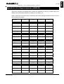
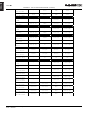
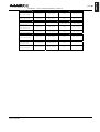
APPENDIX A : LIST OF SUPPORTED PRESETS (LOAD2.22)..................................................................................37
USER MANUAL LOAD2_22
DATE: 03/12/2004
ENGLISH
PAGE 5
ENGLISH
PAGE 6
NX242 VERSUS NX241: WHAT’S NEW ?
NX242 versus NX241: What’s new ?
The NX242 Digital TDcontroller has been designed in order to provide total compatibility with its
predecessor – the NX241 Digital TDcontroller.
What’s remain the same?
The DSP resources for both models remain the same, so new supported set-ups (i.e. firmware loads) will
be compatible with the both the NX241 and NX242 TDcontrollers. For advanced set-ups and signal
processing NEXO has released the NXtension Expander Board, which has double the available DSP
resources.
MENUs and functions remain the same; no learning curve is needed to go from the NX241 to the NX242.
The same LOAD and NXWIN software is used to update both TDcontrollers. The transition is transparent
for the user. Note however, that the NX242 can’t be flashed with LOADs prior to 2.21.
The appearance of the NX242 is identical to the NX241 except the model number. Therefore, you can
mix both units in the same rack without aesthetic problems. Please note however that both NX241 and
NX242 should have the same firmware revision (LOAD) to be phase compatible.
What’s changed?
The overall performance of the NX242 has improved significantly: 10dB more on the dynamic range, less
distortion…
The layout and ground scheme of the unit have been totally revised to cope with the most demanding
situations founded in the field (low and very high frequencies). The EMC protection on every input/output
and the new ground structure makes the NX242 immune to interference far beyond the recommended
values founded in EMC standards. As a result, there is no need for the earth lift function found on the
NX241.
The input stage is truly floating and accepts important common mode offset (resulting from very long
wiring or difference of ground potential between two connected equipments) without affecting it’s
headroom (28dBu) and performance.
The NX242 Digital TDcontroller uses a switch mode power supply (SMPS). This SMPS accepts
universal AC power input voltages in the range 90V to 264V, and requires no manual adjustment for
voltages in this range.
The NX242 is designed to accept the optional NXtension board with the ES-4 EtherSound interface and
the CAI interface, whereas the NX241 can only accept the CAI interface.
An external LCD contrast adjustment is now provided on the NX242.
NX242 USER MANUAL LOAD2_22
DATE : 12/3/2004
QUICK START
Quick Start
This section contains a summary of the most frequently asked questions by people who haven't read the
manual. You may be able to use the NX242 TDcontroller quite quickly as it has been designed to be
user friendly. However please devote some attention to reading this manual. A better
understanding of specific features of the NX242 TDcontroller will help you to operate your
system to its full potential.
WARNING: Information on the amplifiers used is MANDATORY. Before using your system you
MUST configure "MENU 2.6 AMP GAIN" and "MENU 2.7 AMP POWER". Failure to do so or to
properly connect the Sense Lines will invalidate the NEXO warranty on the attached NEXO
loudspeakers. See in “ Amplifiers (Gain, Power)” page 25 the correct way to do so.
RESET
You can reset the unit without powering off by simultaneously depressing buttons A, B & “ENTER” ()
at the same time.
Selecting cabinet family
Simultaneously depressing A & B buttons at power up or during device RESET accesses the system
change menu. Keep the A & B Buttons held until all LEDs are off. This will allow the selection of any
cabinet in any family. Using the rotary encoder, scroll through the configurations and press “ENTER”
() to load the required settings.
Select your cabinet set-up
In MENU 3.0 you will be able to choose among the different set-ups within the same cabinet family. (i.e.
you don't have to modify the amplifier to cabinet wiring).
Navigating menus
On the controller display screen, the number before the Function corresponds to the menu number. To
change the first number (this is the Main menu label) button A must be pressed. To change the second
number (this is the Submenu label) button B must be pressed. To select options, turn the encoder wheel,
or press the “ENTER” button (). Changes are immediate (no further confirmation unless clearly
stated).
Back to default
In Menu 2.5 you have the possibility to put back all MENUS to the factory default (except the amplifier
information that you have entered MENU 2.6 & 2.7).
Auto save
In case of power failure, the current set-up is saved two minutes after the last change made. At power up
the last saved settings are restored.
USER MANUAL LOAD2_22
DATE: 03/12/2004
ENGLISH
PAGE 7
ENGLISH
PAGE 8
SETTING-UP ADVICE
Setting-Up Advice
Mains Power
WARNING ! THIS APPLIANCE MUST BE EARTHED.
The green and yellow wire of the mains cord must always be connected to an installation safety earth or
ground. The earth is essential for personal safety as well as the correct installation of the system, and is
internally connected to all exposed metal surfaces. Any rack framework into which this unit may be
mounted is assumed to be connected to the same grounding circuit. (see also p.8)
NEXO TDcontrollers don’t provide a mean to switch off the unit from the front panel. As they are intended
to be rack mounted the back panel is not accessible during use. Therefore it is left to the user to provide a
disconnection mean readily operable.
Voltage setting
NEXO TDcontrollers use a switch mode power supply (SMPS). This SMPS accepts universal AC power
input voltages in the range 90V to 264V, and requires no manual adjustment for voltages in this range.
Mounting the TDcontroller in a rack (Grounding, shielding & safety issues)
The TDcontroller is intended for rack mounting. The only accessible part during use shall be the front
panel of the TDcontroller. Any space above or under the TDcontroller shall be obstructed with a blank
panel.
The rack is a free grounding and shielding structure and it provides extra shielding. Therefore, it is
desirable that the screws used to fix the TDcontroller in the frame or rack provide an electrical contact
between the chassis of the TDcontroller and the rack.
The primary reason for grounding is safety. Conformance to the applicable requirements of the
authorities having jurisdiction is, of course, mandatory. However, grounding also has an impact on
electromagnetic compatibility. From the EMC point of view, it is desirable to have a low impedance
ground network, as a current flowing in the ground network will then produce low voltage in the network.
A low impedance network can be obtained using a multipoint ground scheme, with as many closed
ground loops as is economically possible.
Fuse
The fuse provided in the unit will not blow during normal operation. If the fuse blows the TDcontroller
has malfunctioned. This fuse must only be changed by NEXO certified service personnel. In any case
do not replace the fuse with a non-certified NEXO fuse, as this will invalidate the NEXO warranty.
CAUTION!
This servicing instruction is for use by qualified service personnel only. To reduce the risk of electric
shock, do not perform any servicing other than that contained in the operating instructions unless you are
qualified to do so.
NX242 USER MANUAL LOAD2_22
DATE : 12/3/2004
SETTING-UP ADVICE
Recommendations for wiring the sense lines
The impedance of the sense inputs of the TDcontroller are high, so currents are low and therefore light
duty cable can be used. If the TDcontroller is housed in the amplifier racks an unshielded cable may be
used.
If the TDcontroller is located remotely - at the mixing position - a shielded cable is recommended, without
using the shield as a conductor. The cable must be well protected from public access, as it carries
potentially dangerous amplifier voltage.
When one of the channels is not being used and the corresponding sense line is disconnected, cross talk
onto the inactive sense line may in some cases produce signals capable of causing the inadvertent
illumination of the Sense LED on that channel; although this has no effect on the internal operation of the
TDcontroller, it can be cured by short-circuiting the terminals of the inactive sense line.
Recommendations for wiring the audio outputs
The output stages can drive several amplifiers in parallel; however it is not advisable to work with loads of
less than 1kOhm(and strictly forbidden to drive less than 600Ohms). It is best to check the impedance
characteristics of the amplifier inputs - supplied by the manufacturer - to check how many amplifier
channels can be paralleled. Where precise information is not available (and taking 10kOhm as the
minimum value possible), ten channels in parallel per output is a sensible maximum.
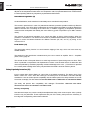
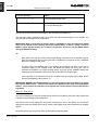
Electromagnetic environments
The emission (this word describes all types of electromagnetic noise radiated by the equipment)
requirements which have been applied to Nexo’s TDcontrollers are the stringent requirements of the
”Commercial and light industrial environment” of the product family EMC standard for emission.
The immunity (this word describes the ability to cope with electromagnetic disturbance generated by
other items and natural phenomena) requirements that we have considered exceed those applicable to
the ”Commercial and light industrial environment” of the product family EMC standard for immunity. In
order to provide a further safety margin, we recommend that you do not operate the TDcontrollers in the
presence of electromagnetic interference exceeding half of the limits found in this standard.
These two EMC standards are those applicable to pro-audio equipment for the implementation of the
”EMC directive”.
Mixing Desk
Amplifier
Low Z
Analogue signal cables
Low Z
The TDcontroller is intended to be used with
USER MANUAL LOAD2_22
DATE: 03/12/2004
3
+
2
1
PE
1
3
3
+
2
PE
SHIELD
1
SHIELD
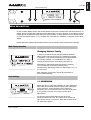
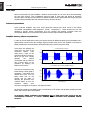
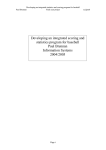
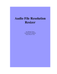
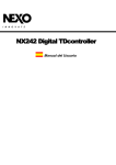
Analogue signals should be connected to the input
and output ports of the TDcontroller via shielded
twisted pair or starquad cable fitted with XLR
connectors on the TDcontroller side. We
recommend the use of low transfer impedance
cables with a braided shield and a transfer
impedance below 10 mΩ/m. For the sense inputs,
the noise requirements are not as stringent, and
any kind of twisted pair cable will be adequate.
1
2
-
+
3
-
PE
2
+
Low Z
Low Z
IN
TDcontroller
OUT
Safety
Ground
ENGLISH
PAGE 9
SETTING-UP ADVICE
symmetrical (balanced) sources (for instance a mixer) and symmetrical loads (for instance a power
amplifier (see figure). You can see that the TDcontroller provides a low impedance path between pin 1 of
its XLR connectors and its chassis. The TDcontroller can sustain high current in pin 1 without
degradation of output noise. We recommend that the sources and loads you use have the same
desirable characteristics.
It is sometimes claimed that connecting cable shield at both ends creates ground loops, and that the
current flowing in such loops will produce noise. This is not the case for most professional audio
equipment. In short, there are two kinds of loops in which voltages are present: the loops formed by
signal wires, and the loops formed by grounded conductors, among which are protective earth
conductors (PE) and signal cable shields.
When a cable shield is grounded at both ends, a loop is closed, and the resulting current causes a
reduction of the voltage induced on signal lines. This effect is what the cable shield is intended to
produce, since this is how it protects your signal from magnetic fields.
Amplifier
Low Z ?
Mixing Desk
0V
Low Z ?
1
3
-
+
2
1
?
1
3
3
+
2
PE
SHIELD
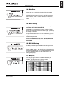
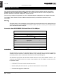
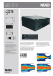
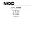
If you are using an asymmetrical
(unbalanced) source (not recommended),
it is best to use a shielded twisted pair and
to connect wire 3 of the cable to the shield
at the source output end (see figure). This
technique prevents noise currents flowing
on the return path of the signal. If you are
using an amplifier with an asymmetrical
(unbalanced) input, it is best to use a
shielded twisted pair, and to connect wire 3
at the TDcontroller end only, as shown in
Fig. 2. This keeps a good capacitance
balance for the signal, however noise
currents flow on the return path of the
signal. (Note that this is only acceptable for
a short cable).
SHIELD
ENGLISH
PAGE 10
1
2
-
+
3
-
PE
2
Safety
Ground
+
Low Z
Low Z
IN
TDcontroller
OUT
If you are using a symmetrical (balanced) source or amplifier which is prone to become noisy when a
current of less than 100 mA at the mains frequency (50 Hz or 60 Hz) is sourced into pin 1 of its XLR
connectors, you might consider opening the ground loops.
NX242 USER MANUAL LOAD2_22
DATE : 12/3/2004
SETTING-UP ADVICE
HEADROOM adjustement allows the signal to be scaled to the Analogue to Digital
Converter, keeping the unity gain of the NX242
High end AD converter :24bit allowing a 110dB Dynamic range (analogue to analogue)
A (LEFT)
B (RIGHT)
Maximum Clipping input : 28dBu
Nominal Input impedance : 19.8kOhm
Common Mode Ratio (CMRR): 85dB
Very High Immunity to common mode interferences
FLOATING
T
BALANCED IN
INPUTS
High end Floating balanced Input
Blanking panel
In this slot goes the optional NXtension-CAI and NXtension-ES4 Expander Boards.
Mute & Solo Buttons
CAUTION - RISK OF FIRE
DO NOT OPEN
Red LED : Muted Channel
Channel monitoring
Channel1
Red LED Peak Limiting : Prevent your amplifier from overloading
Yellow LED Protections : Prevent speaker Displacement and Temperature failures
Green LED Signal : Monitor amplifier signal & displays sense error alerts.
High end DA 24bit convertion
Delivers up to 28dBu into 600Ohm load
Channel 3
Heavy Duty Balanced Output Stage.
BALANCED
ALA
OUTPUTS
Input Overload / DSP Clip
Channel 2
LCD contrast adjustment
Channel 4
Rotary Encoder
Enter Button
03105
Switch mode power supply
Detachable Power cord shall comply with your country regulation.
Allows continuous operation between 90V and 260V. No Adjustment required.
ON/OFF Mains Switch
USER MANUAL LOAD2_22
DATE: 03/12/2004
+ 2 -
+ 1 50 - 60Hz 45W
CAUTION !
To reduce the risk of electric schock, grounding
of the center pin of this plug must be maintained.
Sub Menu B Selection
Main Menu A Selection
115 - 230V
Menu Selection
NX242
N
LCD screen
+ 3 + 4 -
(from amp terminals)
SENSE INPUT
RS23
32
Sense Line Connector to amplifier
Allows the best use of the protection process, including the amplifier analysis (gain and
clipping voltage). Failing to connect the sense connector may damage your speakers.
MADE IN FRANCE
GeoT 4805-2815
48
Crossover
ss
75Hz
sept.04
NX242 TDcontroller
Serial Connection RS232 to PC
Connect your NX242 to the COM port of your PC to update the NX242 Firmware.
ENGLISH
PAGE 11
ENGLISH
PAGE 12
GENERAL DESCRIPTION
GENERAL DESCRIPTION
Global architecture
Global architecture is based upon a full 24bit audio path with 48bit core calculator running at 100 Million
Instructions per Second. Featuring:
2 analogue inputs (floating balanced) 24bit resolution ADC.
4 analogue outputs (balanced) 24bit resolution DAC.
4 sense inputs (balanced) 16bit resolution ADC.
Set-up configurations
The audio path is automatically adjusted within the NX242 according to the setups (PS15, GEOT, CD18)
chosen by the user. This will affect the delays and gain control. For instance changing the gain of a CD18
cabinet will affect two channels at a time, changing the gain on a 3 WAY cabinet (e.g. Alpha) will affect
three channels, etc.
At the time of writing, the following configurations are used (for a complete description Appendix A on
page 37 for the list of setups currently supported)
Channel 1
Channel 2
Channel 3
Channel 4
unused
unused
2 WAY Passive Cabinet
2 WAY Passive Cabinet
Channel 2 duplicated
Sub
2 WAY Passive Cabinet
2 WAY Passive Cabinet
Sub
Sub
2 WAY Passive Cabinet
2 WAY Passive Cabinet
1WAY Active cabinet
1WAY Active cabinet
1WAY Active cabinet
1WAY Active cabinet
unused
1WAY Active cabinet
1WAY Active cabinet
1WAY Active cabinet
Cardioid back
Cardioid front
Active cabinet
unused
Cardioid back
Cardioid front
Active cabinet
Channel 2 duplicated
Cardioid Sub 1 back
Cardioid Sub 1 front
Cardioid Sub 2 back
Cardioid Sub 2 front
You may have noticed that certain configuration (4 passive cabinets for instance) are not supported.
Using those configurations requires the addition of the optional NXtension Expander Board. Please refer
to the separate manual for additional information.
NX242 USER MANUAL LOAD2_22
DATE : 12/3/2004
BLOCK DIAGRAM DESCRIPTION
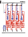
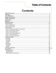
Block diagram description
Equalisation & Filtering
The number between parenthesis refers to the number circled in the block diagram.
Subsonic and VHF filtering (1)
Low and high-pass filters are used to filter out frequency components that could possibly degrade the
performance of the TDcontroller and amplifiers. The filters are optimised to work in conjunction with
overall system response.
The high pass filters are also extremely important as they optimise excursion at very low frequency which
is a very important safety factor. (Therefore do not use set-ups which are not designed for the cabinet
you are using).
Equalising wideband acoustical response (2)
This wideband equaliser section achieves the correction required to obtain a flat system response, as the
cabinets are acoustically designed for maximum efficiency on the whole frequency range. Active rather
than passive attenuation allows the lowering of amplifier voltages for a given output SPL and therefore
increases
the
maximum
SPL
achievable
with
the
same
amplifier.
Active equalisation also extends system bandpass especially at low frequencies where acoustical
performance is limited by cabinet size.
Equalising single component response (3)
This equaliser set allows acting on a specific driver after the crossover, rather than the on wideband
section. This allows to EQ one driver without affecting the others (cleaning out of band response, fine
tuning in a crossover…). All the parameters are factory set.
Crossover section (4)
Crossover between different bands is tuned for every set-up of every cabinet. Each crossover is
customized so that each transducer will fit with its neighbour by achieving a perfect phase alignment.
Unconventional, crossover-defined filters are applied, ranging from 6dB/octave to near infinite slopes
according to the type of crossover desired. Time alignment is also unconventionally achieved, by
combining crossover filter group delays with allpass and/or frequency dependent delays.
User set-up, Array EQ (5)
A basic Array EQ is currently implemented in the NX242. The cut off frequency of a low-shelving filter is
factory tuned for each cabinet set-up. The user has access to the gain of this filter. The array EQ is tuned
in order to reproduce the effect of the bass coupling, allowing the user to increase or diminish the effect of
the stacking.
USER MANUAL LOAD2_22
DATE: 03/12/2004
ENGLISH
PAGE 13
NX242 USER MANUAL LOAD2_22
DATE : 12/3/2004
8
SENSE 4
A/D
A/D
A/D
6
SENSE 2
7
SENSE 3
A/D
HEADROOM
5
SENSE 1
INPUT L
INPUT R
0
0
AMP POWER
Signal
EQ
AMP POWER
Signal
AMP POWER
Signal
AMP POWER
Signal
AMP VOLTAGE AMP GAIN
FALLBACK
AMP VOLTAGE AMP GAIN
FALLBACK
AMP VOLTAGE AMP GAIN
FALLBACK
AMP VOLTAGE AMP GAIN
FALLBACK
INPUT VU-METER
A/D
EQ
2
INPUT VU-METER
A/D
Command
Command
ChassisTemp.
Voice Coil Temp.
9
Command
ChassisTemp.
Voice Coil Temp.
ChassisTemp.
Voice Coil Temp.
Command
PEAK SIMULATION 4
Command
HF TEMPERATURE 4
Command
LF TEMPERATURE 4
Disp.
displacement
Command
DISPLACEMENT 4
PEAK SIMULATION 3
Command
HF TEMPERATURE 3
Command
LF TEMPERATURE 3
Disp.
Command
displacement
Command
DISPLACEMENT 3
PEAK SIMULATION 2
Command
HF TEMPERATURE 2
Command
LF TEMPERATURE 2
ChassisTemp.
Voice Coil Temp.
Command
displacement
Command
DISPLACEMENT 2
PEAK SIMULATION
12
HF TEMPERATURE
Command
1
R
PHYSIO 2
Voice Coil Temp.
Command
ChassisTemp
PHYSIO 1
PHYSIO 4
Voice Coil Temp.
Command
ChassisTemp
PHYSIO 3
10
Voice Coil Temp.
Command
ChassisTemp
Voice Coil Temp.
Command
ChassisTemp
2
L
3
R+L
displacement
LF TEMPERATURE
9
Disp.
8
DISPLACEMENT 1
Disp.
SHELVING
5
SHELVING
ATT/REL.3
ATT/REL.2
ATT/REL.1
ATT/REL.
1
R1
2
L
2
L
3
R+L
1
R
2
L1
3
R+L 1
3
R+L
1
R
11
2
L
3
R+L
1
R
PATCH 4
PATCH 3
PATCH 2
DELAY 3
DELAY 2
13
DELAY 4
PATCH
DELAY 1
4
1
EQ
EQ
EQ
3
EQ
VCA
VCA
VCA
VCA
6
7
7
EQ
EQ
EQ
3
EQ
4
Analogue path
Digital Audio
Digital servo & protections
MUTE
MUTE
MUTE
MUTE
DAC
DAC
DAC
DAC
OUTPUT CHANNEL 1
OUTPUT
CHANNEL 2
OUTPUT
CHANNEL 3
OUTPUT
CHANNEL 4
NX242 Digital TDcontroller BLOCK DIAGRAM
HEADROOM
ENGLISH
PAGE 14
BLOCK DIAGRAM DESCRIPTION
BLOCK DIAGRAM DESCRIPTION
Protection
VCAs (6) and VCEQs (7)
Each channel has its own simulation and protection process.
Each audio channel contains a combination of controlled gain stages (let's call them VCA’s as in our
analogue circuitry). These VCA's are embedded into complex composite structures in order to change
their basic operation into frequency selective attenuation. This operation is similar to that of a voltage
controlled dynamic equaliser (VCEQ).
Each VCEQ and VCA is controlled by the synthesis of several signals issued from the various detection
sections. That synthesis is in fact the envelope of those signals, with an optimised release and attack
time for each VCEQ and VCA (depending on its frequency range and the cabinet selected).
Displacement control (8)
The sense input signal is sent to a shaping filter producing a signal whose instantaneous amplitude is
proportional to the voice coil excursion. This signal, after rectification, is compared to a preset threshold
matching the maximum usable value, as determined from laboratory measurements.
Any part of the signal exceeding the threshold is sent to the VCEQ control buffer while the VCEQ acts as
an instantaneous limiter (very short attack time) to prevent displacement from overriding the maximum
permissible value.
Temperature control (9)
Each sense signal is fed into a shaping filter (one per transducer), each one producing a signal
proportional to the instantaneous current flowing into the voice coil of the transducer. After rectification,
this signal is integrated with attack and release time constants equivalent to the thermal time constants of
the voice coil and chassis, producing a voltage, which is representative of the instantaneous temperature
of the voice coil.
When this voltage reaches the threshold value corresponding to the maximum safe operation
temperature, the VCA becomes active to reduce the Audio signal level and limit the effective temperature
to fall under the maximum usable value.
In order to avoid detrimental effects induced by very long release time constants coming from the
temperature detection signal (level being reduced for an extended period, « pumping » effects...), the
detection signal is modulated by another voltage integrated with faster time constants matching the
sound level subjective perception. This allows the controller to reduce the effective operation duration of
the temperature limiter and make it sound more natural, while the efficiency of protection is fully
preserved and operation thresholds are unaffected (kept as high as possible).
Physiologic Dynamic Control (10)
The so-called Physiologic Dynamic Control is intended to avoid unwanted effects as a result of a too long
attack time constant. By anticipating the operation of the temperature limiter, it prevents a high level
Audio signal appearing suddenly then being kept up for a period, which is long enough to trigger the
temperature limiter. Without this, a rough and delayed gain variation would result which would be quite
noticeable and unnatural.
USER MANUAL LOAD2_22
DATE: 03/12/2004
ENGLISH
PAGE 15
ENGLISH
PAGE 16
BLOCK DIAGRAM DESCRIPTION
The Physio control voltage acts independently on the VCA with its operation threshold slightly lower (3
dB) that of the temperature limiter and a low compression ratio; its optimised attack time constant allows
it to start operating without any subjectively unpleasant transient effects.
Interchannel regulation (11)
As described before, each transducer is individually servo-controlled for temperature.
This means in practice that, in case of a potential risk detected, protective operation would only affect the
concerned driver. Your driver will be protected but the overall system tonal balance could be altered if the
different channels are not heating at the same time. In addition, triggering a temperature protection
means that the loudspeaker has already lost some efficiency (power compression up to 3dB in extreme
cases)
The purpose of interchannel regulation is to cancel that effect by linking VCAs together. When the
protection is activated on one channel and reaches a predetermined threshold, the regulation section
begins to correct the balance between the different channels (HF, MF, and LF) by acting on the
concerned VCA.
Peak limiter (12)
The peak limiter primary function is to avoid massive clipping of the amp, which can have some very
audible artefacts.
The threshold of the peak limiter is determined by the user to match its amplifier. See in “ Amplifiers
(Gain, Power)” page 25.
The second function of the peak limiter is to avoid huge amounts of power being sent to a driver. Each
driver is protected in temperature and displacement but there could be other factors of destruction that
cannot be predicted by simulation (especially mechanical damage to the cone…). Each driver is specified
for a certain power handling and a factory set peak limiter threshold is tuned to avoid any abuse.
Delay & polarity inversion (13)
Input to output delay without filtering is 2.2ms (due to the digital processing). The latency time of the
NX241 used to be 1.4ms. Since the LOAD2_21 the latency time of the NX241 has been artificially
extended to 2.2ms to achieve phase compatibility with the NX242 (and so the delay between the 2 units
is less than a sample). For that reason: Do not mix NX241 with a LOAD earlier to 2.20 with the NX242
This delay will prevent also compatibility with analogue TDcontrollers. ANALOGUE
TDCONTROLLER SHOULD NOT BE MIXED IN THE SAME SYSTEM.
AND DIGITAL
Factory set-up delay
Note that each output may contain a small phase adjustment delay at the crossover point. Also, a polarity
inversion may be performed. These adjustments are part of the factory set-ups and are necessary to
time-align the corresponding cabinet that is selected.
NX242 USER MANUAL LOAD2_22
DATE : 12/3/2004
BLOCK DIAGRAM DESCRIPTION
User set-up delay
Following user delay adjustment is possible:
GLOBAL: Affecting all channels at the same time (delaying all the system for application as delay
towers…)
MAIN: Affecting only the channels driving the MAIN system (differ in case of TWO cabinet or 3WAY
cabinet)
SUB: Affecting only the channels driving the SUB system.
GLOBAL and MAIN/SUB delays are cumulative up to 150m per channel (about 450ms, 500 feet).
Audio Input/Output
See also the wiring recommendations in the “setting up advices” section, at the beginning of this manual.
Floating balanced audio input
A new ruggedized, truly floating, high-end performance Input stage has been developed for the NX242.
In the max HEADROOM position, it is accepting input level up to 28dBu and keeping this performance
when driven by unbalanced impedance sources or when submitted to high common mode level.
The analogue inputs are on 3 pin female XLR connectors with positive and negative signal polarities on
pins 2 and 3 respectively. Pin 1 is directly coupled to the chassis.
The input signal can be adjusted in MENU 1.1 HEADROOM in order to avoid clipping of the A/D
converter. See corresponding paragraph (MENU section page 19)
Balanced audio output
The analogue outputs are on 3-pin male XLR connectors with positive and negative signal polarities on
pins 2 and 3 respectively. Pin 1 is directly coupled to the chassis. The output will deliver a full-scale output
of +28dBu(balanced 600 / 1nF load.)
During A/C power up of the NX242, all outputs are muted by firmware-controlled relays (strapping pin 2
and pin 3 of each output).
USER MANUAL LOAD2_22
DATE: 03/12/2004
ENGLISH
PAGE 17
ENGLISH
PAGE 18
BLOCK DIAGRAM DESCRIPTION
General functions
Remote sense lines
Line input (–18dB less than the amplifier gain) is allowing remote sensing. You will need to use this
function to have an 18dB gain attenuator near the amplifier. This function enables you to keep the
TDcontroller at the mixing position and still being able to feed an attenuated amplifier voltage (for safety
reasons) to the sense line connector.
Reset
Holding down the three menu buttons (A, B, ) simultaneously will reset the unit. Reset has the same
effect as powering on and off the unit. The unit will mute (hardware) for 5 seconds with all LED’s on. The
unit will then return to the last set-up automatically saved (every 2 minutes).
Resetting the unit from the front panel is needed to change the cabinet family (Press the three buttons to
reset then let go of the ENTER button to enter into MENU 0). In that case you will have to keep the A & B
Buttons until all LEDs light off.
Mute/Solo buttons
Front panel, direct access. The Mute (or Solo) mode is selected in the user menu. Please note that these
MUTEs are soft mute and are therefore not operating output relays.
Display & Indicators
User control of all settings is via two menu scroll pushbuttons, an additional assignable pushbutton, an
assignable rotary encoder and a backlit 16*2 character display.
Three LED’s per channel for sense (green), peak limit (red) protects (yellow). Four dedicated LED’s are
situated alongside the associated MUTE/SOLO button.
Two LED’s to indicate input overload and signal clipping into the DSP.
Default screen will pop up after 2 minutes and display the current set-up.
Contrast adjustment
A hole in the front panel allows the adjustment of the contrast of the LCD screen.
Serial link / Downloader
The unit can be RS232 linked to any PC in order to download new versions of Firmware using a
Windows compatible Downloader program. See corresponding chapter page 32.
NX242 USER MANUAL LOAD2_22
DATE : 12/3/2004
MENU DESCRIPTION
-- LOAD2_20 -(c) NEXO 2004
MENU DESCRIPTION
On the controller display screen, the number before the Function corresponds to the Menu Number. To
change the first number (this is the Main menu label) button A must be pressed. To change the second
number (this is the Submenu label) button B must be pressed. To select options, turn the encoder wheel,
or press the ENTER button (). Changes are immediate (no validation is required unless clearly
stated).
Please refer to the release notes issued with each new download to track eventual menu changes.
Main Family Selection
Changing Cabinet Family
In order to prevent end-user changing between different
NEXO system set-ups during use, the following procedure
is obligatory. This procedure has been purposely designed
to avoid any mistake. It is nevertheless very easy to
change set-up among the same family (see menu 3)
Depressing A & B buttons while the NX242 is resetting.
You can reset the unit without powering off by
simultaneously depressing buttons A, B & ENTER () at
the same time.
Note: Selecting a new family will set all parameters to
factory default settings.
User settings
1.1 HEADROOM
Allows the user to adjust the headroom (8 steps, 3dB each)
before the A/D converter without changing the overall gain
of the processor. Factory default is set to maximum
headroom (and so, maximum noise). This can be adjusted
if you feel the processor is too noisy for lower level
applications.
An Input bar graph meter displays input level and
headroom before input clip. The maximum of the left and
right input is shown on the meter. Note that the meter does
not show DSP clipping.
USER MANUAL LOAD2_22
DATE: 03/12/2004
ENGLISH
PAGE 19
ENGLISH
PAGE 20
MENU DESCRIPTION
The input meter is accessed through the MENU 1.1
(HEADROOM) by depressing ENTER WX button. Press
the ENTER WX button to toggle between the meter and
the normal HEADROOM screen. Note: In meter mode, the
default screen is not activated.
The meter also pops up automatically when the signal is
above a certain threshold.
The red arrow above illustrates the Headroom available
before clipping of the input converters of the NX242. The
dynamic range of the meter is 24 dB. The scale is given
below; maximum being 0dBFS (the red LED marked ‘in
clip’ will light).
-24
-12
-6
-3
A permanent peak hold allows you to see if input clipping
has reached. Changing the headroom (by turning the
wheel) resets the peak hold indication. You can also reset
the peak hold (without changing the headroom) by pressing
the enter WX button twice.
To set the HEADROOM correctly, feed a typical example of
the loudest desired program level into the NX242. Reduce
the Headroom by turning the wheel anti-clockwise until the
INPUT LED or DSP LED indicates the NX242 has reached
clipping. Then go one click backwards (turn the wheel
clockwise). The signal should now be clearly visible on the
meter scale, but without reaching the right-hand end of the
display.
1.2 DELAYS [Sub / Main / Global]
Each output channel can be delayed by up to a maximum
(global + individual delay) of 450ms (150m). See page 17
The unit can display in [FEET / METRES / SECONDS] as
required. Delay is adjustable in 10cm (0.3ms) increments.
The control pot will accelerate through the adjustments
faster according to the speed of use.
1.3 OUT Levels
[Global / HF /MF / LF / SUB]]
Adjust overall & separate TDcontroller gain with this menu.
These gain controls are provided to adjust the tonal
balance of the system by acting on separate channels. You
can also compensate for gain differences between different
amplifiers. (Although the use of differing gain structure
amplifiers in the same set-up is possible it is not
recommended).
Each of the individual or global gain is +/- 6dB. (Step
NX242 USER MANUAL LOAD2_22
DATE : 12/3/2004
MENU DESCRIPTION
0.5dB)
1.4 Mute/Solo
Allows the user to switch the function of the front panel
channel buttons between Mute and solo mode.
Individual channel muting is made in the DSP processor
itself. However, when all 4 MUTE buttons are active the
output relays bypass the circuitry, to eliminate any residual
noise.
1.5 SAVE Set-up
It is possible to store and recall up to 10 user set-ups but
excluding MUTE BUTTONS STATE.
Additionally the current set-up is saved in case of power
failure every two minutes after the last change. At power up
this set-up is restored.
Set-ups are numbered from 1 to 10. When saving your setup you can choose a reference name up to 6 characters for
identification purposes.
NOTE: ALL SAVED SETUPS WILL BE ERASED WHEN
DOWNLOADING A NEW VERSION OF THE
SOFTWARE.
1.6 RECALL Set-up
Recalling a user set-up is forbidden if the family of cabinet
is not the same.
When recalling a set-up, the unit will stay in the recall menu
allowing another selection for comparison. Switching from a
set-up to another is glitch-free and instantaneous (no
muting takes place).
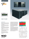
1.7 Array EQ
One array EQ gain control of +/- 6dB (0.5dB step) is
included. This filter frequency is factory tuned.
AlphaTD Controller Array EQ / Frequency (Hz) / Gain (dB)
10.000
8.0000
6.0000
4.0000
2.0000
0.0
-2.000
-4.000
-6.000
-8.000
-10.00
20
USER MANUAL LOAD2_22
DATE: 03/12/2004
100
1k
10k
20k
ENGLISH
PAGE 21
ENGLISH
PAGE 22
MENU DESCRIPTION
System settings
2.1 Revision [soft & hard rev]
Displays the revision number of the LOAD; DSP
SOFTWARE; FLASH BOOT; HARDWARE and SERIAL
NUMBER. Turn the encoder to access to the different
revision screens.
Check on our web site www.nexo.fr if your unit is updated.
2.2 Security [password]
The user password facility allows switching between "free
access", "unit locked" and "Change password. The factory
default password is NEXO.
This allows you also to get into an INSTALLER menu.
Please contact your NEXO dealer if access required.
2.3 Reserved
This menu was formally used in the NX241 to control the
EARTH LIFT. This function is not available anymore in the
NX242 (due to a change in our “ground plane” politic). To
keep the coherence of the MENUs between NX241 &
NX242 we have nevertheless keep this slot unused.
2.4 SENSE GAIN
Allows switching between line level sense lines and
amplifier level sense lines. (0 or 18dB gain on the sense
line)
2.5 Restore Default
Restores the factory defaults. System related values like
the AMP GAIN and AMP Power will not change.
NX242 USER MANUAL LOAD2_22
DATE : 12/3/2004
MENU DESCRIPTION
2.6 AMP GAIN
Adjustable from 20dB to 40dB nominal Amp Gain in 0.5dB
steps for each channel.
See in “ Amplifiers (Gain, Power)” page 25 a complete
description of this menu, and the way to adjust this setting.
2.7 AMP POWER
Allows you to enter a Nominal Amp RMS power into
8ohms. Adjustable from 200 Watts to 5000 Watts in 50W
steps for each channel.
See in “ Amplifiers (Gain, Power)” page 25 a complete
description of this menu, and the way to adjust this setting.
2.8 Reset measure & Sense Alert
The first section of Menu 2.8 allows you to reset the gain
and power reading to default settings. If the ENTER
WXbutton is pressed, the values are reset, and menu 2.6
is displayed again. Use this feature if any physical changes
have occurred in your system to start again the
measurement process.
Turn the encoder wheel to reach the second section of
Menu 2.8, which is the alert disable menu. Press the enter
WX button to set the alerts (Led flashing) on or off. Once
disabled, the LEDs will not flash if gain settings are
incorrect. This parameter is saved every time the NX242
returns to the default screen, or when a setup is saved in
the menu 1.5.
Configuration select.
3.1 System Config.
Changing a set of parameters within the same family is
made immediately and is barely audible.
USER MANUAL LOAD2_22
DATE: 03/12/2004
ENGLISH
PAGE 23
ENGLISH
PAGE 24
MENU DESCRIPTION
Input Patch, MENU3.2
Each output (or group of outputs when a system uses more
than one output per cabinet – like the Alpha M3 or
CD12/CD18 subs) may be configured to receive either
LEFT, RIGHT or (LEFT+RIGHT) inputs. The Left and Right
mode sums the two inputs together, but attenuates the
level by 6dB to compensate.
It is thus possible to drive the main system from the LEFT
input while the sub is driven by the RIGHT input and fed to
the AUX of the mixing desk. However some precautions
must be taken while splitting the system between MAIN
and AUX outputs of the mixing desk. See the application
note at the end of this manual.
NX242 USER MANUAL LOAD2_22
DATE : 12/3/2004
AMPLIFIERS (GAIN, POWER)
Amplifiers (Gain, Power)
Power
NEXO recommends high power amplifiers in all cases. Budget constraints are the only reason to select
lower power amplifiers. If an incident occurs on an installation without protection the fact that amps only
generating half their rated output power (-3dB) are used will not change anything in respect of possible
damage. This is due to the fact that the RMS power handling of the weakest component in the system is
always 6 to 10 dB lower than the amps' ratings.
Current rating
It is very important that the amplifier behaves correctly under low load conditions. A speaker system is
reactive by nature, on transient signals like music it will require much higher instantaneous current than
its nominal impedance would indicate (four to ten times more). Amplifiers are always specified by
continuous RMS power into resistive loads (which is irrelevant); the only useful information in that respect
is the specification into a 2 ohms load. It is possible to make an amplifier listening test by loading them
with twice the number of cabinets considered for the application (2 speakers per channel instead of one,
4 instead of 2…) and modulating at high level (onset of clipping). If the signal does not noticeably
deteriorate the amplifier is well adapted (overheating after approximately ten minutes is normal but
thermal protection must not operate too quickly after starting this test).
Amplifier gains
As you already read in the Quick Start section Information on the amplifiers used is MANDATORY. This
value is the key of a correct protection setting. It is very important to know the gain and power of all
amplifiers present in your set-up. The NX242 Digital TDcontroller provides tools to help you in this task
(although the process in not totally automated for safety reason).
Some amplifier brands have an identical input sensitivity for models of different power rating (this means
DIFFERENT GAIN for each model). This problematic practice, inherited from non-professional
applications, is easily detected when the manufacturer specifies the same input sensitivity for all its range
(like 775mV/0dBm or 1.55V/+6dBm). This translates to very high gain values on higher power models.
Other brands do offer constant gain but only within a given product range (like higher gain on all semiprofessional amps). Even if a manufacturer is conscious of this problem and applies the constant gain
rule to all its models, the value he chooses is not necessarily the same as other manufacturers.
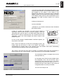
How to set correct GAIN and POWER information in the NX242
Menu 2.6 Amp Gain
The first line of the display shows the value entered by the user
(hereafter referred to as “user gain”, while the second line
displays the value read by the NX242 directly from the sense
lines (hereafter referred to as “read gain”. The enter WX button
allows the user to swap between channels.
USER MANUAL LOAD2_22
DATE: 03/12/2004
ENGLISH
PAGE 25
ENGLISH
PAGE 26
AMPLIFIERS (GAIN, POWER)
The NX242 will display the following messages:
Displayed Message…
Means…
Read gain: 26.0dB
The last measured gain value.
No Reading yet..
The average of the output signal is too low (< 28dBV)
to compute the amp gain.
You will also be warned of any setup problems with LED alerts (see MENU 2.8).
This read gain value is intended to help you to check the actual measured gain of your amplifier. The
user gain and the read gain should be the same.
IMPORTANT: Bear in mind that any changes made in the MENU are only saved when the NX242
returns to its default screen showing the current cabinet family, or when a setup is saved in
MENU 1.5 (gain & power settings are common to all presets). Do not turn off your NX242 before
saving the amplifier settings.
NB:
Even when not in use, do not leave sense inputs floating; connect them to an amplifier output or
short circuit the sense input to avoid cross-talk or interference in the sense circuitry. Otherwise,
false error messages could result.
The gain value is not modified even if the amplifier has reached its clip point. In the case of
continuous clipping of the amplifier output, the NX242 will display the wrong gain value of
(because the amplifier is no longer working linearly anymore). Some amplifiers reduce their
output gain when overloaded. This may be seen on the NX242’s computed gain.
If the Input LED or the DSP LED are lit, the computed value of the gain may be false. Please
increase the Headroom value in Menu 1.1 .
IMPORTANT: NEVER insert digital equipment or any kind of signal processing (delay lines, digital
EQ, amplifier DSP modules…) between the output of the NX242 and the input of the loudspeaker
cabinet. This is because any alteration to the signals may interfere with the sensing & protection
algorithms.
Menu 2.7 Amp Power
This menu will help you to enter the amplifier power value into your NX242. This power value will be used
to determine the threshold of the peak limiters.
The first line of the menu displays the amp power entered by the user in the NX242. The second line
displays the value the NX242 has found by scanning the highest peak value reached during amplifier
clipping.
To properly set the user amp power value, please follow the following steps:
NX242 USER MANUAL LOAD2_22
DATE : 12/3/2004
AMPLIFIERS (GAIN, POWER)
1. Unplug all loudspeaker cabinets in the system.
2. Set the NX242 on the [4 S2 cabinets S2-80 Hz] setup.
3. Ensure that the amp volume controls are set to maximum (i.e. no attenuation).
4. Ensure that the menu 2.7 user value is put to 5000W (so the peak limiting will not interfere with
the measurement)
5. Feed Pink noise into the system until the amplifier is consistently clipping.
6. Read the value from the display and enter it in the user value.
The Amp power reading is a real time process and will also display a measurement while operating the
system on real conditions. However the result may slightly vary according to the setup, the frequency of
clipping, interactions with protections.
Menu 2.8 Sense Alerts & reset
In addition to the Amp Gain display in MENU 2.6 LED visual
alerts will be triggered if user gain and read gain are not the
same. Note that there are no visual alerts on the POWER
computations in MENU 2.7 “Amp power”.
Flashing Mode…
Means…
The measured gain value is under user gain
(and thus the system is over-protected)
The measured gain value is above the user gain
(and thus the system is under-protected)
Small differences are allowed, i.e. there will be no alert if the measured gain is more or less than 1 dB of
what the user has entered.
The first section of Menu 2.8 allows you to reset the gain and power reading to default settings. If the
enter WXbutton is pressed, the values are reset, and menu 2.6 is displayed again. Use this feature if any
physical changes have occurred in your system to start again the measurement process.
Turn the encoder wheel to reach the second section of Menu 2.8, which is the alert disable menu. Press
the enter WX button to set the alerts (Led flashing) on or off. Once disabled, the LEDs will not flash if gain
settings are incorrect. This parameter is saved every time the NX242 returns to the default screen, or
when a setup is saved in the menu 1.5.
USER MANUAL LOAD2_22
DATE: 03/12/2004
ENGLISH
PAGE 27
ENGLISH
PAGE 28
AMPLIFIERS (GAIN, POWER)
Gain value
NEXO recommends low gain amplifiers: +26dB is recommended, as it is at the same time adequately
low and quite common. This considerably improves signal to noise ratio and allows all preceding
electronic gear, including the TDcontroller, to operate at optimum level. Remember that using a high gain
amplifier will proportionally raise the noise floor level by the same amount.
Advanced protections
Some high-end amplifiers may have some advanced functions like those found in the NX242
TDcontroller ("loudspeaker offset integration", "limiter", "compressor"...). These functions are not well
adapted to specific system requirements and may interfere with existing protection within the
TDcontroller. NEXO do not recommend using these functions with the NX242 TDcontroller.
Amplifier Latency effects on protection
In order to provide advanced functions (not always relevant for NEXO equipment) some amplifiers use a
digital preamp section where the analogue signal provided at the input of the amplifier is converted to
Digital, treated then converted back to analogue before being send to the power stage.
Such amps are delaying the
signal from the value of the
conversion latency. (This
value reach 1.13ms on the
CROWN ITECH for instance).
When you put such a delay
between
the
NX242
TDcontroller and the cabinet it
has a strong effect on the
protection by delaying the
effect from the cause…
Peak Limiter no latency
1
0.5
0
−0.5
−1
0
5
10
15
20
Peak limiter with 1.13ms amplifier latency
1
Lets take for example a peak
0.5
limiter limiting a 5kHz signal of
amplitude 1 with attack and
0
release set to 2ms. You can
−0.5
easily notice that on the
second axis the effect of
−1
delaying the protection has
0
5
massive effects (in fact the
protection
doesn’t
work
anymore). The higher the frequency, the higher the effect.
10
Time (msec)
15
All protections dealing with displacement or acceleration of HF drivers and generally speaking all peak
limiter action above 1kHz will be spoiled.
AS A RESULT NEXO STRONGLY RECOMMENDE NOT TO USE AMPS THAT INVOLVE A/D D/A
CONVERSION PROCESS. IT COULD DAMAGE YOUR SPEAKER AND DEGRADE SOUND
QUALITY.
NX242 USER MANUAL LOAD2_22
DATE : 12/3/2004
20
INSTALLATION RECOMMENDATIONS
Installation Recommendations
Audio Chain Recommendations
About « Loudspeaker Management Devices »
The NX242’s factory delay presets are optimised to provide the best possible crossover between the
MAIN SYSTEM and SUB systems.
Optimum results are always obtained for strictly identical signals feeding simultaneously all the
NEXO NX242 controllers.
Typically, this signal is delivered by the stereo bus output of a parametric/graphic stereo equalizer, which
is fed by the stereo output of the mixing console.
Inserting devices such as “loudspeaker management controllers” that modify the phase
relationship between SUB’s NX242 and MAIN SYSTEM’s NX242 inputs will lead to unpredictable
results, and will severely damage the final result. NEXO strongly recommends avoiding use of
such devices.
Operating SUB’s fed through an Aux Output
If the SUB’s are to be operated through a different output than the main system, NEXO strongly
recommends that:
-
the audio chain is strictly identical for SUB’s and GeoT mixing board outputs (same devices with same
settings);
-
phase relation between the two feeds is aligned with proper measurement tools (SMAARTTM,
SpectralabTM, MLSSATM, see below).
See also the application note page 35.
Operation of Multiple TDcontrollers
Typically, MAIN SYSTEM/SUB systems require a minimum of two NX242’s per side (one NX242 for
MAIN SYSTEM’s, another for the SUB’s). Eventually, two or more NX242’s will operate within the same
MAIN SYSTEM cluster. It is mandatory to verify the consistency of the setups and adjustment between
processors to avoid the problems described below.
When using multiple NX242’s in a single array, all parameters should be identical and set to
proper values.
System alignment
For a given measurement microphone or listening position, the reference point for this adjustment is the
closest point of each array (SUB and Main System) to the given position (see example below)
USER MANUAL LOAD2_22
DATE: 03/12/2004
ENGLISH
PAGE 29
ENGLISH
PAGE 30
INSTALLATION RECOMMENDATIONS
We recommend that the system is adjusted so that arrivals from MAIN SYSTEM array and SUB
speakers are coincident at a fairly distant listening position (typically further than the mixing position).
Geometrical alignment
In the example below, r1 being the smaller distance from MAIN SYSTEM array to listener position, and r2
being the smaller distance from SUB to listener position, the distance difference is then r1–r2 (specified
meters or feet).
r1 > r2, the delay should be set on the SUB NX242 TDcontroller(s).
r1 < r2, the delay should be set on the MAIN SYSTEM NX242 TDcontroller(s)
To convert the result in time delay (specified in seconds), apply:
t = (r1-r2)/C
r1 and r2 in meters, C (sound speed) 343 m/S.
The delay parameter is set in MENU 1.2 (set the units to meters, feet or seconds according to your
preference).
r1
750 mm
[29.53"]
750 mm
[29.53"]
750 mm
[29.53"]
750 mm
[29.53"]
750 mm
[29.53"]
750 mm
[29.53"]
r2
1200 mm
[47.24"]
1200 mm
[47.24"]
1200 mm
[47.24"]
However, it is a safe practice to double-check geometrical alignment with a proper acoustical
measurement tool.
Measuring and aligning phase in the overlapping region
Microphone must be set on the ground, at a fairly distant listening position (typically further than the
mixing position).
Phase must be measured with a wrapped display, and measurement must be properly windowed on
signal arriving time (same window for SUB and MAIN SYSTEM). When measurement is synchronized to
the system-microphone distance, phase can be clearly displayed in the low-frequency range.
NX242 USER MANUAL LOAD2_22
DATE : 12/3/2004
INSTALLATION RECOMMENDATIONS
If the MAIN SYSTEM phase reading appears to be superior to the SUB phase reading, then MAIN
SYSTEM will have to be delayed with a value close to the one given by the geometrical alignment.
If SUB appears to be in advance to MAIN SYSTEM, then SUB will have to be delayed with a value close
to the one given by the geometrical alignment.
Phase alignment can be considered as correct when phase is coincident over the entire overlapping
range (typically an 1 octave from 60 Hz to 120 Hz), and when the overall response is always superior to
SUB’s and MAIN SYSTEM’s individual response.
USER MANUAL LOAD2_22
DATE: 03/12/2004
ENGLISH
PAGE 31
ENGLISH
PAGE 32
NEXO WINDOWS LOADER
NEXO Windows Loader
This manual provides general downloading instructions ONLY. Please read the specific instructions
(readme.txt) that come with each new LOAD file. The NEXO download software is win32 compatible and
has been tested on the Microsoft Windows 95, 98, 2000 and XP
The use of any COM port is supported. The use of USB/COM adapter will depend from an adapter to the other.
The NXWIN Loader software is NX241 & NX242 compliant and only one DLD file is issued for the two
TDcontroller.
Warning
The latest version of the downloader program (NXwin.exe) provided with each set of upgrade files must
ALWAYS be used. A "NULL MODEM" or "LAPLINK" cable is required to connect your PC’s RS232 serial
port to the NX242’s RS232 serial port.
Connection from NX242 RS232 9-Pin Serial Port to PC’s COM port
NX242 RS232 serial port
1
2 RXD
PC COM port
Unused
---------Receive---------
1
3
3 TXD
-----------Transmit-------
2
4
Unused
6
5 SGND
Signal ground
5
6
Unused
4
7
Unused
8
8
Unused
7
9
Unused
9
Instructions
The files needed to execute your download will be provided as a *.ZIP file. You will have to extract the
contents of this ZIP archive in a temporary directory using third party software such as WINZIP (not
provided by NEXO). Once extracted you should have access to the following files:
Two download (.DLD) files: the last official release version and the newly released version. If you
experience any problems with the new version, simply reload the old .DLD program to return the unit to
the previous version.
o
A README.TXT that will contain download instructions
o
Manual Update.pdf, which will inform you about all new features of the new LOAD.
o
The downloader programs NXWIN.EXE.
NX242 USER MANUAL LOAD2_22
DATE : 12/3/2004
NEXO WINDOWS LOADER
Execute the following procedure to load the new software into the NX242 Flash EPROM.
1) Connect the serial cable to the RS232 serial ports on your
computer and the NX242. The downloader detects the COM
port available on your system. If your system is only
equipped with USB ports you will have to use an USB-COM
adapter. However you may meet some problems according
to the adapter chosen. (there is a lack of specification on the
baud rate of the USB converters, leading to an unusual
tolerance)
2) Start your Windows OS.
3) Launch the loader.
4) Browse for your .dld file to download, Press "Download
file to NX242" button.
5) Now to complete the procedure, you must set the NX242 to
"Download" mode to make it ready to accept the program. Power the
TDcontroller OFF and then back on (or reset) whilst holding down the
MUTE button of channel 1 (leftmost mute). The controller will now enter
"Download " mode. First screen displays the revision number of the
RS232 Firmware.
As soon as the message “DOWNLOADING: WAITING” appears, you
can press the "OK" button
Have a look to the status bar to follow the downloading process. The
Loader sends the first block of code to the NX242. The NX242
acknowledges the reception both on the computer and in the NX242’s LED screen. Downloading
continues until the progress bar reaches its leftmost position.
The number in the lower left corner (60) is a timeout. A countdown begins when the transmission is
broken (wrong com port, or disconnected…) when it reaches zero an error message is generated.
The download procedure is complete when the unit
resets (all LED's on).
6) The NX242 now HAS to be reset AGAIN to enter
the configuration menu. Turn the unit OFF, wait 5
seconds and then power back ON or hold down
simultaneously the three menu buttons (A, B, ).
Hold down the two menu buttons (A, B) to enter the
Configuration Menu to choose your cabinet.
The unit is now ready for use.
USER MANUAL LOAD2_22
DATE: 03/12/2004
ENGLISH
PAGE 33
ENGLISH
PAGE 34
TECHNICAL SPECIFICATIONS
TECHNICAL SPECIFICATIONS
SPECIFICATIONS
NX242 Digital TDcontroller
Output Level
+28 dBu Max. into 600 Ohms load
Dynamic Range
All Channels = 110dB unweighted
THD + Noise
Typical 0.005% flat setup (Max 0.01%@1000Hz@ 28dBu)
Latency time
2.2ms on a flat setup
Power Supply
115-230 Volts 50-60Hz continuous operation (operating range 90-264V)
FEATURES
Audio Inputs
Two L&R Heavy Duty Audio inputs, 24bit convertors; Electronically balanced and floating,
20kOhm. CMMR=80dB. Two XLR 3 connectors.
Sense Inputs
4 Amplifier Sense Inputs (LF mono, MF/HF L&R),Floating 150 k . 18 bit converters. 8 Pole
Removable Strip Terminal.
Audio Outputs
4 Audio Outputs. 24 bit converters,Electronically balanced, 50 Ohms, 4 XLR-3M
connectors
Processing
24 bit data with 48-bit accumulator. 100MIPS,Optional NXtension Expander Board
100MIPS
Front Panel
Menu A and Menu B buttons.16 characters by 2 lines display. Select Wheel & Enter
button (). IN Clip – DSP Clip red LED’s Speaker Protection yellow LED for each
channel. Individual Mute/Solo buttons and red LED for each channel. Amp. Sense & Peak
(green & red) LED’s for each channel
Rear Panel
On/Off Mains switch; mains IEC socket; RS232 serial communications connector;
Expansion slot for processor extension card.
FLASH EPROM
Upgrade for software improvement, new cabinet set-ups available on NEXO web site
Dimensions & Weight
1U 19" Rack - 230 mm (9") Depth.
www.nexo.fr
3.8kg (8.8lbs) net
User Controls
System Selection
Allows control from all NEXO ranges.
System Set-up
Within the selected range, allows the cabinet to be set for passive or active mode,
aux,mono or stereo subs, wedge or FOH operations depending on system selected. Up to
80 factory pre-sets.
Protection
Peak Limiter, Displacement and Temperature protection on every channel; Physio control
of the Protection limiter & compressors Soft Clip Automatic tracking of amplifier clip point.
Delay
Up to 150m (465 ft.) of delay in 10cm (.4in ) steps; on Sub channel, Main channels or Sub
+ Main linked
Headroom
Allows to adjustment the input sensitivity while keeping an overall unity gain
Output Gain
Global and inter-channel gain 6dB in 0.5dB steps.
Amplifier Gain Reading
Allows amplifier gain checking with program material.
Mute/Solo
Changes front panel buttons from Channel Mute to Solo
Save/Recall
Set-up Stores up to 10 user set-ups; On- the-fly recall, without mute or glitches for instant
comparison.
Array EQ
LF or HF shelving filter to compensate ground or stacking effects, +/-6dB, frequency
factory tuned.
Security Mode
Password protected in Read-Only Mode.
Certification
CE mark (EN 60065-1998, EN55103-1996), cULus approved (UL60065), FCC part15 compliant, CB
scheme
NX242 USER MANUAL LOAD2_22
DATE : 12/3/2004
APPLICATION NOTE : DRIVING THE SUB FROM THE AUX SEND
Application Note : Driving the Sub from the AUX send
It is quite common to use the AUX send of a mixing desk to drive the Sub section of a PA system. This
gives the mixing engineer more flexibility to set the level of its subbass relative to the main PA, apply
special effects, use a different EQ on the Sub…However, it also rises some serious issues for the
performance & safety of the system (mostly time alignment).
What is the phase relation between the AUX and MAIN output of your Desk?
At NEXO, when we align systems, we take great care to have an optimum phase alignment from one
octave above to one octave below the crossover frequency point. By doing so, we ensure that both
drivers are working perfectly together and providing the best efficiency possible. It is then up to the user
to adjust the delay on the NX242 to match the physical path difference of the different systems. It is thus
possible to get a well adjusted system, even without measuring instruments.
If you choose to drive the Sub from the AUX, you feed the NX242 with two signals coming from different
sources. If those two sources (MAIN output & AUX send) are not exactly in phase, you are introducing a
delay –without knowing it- into the crossover between your main system and your sub. Without the
proper measurement tools, you will never be able to tune the system as it should be.
Why it is unlikely the AUX and MAIN have the same phase?
Signal paths are likely to be different; any filter modifying the bandwidth and EQ of the signal is
also affecting the phase.
Example: a 24dB/oct high pass filter set at 15Hz is only affecting amplitude of the signal by
0.6dB at 30Hz but the phase shift is 90°!! At 100Hz we can still measure 25° of phase shift
Should you want to restrict the bandwidth with a low pass filter, you can introduce a phase
difference of up to 180° (completely out of phase) at the cross over point
If the signal is passing though any digital equipment you are adding between 1.4ms and 2.2ms
(around 70° phase shift at 100Hz) due to the converter delay only! The additional delay due to
the processing itself (look ahead compressor, delay…) can be quite important
At the end of the day, if you have not measured both outputs in the actual configuration you can be 90%
sure that you won’t get the correct phase alignment that you would have had if the NX242 was fed by a
single source.
Consequences of badly aligned systems
Mis-aligned system have less efficiency: i.e. for the same SPL you will be obliged to drive the system
harder, causing displacement & temperature protection at lower SPL than a properly aligned system. The
sound quality will decrease. The reliability will decrease as the system is driven harder to achieve the
same levels. In certain situations you may even need more speakers to do the same job…
Consider the simple example of the AUX signal passing through a digital device (without processing) that
is adding a delay of 2ms due to its conversion time. The AUX is then sent to a CD12 subbass while the
MAIN is send to the S850 rig. The first graph display the phase around the crossover point (85Hz in this
case)
USER MANUAL LOAD2_22
DATE: 03/12/2004
ENGLISH
PAGE 35
APPLICATION NOTE : DRIVING THE SUB FROM THE AUX SEND
The two overlapping phases are those of the CD12 and S805 as they should be. The green curve is the
same as the blue one with a 2ms delay.
Sound Pressure (dB)
ENGLISH
PAGE 36
0
-10
-20
20
System in Phase
2ms delay on Sub
50
100
200
Hz
180°
90°
0
Sub Phase
-90°
System Phase
Sub Phase delayed 2ms -180°
50
100
200
Hz
On the magnitude graph display the difference between the well aligned system and the one with the
CD12 2ms delayed. The difference is 2dB at 100Hz. This example is displaying the consequences of a
slightly incorrect alignment. If we add to this the delay introduced by a slightly different electric path plus
the “small” delay introduced by some processing, plus a EQ filter done by the user near the cut off
frequency…The graph above could shows differences in excess of 6dB. (Up to the point where the
system might work better if you reverse the polarity of the sub !)
Precautions & check
Before using the AUX send of your desk ensure that the output are in phase (you can feed a 100Hz
signal at the input and monitor the MAIN and AUX on a dual trace scope)
Always apply EQ or processing to both signals feeding the NX242. So the phase relation is not affected.
Never add additional low pass filtering on the SUB. (or high pass to the main system)
Inverting polarity on one channel should always result in a massive difference near the crossover point. If
the sound is more or less the same the system is no longer aligned.
NX242 USER MANUAL LOAD2_22
DATE : 12/3/2004
APPENDIX A : LIST OF SUPPORTED PRESETS (LOAD2.22)
Appendix A : List of Supported presets (LOAD2.22)
At the time of printing, the following factory presets are supported by LOAD 2_22. Please refer to the
release notes if the software loaded in your NX242 is not LOAD 2_22.
Keep in mind that you should hold the A & B buttons down when resetting the NX242 to switch from one
family of setups to the other.
Setup Name
CH 1
CH 2
CH 3
CH 4
CD18 # 1 back
CD18 # 1 front
CD18 # 2 back
CD18 # 2 front
CD18 # 1 back
CD18 # 1 front
CD18 # 2 back
CD18 # 2 front
CD18 # 1 back
CD18 # 1 front
CD18 # 2 back
CD18 # 2 front
CD18 # 1 back
CD18 # 1 front
CD18 # 2 back
CD18 # 2 front
CD12 # 1 back
CD12 # 1 front
CD12 # 2 back
CD12 # 2 front
CD12 # 1 back
CD12 # 1 front
CD12 # 2 back
CD12 # 2 front
S2 # 1
S2 # 2
S2 # 3
S2 # 4
S2 # 1
S2 # 2
S2 # 3
S2 # 4
B1-18 Left
B1-18 Right
AEM Left
AEM Right
B1-18 Left
B1-18 Right
AEM Left
AEM Right
S2
B1-18
AEM
-
S2
B1-18
AEM
-
-
B1-18
AEM-MF
AEM-HF
S2
B1-18
AEM-MF
AEM-HF
-
B1-15
A-MF
A-HF
S2
B1-15
A-MF
A-HF
S2
B1-15
A-MF
A-HF
CD18
CD18 SUPERCARDIO
Crossover 75HZ
CD18 SUPERCARDIO
Crossover 100Hz
CD18 CARDIO
Crossover 75HZ
CD18 CARDIO
Crossover 100Hz
CD12
2xCD12 Flown
STEREO(1-2)(3-4)
2xCD12 Ground
STEREO(1-2)(3-4)
S2
4 S2 cabinets
S2-63 Hz
4 S2 cabinets
S2-80 Hz
AlphaE stereo
AlphaE Stereo
AEM + B1-18
AlphaE Stereo X
AEM + B1-18xover
AlphaE Mono
ALPHAE Mono
AEM B1-18 S2-63
ALPHAE Mono
AEM B1-18 S2-80
AlphaE Active
ALPHAE ACTIVE 3W
B1-18 MF HF
ALPHAE ACTIVE 4W
S2 B1-18 MF HF
Alpha
ALPHATD B1+M3
No SubTD
ALPHATD S2+B1+M3
SubTD S2-63 Hz
ALPHATD S2+B1+M3
SubTD S2-80 Hz
USER MANUAL LOAD2_22
DATE: 03/12/2004
ENGLISH
PAGE 37
ENGLISH
PAGE 38
APPENDIX A : LIST OF SUPPORTED PRESETS (LOAD2.22)
ALPHATD +B1+M3
-
B1-15
A-MF
A-HF
B1-15
B1-15
A-MF
A-HF
-
-
PS8 left
PS8 right
Same as ch 2
LS400
PS8 left
PS8 right
-
-
PS10 left
PS10 right
Same as ch 2
LS500
PS10 left
PS10 right
Same as ch 2
LS1200
PS15 left
PS15 right
Same as ch 2
LS1200
PS15 left
PS15 right
Same as ch 2
S2
PS15 left
PS15 right
LF Left
LF right
HF Left
HF right
LF Left
LF right
HF Left
HF right
-
S2
LF
HF
-
-
S805 left
S805 right
-
-
S805 left
S805 right
-
-
S805 left
S805 right
-
-
S805 left
S805 right
-
-
S805 left
S805 right
-
-
S805 left
S805 right
CD12 back
CD12 front
S805
- Same as ch 3
CD12 back
CD12 front
S805
Same as ch 3
CD12 back
CD12 front
S805
Same as ch 3
CD12 back
CD12 front
S805
Same as ch 3
Xover for CD18
ALPHATD B1+B1+M3
B1 on ch 1 and 2
PS8
PS8TD Wideband
NO SUB
PS8TD crossover
With LS400
PS10
PS10TD Wideband
NO SUB
PS10TD Crossover
With LS500
PS15
PS15TD Overlap
With LS1200
PS15TD Crossover
With LS1200
PS15TD Crossover
With S2
PS15 active
PS15TD ActiveXOV
LF(1-2) HF(3-4)
PS15TD Active
LF(1-2) HF(3-4)
PS15TD ActiveXOV
S2(2)LF(3) HF(4)
GeoS 805 + CD12
S805 4-8 boxes
No Sub
S805 9-16 boxes
No Sub
S805 4-8 boxes
Stereo FLW Xover
S805 9-16 boxes
Stereo FLW Xover
S805 4-8 boxes
Stereo Grd Xover
S805 9-16 boxes
Stereo Grd Xover
S805 4-8 boxes
Mono CD12 Flown
S805 9-16 boxes
Mono CD12 Flown
S805 4-8 boxes
Mono CD12 Ground
S805 9-16 boxes
Mono CD12 Ground
NX242 USER MANUAL LOAD2_22
DATE : 12/3/2004
APPENDIX A : LIST OF SUPPORTED PRESETS (LOAD2.22)
GeoS 805 + CD18
S805 4-8 boxes
CD18 back
CD18 front
S805
Same as ch 3
CD18 back
CD18 front
S805
Same as ch 3
-
-
S830 left
S830 right
CD12 back
CD12 front
S830
Same as ch 3
CD12 back
CD12 front
S830
Same as ch 3
CD18 back
CD18 front
S830
Same as ch 3
Back speaker
Front speaker
HF
-
Back speaker
Front speaker
HF
-
Mono CD18 Ground
S805 9-16 boxes
Mono CD18 Ground
GeoS 830 + CD12
S830 horizontal
wideband stereo
S830 horizontal
with CD12 Flown
S830 horizontal
with CD12 Ground
GeoS 830 + CD18
S830 horizontal
Mono CD18 Ground
GeoT 4805
GeoT 4805-2815
Crossover 75Hz
GeoT 4805-2815
Crossover 100HZ
USER MANUAL LOAD2_22
DATE: 03/12/2004
ENGLISH
PAGE 39