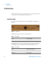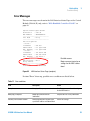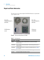
1
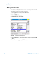
Agilent G1369B
LAN Interface
User Manual
Agilent Technologies
Notices
© Agilent Technologies, Inc. 2010
Warranty
No part of this manual may be reproduced in
any form or by any means (including electronic storage and retrieval or translation
into a foreign language) without prior agreement and written consent from Agilent
Technologies, Inc. as governed by United
States and international copyright laws.
The material contained in this document is provided “as is,” and is subject to being changed, without notice,
in future editions. Further, to the maximum extent permitted by applicable
law, Agilent disclaims all warranties,
either express or implied, with regard
to this manual and any information
contained herein, including but not
limited to the implied warranties of
merchantability and fitness for a particular purpose. Agilent shall not be
liable for errors or for incidental or
consequential damages in connection with the furnishing, use, or performance of this document or of any
information contained herein. Should
Agilent and the user have a separate
written agreement with warranty
terms covering the material in this
document that conflict with these
terms, the warranty terms in the separate agreement shall control.
Manual Part Number
G1369-90001
Edition
05/10
Printed in Germany
Agilent Technologies, Deutschland GmbH
Hewlett-Packard-Strasse 8
76337 Waldbronn
Microsoft ® is a U.S. registered trademark
of Microsoft Corporation.
Software Revision
This guide is valid for A.01.xx revisions of
the Agilent G1369B LAN Interface software,
where xx refers to minor revisions of the
software that do not affect the technical
accuracy of this guide.
defined in FAR 52.227-19(c)(1-2) (June
1987). U.S. Government users will receive
no greater than Limited Rights as defined in
FAR 52.227-14 (June 1987) or DFAR
252.227-7015 (b)(2) (November 1995), as
applicable in any technical data.
Safety Notices
CAUTION
A CAUTION notice denotes a hazard. It calls attention to an operating procedure, practice, or the like
that, if not correctly performed or
adhered to, could result in damage
to the product or loss of important
data. Do not proceed beyond a
CAUTION notice until the indicated
conditions are fully understood and
met.
Technology Licenses
The hardware and/or software described in
this document are furnished under a license
and may be used or copied only in accordance with the terms of such license.
Restricted Rights Legend
If software is for use in the performance of a
U.S. Government prime contract or subcontract, Software is delivered and licensed as
“Commercial computer software” as
defined in DFAR 252.227-7014 (June 1995),
or as a “commercial item” as defined in FAR
2.101(a) or as “Restricted computer software” as defined in FAR 52.227-19 (June
1987) or any equivalent agency regulation or
contract clause. Use, duplication or disclosure of Software is subject to Agilent Technologies’ standard commercial license
terms, and non-DOD Departments and
Agencies of the U.S. Government will
receive no greater than Restricted Rights as
WA R N I N G
A WARNING notice denotes a
hazard. It calls attention to an
operating procedure, practice, or
the like that, if not correctly performed or adhered to, could result
in personal injury or death. Do not
proceed beyond a WARNING
notice until the indicated conditions are fully understood and
met.
G1369B LAN Interface User Manual
In This Guide…
This guide contains information to install the LAN Interface
(G1369B).
1
Introduction - Around your LAN Interface
In this chapter you will find an introduction to the LAN
Interface and its function.
2
Getting Started
In this chapter you will find instructions to help you to set-up
your LAN Interface based on the Agilent 1100/1200/1260 series
HPLC modules.
3
Getting Help
In this chapter you will find support information about
troubleshooting, repair and the Agilent web.
G1369B LAN Interface User Manual
3
4
G1369B LAN Interface User Manual
Contents
Introduction to the LAN Interface 8
Versions of LAN Cards 9
LAN Control - What Exactly Does It Do?
LAN Interface - What Has To Be Done?
LAN Control Configurations 11
LAN Interface Compatibility 13
Installing and Cabling the LAN Interface
What You Will Get 16
What You Have To Do First 17
9
10
16
LAN Interface Configuration 20
TCP/IP Parameter Configuration 20
Configuration Switches 21
Initialization Mode Selection 22
Link Configuration Selection 26
Automatic Configuration with Bootp 27
Configuring the Agilent Bootp Service Program 27
Configuring the CAG Bootp Server Program 31
Storing the Settings Permanently with Bootp Program
Manual Configuration 37
With Telnet 38
With Handheld Controller G1323B
36
43
PC and Agilent ChemStation Setup 48
PC Setup for Local Configuration 48
Agilent ChemStation Setup 49
Troubleshooting 52
Link Status LEDs 52
Error Messages 53
Repair and Parts Information
Firmware Update
G1369B LAN Interface User Manual
54
55
5
Contents
Update Procedure
55
Agilent Support Information 56
Reporting of Problems 56
Agilent Web 56
Glossary
6
57
G1369B LAN Interface User Manual
Agilent G1369B LAN Interface
User Manual
1
Introduction - Around your LAN
Interface
Introduction to the LAN Interface 8
LAN Control - What Exactly Does It Do? 9
LAN Interface - What Has To Be Done? 10
LAN Control Configurations 11
Local Configuration Using Cross-over Cable 11
LAN Using a HUB and Twisted Pair Cables 11
LAN With Existing Customer Network 12
LAN Interface Compatibility 13
In this chapter you will find an introduction to the LAN Interface and its
function.
Agilent Technologies
7
1
Introduction - Around your LAN Interface
Introduction to the LAN Interface
Introduction to the LAN Interface
The LAN Interface (Local Area Network) is the Agilent replacement for the
previously used HP JetDirect card in the Agilent 1100/1200/1260 series HPLC
modules, the 8453 UV-vis spectrophometer, the 35900E A/D converter and the
6850 Series GC.
Figure 1
8
LAN Interface
G1369B LAN Interface User Manual
Introduction - Around your LAN Interface
Introduction to the LAN Interface
1
Versions of LAN Cards
Table 1
NOTE
Product Number
Part Number
Comments
• G1369B
G1369-60002
introduced 03/2010, same features as G1369A,
replaces G1369A, backward compatible
• G1369A
G1369-60001
introduced 10/2003
Compared to the G1369A LAN Card, SW 7 and SW 8 must be always in OFF position on the G1369B
LAN Card, otherwise the selected modes are not working. See “Configuration Switches” on
page 21.
LAN Control - What Exactly Does It Do?
In its simplest form…
• control of your instrument and acquires data “remotely” from your desktop
(easier access),
• a direct replacement for GP-IB (HP-IB) interface protocol,
• allows your instrument to be placed anywhere on the laboratory/corporate
network,
• improves lab “ergonomics” (better organization),
G1369B LAN Interface User Manual
9
1
Introduction - Around your LAN Interface
Introduction to the LAN Interface
LAN Interface - What Has To Be Done?
• install LAN Interface into the instrument
• install network interface card (NIC) into PC (if not already pre-installed or
on-board).
• connect to instrument
• direct with cross-over cable or
• to HUB with twisted pair cable
• configure instrument on LAN
10
G1369B LAN Interface User Manual
Introduction - Around your LAN Interface
Introduction to the LAN Interface
1
LAN Control Configurations
The basic LAN configurations are shown below.
Local Configuration Using Cross-over Cable
The simplest way is a configuration with a single system.
Patch-cable Cross-over
Shielded 3 m (5023-0203)
Figure 2
Local configuration using cross-over cable
LAN Using a HUB and Twisted Pair Cables
More complicated setup than direct cross-over connection.
Patch-cable Twisted pair Shielded
7 m (5023-0202) for all cables
Figure 3
LAN configuration using a HUB and twisted pair cables
G1369B LAN Interface User Manual
11
1
Introduction - Around your LAN Interface
Introduction to the LAN Interface
LAN With Existing Customer Network
Use MDI/MDI-X port or “Cascade” Port with standard twisted pair cable to
connect Hub to a “parent” hub. IP Addresses and other TCP/IP configuration
information MUST be provided by the customer’s IT organization. The
customer LAN must be able to handle instrument data and must have
sufficient bandwidth for instrument acquisition (no overnight backups over
the LAN).
Patch-cable Shielded 7 m
(5023-0202) for all cables
Figure 4
12
LAN configuration with existing customer network
G1369B LAN Interface User Manual
Introduction - Around your LAN Interface
Introduction to the LAN Interface
1
LAN Interface Compatibility
The table below lists the minimum requirements for LAN operation with the
LAN Interface.
Table 2
LAN Compatibility
Instrument/Operating Software
Revision (minimum)
Agilent 1100/1200 modules
Firmware A.03.80 and Revision 2 mainboard, see Table 3
Agilent 1260 Infinity modules
All revisions
Agilent Instant Pilot G4208A
All revsions show the status page, editing is possible, see
Figure 34 on page 45.
Agilent Control Module G1323A
All revsions show just the status page, no editing possible
Agilent Control Module G1323B
All revsions below B.02.02 show just the status page, no
editing possible. With B.02.02 and above editing is possible,
see Figure 34 on page 45.
Agilent 8453 Spectrophotometer
Firmware 3.30
Agilent 35900E A/D converter
requires G1369A board revision Rev. C.03.00 (introduced
04/2005) or G1369B
Agilent 6850 Series GC
requires G1369A board revision Rev. C.03.00 (introduced
04/2005) or G1369B
Agilent Control Module G1818A
No viewing or editing possible
Agilent ChemStation software
A.06.02 or later
G1369B LAN Interface User Manual
13
1
Introduction - Around your LAN Interface
Introduction to the LAN Interface
LAN Compatibility On Early 1100 Modules
All 1100 Series HPLC modules shipped prior to 1997 are NOT compatible with
the LAN Interface communication. The modules which host the LAN Interface
(usually the detector module) requires a new main board. The serial number
break of the 1100 series modules and the part numbers for the new boards are
listed below.
Table 3
14
LAN compatibility on early 1100 modules
1100 Module
S/N break
P/N Mainboard
G1310A
below DE64300355, US64400233
G1311-66520 or higher
G1311A
below DE64301137, US64401134
G1311-66520 or higher
G1312A
below DE64300703, US64400425
G1312-66520 or higher
G1313A
below DE64302092, US64400886
G1313-66520 or higher
G1314A
below JP64201926
G1314-66521 or higher
G1315A
below DE64301532, US64400333
G1315-66520 or higher
G1369B LAN Interface User Manual
Agilent G1369B LAN Interface
User Manual
2
Getting Started
Installing and Cabling the LAN Interface 16
What You Will Get 16
What You Have To Do First 17
LAN Interface Configuration 20
TCP/IP Parameter Configuration 20
Configuration Switches 21
Initialization Mode Selection 22
Using Stored 24
Using Default 24
Bootp 22
Bootp & Store 23
Link Configuration Selection 26
Automatic Configuration with Bootp 27
Configuring the Agilent Bootp Service Program 27
Configuring the CAG Bootp Server Program 31
Storing the Settings Permanently with Bootp Program 36
Manual Configuration 37
With Telnet 38
With Agilent Instant Pilot 42
With Handheld Controller G1323B 43
PC Setup for Local Configuration 48
Agilent ChemStation Setup 49
In this chapter you will find instructions to help you to set-up your LAN
Interface based on the Agilent 1100/1200/1260 series HPLC modules.
Agilent Technologies
15
2
Getting Started
Installing and Cabling the LAN Interface
Installing and Cabling the LAN Interface
What You Will Get
• G1369B LAN Interface
• LAN cables (for part numbers see “Repair and Parts Information” on
page 54)
Patch-cable
Twisted pair Shielded 7 m
(5023-0202)
Patch-cable
Cross-over Shielded 3 m
(5023-0203)
CD-ROM with the
manual
LAN Interface
(G1369-60002)
Figure 5
16
What you will get (Content of G1369B)
G1369B LAN Interface User Manual
Getting Started
Installing and Cabling the LAN Interface
2
What You Have To Do First
NOTE
Use an ESD (Electro-Static Discharge) wrist strap when handling electronics. Refer to your
instrument manual for details.
1 Remove the LAN Interface from it’s packaging.
Configuration switch,
see “Configuration
Switches” on
MAC label, see
Figure 7 on page 18
Board information
(manufacturing part
number, revision)
Figure 6
Board Layout G1369B
G1369B LAN Interface User Manual
17
2
Getting Started
Installing and Cabling the LAN Interface
2 Note the MAC (Media Access Control) address for further reference. The
MAC or hardware address of the LAN Interface is a world wide unique
identifier. No other network device will have the same hardware address.
The MAC address can be found on a label on the card (see Figure 6 on
page 17).
G1369-61800
BB ZZ 1003 MSS-A
MAC 0030D3177321
Made in Germany
Figure 7
Part number of the LAN Interface, see page 54
Revision Code, Vendor, Year and Week of assembly
MAC address
Country of Origin
MAC-Label
3 Turn off instrument line power or remove the power cord before installing
the LAN Interface.
4 On your instrument, identify the option slot for the MIO accessory card.
5 Remove any blank cover plates and ensure that the slot is empty.
NOTE
If the module has the 1100 CAN modification board installed, it probably has a revision 1
mainboard and will not accept the LAN interface. Refer to “LAN Interface Compatibility” on
page 13
Figure 8
18
Location of LAN Interface (e.g. 1100/1200 series detector)
G1369B LAN Interface User Manual
Getting Started
Installing and Cabling the LAN Interface
2
NOTE
In 1100/1200/1260 systems, the LAN Interface should be installed in the detector (DAD,
MWD, FLD, VWD) due to its higher data handling rate. If no 1100/1200/1260 detector
available, use the pump or the autosampler (in this order).
NOTE
The LAN Interface is shipped with the Bootp initialization mode and will use the
parameters (IP, Subnet Mask and Default Gateway addresses) from a Bootp server. If you
need another initialization mode or other settings, refer to “Initialization Mode
Selection” on page 22 for details before doing the next step.
6 Carefully slide the LAN Interface into the slot. Some pressure may be
necessary to properly seat the board. Tighten the screws.
7 Disconnect your PC from the network and connect the PC network card to
the instrument's LAN Interface using a Crossover Network cable
(point-to-point) or alternatives, see page 11 and page 12.
CAUTION
Be careful that you connect the LAN cable to the LAN Interface and NOT one of the CAN
connections. The CAN bus uses 12-Volt signals, and a misconnection to the CAN bus may
destroy network equipment on the other end of the cable.
LAN
comunication only
CAN for
inter-module
communication
only
Figure 9
Connect the LAN cable to the correct connector
G1369B LAN Interface User Manual
19
2
Getting Started
LAN Interface Configuration
LAN Interface Configuration
TCP/IP Parameter Configuration
To operate properly in a network environment, the LAN Interface must be
configured with valid TCP/IP network parameters. These parameters are:
• IP address
• Subnet Mask
• Default Gateway
The TCP/IP parameters can be configured by the following methods:
• by automatically requesting the parameters from a network-based BOOTP
Server (using the so-called Bootstrap Protocol)
• by manually setting the parameters using Telnet
• by manually setting the parameters using the Agilent Instant Pilot
(G4208A)
• by manually setting the parameters using the Handheld Controller
(G1323A/B)
The LAN Interface differentiates between several initialization modes. The
initialization mode (short form ‘init mode’) defines how to determine the
active TCP/IP parameters after power-on. The parameters may be derived
from a Bootp cycle, non-volatile memory or initialized with known default
values. The initialization mode is selected by the configuration switch, see
Figure 10 on page 21.
20
G1369B LAN Interface User Manual
Getting Started
LAN Interface Configuration
2
Configuration Switches
The configuration switches are mounted on the card, see Figure 10.
ON
1
2
3
4
5
6
7
8
Figure 10
Location of Configuration Switches
The LAN Interface is shipped with all switches set to OFF, as shown above.
Table 4
NOTE
Factory Default Settings
Initialization (‘Init’) Mode
Bootp, for details see page 22
Link Configuration
speed and duplex mode determined by auto-negotiation, for
details see page 26
Compared to the G169A LAN Card, SW 7 and SW 8 must be always in OFF position on the G1369B
LAN Card, otherwise the selected modes are not working.
G1369B LAN Interface User Manual
21
2
Getting Started
LAN Interface Configuration
Initialization Mode Selection
The following initialization (init) modes are selectable:
Table 5
Initialization Mode Switches
SW 4
SW 5
SW 6
SW 7
SW 8
Init Mode
OFF
OFF
OFF
OFF
OFF
Bootp
OFF
OFF
ON
OFF
OFF
Bootp & Store
OFF
ON
OFF
OFF
OFF
Using Stored
OFF
ON
ON
OFF
OFF
Using Default
ON
1
NOTE
2
3
4
5
6
7
8
Compared to the G169A LAN Card, SW 7 and SW 8 must be always in OFF position on the G1369B
LAN Card, otherwise the selected modes are not working.
Bootp
When the initialization mode “Bootp” is selected, the card tries to download
the parameters from a Bootp Server. The parameters obtained become the
active parameters immediately. They are not stored to the non-volatile
memory of the card. Therefore, the parameters are lost with the next power
cycle of the card.
Bootp
Server
Figure 11
22
Active
Parameter
Bootp (Principle)
G1369B LAN Interface User Manual
Getting Started
LAN Interface Configuration
2
Bootp & Store
When “Bootp & Store” is selected, the parameters obtained from a Bootp
Server become the active parameters immediately. In addition, they are stored
to the non-volatile memory of the card. Thus, after a power cycle they are still
available. This enables a kind of “bootp once” configuration of the card.
Example: The user may not want to have a Bootp Server be active in his
network all the time. But on the other side, he may not have any other
configuration method than Bootp. In this case he starts the Bootp Server
temporarily, powers on the card using the initialization mode “Bootp &Store”,
waits for the Bootp cycle to be completed, closes the Bootp Server and powers
off the card. Then he selects the initialization mode “Using Stored” and powers
on the card again. From now on, he is able to establish the TCP/IP connection
to the card with the parameters obtained in that single Bootp cycle.
Bootp
Server
Active
Parameter
Non-Volatile
RAM
Stored
Parameter
Figure 12
NOTE
Bootp & Store (Principle)
Use the initialization mode “Bootp & Store” carefully, because writing to the non-volatile
memory takes time. Therefore, when the card shall obtain its parameters from a Bootp
Server every time it is powered on, the recommended initialization mode is “Bootp”!
G1369B LAN Interface User Manual
23
2
Getting Started
LAN Interface Configuration
Using Stored
When initialization mode “Using Stored” is selected, the parameters are taken
from the non-volatile memory of the card. The TCP/IP connection will be
established using these parameters. The parameters were configured
previously by one of the described methods.
Non-Volatile
RAM
Active
Parameter
Stored
Parameter
Figure 13
Using Stored (Principle)
Using Default
When “Using Default” is selected, the factory default parameters are taken
instead. These parameters enable a TCP/IP connection to the LAN Interface
without further configuration, see Table 6.
Active
Parameter
Default
Parameter
Figure 14
NOTE
Using the default address in your local area network may result in network problems. Take
care and change it to a valid address immediately.
Table 6
24
Using Default (Principle)
Using Default Parameters
IP address:
192.168.254.11
Subnet Mask:
255.255.255.0
Default Gateway
not specified
G1369B LAN Interface User Manual
Getting Started
LAN Interface Configuration
2
Since the default IP address is a so-called local address, it will not be routed by
any network device. Thus, the PC and the card must reside in the same subnet.
The user may open a Telnet session using the default IP address and change
the parameters stored in the non-volatile memory of the card. He may then
close the session, select the initialization mode “Using Stored”, power-on again
and establish the TCP/IP connection using the new parameters.
When the card is wired to the PC directly (e.g. using a cross-over cable or a
local hub), separated from the local area network, the user may simply keep
the default parameters to establish the TCP/IP connection.
NOTE
In the “Using Default” mode, the parameters stored in the memory of the card are not
cleared automatically. If not changed by the user, they are still available, when switching
back to the mode “Using Stored”.
G1369B LAN Interface User Manual
25
2
Getting Started
LAN Interface Configuration
Link Configuration Selection
The LAN Interface supports 10 or 100 Mbps operation in full- or half-duplex
modes. In most cases, full-duplex is supported when the connecting network
device - such as a network switch or hub - supports IEEE 802.3u
auto-negotiation specifications.
When connecting to network devices that do not support auto-negotiation, the
LAN Interface will configure itself for 10- or 100-Mbps half-duplex operation.
For example, when connected to a non-negotiating 10-Mbps hub, the LAN
Interface will be automatically set to operate at 10-Mbps half-duplex.
If the card is not able to connect to the network through auto-negotiation, you
can manually set the link operating mode using link configuration switches on
the card.
Table 7
Link Configuration Switches
SW 1
SW 2
SW 3
SW 7
SW 8
Link Configuration
OFF
-
-
OFF
OFF
speed and duplex mode determined by
auto-negotiation
ON
OFF
OFF
OFF
OFF
manually set to 10 Mbps, half-duplex
ON
OFF
ON
OFF
OFF
manually set to 10 Mbps, full-duplex
ON
ON
OFF
OFF
OFF
manually set to 100 Mbps, half-duplex
ON
ON
ON
OFF
OFF
manually set to 100 Mbps, full-duplex
ON
1
2
3
NOTE
26
4
5
6
7
8
Compared to the G169A LAN Card, SW 7 and SW 8 must be always in OFF position on the G1369B
LAN Card, otherwise the selected modes are not working.
G1369B LAN Interface User Manual
Getting Started
Automatic Configuration with Bootp
2
Automatic Configuration with Bootp
When automatic configuration with Bootp is selected and the LAN Interface is
powered on, it broadcasts a BOOTP (Bootstrap Protocol) request that contains
its MAC (hardware) address. A BOOTP server daemon searches its database
for a matching MAC address, and if successful, sends the corresponding
configuration parameters to the card as a BOOTP reply. These parameters
become the active TCP/IP parameters immediately and the TCP/IP connection
can be established.
Configuring the Agilent Bootp Service Program
NOTE
All examples shown in this chapter will not work in your environment. You
need your own IP-, Subnet-Mask- and Gateway addresses.
NOTE
Assure that the detector configuration switch is set properly. The setting
should be either Bootp or Bootp & Store, see Table 5 on page 22.
NOTE
Assure that the detector connected to the network is powered off.
NOTE
If the Agilent Bootp Service program is not already installed on your PC, then install it from
your Agilent ChemStation CD-ROM, located in folder \Bootp. The screens refer to version
B.01.0x
G1369B LAN Interface User Manual
27
2
Getting Started
Automatic Configuration with Bootp
1 The Agilent Bootp Service is placed in the start-up group and automatically
is started during the boot process of the PC.
2 Open the Bootp Settings window (Figure 15) and enter the default settings
for your setup.
location of LogFile and TabFile
Figure 15
Bootp Service Settings
3 Launch the Manager. It will open the Bootp Manager screen, see Figure 16.
This shows all network hardware that has been added (initially empty).
Figure 16
28
Bootp Manager
G1369B LAN Interface User Manual
Getting Started
Automatic Configuration with Bootp
2
4 Select Add to enter the enter the module specific information, see
Figure 17:
• MAC address (from label on the instrument)
• host name
• IP address
• comment (instrument name / location)
• subnet mask (if different)
• gateway (if required)
Figure 17
Bootp Manager - Enter your parameter
G1369B LAN Interface User Manual
29
2
Getting Started
Automatic Configuration with Bootp
5 Press OK. The parameter are added to the Bootp Manager, see Figure 17
and added to the TabFile, see Figure 15 on page 28:
Figure 18
Bootp Manager - check your entries
6 Press Exit Manager and OK to exit the Agilent Bootp Service.
7 Now turn on the module with the detector, wait about 30-60 seconds and
view the LogFile, see Figure . It should display the request from the
detector with the hardware (MAC) address.
02/03/05 16:33:56 PM
Status: BOOTP Request received at outer most layer
Status: BOOTP Request received from hardware address: 0030D30A0838
Status: found 134.40.27.95 WADI1171:
Status: Host IP Address is: 134.40.29.56
Status: Reply to BOOTP Request has been sent
Status: BOOTP Request finished processing at outer most layer
LogFile - the detector has received the parameter
30
G1369B LAN Interface User Manual
Getting Started
Automatic Configuration with Bootp
NOTE
2
When using this Bootp mode, the parameters are not written into the non-volatile memory
of the detector. If you delete this Bootp Configuration, the Bootp Manager will show up as
shown in Figure 16 on page 28 (Bootp mode).
If you want to store your parameters permanently on the detector (for use without the
Agilent Bootp service), refer to “Storing the Settings Permanently with Bootp Program” on
page 36.
Configuring the CAG Bootp Server Program
NOTE
All examples shown in this chapter will not work in your environment. You
need your own IP-, Subnet-Mask- and Gateway addresses.
NOTE
Assure that the LAN Interface configuration switch is set properly. The setting
should be either Bootp or Bootp & Store, see Table 5 on page 22.
NOTE
Assure that the instrument with the LAN Interface installed and connected to the PC is
powered off.
NOTE
If the CAG Bootp Server program is not already installed on your PC, then install it from your
Agilent ChemStation CD-ROM, located in folder \Bootp.
1 The CAG Bootp Server program is placed in the start-up group and
automatically is started during the boot process of the PC. It’s minimized
and located in the task bar.
2 Open the Bootp Server window by clicking on it in the task bar.
3 Now turn on the module with the LAN Interface and view the Bootp Server
window. After some time the Bootp Server will display the request from the
LAN Interface with the hardware (MAC) address (this information is also
stored in the file trace.txt in the bootp server directory, if Log to Disk is
enabled), see Figure 19 on page 32.
The MAC or hardware address of the LAN Interface is a world wide unique
identifier. No other network device will have the same hardware address.
The MAC address can be found on a label on the card, see Figure 6 on
page 17.
G1369B LAN Interface User Manual
31
2
Getting Started
Automatic Configuration with Bootp
Figure 19
Bootp Server
4 Identify your LAN Interface by the MAC address, see Figure 19.
NOTE
If you are working in a network system, you may see other LAN Interfaces appear,
overwriting your LAN Interface information periodically.
5 Select Configure -> Add Entry to configure the Bootp Manager (Figure 21).
The drop down box “MAC address” lists all MAC addresses found. Select
your MAC address. If no hardware address is found, select Cancel and
repeat step 3 and step 4.
Figure 20
32
Add Bootp Entry - Select the MAC address
G1369B LAN Interface User Manual
Getting Started
Automatic Configuration with Bootp
2
6 Specify the Host Name (LC1100-01), the IP address (134.40.24.230), the
Comment (LC1100-01) and the Subnet Mask 255.255.248.0 and the Gateway
(134.40.24.1).
NOTE
If you are working in a network system, you need your own addresses. Contact your local IT
group.
Figure 21
Add Bootp Entry - Enter your parameter
7 Exit with OK.
8 Select Configure -> Bootp Manager. All entries made above are shown in
Figure 22 on page 34.
G1369B LAN Interface User Manual
33
2
Getting Started
Automatic Configuration with Bootp
Figure 22
Bootp Manager
9 Press Apply to activate the changes.
10 Press OK to exit the Bootp Manager and power cycle the instrument with
the LAN Interface, to force it to send a new bootp request again. This time,
the MAC address will be recognized by the Bootp Server (Figure 23). It will
send the configured IP address and subnet mask information which are
necessary for communication to the LAN Interface.
IP address LAN
Interface is
134.40.24.230
IP address PC is
134.40.30.184
Figure 23
34
Bootp Server - module found
G1369B LAN Interface User Manual
Getting Started
Automatic Configuration with Bootp
NOTE
2
When using this Bootp mode, the parameters are not written into the non-volatile memory
of the card. If you delete this Bootp Configuration, the LAN Interface will show up as shown
in Figure 19 on page 32 (Bootp mode).
If you want to store your parameters permanently on the card (for use without the CAG
Bootp server), refer to “Storing the Settings Permanently with Bootp Program” on page 36.
G1369B LAN Interface User Manual
35
2
Getting Started
Storing the Settings Permanently with Bootp Program
Storing the Settings Permanently with Bootp Program
If you want to change parameters of the card using the Bootp follow the
instructions below.
NOTE
Use an ESD (Electro-Static Discharge) wrist strap when handling electronics. Refer to your
instrument manual for details.
1 Turn off the module that hosts the LAN Interface and remove the card.
2 Change the card’s settings of the Configuration Switch to ”Bootp & Store”
mode, see Table 5 on page 22.
3 Install the LAN Interface.
4 Start the CAG Bootp Server program and open its window.
5 If required, modify the parameters for the LAN Interface according to your
needs using the existing configuration.
6 Press OK to exit the Bootp Manager.
7 Now turn on the module with the LAN Interface and view the Bootp Server
window. After some time the Bootp Server will display the request from the
LAN Interface. The parameters are now stored permanently in the
non-volatile memory of the card.
8 Close the CAG Bootp Server program and turn off the module and remove
the LAN Interface.
9 Change the settings of the card’s Configuration Switch to “Using Stored”
mode, see Table 5 on page 22.
10 Install the card and power cycle the module with the LAN Interface. The
card can be accessed now via LAN without the CAG Bootp Server program,
refer to “PC and Agilent ChemStation Setup” on page 48.
36
G1369B LAN Interface User Manual
Getting Started
Manual Configuration
2
Manual Configuration
Manual configuration only alters the set of parameters stored in the
non-volatile memory of the card. It never affects the currently active
parameters. Therefore, manual configuration can be done at any time. A
power cycle is mandatory to make the stored parameters become the active
parameters, given that the initialization mode selection switches are allowing
it.
TELNET
Session
Non-Volatile
RAM
Stored
Parameter
Control Module
Figure 24
Manual Configuration (Principle)
G1369B LAN Interface User Manual
37
2
Getting Started
Manual Configuration
With Telnet
Whenever a TCP/IP connection to the card is possible (TCP/IP parameters set
by any method), the parameters may be altered by opening a Telnet session.
1 Open the system (DOS) prompt window by clicking on Windows START
button and select “Run...”. Type “cmd” and press OK.
2 Type the following at the system (DOS) prompt:
c:\>telnet <IP address>
Figure 25
Telnet - Starting a session
where <IP address> may be the assigned address from a Bootp cycle, a
configuration session with the Agilent Instant Pilot (G4208A) or Handheld
Controller (G1323A/B), or the default IP address (see “Configuration
Switches” on page 21).
When the connection was established successfully, the card responds with
the following:
Figure 26
A connection to the module is made
3 To change a parameter follows the style:
parameter value
for example: ip 134.40.24.230
38
G1369B LAN Interface User Manual
Getting Started
Manual Configuration
2
then press [Enter], where parameter refers to the configuration parameter
you are defining, and value refers to the definitions you are assigning to
that parameter. Each parameter entry is followed by a carriage return.
Table 8
NOTE
Telnet Commands
Value
Description
?
displays syntax and descriptions of commands
/
displays current settings
ip <x.x.x.x>
sets new ip address
sn <x.x.x.x>
set new subnet mask
gw <x.x.x.x>
sets new default gateway
quit
saves changes and exit shell
exit
exits shell without saving changes
Any time during the Telnet session you can type “?” then press [Enter] to view available
configuration parameters, the correct command format, and a list of additional commands
to display.
G1369B LAN Interface User Manual
39
2
Getting Started
Manual Configuration
4 Use the “/” and press Enter to list the current settings.
information about the card
Product id, firmware revision (A.xx.xx are released
versions), MAC address, initialization mode
Initialization mode is Bootp
The connected PC/Bootserver is 134.40.24.184
active TCP/IP settings
stored TCP/IP settings in non-volatile memory (not
visible if equal to active TCP/IP settings)
connected to PC with controller software (e.g. Agilent
ChemStation), here not connected
Figure 27
Telnet - Current settings in Bootp mode
5 Change the IP address (in this example 134.40.24.158) and type “/” to list
current settings.
change of TCP/IP setting
Initialization mode is Bootp
The connected PC/Bootserver is 134.40.24.184
active TCP/IP settings
stored TCP/IP settings in non-volatile memory
last user change (not active yet, requires mode “Using
Stored” and re-start)
40
G1369B LAN Interface User Manual
Getting Started
Manual Configuration
Figure 28
2
Telnet - Change IP settings
6 When you have finished typing the configuration parameters, type:
quit and press [Enter] to store the configuration parameters
or
exit and press [Enter] to exit without storing parameters.
If the Initialization Mode Switch is changed now to “Using Stored” mode,
the instrument will take the stored settings when the module is re-booted.
In the example above it would be 134.40.24.158 on QUIT and 134.40.24.160
on EXIT.
G1369B LAN Interface User Manual
41
2
Getting Started
Manual Configuration
With Agilent Instant Pilot
To configure the TCP/IP parameters before connecting the detector to the
network, the Instant Pilot (G4208A) can be used.
1 From the Welcome screen press the More button.
2 Select Configure.
3 Press the DAD (MWD) button.
4 Scroll down to the LAN settings.
Figure 29
Instant Pilot - LAN Configuration
5 Press the Edit button, perform the required changes and press the Done
button.
6 Leave the screen by pressing the Exit button.
42
G1369B LAN Interface User Manual
Getting Started
Manual Configuration
2
With Handheld Controller G1323B
To configure the TCP/IP parameters before connecting the card to the
network, the Handheld Controller (G1323B with firmware B.02.02 or above
for 1100/1200 series modules only, see “LAN Interface Compatibility” on
page 13) can be used.
1 Press F5 “Views”, select “System” and press the “Enter” key.
2 Press F2 “Configure”, select the module where the LAN Interface is
installed and press the “Enter” key (Figure 30).
Figure 30
Select module
3 Press F1 “Interfaces”, select “MIO” and press the “Enter” key (Figure 31).
Figure 31
Select MIO
G1369B LAN Interface User Manual
43
2
Getting Started
Manual Configuration
4 A Warning message shall pop up. Press “Continue” (Figure 32).
Figure 32
Warning message
5 After the Handheld Controller was reading out the LAN Interface you will
get an overview of all the parameters that are set in the card (LAN Interface
Status Page). The information corresponds to the information in Figure 27
on page 40.
Figure 33
LAN Interface Status Page
In Figure 34 on page 45 the complete listing is shown. For explanations refer
to Figure 27 on page 40.
44
G1369B LAN Interface User Manual
Getting Started
Manual Configuration
2
Agilent Technologies G1369B
FW Revision
: A.01.01
MAC Address
: 0030d3060122
-------------------------------Init Mode
: Bootp
Bootp Server : 134.40.30.184
-------------------------------TCP/IP Properties
- active IP Address
: 134.40.24.230
Subnet Mask
: 255.255.248.0
Def. Gateway : 134.40.24.1
- stored IP Address
: 134.40.24.160
Subnet Mask
: 255.255.248.0
Def. Gateway : 134.40.24.1
-------------------------------TCP/IP Status : Ready
-------------------------------Controller
: not connected
Figure 34
LAN Interface Status Page (complete)
6 To change the TCP/IP settings, press F1 “Service”.
Figure 35
Entering the Service Mode
G1369B LAN Interface User Manual
45
2
Getting Started
Manual Configuration
Figure 36
TCP/IP parameters
7 Move to the parameter you want to change, enter the new value and press
“Enter”.
Figure 37
46
Service
G1369B LAN Interface User Manual
Getting Started
Manual Configuration
2
8 If you completed your changes, press “Done” to leave the Service section.
9 Press F6 “Done” and restart the module by pressing “OK” .
Figure 38
Re-boot screen
G1369B LAN Interface User Manual
47
2
Getting Started
PC and Agilent ChemStation Setup
PC and Agilent ChemStation Setup
PC Setup for Local Configuration
This procedure describes the change of the TCP/IP settings on your PC to
match the LAN Interface default parameters in a local configuration (see also
“Local Configuration Using Cross-over Cable” on page 11 and “Using
Default” on page 24).
Figure 39
48
Changing the TCP/IP settings of the PC
G1369B LAN Interface User Manual
Getting Started
PC and Agilent ChemStation Setup
2
Agilent ChemStation Setup
1 Start the Configuration Editor of the Agilent ChemStation.
Figure 40
Changing the TCP/IP settings of the Agilent ChemStation
2 Add a TCP/IP connection to communicate with the LAN Interface. Use the
IP address of the LAN Interface.
NOTE
If using a corporate LAN, IP addresses need to be supplied by the responsible IT
department. Also the LAN needs to be able to handle additional traffic.
3 Save the configuration, close the Configuration Editor and start the Agilent
ChemStation.
G1369B LAN Interface User Manual
49
2
50
Getting Started
PC and Agilent ChemStation Setup
G1369B LAN Interface User Manual
Agilent G1369B LAN Interface
User Manual
3
Getting Help
Troubleshooting 52
Link Status LEDs 52
Error Messages 53
Repair and Parts Information 54
Firmware Update 55
Agilent Support Information 56
Reporting of Problems 56
Agilent Web 56
Glossary 57
In this chapter you will find support information about troubleshooting,
repair and the Agilent web.
Agilent Technologies
51
3
Getting Help
Troubleshooting
Troubleshooting
If the LAN Interface does not successfully connect to the network, there are
several ways to get status information from the card.
Link Status LEDs
On the card, near the RJ-45 connector, two status LEDs are mounted. See
Figure 41.
Figure 41
Status LEDs
The LED named “Speed” shows the actual link speed.
Table 9
LED “Speed”
LED off
link speed 10 Mbps
LED on
link speed 100 Mbps
The LED named “Activity” shows whether the physical link is established or
not. In addition, it shows whether the card is transferring data or not.
Table 10
52
LED “Activity”
LED off
no physical link established
LED on
physical link established
LED blinking
transferring data
G1369B LAN Interface User Manual
Getting Help
Troubleshooting
3
Error Messages
The error messages are shown in the LAN Interface Status Page on the Control
Module (G1323A/B) only, refer to “With Handheld Controller G1323B” on
page 43.
Agilent Technologies G1369B
FW Revision
: A.01.01
MAC Address
: 0030d3060122
-------------------------------Init Mode
: Bootp
-------------------------------TCP/IP Properties
- active IP Address
: 0.0.0.0
Subnet Mask
: not specified
Def. Gateway : not specified
- stored IP Address
: 134.40.24.160
Subnet Mask
: 255.255.248.0
Def. Gateway : 134.40.24.1
-------------------------------TCP/IP Status : Error
Bootp timeout
-------------------------------Controller
: not connected
Figure 42
Possible reasons:
Bootp server not started or no
settings for this MAC address
found
LAN Interface Status Page (complete)
If status "Error" shows up, possible error conditions are listed below.
Table 11
Error conditions
Error
Description
Action
Bootp timeout
No reply on Bootp request received
Start Bootp server and/or add settings
for the LAN Interface.
Bootp reply incomplete
Bootp reply contained not all
information
Complete the neccessary information
Gateway in unreachable network
Default Gateway does not match the
specified IP address and Subnet Mask
Correct the settings
G1369B LAN Interface User Manual
53
3
Getting Help
Repair and Parts Information
Repair and Parts Information
The repair level of the product Agilent G1369B LAN Interface is replacement
of the complete board.
Patch-cable
Twisted pair Shielded 7 m
(5023-0202)
Patch-cable
Cross-over Shielded 3 m
(5023-0203)
CD-ROM with the
manual
LAN Interface
(G1369-60002)
Figure 43
Table 12
54
What you will get (Content of G1369B)
Order information
Order number
Description
G1369B
complete product, Agilent G1369B LAN Interface (includes CD-ROM with
electronic manual)
G1369-60002
same as G1369B. The board G1369-61800 is a manufacturing number only and
cannot be ordered.
G1369-90001
The actual manual as PDF file is available via the Agilent web only, see “Agilent
Web” on page 56
5023-0203
Cross-over (point-to-point) network cable (shielded, 3 m long)
5023-0202
Twisted pair network cable (shielded, 7 m long)
G1369B LAN Interface User Manual
Getting Help
Firmware Update
3
Firmware Update
The LAN Interface’s firmware can be updated, using the firmware provided by
the Agilent support web side. A procedure will be provided with the firmware.
The G1369B LAN card does not take the firmware of the G1316A LAN card
and vice versa. An error message will show up.
Load of G1369A firmware into G1369B LAN card
Figure 44
Load of G1369B firmware into G1369A LAN card
Error when using wrong firmware
Update Procedure
1 Download the actual firmware from the Agilent web
http://www.chem.agilent.com/scripts/cag_firmware.asp?nmod=LC
2 The zipped firmware archive contains all required files and the procedure
for the update.
3 Follow the provided instructions.
G1369B LAN Interface User Manual
55
3
Getting Help
Agilent Support Information
Agilent Support Information
Reporting of Problems
If the LAN Interface shows problems in your system report it with the
following information (from the MAC-Label, see Figure 8 on page 18):
• Part number of the LAN Interface
• Board Revision Code, Vendor, Year and Week of assembly
• MAC address
• Installed firmware revision (if known or still accessable, see Figure 27 on
page 40 or Figure 42 on page 53).
Agilent Web
Latest documentation or firmware updates for this product (Agilent G1369B
LAN Interface) can be obtained from the Agilent web side
http://www.agilent.com
> Life Sciences/Chemical Analysis
For firmware select “Technical Support”, then look for “Firmware for LC &
LC/MS”
For manual select “Library”, then search for G1369B and “manual”
56
G1369B LAN Interface User Manual
Getting Help
Glossary
3
Glossary
Table 13
Glossary
Term / Acronym
Definition
10/100Base-TX
Twisted pair Ethernet cable.
Bootp
Bootstrap Protocol, an Internet protocol that enables a diskless
workstation to discover its own IP address
CAN
Controller Area Network; a shared broadcast bus, which runs at
speeds up to 1Mbit/sec; it is a serial data communications bus
for real-time applications.
CAG
Chemical Analysis Group (Agilent term)
DOS
Disk Operating System. The term DOS can refer to any operating
system, but it is most often used as a shorthand for MS-DOS
(Microsoft disk operating system).
ESD
Electrostatic discharge, the rapid discharge of static electricity
from one conductor to another of a different potential. An
electrostatic discharge can damage integrated circuits
Ethernet
A local area network (LAN) specified as IEEE 802.3
Gateway
A node on a network that serves as an entrance to another
network.
HP-IB or GP-IB
The IEEE-488 Interface Bus (HP-IB) or general purpose interface
bus (GP-IB) was developed to provide a means for various
instruments and devices to communicate with each other under
the direction of one or more master controllers. The HP-IB was
originally intended to support a wide range of instruments and
devices, from the very fast to the very slow.
IP address
An identifier for a computer or device on a TCP/IP network.
Host
A computer system that is accessed by a user working at a
remote location.
Hub
Is some kind of router, which allows clients to connect each
other.
LAN
Lab Area Network
G1369B LAN Interface User Manual
57
3
Getting Help
Glossary
Table 13
58
Glossary
Term / Acronym
Definition
LED
Light Emitting Diode
MAC address
Media Access Control address, a hardware address that
uniquely identifies each node of a network.
MIO
Modular Input/Output; interface specification from
Hewlett-Packard
RJ-45 connector
Registered Jack-45, an eight-wire connector used commonly to
connect computers onto a local-area networks (LAN), especially
Ethernets. RJ-45 connectors look similar to the RJ-11
connectors used for connecting telephone equipment, but they
are somewhat wider.
Subnet Mask
A mask used to determine what subnet an IP address belongs
to. Subnetting enables the network administrator to further
divide the host part of the address into two or more subnets.
TCP/IP
Transmission Control Protocol/Internet Protocol; LAN
(Ethernet) protocol
Telnet
A terminal emulation program for TCP/IP networks such as the
Internet.
G1369B LAN Interface User Manual
www.agilent.com
In This Book
This guide contains
information to install the
LAN Interface (G1369B).
• Introduction - Around your
LAN Interface
• Getting Started
• Getting Help
©
Agilent Technologies, Deutschland GmbH 2010
Printed in Germany
05/10
*G1369-90001*
*G1369-90001*
G1369-90001
Agilent Technologies
www.agilent.com
©
Agilent Technologies, Deutschland GmbH 2010
Printed in Germany
05/10
*G1369-90001*
*G1369-90001*
G1369-90001
Agilent Technologies
www.agilent.com
©
Agilent Technologies, Deutschland GmbH 2010
Printed in Germany
05/10
*G1369-90001*
*G1369-90001*
G1369-90001
Agilent Technologies