1
AMEX Research Corporation Technologies
Modular Development Platform User’s Guide
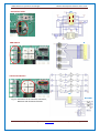
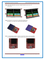
During the display programming (by means of 4D Programming Cable) the power supply is drawn
from USB interface. The change of power supply source is done automatically (from DC regulator on
the board to one delivered by USB cable). There is no need to use SW1 switch. SW1 switch does
disconnect +5V voltage from USB interface. Only disconnection of the cable from J7 connector will
turn off the power supply drawn from USB.
NOTE: Improper connection of programming cable (due to reversal plugging or displacement of
terminals) will damage the display. The main power supply for the board should be switched off
during installation of the display.
Detailed instruction concerning the displays programming can be found in their datasheets at 4D
Systems website www.4dsystems.com.au.
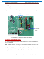
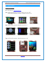
The µLCD-24PTU, µLCD-28PTU, µLCD-32PTU, µLCD32WPTU displays
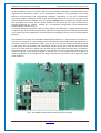
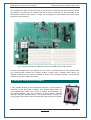
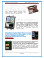
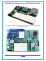
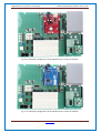
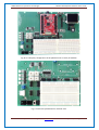
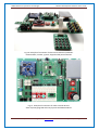
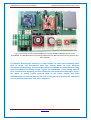
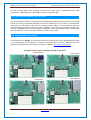
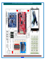
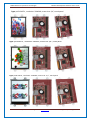
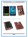
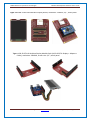
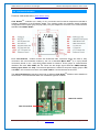
The µLCD-24/28/32/32WPTU display module are installed in vertical direction on 10 and 30 terminal
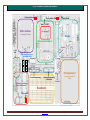
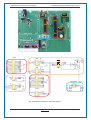
female connectors J19 and J21 on the platform. The signals available in display connector are routed
to J6 male connector placed at upper part of the breadboard and also to 30 terminal J20 connector.
NOTE: terminal No. 10 in J6 provides 3.3V power not from display module but from 3.3V regulator
on the board which can provide higher power,
During the display programming (by means of 4D Programming Cable) the power supply is drawn
from USB interface. The change of power supply source is done automatically (from DC regulator on
the board to one delivered by USB cable). There is no need to use SW1 switch. SW1 switch does
disconnect +5V voltage from USB interface. Only disconnection of the cable from J7 connector will
turn off the power supply drawn from USB.
NOTE: Improper connection of programming cable (due to reversal plugging or displacement of
terminals) will damage the display. The main power supply for the board should be switched off
during installation of the display.
Detailed instruction concerning the displays programming can be found in their datasheets at 4D
Systems website www.4dsystems.com.au.
5.5. The loudspeaker – generating the sounds (Fig. 13, 18, 21)
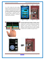
The µOLED-96/128/160-G2 and µLCD-144-G2, µLCD-24/28/32/32WPTU displays have the ability to
generate advanced sounds and music. The audio signals for these purposes are available at
additional terminals in display connector. To connect audio signal to speaker circuit you must use a
jumper in J24 connector to select AUD pin. More information is available in chapter 5.10.
AMEX Research Corporation Technologies
www.amex.pl
e-mail: [email protected]
Page 19 of 55