1
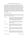
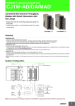
AMEX Research Corporation Technologies
Modular Development Platform User’s Guide
Modular Development Platform
For education of embedded systems
and robotics
USER'S GUIDE
Document Date: 12 August 2013
Document Revision: 1.0
AMEX Research Corporation Technologies
www.amex.pl
e-mail: [email protected]
Page 1 of 55
AMEX Research Corporation Technologies
Modular Development Platform User’s Guide
Contents
1. Introduction….…………………………………………………………………………………………....................3
2. Features……………………….…………………………………………………………………..……………..............3
3. Hardware Description……………………………….…………….………………………………….……………...5
4. Hardware configuration examples……………….…………………………….……….….………………….7
5. Connectors and Modules on the Modular Development Platform………………………….16
5.1. DC Power Supply…………………………………………………………….………….…………………..16
5.2. Servo Power Supply………………………………………………………..….…………………………..16
5.3. Microcontroller Module…………………………………………………..................................17
5.4. Display Module……….………………………………………………………………………………………17
5.5. The loudspeaker – generating the sounds ………………………………………….......19
5.6. Joystik – 5 position switch……..……………………………………………………………………….20
5.7. Prototyping PC field……………………………………………..…………………………………………20
5.8. Breadboard…………………...……………………………………..………………………………………..20
5.9. Conectors field for external devices………..…………..…………………..……………………..20
5.10. Additional devices for Development Platform……………..………………………………….21
6. Accompanying Modules…………………………………………………………….………………………………35
6.1.
6.2.
6.3.
6.4.
Microcontroller Modules………………….………………………………………………………………35
Display Modules.....………………………………………………………………………………………….39
Functional Modules and prototyping boards……………………………………………………44
Click BoardsTM Boards……..……………………………………………………………………………….51
7. Legal Notice……….……………………………………………………………………………….……………………..55
8. Contact data…………………………………………………….…………………………..…………………………...55
AMEX Research Corporation Technologies
www.amex.pl
e-mail: [email protected]
Page 2 of 55
AMEX Research Corporation Technologies
Modular Development Platform User’s Guide
1. Description
2. Features
The Modular Development Platform by AMEX
Research Corporation Technologies is a high quality
universal development system intended for
education and rapid prototyping of electronic
components and devices in the range of embedded
systems working with microcontrollers and other
accompanying circuitry in professional electronics
and robotics. The Modular Development Platform
enables to create your own hardware and software
environment based on the possibility to choose
from a variety of different modules, analog devices
and sensors placed by the user on the evaluation
board or outside it.
The Development Platform equipment:
· “Jack” type connector (2,5 mm size with middle
positive terminal to connect external 6..9VDC
power supply).
· On-board two DC regulators (5V DC, max. 1A
and 3.3 VDC, max. 0,5A) to power all modules
and additional user devices.
· 5V and 3.3V connectors to connect to
prototyping breadboard and other modules.
· Three switches: Power Switch for 5V and 3.3V
regulators with LED indicator, display module
and servo-mechanisms power (servo can be
powered by internal 5V DC from the platform
or from external source).
· 8Ω loudspeaker with Darlington based amplifier
for playing sounds and audio files.
· Connectors to install and program 4D Systems
displays.
· Display reset button.
· Additional (10 and 30 pins) connectors to
connect user devices with display module.
The Modular Development Platform
The Modular Development Platform is adapted to
install variety of microcontroller modules
(including Arduino series) and intelligent graphic
displays offered by 4D Systems with miscellaneous
resolutions and sizes. The display can work
independently without master microcontroller. All
display modules include memory for storing
graphic files, animations and audio and video files.
· 5 position Joystick.
· 10-terminal connector for configuring serial
interface, audio circuitry and joystick.
· Connectors for external devices and 4 servomechanisms.
· Field for installing different microcontroller
modules (e.g. Arduino, Cubloc, Basic Stamp,
Basic Micro, Amex and others) and also
accompanying modules by Mikroelektronika,
Sparkfun, Parallax, Pololu.
· I2C interface voltage translator.
· Field for installing other modules.
· Field for installation of prototype board (for
example: mikro BUS Shield, PROTO Shield etc.).
Graphic display and other modules mounted
in the Development Platform
Additional modules and devices are purchased
independently or made by users in the form of
prototype PCBs and installed on the development
platform.
AMEX Research Corporation Technologies
· 4 RGB LEDs (controlled by user devices).
· 4 illuminated buttons with two-color LEDs and
controller.
· Solder-less breadboard (400 or 800 contacts)
for quick prototyping.
· Size: 220mm x 160 mm x 13mm
www.amex.pl
e-mail: [email protected]
Page 3 of 55
AMEX Research Corporation Technologies
Modular Development Platform User’s Guide
An example of configuration of the Modular Development Platform
AMEX Research Corporation Technologies
www.amex.pl
e-mail: [email protected]
Page 4 of 55
AMEX Research Corporation Technologies
Modular Development Platform User’s Guide
The Modular Development Platform for education of embedded
systems and robotics
3. Hardware Description
The Modular Development/Evaluation Platform by AMEX Research Corporation Technologies is a
high quality universal development board intended for practical education in the range of application
of modern electronic devices and circuits working with microcontrollers. Such solutions are often
called embedded systems. They require quite new approach in the preparation of educational theory
and conducting practical exercises (laboratories, workshops) and also creating own solutions by
students, designers, engineers and hobbyists with different interests and specializations. The
Modular Development/Evaluation Platform is an ideal tool for education and rapid creating of
prototypes.
Fig. 1. The Modular Development Platform with exemplary modules
It allows a relatively quick and effective learning practical aspects of professional electronic circuits
for the needs of automatics, sensor systems, telecommunication, information technology,
mechatronics and robotics. The Modular Development Platform is also a very interesting, valuable
and far incentive tool which can be used for independent learning professional electronic circuits.
The board can be successfully used by beginners.
A characteristic feature of the Development Platform is the possibility of creating your own hardware
and software environment based on the possibility to choose from a variety of modules placed by
the user on the main board or outside it. The modules are manufactured by different producers
which gives the user a freedom in optimal choice of devices and components that help him to design
AMEX Research Corporation Technologies
www.amex.pl
e-mail: [email protected]
Page 5 of 55
AMEX Research Corporation Technologies
Modular Development Platform User’s Guide
his final application. The user can also connect his own modules mounted on prototype PCBs. A very
important and noteworthy feature of the Development Platform is the possibility to use many
different microcontrollers and programming languages. Depending on the user’s preferences,
preparation degree, complexity of the design and financial aspects he can choose the type of the
microcontroller based for example, on a very popular Arduino family (including the original versions
and compatible ones). Other microcontroller modules can be chosen as well (such as Basic Micro,
Comfile Technology Inc., Olimex, Parallax Inc.). An exemplary configuration of the Development
Platform/Board is shown in Fig. 1.
A relatively quickly gaining of basic skills of using hardware and software is a highly motivating factor
for persons who are interested in these fields. They will certainly improve their skills with enthusiasm
in the range of practical application of microprocessor technology with the use of the Development
Platform.
The fundamental element of the Modular Development Platform is a main board of size 220 mm x
160 mm. It is designed in a way allowing of connecting all accompanying modules by the means of
connectors, solder-less breadboard, cables, wires etc. The user chooses modules that will be placed
on the board. Only the modules and components selected by the user work with the main board.
There is no need to place the whole range of other devices and components (that are not needed in
the project) which is typical solution used by other producers. Such an idea makes the design more
flexible and easier to use during designing. If needed, the user can decide himself if he wants to
expand capabilities of the hardware of his design with the use of modules and components from
other producers.
Fig. 2 The Modular Development Platform (the main board)
AMEX Research Corporation Technologies
www.amex.pl
e-mail: [email protected]
Page 6 of 55
AMEX Research Corporation Technologies
Modular Development Platform User’s Guide
The breadboard (a white contacts unit) can be increased by an identical one (400 contacts) situated
(if needed) in the place that is normally reserved for other module (Fig. 3). The knowledge of the
development platform boils down to usage and knowledge of used modules and their proper
placement on the platform.
Fig. 3 The main board with additional solder-less breadboard (2 x 400 contacts)
The board is equipped with a DC regulator (5V and 3.3V). It is also possible to use DC regulator built
into microcontroller module (for example Arduino, Comfile Techn., Parallax, Basic Micro). An
example of placement of a variety of modules is shown in Fig. 22-25 (DC regulator, microcontroller
module, color graphic display and others).
4. Hardware configuration examples
A very valuable feature of the Development Platform is the possibility of
installation of the 4D Systems intelligent color graphic display which can
work independently without the control of external microcontroller. You
can choose different sizes and resolutions including 96x64, 128x128,
160x128, 320x240, 400x240 (pixels). The displays contain memory for
storing graphic files and also video and audio files (µSD connector included).
AMEX Research Corporation Technologies
www.amex.pl
e-mail: [email protected]
Page 7 of 55
AMEX Research Corporation Technologies
Modular Development Platform User’s Guide
The 4D Systems displays family dedicated for the Development
Platform is an efficient and friendly development platform for
the application of graphic interface in many devices created by
the user. Depending on the particular type of the display it is
possible to choose one with larger resolution with touch panel
(for 320x240 and 400x240 resolutions). Such a solution paves
the way to resignation of using conventional user interfaces
based on mechanical components like keypads, buttons,
switches, knobs etc. It makes the construction of device
enclosure easier and improves comfort for the user.
An important feature of all graphic displays used in the
Development Platform system is the ability to select two modes:
external control mode with master microcontroller communicating
through serial interface (UART) or stand-alone mode. The mode
choice is made with the use of a file provided by 4D Systems. When
display is configured in serial interface mode it utilizes simple
programming language called 4DGL (4D Graphics Language) to
control graphic functions. The 4DGL is similar to C or C++ language
and is user-friendly language and easy to learn. It can be
successfully used for all graphic displays indented for the
Development Platform.
All graphic displays used in the Development Platform have a feature of
universality and cross-compatibility. The change of display does not expose
the user to time-consuming and costly changes in software. Once written
software can be easily adapted to other types of displays.
For more info about the 4DSystems display Modules please see:
www.4dsystems.com.au
The use of such types of displays virtually eliminates the risk of failure when
designing graphic user interface even by less experienced designers.
The 4D Systems company also offers free 4D-Workshops IDE software and
powerful graphic editor 4D-ViSi intended for simple and intuitive manipulating
of graphic visual components used for control and visualization in
measurement and control processes in automatics and robotics. Among
others these include such components like buttons, measuring instruments,
sliders, switches etc. It enables to eliminate the need of frequent changing the
code in the display during designing stage.
AMEX Research Corporation Technologies
www.amex.pl
e-mail: [email protected]
Page 8 of 55
AMEX Research Corporation Technologies
Modular Development Platform User’s Guide
It is worth noting that these graphic
displays are excellently suited for creating
modern equipment intended for education
purposes in conducting practical exercises
in technical universities and schools. The
aim of the exercises is to learn construction
and technology of specialized devices,
embedded systems, intelligent sensors and
communication interfaces in automatics,
measurements and robotics.
The offered Modular Development Platform utilizing
advanced graphic displays enables to combine theory
and practice for the needs of designing, prototyping,
modernization, maintenance and service of electronic
equipment which contains microcontrollers and
modern and specialized electronic circuits including
embedded systems equipped with software designed
to realize functions intended for the given device.
AMEX Research Corporation Technologies
www.amex.pl
e-mail: [email protected]
Page 9 of 55
AMEX Research Corporation Technologies
Modular Development Platform User’s Guide
Fig. 4. Modular Development Platform with microcontroller module, LCD display and data acquisition
module with I2C interface
Fig. 5. An exemplary configuration of the platform with a variety of modules
AMEX Research Corporation Technologies
www.amex.pl
e-mail: [email protected]
Page 10 of 55
AMEX Research Corporation Technologies
Modular Development Platform User’s Guide
Fig. 6. An exemplary configuration of the platform with a variety of modules
Fig. 7. An exemplary configuration of the platform with a variety of modules
AMEX Research Corporation Technologies
www.amex.pl
e-mail: [email protected]
Page 11 of 55
AMEX Research Corporation Technologies
Modular Development Platform User’s Guide
Fig. 8. An exemplary configuration of the platform with a variety of modules
Fig. 9. Connectors placements for external units
AMEX Research Corporation Technologies
www.amex.pl
e-mail: [email protected]
Page 12 of 55
AMEX Research Corporation Technologies
Modular Development Platform User’s Guide
Fig. 10. Example of connection of other external devices/modules:
8-LED module, encoder, joystick, keypad and 8 potentiometers
Fig. 11. Example of connection of other external devices.
View of prototyping PCB with two joysticks and RGB LED driver
AMEX Research Corporation Technologies
www.amex.pl
e-mail: [email protected]
Page 13 of 55
AMEX Research Corporation Technologies
Modular Development Platform User’s Guide
Fig. 12. Connection of two external modules (2 x 8 LED) do J10 and J13 connectors on the
breadboard. The breadboard was increased by additional unit (800 contacts) with two joysticks and
other modules
The Modular Development Platform is an ideal solution for many small companies which
plan to design and manufacture their own devices based on more advanced
microporcessor technology. Time-to-market will be considerably decreased thanks to using
efficient hardware and software tools. It gives the opportunity of fast gaining practical
skills connected with designing and fast introduction your products to the market. It gives
the ability to quickly acquire practical skills in the design process and rapid
implementation of products without the need of long period of learning and substantial
costs of possible cooperation with other companies.
AMEX Research Corporation Technologies
www.amex.pl
e-mail: [email protected]
Page 14 of 55
AMEX Research CorporationFig.
Technologies
Modular
Development Platform User’s Guide
13. Placement of modules and
connectors
Power switch
Display Reset
Display switch
Jack (6 - 9 VDC)
Other modules
DC regulator
(for example I2C Flexel)
Display
Microcontroller Module
Joystick
4 x LED
RGB
Four illuminated buttons
(with bicolor LEDs)
GND
5V
3.3V
Prototype board
DC Power
Connectors for external
devices and servos
Servo switch
connectors
Display programming
connectors
I2C
translator
(for example: mikro BUS
Shield)
Breadboard
(contscts
AMEX Research Corporation Technologies
www.amex.pl
e-mail: [email protected]
Page 15 of 55
AMEX Research Corporation Technologies
Modular Development Platform User’s Guide
5. Connectors and modules on the Modular Development Platform
Fig. 13 shows the placement of modules and connectors on the Development Platform. Schematics is
shown in Fig. 19 - 21.
5.1. DC power supply (Fig. 13, 15, 19)
The Development Platform contains DC power regulator providing two stabilized voltages: +5V and
+3.3V.
The regulator is powered from external source through J1 jack connector (it must be in the range of
6..9V, 1A). DC regulator schematics is shown in Fig. 19. The stabilized voltages 5V (max. 1A at 6V
input voltage) and 3.3V (max. 0.5A). Overall current consumption can not exceed 1A. In order to
simplify power distribution on the board (or outside it) to other modules, terminals in J3, J4 and J5
connectors are shorted (see the J3, J4 and J5 in Fig. 15 and 21). Power supply is turned on with SW1
switch. The display power supply voltage is turned on with SW2 switch (when SW1 is closed).
Most of microcontroller modules (ARDUINO series for instance) have built-in DC regulator (5V and
3.3V) powered from external voltage source (6-9V). Therefore, it is possible to use one of the
regulators connected to external source (provided through JACK connector on the board). In this case
one has to connect J2 connector with Vin terminal of microcontroller module and ground (GND)
using two separate wires.
NOTE 1:
It is advised to use 5V and 3.3V outputs from DC regulator on the board as their power is higher than
ones available in microcontroller modules. In no case one can connect 5V and 3.3V outputs with the
same voltage outputs in microcontroller module. You must observe correct polarity of extetrnal
power supply connected to JACK connector (placed on the board or microcontroller module). In all
cases J3, J4 and J5 connectors can be used to distribute power supply voltage to the breadboard and
other units on the board.
5.2. Servo power supply (Fig. 16, 20)
In case when larger power consumption is required, J9 connector is intended to provide external
power supply for servos (VS). One must also observe correct polarity (it is printed at J9 connector
with “+” and “GND” symbols). The power for servos is turned on with SW4 switch. It is convenient
way to switch off the power in case of testing circuits where unpredictable behavior of servos can
occur. The choice of power type (5V internal or external) can be made by proper setting a jumper in
J17 connector. External power supply is used when the jumper in J17 connector is set to “VS”
position. To select internal +5V supply (placed on the board) J17 jumper must be set in “5V” position.
NOTE 2
In case of using a microcontroller module working with Parallax BES you must disconnect J3, J4, and
J5 connectors from breadboard and not to use external power supply for servos (+5V, 3.3V; 1A)
because Parallax BES already includes 5V and 3.3V DC regulators. It is described in Parallax BES user
manual (www.parallax.com) where you can see BES board with Arduino module (or compatible one)
placed underneath it. The module is fixed to the board with 3mm (diameter) screews and spacer
sleeves (15-20 mm long). The screws have to be placed in proper holes adapted to a given
microcontroller module. The module is fixed in the field described as “Microcontroller Module”.
AMEX Research Corporation Technologies
www.amex.pl
e-mail: [email protected]
Page 16 of 55
AMEX Research Corporation Technologies
Modular Development Platform User’s Guide
You will also find othetr holes prepared to mount other units such as „ARDUINO module” (and
compatible), „PROTON module”, ARC32 (Basic Micro) and Parallax BES.
5.3. Microcontroller Module (Fig. 13, 22-25)
The microcontroller module is mounted on the Development Platform with 3mm screws and spacing
sleeves (15-20 mm) in the holes adapted to particular module type. Fig. 13 shows microcontroller
module which is described on the board as „Microcontroller module”. The Development Platform
have appriopriate fields with holes for screws adapted to particular microcontroller modules (for
example „ARDUINO module” and compatible, „PROTON module”, ARC32 (Basic Micro) and Parallax
BES. The examples of microcontroller modules are shown in Fig. 22-25.
5.4. Display Modules (Fig. 13, 14)
The field marked as ”Display” is prepared to install one of many types of color graphic displays (OLED
or LCD technology) by 4D Systems. A datailed description and instructions connected with the
displays and programming can be found at producer’s website: www.4dsystems.com.au.
Examples of various types of displays installed on the board
µOLED-160-G2
µLCD-144-G2
µLCD-24PTU
µLCD-32WPTU
Moduły wyświetlaczy podłączane są do nastę
AMEX Research Corporation Technologies
www.amex.pl
e-mail: [email protected]
Page 17 of 55
AMEX Research Corporation Technologies
Display Type
µOLED-128-G2, µOLED-160-G2
µOLED-96-G2, µLCD-144-G2
µLCD-24/28/32/32WPTU
Modular Development Platform User’s Guide
Connector on the platform
J22
J23
J19, J21
The placement of connector for different displays is shown below. The schematics is shown in Fig. 14,
18 and 21.
Display switch
and reset button
µLCD-24/28/32/32WPTU
J22
J24
µOLED-128-G2
µOLED-160-G2
J19
J20
J23
µOLED-96-G2
µLCD-144-G2
J21
Loudspeaker
Joystik
J6
J7
Fig. 14. Placement of connectors for different types of displays
The µOLED-12-G2 i µOLED-160-G2 displays
The signals connected to displays terminals are also routed to 10-pin J6 connector situated on top
side of the breadboard.
NOTE: The display terminal No. 10 provides 3.3V power supply not from display itself but from 3.3V
regulator on the board which can deliver higher power.
To program the display you must connect programming cable (4D Programming Cable) to lower part
of J6 connector (terminals 1, 3, 5, 7, 9) or connect the cable to J7 connector (at the right side of J6
connector) which is intended for programming all types of 4D Systems displays used on the
Development Platform.
AMEX Research Corporation Technologies
www.amex.pl
e-mail: [email protected]
Page 18 of 55
AMEX Research Corporation Technologies
Modular Development Platform User’s Guide
During the display programming (by means of 4D Programming Cable) the power supply is drawn
from USB interface. The change of power supply source is done automatically (from DC regulator on
the board to one delivered by USB cable). There is no need to use SW1 switch. SW1 switch does
disconnect +5V voltage from USB interface. Only disconnection of the cable from J7 connector will
turn off the power supply drawn from USB.
NOTE: Improper connection of programming cable (due to reversal plugging or displacement of
terminals) will damage the display. The main power supply for the board should be switched off
during installation of the display.
Detailed instruction concerning the displays programming can be found in their datasheets at 4D
Systems website www.4dsystems.com.au.
The µLCD-24PTU, µLCD-28PTU, µLCD-32PTU, µLCD32WPTU displays
The µLCD-24/28/32/32WPTU display module are installed in vertical direction on 10 and 30 terminal
female connectors J19 and J21 on the platform. The signals available in display connector are routed
to J6 male connector placed at upper part of the breadboard and also to 30 terminal J20 connector.
NOTE: terminal No. 10 in J6 provides 3.3V power not from display module but from 3.3V regulator
on the board which can provide higher power,
During the display programming (by means of 4D Programming Cable) the power supply is drawn
from USB interface. The change of power supply source is done automatically (from DC regulator on
the board to one delivered by USB cable). There is no need to use SW1 switch. SW1 switch does
disconnect +5V voltage from USB interface. Only disconnection of the cable from J7 connector will
turn off the power supply drawn from USB.
NOTE: Improper connection of programming cable (due to reversal plugging or displacement of
terminals) will damage the display. The main power supply for the board should be switched off
during installation of the display.
Detailed instruction concerning the displays programming can be found in their datasheets at 4D
Systems website www.4dsystems.com.au.
5.5. The loudspeaker – generating the sounds (Fig. 13, 18, 21)
The µOLED-96/128/160-G2 and µLCD-144-G2, µLCD-24/28/32/32WPTU displays have the ability to
generate advanced sounds and music. The audio signals for these purposes are available at
additional terminals in display connector. To connect audio signal to speaker circuit you must use a
jumper in J24 connector to select AUD pin. More information is available in chapter 5.10.
AMEX Research Corporation Technologies
www.amex.pl
e-mail: [email protected]
Page 19 of 55
AMEX Research Corporation Technologies
Modular Development Platform User’s Guide
5.6. Joystik – 5 position switch (Fig. 18, 21)
A joystick is a 5-position switch. Each position will connect different resistor in a resistive voltage
divider (Fig. 18 and 21 schematics). The GOLDELOX displays have built-in A/D converters which
measure voltage from the resistive divider. The IO1 signal in µOLED-96/128/160-G2 and µLCD-144G2 displays can be configured in analog mode to measure the voltage from the divider. Each position
of the joystick will produce different voltage that after measuring will be converted into information
about joystick position (more information in chapter 5.10).
5.7. Prototype Board field (Fig. 13)
This field is prepared to install any prototype devices mounted on PROTO Shield, BUS Shield boards
etc. If mounting holes do not match those on the Development Platform the user must drill new ones
in prototype boards.
5.8. Breadboard (contacts board) (Fig. 13)
The Evaluation Board contains a breadboard (a special board with a large number of contacts) with
the ability to install another one. Single breadboard includes 400 contacts (see Fig. 1-13). The choice
of breadboards quantity depends on the contacts number requirement the user needs to install his
components and devices. The second breadboard can be mechanically connected with the first one
with the use of special outlets available on shorter edges of the breadbord. The additional board can
be removed at any time by disconnecting the outlets. When two breadboards are used the field
intended for installation of an additional prototype PCB is not available. Thus, the prototype PCB
(mikro BUS Shield for example) has to be placed outside the Development Platform.
5.9. Connectors for servos and external devices/modules (Fig. 13, 16, 20)
Servos can be connected to J15 and J16 connectors (4 servos max.). Control signals must be
connected with wires to J18. J18 terminals are connected with appriopriate ones in J15 and J16. The
SW4 switch is used to turn on/turn off servos power supply. The choice of servos power supply
source is made by using a jumper in J17 (+5V from regulator on the board or external power from
power supply connected to J9 (VS) ). The maximum voltage value can not exceed +6V.
The male connectors J10 and J13 are intented for connection of any external modules with extension
cable. Alternatively, the external modules can be installed directly on J10 and J13 (see examples
shown in Fig. 10, 12 and 24). The female matching connectors J11 and J14 are used to connect
signals and power supply from the breadboard or directly from microcontroller module.
J12 connector (related to J13 and J14) is intended to connect other modules working with SPI and I2C
interface.
NOTE: In order to avoid errors when using connectors for external devices it is needed to know the
placement of all the signals available (see the schematics in Fig. 20 and 21).
AMEX Research Corporation Technologies
www.amex.pl
e-mail: [email protected]
Page 20 of 55
AMEX Research Corporation Technologies
Modular Development Platform User’s Guide
5.10. Additional devices (Fig. 17, 20, 21)
The Modular Development Platform is equipped with three extra devices including I2C voltage
translator, RGB LED diodes and 4 illuminated buttons (Fig. 17, 20, 21). They can be used in many
designs. There is also a connection selector (Fig. 18, 21).
I2C Voltage translator (Fig. 17, 21)
The I2C voltage stranslator is a chip that allows to connect circuits with I2C interface powered from
sources with different voltages.
I2C interface is used as a communication channel between different circuits within a single appliance
or single PCB. The designer can come across a problem with different voltages powering a
microcontroller and periheral devices. For example, A/D converters are powered from 5V in order to
achieve good performance but the master microcontroller is powered from 3.3V (on the
Development Platform 5.0V is used to power 4D Systems displays). In such case it is necessary to
employ so called voltage translator for SDA and SCL signals (in J25 male connector) between
microcontroller and external device. The signals at microcontroller side (side A) are marked as SDAA
(terminal 15) and SCLA (terminal 17). In turn, signals at external device (side B) are marked as SDAB
(terminal 16) and SCLB (terminal 18). The voltage supply for both sides (A and B) is marked as VCCA
and VCCB (5V or 3.3V depending on jumpers setting).
The I2C translator is based on PCA9517 chip. The levels of voltages at A and B sides are set by the use
of jumpers. To select given voltage for each side the jumpers in J25 connector must be set as follows:
Side A
5V:
terminals 3 and 1 shorted
Side B
5V:
terminals 4 and 2 shorted
3,3V:
terminals 3 and 5 shorted
3,3V:
terminals 4 and 6 shorted
NOTE: Any combination of power supply voltages can be used at both sides A and B
Fig. 17 shows examples of connections. For A side the power supply voltage is set to 3.3V (terminals
3 and 5 shorted). For B side, the voltage is set to 5V (pins 2 and 4 shorted). Please pay attention to
correct setting of the jumpers.
NOTE: All devices working with the translator must also include pull-up resistors connected to chosen
voltages at both sides of SCL and SDA signals. At the A side resistors with fixed value 10 kΩ are used
(R11 and R12). At the B size the resistors (R13 and R14, 10 kΩ each) may be disconnected by
removing appriopriate jumpers (9 and 11 terminals for R13 and 10 and 12 terminals for R14). If the
device working at B side contain its own pull-up resistors the R13 and R14 resiistors can be used or
not. Decision on whether the resistors are used or not is up to external resistors value because their
resultant resistance will be lower (parallel resistors).
Fig. 17 shows an example of setting the jumpers for used R13 and R14 resistors (terminals 9 and 10
are shorted to select R13 resistor; terminals 10 and 12 are shorted to select R14 resistor).
AMEX Research Corporation Technologies
www.amex.pl
e-mail: [email protected]
Page 21 of 55
AMEX Research Corporation Technologies
Modular Development Platform User’s Guide
NOTE: Besides voltage translation the PCA9517 also allows to connect larger number of devices at
both sides A and B (it has also a function of a buffer). The total capacitive load (for each side) can be
up to 400 pF. It allows to place much larger connections for external devices. J12 connector is
intended to connect external devices. Transmission signals can be connected to J13 and J14 (Fig. 16
and 20).
More information about PCA9517 chip can be found at (www.ti.com or www.nxp.com).
RGB LEDs (Fig. 17)
There are four RGB LED diodes placed at the left side of the Development Platform which can be
controlled by user’s circuit. The diodes are powered from 5V through 1.2 kΩ resistors and enabled by
shorting appriopriate terminals in J8 connector. Each diode (DM1, DM2, DM3, DM4) contains three
separate diodes: red, green and blue. There are 12 diodes in total. Such solution allows to use simple
driving circuit for 12 diodes in order to achieve any combination of colors and light effects.
To turn on the diodes, their terminals have to be shorted to ground (GND) using 1-12 terminals in
J25. The diodes can also be driven by logic or microcontroller output ports (with output current
rating no lower than 2 mA) or by a switch, transistor or relay contacts.
Illuminated buttons
There are four illuminated buttons at the left side of the Development Platform. The backlight is
produced by two-color LED (red and green) driven by two 74HC04 chips (inverters). The color of the
two-color LED depends on voltage polarity applied to it. The polarity change is made by two inverters
driving each diode through 1 kΩ. When two identical logic levels are present at the diode (both ”0”
levels at each input of two inverters or both ”1” levels) it will be turned off. In turn, when there are
different levels at each inverter input the diode will be turned on. The diode lights when ”1” and ”0”
levels are applied (green color). The ”0” and ”1” combination will result in red color. The logic levels
are fed into inverter inputs (J26 male connector).
The numbers of illuminated buttons and terminals for two color LED in J26 connector (Fig. 17)
Diode/button number
1
2
3
4
terminal numbers of inputs to drive two color diode in the button
1, 2
1, 2
3, 4
3, 4
5, 6
5, 6
7, 8
7, 8
NOTE: Applying logic „1” (=5V) at terminal marked with green or red color will result in lighting the
diode with the color shown in the table above. Identical logic levels applied at these terminals will
cause the diode to turn-off (for example 5, 6 or 5,6 or 5,6). If there are not any logic levels at 1-8
terminals it is assumed that ”0” level is present. The numbers of terminals written in black color in
the table stand for ”0” logic level (=0V).
AMEX Research Corporation Technologies
www.amex.pl
e-mail: [email protected]
Page 22 of 55
AMEX Research Corporation Technologies
Button number
1
2
3
4
Modular Development Platform User’s Guide
Number of output terminal
12
14
11
13
The Connection Selector (J24) (Fig. 14, 18, 21)
J24 connector is intended to configure audio, joystick and serial interface between display and teh
evaluation board.
TX RX AUD AUD JOY
2
10
1
9
The chosen configuration is active when appriopriate connector terminals are shorted with a jumper
The jumber must be placed in vertical direction as follows: (1, 2), (3, 4), (5, 6), (7, 8), (9, 10).
·
·
·
·
·
TX – terminals (1,2) shorted, TX from the display connected to a given connector on the
board
RX – terminals (3,4) shorted, RX from the display connected to a given connector on the
board
AUD – terminals (5, 6) connect IO2 display port with audio circuit on the board. It concerns all
the displays modules with GOLDELOX controller.
AUD – other combination of jumpers (7,9) connect AUDIO_IO port of µLCD24/28/32/32WPTU with audio circuit on the board. AUDIO_IO is a terminal that generates
audio signal from the display. If AUDENB in the display is active (audio device is on) the
sound will also be generated by the audio circuit on the board. It is advised to turn off
AUDENB function in the display module if the audio circuit on the board is in use.
JOY – when (9, 10) terminals are shorted the joystick is connected with IO1 signal of display
module. This connects all the IO1 terminals of all displays modules but it is only compatible
with displays equipped with GOLDELOX processor because PICASO processor does not have
A2D terminal. When µLCD-24/28/32/32WPTU are used the jumper should be removed.
AMEX Research Corporation Technologies
www.amex.pl
e-mail: [email protected]
Page 23 of 55
AMEX Research Corporation Technologies
Modular Development Platform User’s Guide
SW2 SW3
SW1
J1
J2
J3
J4
J5
J1
SW1
J2
SW2
SW3
J3
J4
J5
Fig. 15. Power supply circuit and its placement on the Evaluation Board
AMEX Research Corporation Technologies
www.amex.pl
e-mail: [email protected]
Page 24 of 55
AMEX Research Corporation Technologies
J10
J11
J13
J14
Modular Development Platform User’s Guide
J9
J12
SW4
J15
J16
J18
J17
J10
J11
J13
J14
J9
J12
J18
J17
J15
SW4
J16
Fig. 16. Schematics of connectors for external devices and servos
AMEX Research Corporation Technologies
www.amex.pl
e-mail: [email protected]
Page 25 of 55
AMEX Research Corporation Technologies
Modular Development Platform User’s Guide
I2C interface buffer
J25
J25
J8
RGB LEDS x 4
J8
4
4 illuminated buttons
3
1
2
3
4
J26
2
1
J26
BUTTONS
Fig. 17. Schematics of I2C interface connection,
RGB LEDs and illuminated buttons
AMEX Research Corporation Technologies
www.amex.pl
e-mail: [email protected]
Page 26 of 55
AMEX Research Corporation Technologies
Modular Development Platform User’s Guide
J22
J24
J19
J20
J23
J21
J6
J7
J20
J22
J23
J24
J7
JOYSTICK
J19
J6
J21
Fig. 18. Displays connectors, audio and joystick
AMEX Research Corporation Technologies
www.amex.pl
e-mail: [email protected]
Page 27 of 55
AMEX Research Corporation Technologies Fig. 19. Power supply
Modular Development Platform User’s Guide
5V DC
EGULATOR
POWER SUPPLY
SOURCE SWITCH
POWER
INDICATOR
AMEX Research Corporation Technologies
3,3V REGULATOR
DISPLAY
RESET
www.amex.pl
e-mail: [email protected]
Page 28 of 55
AMEX Research
Corporation
Technologies
Modular Development
Fig. 20.
Connectors
for external devices, illuminated
buttons andPlatform
servosUser’s Guide
ILLUMINATED
BUTTONS LEDs
CONNECTORS FOR
EXTERNAL DEVICES
SERVOS
POWER SUPPLY
I2C/SPI
SERVOS CONNECTORS
ILLUMINATED BUTTONS
AND LEDs CONNECTOR
AMEX Research Corporation Technologies
www.amex.pl
e-mail: [email protected]
Page 29 of 55
AMEXFig.
Research
Corporation Technologies
Modular
Development
User’s Guide
21. Connectors
of power supply, display, joystick,
RGB
LEDs and Platform
I2C translator
PICASO DISPLAY MALE CONNECTOR
128 & 160 DISPLAY HEADER
AUDIO
SELECTION JUMPER
96 & 144 DISPLAY HEADER
RGB DIODES
CONNECTOR
PICASO DISPLAY FEMALE HEADERS
4 X LED RGB
JOYSTIK
I2C TRANSLATOR
DISPLAY PROGRAMMING
CONNECTOR
POWER SUPPLY
CONNECTORS
AMEX Research Corporation Technologies
www.amex.pl
e-mail: [email protected]
Page 30 of 55
AMEX Research Corporation
Technologiesof modules on the Development
Modular Development
Platform User’s Guide
Fig. 22. Placement
Platform
AMEX Research Corporation Technologies
www.amex.pl
e-mail: [email protected]
Page 31 of 55
AMEX Research Corporation
Technologiesof modules on the Development
Modular Development
Platform User’s Guide
Fig. 23. Placement
Platform
AMEX Research Corporation Technologies
www.amex.pl
e-mail: [email protected]
Page 32 of 55
AMEX Research
Corporation
Technologies
Modular
Development Platform
User’s Guide
Fig. 24.
Placement
of modules and connectors on
the Development
Platform
AMEX Research Corporation Technologies
www.amex.pl
e-mail: [email protected]
Page 33 of 55
AMEX Research
Technologies
Modular
Development Platform
User’s Guide
Fig. 25.Corporation
Placement
of modules and connectors on
the Development
Platform
AMEX Research Corporation Technologies
www.amex.pl
e-mail: [email protected]
Page 34 of 55
AMEX Research Corporation Technologies
Modular Development Platform User’s Guide
6. Accompanying Modules
This chapters describes additional accompanying modules which can be used by the user with the
Development Platform.
NOTE
All devices presented in this User’s Manual can be purchased in AMEX Research Corporation
Technologies company.
Website: www.amex.pl,
e-mail: [email protected]
6.1. Microcontrollers modules
Producers: Arduino, Basic Micro, Parallax, Olimex, Comfile Technology Inc., Amex
ARDUINO
ARC32 (Basic Micro)
AMEX Research Corporation Technologies
www.amex.pl
e-mail: [email protected]
Page 35 of 55
AMEX Research Corporation Technologies
Modular Development Platform User’s Guide
Mad Hatter module (Basic Micro)
+
PARALLAX BEC (Parallax)
=
PARALLAX BEC
(a Basic Micro
microcontroller module is
placed underneath)
AMEX Research Corporation Technologies
www.amex.pl
e-mail: [email protected]
Page 36 of 55
AMEX Research Corporation Technologies
Modular Development Platform User’s Guide
OLIMEXINO-32U4 ( Olimex)
OLIMEX-STM32U4 (Olimex)
AMEX Research Corporation Technologies
www.amex.pl
e-mail: [email protected]
Page 37 of 55
AMEX Research Corporation Technologies
Modular Development Platform User’s Guide
CUBLOC 210 (Comfile)
StampDuino (Parallax)
Basic Stamp module
(Parallax)
+
PROTON (AMEX Research Corp. Techn.)
AMEX Research Corporation Technologies
www.amex.pl
e-mail: [email protected]
Page 38 of 55
AMEX Research Corporation Technologies
Modular Development Platform User’s Guide
6.2. Displays modules
Producer: 4D SYSTEMS
More information at: www.4dsystems.au
Type: µOLED-96-G2 (SGC/GFX), resolution: 96x64, screen size: 0,96”
µOLED-128-G2 (SGC/GFX), resolution: 128x128, screen size: 1,5”
Type: µOLED-160-G2, resolution: 160x128, screen size: 1,7”
Type: µLCD-144-G2, resolution: 128x128, screen size: 1,44”
AMEX Research Corporation Technologies
www.amex.pl
e-mail: [email protected]
Page 39 of 55
AMEX Research Corporation Technologies
Modular Development Platform User’s Guide
Type: µLCD-43PT (SGC/GFX), resolution: 480x272 QVGA, screen size: 4,3”
Touch panel
Type: CB-128-G1 Carrier Board (for µOLED-128-G1(SGC/GFX)
CB-160-G1 Carrier Board (for µOLED-160-G1(SGC/GFX)
Type: 1,5” OLED Display Shield + 5 position joystick (for Arduino and compatible)
1,7” OLED Display Shield + 5 position joystick. (for Arduino and compatible)
AMEX Research Corporation Technologies
www.amex.pl
e-mail: [email protected]
Page 40 of 55
AMEX Research Corporation Technologies
Modular Development Platform User’s Guide
Type: µLCD-24PTU, resolution: 320x240, screen size: 2,4”, touch panel
Type: µLCD-28PTU, resolution: 320x240, screen size: 2,8”, touch panel
Type: µLCD-32PTU, resolution: 320x240, screen size: 3,2”, touch panel
AMEX Research Corporation Technologies
www.amex.pl
e-mail: [email protected]
Page 41 of 55
AMEX Research Corporation Technologies
Modular Development Platform User’s Guide
Type: µLCD-32WPTU, resolution: 240x400, screen size: 3,2”, touch panel
Type: Arduino Display Shield, resolution: 176x220, screen size: 2,2”, touch panel
AMEX Research Corporation Technologies
www.amex.pl
e-mail: [email protected]
Page 42 of 55
AMEX Research Corporation Technologies
Modular Development Platform User’s Guide
Type: 4DLCDM-22 SPI Interface Mini Display Shield, resolution: 176x220, 2,2”, touch panel
Type: uLCD-32-PTU-AR Arduino Display Module Pack (uLCD-32-PTU Display + Adaptor +
Cable), resolution: 320x240, screen size: 3,2”, touch panel
AMEX Research Corporation Technologies
www.amex.pl
e-mail: [email protected]
Page 43 of 55
AMEX Research Corporation Technologies
Modular Development Platform User’s Guide
6.3. Functional modules and prototyping boards
Producers: Arduino, Olimex, Mayhew Labs, Mikroelektronika, Sparkfun, IMC
AMEX Research Corporation Technologies
www.amex.pl
e-mail: [email protected]
Page 44 of 55
AMEX Research Corporation Technologies
Modular Development Platform User’s Guide
Prototyping Boards
8-potentiomer module
AMEX Research Corporation Technologies
8-LEDs module
www.amex.pl
e-mail: [email protected]
Page 45 of 55
AMEX Research Corporation Technologies
Modular Development Platform User’s Guide
Keypads
LIGHT TO FREQUENCY module
(Mikroelektronika)
DIGITAL P[OTENTIOMETER module
(Mikroelektronika)
AMEX Research Corporation Technologies
www.amex.pl
e-mail: [email protected]
Page 46 of 55
AMEX Research Corporation Technologies
Modular Development Platform User’s Guide
Joysticks
Power supply (Mikroelektronika)
AMEX Research Corporation Technologies
RFiD Reader (Mikroelektronika)
www.amex.pl
e-mail: [email protected]
Page 47 of 55
AMEX Research Corporation Technologies
Modular Development Platform User’s Guide
Mikroelektronika devices
DC motor drivers
AMEX Research Corporation Technologies
www.amex.pl
e-mail: [email protected]
Page 48 of 55
AMEX Research Corporation Technologies
Modular Development Platform User’s Guide
Sparkfun modules
AMEX Research Corporation Technologies
www.amex.pl
e-mail: [email protected]
Page 49 of 55
AMEX Research Corporation Technologies
Modular Development Platform User’s Guide
Prototyping boards (Arduino)
Mux Shield
"AFlex" – DC motor driver with I2X and
SPI interfaces (IMC)
.
AMEX Research Corporation Technologies
www.amex.pl
e-mail: [email protected]
Page 50 of 55
AMEX Research Corporation Technologies
Modular Development Platform User’s Guide
6.4. Click Boards Modules
Producer: Mikroelektronika (www.mikroe.com)
Click BoardsTM modules are a family of very convenient and functional components intended to
exapand capabilities of the Evaluation Board. The modules make the evaluation board hardware
configuration less complex (plug and play idea). They are adapted to work with a new communication
standard called Mikro BUSTM
Each Click BoardTM module contains two 8-terminal male connectors which ate used to easy
connection with microcontroller module by the use of standard Mikro BUSTM (2 x 8 pin) female
connectors placed on the mikro BUS Shield board for instance. Three groups of communication
interfaces are used: SPI, UART and I2C. There are also single signal terminals: PWM, Interrupt,
Analog input, Reset oraz Chip. The terminals placement is made for two power supply groups: +5V
and GND in one 8-terminal connector and +3,3V i GND in a second 8-terminal connector.
The mikro BUS Shield prototyping board with 2 different Click BoardTM modules series installed is
shown below. The manufacturer offers over 40 different types of modules.
8x8Y click module
DAC click module
AMEX Research Corporation Technologies
www.amex.pl
e-mail: [email protected]
Page 51 of 55
AMEX Research Corporation Technologies
Modular Development Platform User’s Guide
Examples od Click BoardsTM modules
Micro SD click
ADC click
DIGI POT click
RTC click
AMEX Research Corporation Technologies
www.amex.pl
e-mail: [email protected]
Page 52 of 55
AMEX Research Corporation Technologies
Modular Development Platform User’s Guide
DAC click
SHT 11 click
EXPAND click
GPS click
BEE click
OPTO click
AMEX Research Corporation Technologies
www.amex.pl
e-mail: [email protected]
Page 53 of 55
AMEX Research Corporation Technologies
Modular Development Platform User’s Guide
THERMO click
7 seg click
8 x 8 R click
nRF T click
Ir Thermo click
AMEX Research Corporation Technologies
4-20 mA T click
www.amex.pl
e-mail: [email protected]
Page 54 of 55
AMEX Research Corporation Technologies
Modular Development Platform User’s Guide
7. Legal Notice
Information in this document is the property of AMEX Research Corporation Technologies and may
be the subject of patent procedure. Therefore, materials in this document can not be copied without
the prior written consent of AMEX Research Corporation Technologiech provides information in this
document is true and correct but it does not take the responsibility for any errors and omissions
made by the user.
AMEX Technologiech Research Corporation reserves the right to make changes and modifications to
the specifications and printed materials at any time without prior written notice.
All trademarks belong to their respective owners are recognized and acknowledged.
8. Contact Data
AMEX Research Corporation Technologies
Modlinska Str. 1, PL 15-066 Białystok
tel. +48 602723295
e-mail: [email protected]
website: www.amex.pl
Copyright AMEX Research Corporation Technologies, 2005-2013
AMEX Research Corporation Technologies
www.amex.pl
e-mail: [email protected]
Page 55 of 55