1
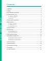
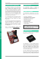
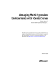
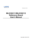
4D
SYSTEMS
TURNING TECHNOLOGY INTO ART
DATASHEET
1.44” microLCD GOLDELOX Display
µLCD-144-G2
Document Date: 5th September 2012
Document Revision: 1.0
Uncontrolled Copy when printed or downloaded.
Please refer to the 4D Systems website for the latest Revision of this document
microLCD GOLDELOX DISPLAY
Overview
The μLCD-144-G2 display module is compact and cost effective and features a 1.44” LCD TFT screen,
which is the smallest LCD TFT module available from 4D Systems. Driven by the GOLDELOX processor,
the μLCD-144-G2 is the perfect compact display solution for any application requiring a small embedded
screen.
The module is an elegant combination of a 1.44” TFT LCD screen, along with a modest but
comprehensive collection of I/O Features. These include a micro-SD card connector, two general
purpose input/output pins (GPIO's) with Dallas 1-Wire Support, Analog Input and sound generation
capability, along with serial communications.
Embedded at the heart of the design is the GOLDELOX
processor, which is driven by a highly optimised virtual core
engine called EVE (Extensible Virtual Engine).
This display module serves as a perfect solution to be
deployed at the forefront of any product design, requiring a
brilliance of colour, animation or images on any application.
This GOLDELOX driven Intelligent Display Module is a perfect
example of where art meets technology.
The µLCD-144-G2 has a 1.44” TFT LCD Display that
showcases the power and capabilities of the GOLDELOX
processor. Combining a resolution of 128x128 pixels with
65K True to Life colours, this display module is perfect for
animations, slideshows and other multimedia presentations.
Basic audio generation is possible on the module through
the use of RTTTL sounds and beeps. These can be executed
easily with a simple command, and are non-blocking which
enables user code to be executed while audio is playing.
The micro-SD card slot on the module provides the user with
expandable memory space suitable for multimedia file
retrieval, including images, animations and movie clips, as
well as data logging applications.
This microLCD module can be programmed in its native 4DGL
language (similar to C), using the Workshop 4 IDE Software
tool suite. It can also be configured very easily as a serial
slave device, for use with your favourite host controller.
Freedom is at your fingertips with the intelligent μLCD-144G2 display module.
microLCD GOLDELOX DISPLAY
Contents
1. Description...................................................................................................................................4
2. Features .......................................................................................................................................4
3. Pin Configuration and Summary ..................................................................................................5
4. Hardware Interface - Pins.............................................................................................................6
4.1. Serial Ports - COM0 UART ...................................................................................................................... 6
4.2. General Purpose I/O............................................................................................................................... 6
4.3. System Pins ............................................................................................................................................ 7
5. PmmC/Firmware Programming ...................................................................................................8
6. Module Features ..........................................................................................................................8
6.1. Display – 1.44” LCD TFT .......................................................................................................................... 8
6.2. GOLDELOX Processor ............................................................................................................................. 8
6.3. SD/SDHC Memory Cards ........................................................................................................................ 9
7. Display Precautions......................................................................................................................9
8. Hardware Tools..........................................................................................................................10
8.1. 4D Programming Cable ........................................................................................................................ 10
8.2. Development Hardware ....................................................................................................................... 10
9. 4DGL - Software Language .........................................................................................................10
10. 4D Systems - Workshop 4 IDE ..................................................................................................11
10.1. Workshop 4 – Designer Environment ................................................................................................ 11
10.2. Workshop 4 – ViSi Environment......................................................................................................... 11
10.3. Workshop 4 – Serial Environment...................................................................................................... 12
11. Mechanical Details ...................................................................................................................13
12. Schematic Diagram ..................................................................................................................14
13. Specifications and Ratings........................................................................................................15
14. Legal Notice..............................................................................................................................17
15. Contact Information .................................................................................................................17
microLCD GOLDELOX DISPLAY
4D SYSTEMS
µLCD-144-G2
1. Description
2. Features
The μLCD-144-G2 is an nifty little display module in
the 4D Systems microLCD graphics display range.
Featuring a 1.44” 128x128 resolution display, it is
the ideal size for attractive embedded display
applications.
• Low-cost 1.44” LCD display graphics user
interface solution.
Driving the module and its peripherals is the
GOLDELOX processor, a very capable chip which
provides impressive graphics power, programmed
with 4D Systems Workshop 4 IDE. 4D Systems
Workshop enables graphic solutions to be
constructed rapidly and with ease due to its design
being solely for 4D’s graphics controllers.
The
μLCD-144-G2 has
a modest but
comprehensive range of features suited for an
application requiring a bright eye catching display,
an analog input, Dallas 1-wire sensor capability,
audio generation, or simply digital I/O. This is truly
an impressive little module.
• 128 x 128 resolution, RGB 65K true to life
colours, LCD TFT screen.
• LED back lighting with greater than 150° viewing
angle
• Easy 10 pin interface to any host device:
3.3Vout, IO2, GND, IO1, RESET, GND, RX, TX,
+5V, 5V OUT
• Powered by the 4D-Labs GOLDELOX processor
(also available as separate OEM IC)
• 10KB of flash memory for user code storage and
510 bytes of RAM for user variables (255 x 16bit
vars).
• Asynchronous hardware serial UART port with
auto-baud, TTL interface, with 300 to 600K
baud.
• 2 x General Purpose I/O pins.
IO1 supports:
• Digital I/O
• A/D Converter with 8/10 bit resolution
• Complex sound generation
• Dedicated RTTTL tune engine
• Multi-Switch Joystick, Buttons
• Dallas 1-Wire
IO2 supports:
• Digital I/O
• Complex sound generation
• Dedicated RTTTL tune engine
• Dallas 1-Wire
• On-board micro-SD memory card adaptor for
multimedia storage and data logging purposes.
HC memory card support is also available for
cards larger than 4GB.
• Built in extensive 4DGL graphics and system
library functions.
• Display full colour images, animations, icons and
video clips.
• Supports all available Windows fonts and
characters (imported as external fonts).
• 4.0V to 5.5V range operation (single supply),
nominal 5.0V.
• Module dimensions: 31.0 x 42.0 x 14mm
(including header pins).
• Weight ~ 10g.
• Display Viewing Area: 25.5 x 26.5mm
• RoHS Compliant.
© 2012 4D SYSTEMS
Page 4 of 17
www.4dsystems.com.au
microLCD GOLDELOX DISPLAY
4D SYSTEMS
µLCD-144-G2
3. Pin Configuration and Summary
(2)
(4)
5V OUT IO2
+5V
(1)
Pin
Symbol
I/O
1
+5V
P
2
5V OUT
P
3
TX
O
4
IO2
I/O
5
RX
I
6
7
8
IO1
GND
GND
I/O
P
P
9
RESET
I
10
3.3V
P
TX
(3)
(6)
(8) (10)
IO1 GND 3.3V
RX
(5)
GND
(7)
RES
(9)
Interface/Programming Header
Description
Main Voltage Supply +ve input pin. Reverse polarity protected. Range is 4.0V to
5.5V, nominal 5.0V.
5V OUT provides approximately 4.7 V through a protection diode.
Asynchronous Serial Transmit pin. Output data is at TTL voltage levels. Connect
this pin to external device Serial Receive (Rx) signal. This pin is tolerant up to 5.0V
levels.
General purpose IO2 pin. See section 2.2 for more detail.
Asynchronous Serial Receive pin. Connect this pin to external device Serial
Transmit (Tx) signal. This pin is tolerant up to 5.0V levels.
General purpose IO1 pin. See section 2.2 for more detail.
Supply Ground.
Supply Ground.
Master Reset signal. Internally pulled up to 3.3V via a 4.7K resistor. An active Low
pulse greater than 2.0μs will reset the module. If the module needs to be reset
externally, only use open collector type circuits. This pin is not driven low by any
internal conditions. The host should control this pin via one of its port pins using
an open collector/drain arrangement.
Regulated 3.3 Volts output, maximum available current 50mA to power external
circuitry.
I = Input, O = Output, P = Power
© 2012 4D SYSTEMS
Page 5 of 17
www.4dsystems.com.au
microLCD GOLDELOX DISPLAY
4D SYSTEMS
µLCD-144-G2
4. Hardware Interface - Pins
The μLCD-144-G2 provides both a hardware and
software interface. This section describes in detail
the hardware interface pins of the device.
4.1. Serial Ports - COM0 UART
The μLCD-144-G2 has a dedicated hardware UART
that can communicate with external serial devices.
The primary features are:
• Full-Duplex 8 bit data transmission and reception
through the TX and RX pins.
• Data format: 8 bits, No Parity, 1 Stop bit.
• Auto Baud feature.
• Baud rates from 300 baud up to 600K baud.
GPIO Functions and Features
Function
IO1 IO2
Digital Input
Digital Output
A/D Converter 8/10 bits
Joystick – 5 position multi-switch
Dallas 1-Wire support
Sound Generation, RTTTL Tunes
√
√
√
√
√
√
√
√
--√
√
Input/Output:
Both IO1 and IO2 pins can be programmed to be
Inputs or Outputs. Diagram below shows a LED
connected to IO1 (programmed as an output) and
a button connected to IO2 (programmed as an
input).
The Serial port is also the primary interface for
downloading compiled 4DGL application code as
well as future PmmC/Firmware updates for the onboard GOLDELOX processor. Refer to Section 5.
PmmC/Firmware Programming for more details.
TX pin 3 (Serial Transmit):
Asynchronous Serial port Transmit pin, TX. The
serial output data is at TTL voltage levels. Connect
this pin to external serial device Rx signal.
RX pin 5 (Serial Receive):
Asynchronous Serial port Receive pin, RX. Connect
this pin to external serial device Transmit Tx signal.
Analogue to Digital Converter:
The IO1 pin can be programmed as an A/D input.
Option is available to select 8 bit or 10 bit
resolution. Diagram below is a circuit of a Light
Dependant Resistor (LDR) connected to IO1 to
measure and record changes in ambient light.
4.2. General Purpose I/O
There are 2 GPIO pins available, IO1 and IO2. Each
GPIO has a multitude of high level functions
associated with it and these can be selected within
4DGL user application code.
Refer to the separate document titled
“GOLDELOX-4DGL-Internal-Functions.pdf” for a
complete set of built in 4DGL library functions.
IO1 pin 6 (General Purpose IO1):
General purpose IO1 pin. The following table lists
the available GPIO functions and features.
IO2 pin 4 (General Purpose IO2):
General purpose IO2 pin. The following table lists
the available GPIO functions and features.
Note: GPIO pins are 5.0V tolerant.
© 2012 4D SYSTEMS
Joystick - Multi Switch:
Multiple buttons or a multi-switch Joystick can be
connected to the IO1 pin on the μLCD-144-G2
module. Up to five buttons or a 5 position multiswitch joystick connects to a junction of a resistor
ladder network that forms a voltage divider. The
A/D converter of the IO1 pin internally reads the
analogue value and decodes it accordingly. This
feature is supported by dedicated 4DGL library
functions. The following diagrams indicate how to
connect up to five individual buttons or a multi
switch joystick to the IO1 pin.
Page 6 of 17
www.4dsystems.com.au
microLCD GOLDELOX DISPLAY
4D SYSTEMS
µLCD-144-G2
Sound Output:
The μLCD-144-G2 module is capable of generating
complex sounds and RTTTL tunes from its IO1 and
IO2 pins. A simple speaker circuit as shown below
can be utilised.
4.3. System Pins
Unused buttons do not need resistors to be
connected to the circuit. Table below lists the
buttons and corresponding resistor values.
Number of
Buttons
1
2
3
4
5
Button
Number
SW1
SW2
SW3
SW4
SW5
Resistor
Value
22K
10K
4.7K
2.2K
1.2K
5V Out (~4.7V)
Pin 2:
External circuitry that requires approximately 5V
supply can be powered up via this pin. Maximum
available current is 50mA.
GND (Module Ground)
Pins 7, 8:
Device ground pins. These pins must be connected
to ground.
Dallas 1-Wire:
The Dallas 1-Wire protocol is a form of serial
communications designed to operate over a single
data line plus ground reference. Multiple 1 Wire
devices can be attached to the same shared data
line to network many devices. One wire device
support is available on both the IO1 and the IO2
pins on the μLCD-144-G2 module.
The following diagram depicts a typical 1-Wire
temperature sensor interface.
© 2012 4D SYSTEMS
+5V (Module Voltage Input)
Pin 1:
Module supply voltage input pin. This pin must be
connected to a regulated supply voltage in the
range of 4.0 Volts to 5.5 Volts DC. Nominal
operating voltage is 5.0 Volts.
RESET (Module Master Reset)
Pin 9:
Module Master Reset pin. An active low pulse of
greater than 2 micro-seconds will reset the
module. Internally pulled up to 3.3V via a 4.7K
resistor. Only use open collector type circuits to
reset the device if an external reset is required.
3.3Vout (3.3V Regulated Output)
Pin 10:
External circuitry that requires a regulated 3.3V
supply can be powered up via this pin. Maximum
available current is 50mA.
Page 7 of 17
www.4dsystems.com.au
microLCD GOLDELOX DISPLAY
4D SYSTEMS
µLCD-144-G2
5. PmmC/Firmware Programming
6. Module Features
The GOLDELOX processor on the μLCD-144-G2
module can be re-programmed with the latest
PmmC configuration for updates and future
proofing. The chip-level configuration is available
as a PmmC (Personality-module-micro-Code) file
and the programming must be performed over the
serial interface. The chip-resident internal 4DGL
functions are part of the GOLDELOX PmmC
configuration file so please check regularly for the
latest updates and enhancements.
The μLCD-144-G2 module is designed to
accommodate most applications. Some of the
main features of the module are listed below.
It is recommended that the μLCD-144-G2 display
module be socketed on the application board so
that it can be easily removed for PmmC
programming.
•
•
•
•
•
•
•
•
•
The PmmC file is programmed into the device with
the aid of Workshop 4, the 4D Systems IDE
software (See Section 10). To provide a link
between the PC and the ICSP interface, a specific
4D Programming Cable is required and is available
from 4D Systems.
Using a non-4D programming interface could
damage your display, and void your Warranty.
6.1. Display – 1.44” LCD TFT
The μLCD-144-G2 is equipped with a full colour
LCD TFT screen. Some of the features of the screen
are:
Screen Size: 1.44”diagonal
128 x 128 Resolution LCD TFT Display
Screen Dimensions: 30.9 x 36.5mm
Viewing Area: 25.5 x 26.5mm
65K true to life colours
Luminance: 250 cd/m2
Contrast Ratio: 450
Viewing Angle: > 150 degrees
LED Back lighting
Note: The Displays used are the highest rated
‘Grade A’ Displays, which allow for 0-4 defective
pixels. A defective pixel could be solid Black
(Dead), White, Red, Green or Blue.
6.2. GOLDELOX Processor
The module is designed around the GOLDELOX
Graphics Processor from 4D-Labs.
The GOLDELOX is a custom embedded graphics
processor designed to interface with many popular
OLED and LCD display panels. Powerful graphics,
text, image, animation and countless more
features are built right inside the chip. It offers a
simple plug-n-play interface to many 8bit 80-Series
colour LCD and OLED displays.
The chip is designed to work with minimal design
effort and all of the data and control signals are
provided by the chip to interface directly to the
display. Simply choose your display and interface it
© 2012 4D SYSTEMS
Page 8 of 17
www.4dsystems.com.au
microLCD GOLDELOX DISPLAY
4D SYSTEMS
µLCD-144-G2
to the GOLDELOX on your application board. This
offers enormous advantage to the designer in
development time and cost saving and takes away
all of the burden of low level design.
The data sheet for the chip is available from the
http://www.4dsystems.com.au website:
“GOLDELOX-DS-revx.pdf”
6.3. SD/SDHC Memory Cards
The module supports micro-SD memory cards via
the on-board micro-SD
connector. The memory
card is used for all
multimedia file retrieval
such
as
images,
animations and movie
clips. The memory card
can also be used as general purpose storage for
data logging applications. Support is available for
off the shelf micro-SD and high capacity HC
memory cards (4GB and above).
7. Display Precautions
• Avoid having to display the same image/object
on the screen for lengthy periods of time. This will
cause a burn-in which is a common problem with
all types of display technologies. Blank the screen
after a while or dim it very low by adjusting the
contrast. Better still; implement a screen saver
feature.
• Moisture and water can damage the display.
Moisture on the surface of a powered display will
cause the electrodes to corrode. Wipe off any
moisture gently or let the display dry before usage.
• Dirt from fingerprint oil and fat can easily stain
the surface of the display. Gently wipe off any
stains with a soft lint-free cloth.
• The performance of the display will degrade
under high temperature and humidity. Avoid such
conditions when storing.
• Do not tamper with the display flex cable that is
connected to the control board. This may affect
the connection between the display and the
driving circuitry and cause failure.
• Displays are susceptible to mechanical shock and
any force exerted on the module may result in
deformed zebra stripes, a cracked display cell and
broken backlight
• Always use the mounting holes on the module's
printed circuit board to mount the display.
© 2012 4D SYSTEMS
Page 9 of 17
www.4dsystems.com.au
microLCD GOLDELOX DISPLAY
4D SYSTEMS
µLCD-144-G2
8. Hardware Tools
9. 4DGL - Software Language
The following hardware tools are required for full
control of the μLCD-144-G2 module.
The heart of the μLCD-144-G2 module is the
GOLDELOX graphics processor from 4D Labs. The
GOLDELOX belongs to a family of processors
powered by a highly optimised soft core virtual
engine, EVE (Extensible Virtual Engine).
8.1. 4D Programming Cable
The 4D Programming Cable is an essential
hardware tool to program, customise and test the
μLCD-144-G2 module.
The 4D Programming Cable is used to program a
new Firmware/PmmC and downloading compiled
4DGL code into the module. It even serves as an
interface for communicating serial data to the PC.
The 4D Programming Cable is available from 4D
Systems, www.4dsystems.com.au
EVE is a proprietary, high performance virtualmachine with an extensive byte-code instruction
set optimised to execute compiled 4DGL
programs. 4DGL (4D Graphics Language) was
specifically developed from ground up for the EVE
engine core. It is a high level language which is
easy to learn and simple to understand yet
powerful enough to tackle many embedded
graphics applications.
4DGL is a graphics oriented language allowing
rapid application development, and the syntax
structure was designed using elements of popular
languages such as C, Basic, Pascal and others.
Programmers familiar with these languages will
feel right at home with 4DGL. It includes many
familiar instructions such as IF..ELSE..ENDIF,
WHILE..WEND, REPEAT..UNTIL, GOSUB..ENDSUB,
GOTO, PRINT as well as some specialised
instructions
SERIN,
SEROUT,
GFX_LINE,
GFX_CIRCLE and many more.
8.2. Development Hardware
4D Systems has designed a development board
compatible with the μOLED-96-G2, enabling easy
prototyping to take place and to experiment with
the μOLED-96-G2 display module.
For detailed information pertaining to the 4DGL
language, please refer to the following documents:
“4DGL-Programmers-Reference-Manual.pdf”
“GOLDELOX-4DGL-Internal-Functions.pdf”
To assist with the development of 4DGL
applications, the Workshop 4 IDE combines a fullfeatured editor, a compiler, a linker and a downloader into a single PC-based application. It's all
you need to code, test and run your applications.
4DGL is available to be written in two of the three
environments offered by the Workshop 4 IDE,
Designer and ViSi.
This development board is called the 4DevBoard,
and is available from the 4D Systems website
store, or from 4D Systems distributors.
© 2012 4D SYSTEMS
Page 10 of 17
www.4dsystems.com.au
microLCD GOLDELOX DISPLAY
4D SYSTEMS
µLCD-144-G2
10. 4D Systems - Workshop 4 IDE
10.1. Workshop 4 – Designer Environment
Workshop 4 is a comprehensive software IDE that
provides an integrated software development
platform for all of the 4D family of processors and
modules. The IDE combines the Editor, Compiler,
Linker and Downloader to develop complete 4DGL
application code. All user application code is
developed within the Workshop 4 IDE.
Choose the Designer environment to write 4DGL
code in its raw form.
The Designer environment provides the user with
a simple yet effective programming environment
where pure 4DGL code can be written, compiled
and downloaded to the μLCD-144-G2.
The Workshop 4 IDE supports multiple
development environments for the user, to cater
for different user requirements and skill level.
•
•
•
The Designer environment enables the user to
write 4DGL code in its natural form to
program the μLCD-144-G2.
A visual programming experience, suitably
called ViSi, enables drag-and-drop type
placement of objects to assist with 4DGL code
generation and allows the user to visualise
how the display will look while being
developed.
A Serial environment is also provided to
transform the μLCD-144-G2 into a slave serial
module, allowing the user to control the
display from any host microcontroller or
device with a serial port.
The Workshop 4 IDE is available from the 4D
Systems website. www.4dsystems.com.au
For a comprehensive manual on the Workshop 4
IDE Software, refer to its documentation from the
4D Systems website.
“Workshop-4-IDE-User-Manual.pdf”
© 2012 4D SYSTEMS
10.2. Workshop 4 – ViSi Environment
ViSi was designed to make the creation of
graphical displays a more visual experience.
ViSi is a great software tool that allows the user to
see the instant results of their desired graphical
layout. Additionally, there is a selection of inbuilt
dials, gauges and meters that can simply be placed
onto the simulated module display. From here
each object can have its properties edited, and at
the click of a button all relevant 4DGL code
associated with that object is produced in the user
program. The user can then write 4DGL code
around these objects to utilise them in the way
they choose.
Page 11 of 17
www.4dsystems.com.au
microLCD GOLDELOX DISPLAY
4D SYSTEMS
µLCD-144-G2
10.3. Workshop 4 – Serial Environment
The Serial environment in the Workshop 4 IDE
provides the user the ability to transform the
μLCD-144-G2 into a slave serial graphics controller.
This enables the user to use their favourite
microcontroller or serial device as the Host,
without having to learn 4DGL or program in a
separate IDE. Once the module is configured and
downloaded to from the Serial Environment,
simple graphic commands can be sent from the
users host microcontroller to display primitives,
images, sound or even video.
Refer to the Serial Environment section in the
Workshop 4 user manual, for a complete listing of
all the supported serial commands
“Workshop-4-IDE-User-Manual.pdf”
By default, each module shipped from the 4D
Systems factory will come pre-programmed ready
for use in the Serial mode.
© 2012 4D SYSTEMS
Page 12 of 17
www.4dsystems.com.au
4D SYSTEMS
µLCD-144-G2
microLCD GOLDELOX DISPLAY
11. Mechanical Details
© 2012 4D SYSTEMS
Page 13 of 17
www.4dsystems.com.au
4D SYSTEMS
µLCD-144-G2
microLCD GOLDELOX DISPLAY
12. Schematic Diagram
© 2012 4D SYSTEMS
Page 14 of 17
www.4dsystems.com.au
microLCD GOLDELOX DISPLAY
4D SYSTEMS
µLCD-144-G2
13. Specifications and Ratings
ABSOLUTE MAXIMUM RATINGS
Operating ambient temperature ................................................................................................... -15°C to +65°C
Storage temperature .......................................................................................................................... -30°C +80°C
Voltage on any digital input pin with respect to GND ....................................................................... -0.3V to 6.0V
Voltage on SWITCH pin with respect to GND ................................................................................... -0.3V to 6.0V
Voltage on VCC with respect to GND ................................................................................................. -0.3V to 6.0V
Maximum current out of GND pin .............................................................................................................. 300mA
Maximum current into VCC pin .................................................................................................................. 250mA
Maximum output current sunk/sourced by any pin ....................................................................................... 4mA
Total power dissipation .................................................................................................................................. 1.0W
NOTE: Stresses above those listed here may cause permanent damage to the device. This is a stress rating only
and functional operation of the device at those or any other conditions above those indicated in the
recommended operation listings of this specification is not implied. Exposure to maximum rating conditions
for extended periods may affect device reliability.
RECOMMENDED OPERATING CONDITIONS
Parameter
Supply Voltage (VCC)
Operating Temperature
Input Low Voltage (VIL)
Input High Voltage (VIH)
Reset Pulse
Operational Delay
Conditions
RX Pin
RX Pin
External Open Collector
Power-Up or External Reset
Min
4.0
-10
GND
2.0
2.0
1000
Typ
5.0
--3.3
---
Max
5.5
+60
0.8
5.0
---
Units
V
°C
V
V
µs
ms
GLOBAL CHARACTERISTICS BASED ON OPERATING CONDITIONS
Parameter
Supply Current (ICC)
Low Power Current (ICC)
Output Low Voltage
(VOL)
Output High Voltage
(VOH)
A/D Converter
Resolution
Capacitive Loading
Flash Memory
Endurance
© 2012 4D SYSTEMS
Conditions
VCC = 5.0V
VCC = 5.0V, Contrast = 0
Min
14
300
Typ
40
500
Max
120
--
Units
mA
µA
TX, IO1, IO2, IOL = 3.4mA
--
--
0.4
V
TX, IO1, IO2, IOL = -2.0mA
2.4
--
3.3
V
IO1 Pin
--
8
10
bits
All pins
--
--
50
pF
PmmC/4DGL Programming
--
1000
--
E/W
Page 15 of 17
www.4dsystems.com.au
microLCD GOLDELOX DISPLAY
4D SYSTEMS
µLCD-144-G2
OPTICAL CHARACTERISTICS
Parameter
Contrast ratio (Centre point)
Condition
Luminance of white (Centre point)
White Uniformity
Response
Rising + Falling
Time
(Tr + Tf)
Vertical above Centre
Vertical below Centre
Viewing Angle
Horizontal Left of Centre
Horizontal Right of Centre
Back-light On
Contrast Ratio > 10
Min
300
Typ
450
Max
--
Units
--
160
200
230
Cd/m
80
--
--
%
--
--
240
ms
30
30
30
30
2
Degrees
ORDERING INFORMATION
Order Code: μLCD-144-G2
Package: 65mm x 50mm x 30mm
Packaging: Module sealed in antistatic foam padded 4D Systems Box
© 2012 4D SYSTEMS
Page 16 of 17
www.4dsystems.com.au
microLCD GOLDELOX DISPLAY
4D SYSTEMS
µLCD-144-G2
14. Legal Notice
Proprietary Information
The information contained in this document is the property of 4D Systems Pty. Ltd. and may be the subject of
patents pending or granted, and must not be copied or disclosed without prior written permission.
4D Systems endeavours to ensure that the information in this document is correct and fairly stated but does
not accept liability for any error or omission. The development of 4D Systems products and services is
continuous and published information may not be up to date. It is important to check the current position with
4D Systems. 4D Systems reserves the right to modify, update or makes changes to Specifications or written
material without prior notice at any time.
All trademarks belong to their respective owners and are recognised and acknowledged.
Disclaimer of Warranties & Limitation of Liability
4D Systems makes no warranty, either expressed or implied with respect to any product, and specifically
disclaims all other warranties, including, without limitation, warranties for merchantability, non-infringement
and fitness for any particular purpose.
Information contained in this publication regarding device applications and the like is provided only for your
convenience and may be superseded by updates. It is your responsibility to ensure that your application meets
with your specifications.
Images and graphics used throughout this document are for illustrative purposes only. All images and graphics
used are possible to be displayed on the 4D Systems range of products, however the quality may vary.
In no event shall 4D Systems be liable to the buyer or to any third party for any indirect, incidental, special,
consequential, punitive or exemplary damages (including without limitation lost profits, lost savings, or loss of
business opportunity) arising out of or relating to any product or service provided or to be provided by 4D
Systems, or the use or inability to use the same, even if 4D Systems has been advised of the possibility of such
damages.
4D Systems products are not fault tolerant nor designed, manufactured or intended for use or resale as on line
control equipment in hazardous environments requiring fail – safe performance, such as in the operation of
nuclear facilities, aircraft navigation or communication systems, air traffic control, direct life support machines
or weapons systems in which the failure of the product could lead directly to death, personal injury or severe
physical or environmental damage (‘High Risk Activities’). 4D Systems and its suppliers specifically disclaim
any expressed or implied warranty of fitness for High Risk Activities.
Use of 4D Systems’ products and devices in 'High Risk Activities' and in any other application is entirely at the
buyer’s risk, and the buyer agrees to defend, indemnify and hold harmless 4D Systems from any and all
damages, claims, suits, or expenses resulting from such use. No licenses are conveyed, implicitly or otherwise,
under any 4D Systems intellectual property rights.
15. Contact Information
For Technical Support: [email protected]
For Sales Support: [email protected]
Website: www.4dsystems.com.au
Copyright 4D Systems Pty. Ltd. 2000-2012.
© 2012 4D SYSTEMS
Page 17 of 17
www.4dsystems.com.au
Mouser Electronics
Authorized Distributor
Click to View Pricing, Inventory, Delivery & Lifecycle Information:
4D Systems:
uLCD-144-G2