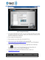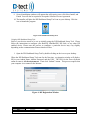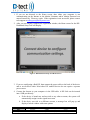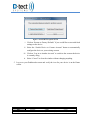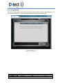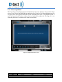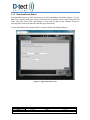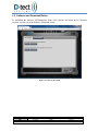
1
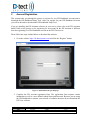
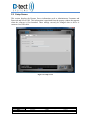
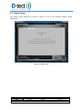
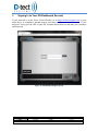
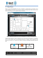
SETUP AND OPERATING INSTRUCTIONS FOR THE SOFTWARE Including DX-Dashboard Setup Tool DX-Assistant D-tect Systems Group Visionary Products Inc. 11814 South Election Road, Suite 200 Draper, UT 84020 www.dtectsystems.com Table of Contents 1 2 3 4 5 DX-Dashboard Software and DX-Dashboard Setup Tool Introduction .................................. 3 1.1 Key Features ................................................................................................................... 3 1.2 DX-Assistant Network Server ........................................................................................ 3 1.3 DX-View Software ......................................................................................................... 4 1.4 Quick Start and Getting Started Guides .......................................................................... 4 Account Registration ............................................................................................................... 5 2.1 Using the DX-Dashboard Setup Tool ............................................................................. 7 2.2 Device Settings Section ................................................................................................ 10 2.2.1 Communications Section .......................................................................................... 10 2.2.2 Firmware Update Section ......................................................................................... 13 2.2.3 Proxy Settings Section .............................................................................................. 14 2.3 Setup Screen ................................................................................................................. 15 2.4 About Screen................................................................................................................. 16 Signing In to Your DX-Dashboard Account ......................................................................... 17 3.1 Home Screen ................................................................................................................. 18 3.1.1 Home Screen Buttons ............................................................................................... 20 3.1.2 Settings Button ......................................................................................................... 21 3.1.2.1 Upload Map or Blueprint .......................................................................................... 21 3.1.2.2 Reset Admin Password ............................................................................................. 22 3.1.2.3 Setup User Account .................................................................................................. 22 3.1.3 Help Section ............................................................................................................. 23 3.1.4 Event Log Button ..................................................................................................... 24 3.1.5 Download Event Button ........................................................................................... 25 3.2 Software and Download Button .................................................................................... 26 3.3 Radiation Level Graph Button ...................................................................................... 27 3.4 Device Configuration Button ........................................................................................ 28 3.4.1 Device Screen ........................................................................................................... 29 3.4.2 Properties Screen ...................................................................................................... 30 3.4.3 Alarm Screen ............................................................................................................ 31 3.4.4 Ethernet Screen (Rad-DX only) ............................................................................... 32 3.4.5 Wi-Fi Screen (Rad-DX only) ................................................................................... 33 3.4.6 SensorNet Mesh Screen ............................................................................................ 34 3.4.7 Firmware Update Screen .......................................................................................... 35 3.4.8 Proxy Screen ............................................................................................................. 36 Software Usage Statement ..................................................................................................... 37 Technical Support .................................................................................................................. 37 Document Number: V025295_01_DX-Dashboard_Manual.docx Date: 7/11/2014 Page: 2 of 37 D-tect Systems 11814 South Election Rd. Suite 200, Draper, UT 84020 (801) 495-2310 FAX (801) 495-2255 1 DX-Dashboard Software and DX-Dashboard Setup Tool Introduction This manual addresses the setup, configuration, and monitoring of a DX radiation detection system on the D-tect Systems Cloud server and a DX-Assistant server. The DX-Dashboard is not a software application installed on a PC like the DX-View. Instead, it is an Internet website hosted by D-tect Systems. The DX-Assistant is an appliance (computer) preloaded with the software needed to set up a local DX-Dashboard server hosted by you. DX-Dashboard runs on either the D-tect Cloud server or the DX Assistant (if installed at your facility). The DX-Dashboard Setup Tool is the PC software required to configure the DX family of products to communicate on your DX-Dashboard account. The DX-Dashboard Setup Tool works for both the D-tect Systems Cloud server and a DX-Assistant server. 1.1 Key Features Software Highlights Fast setup Hosted solution Monitor and control detectors remotely Real-time monitoring 128-bit AES encryption 1.2 DX-Assistant Network Server The DX Assistant is a stand-alone local server specifically designed to support a network of DX enabled radiation detectors inside your own protected firewall. This appliance comes installed with the DX-Dashboard Setup Tool and DX-Dashboard software and allows for flexibility in configuring detectors to communicate via Ethernet and Wi-Fi (if available) and SensorNet Mesh networking options. The DX Assistant includes: • • • One server box (Dell Tower) with a power cable Microsoft Server 2011 Essentials operating system DX-Dashboard software Document Number: V025295_01_DX-Dashboard_Manual.docx Date: 7/11/2014 Page: 3 of 37 D-tect Systems 11814 South Election Rd. Suite 200, Draper, UT 84020 (801) 495-2310 FAX (801) 495-2255 When setting up a DX network with the DX Assistant server, please refer to the DX Assistant Installation Guide for complete installation instructions. 1.3 DX-View Software TBD Whereas the DX-Dashboard is a server based system, the DX-View is a software application that can be used to monitor a network of DX enabled devices from one PC. Multiple detectors can be monitored in real-time; however they cannot be monitored from an Internet connected device. 1.4 Quick Start and Getting Started Guides Additional documentation, such as Getting Started and Quick Start Guides, is available to help you set up your DX enabled network of detectors including: DX-Dashboard Setup Tool Quick Start Guide DX-Assistant Quick Start Guide Document Number: V025295_01_DX-Dashboard_Manual.docx Date: 7/11/2014 Page: 4 of 37 D-tect Systems 11814 South Election Rd. Suite 200, Draper, UT 84020 (801) 495-2310 FAX (801) 495-2255 2 Account Registration This section takes you through the process to register for you DX-Dashboard Account and to download the DX-Dashboard Setup Tool. After you register for your DX-Dashboard Account you will be directed to download the DX-Dashboard Setup Tool. If you are installing the DX-Assistant software on your server, please refer to the DX-Assistant Install Guide as the process to for registering for an account on the DX-Assistant is different from the registering for a DX-Dashboard account on the DX Cloud server. Please follow the steps outlined below to download this software. 1. Go to the website: https://dx.dtectsystems.com and click the “Register” button. Figure 1: DX-Dashboard Login Webpage 2. Complete the DX Account registration form. The registration form requests contact information as well as a user defined Admin Name and Password. Because you are using the DX-Dashboard to monitor your network of radiation detectors do not download the DX-View software. Document Number: V025295_01_DX-Dashboard_Manual.docx Date: 7/11/2014 Page: 5 of 37 D-tect Systems 11814 South Election Rd. Suite 200, Draper, UT 84020 (801) 495-2310 FAX (801) 495-2255 Figure 2: DX Registration Webpage 3. An Account Confirmation email will be sent to the specified email address and contains an assigned Customer ID. The email also confirms your Admin Name and Password. Do not lose your Admin Name or Password. 4. Please complete all information fields. 5. Please remember to not click the link to download DX-View. 6. After you receive your email confirmation, please go to the URL https://dx.dtectsystems.com/web/loginScreen.html and sign in to your DX-Dashboard account with your Username and Password. 7. Click on the Download Software Icon on the upper right hand section of the Home screen. Then click on the Download button below the Setup software for configuring D-tect devices for use with the DX Dashboard. 8. If you require a CD to install the DX-Dashboard software, contact us at [email protected]. Document Number: V025295_01_DX-Dashboard_Manual.docx Date: 7/11/2014 Page: 6 of 37 D-tect Systems 11814 South Election Rd. Suite 200, Draper, UT 84020 (801) 495-2310 FAX (801) 495-2255 9. Several installation windows will appear that will require you to click Next, Install, and Finish. You will also be required to accept the Software License Agreement. 10. The installer will place the DX-Dashboard Setup Tool icon on your desktop. Click the icon to launch the program. Figure 3: DX-Dashboard Desktop Icon Using the DX-Dashboard Setup Tool Each of your devices needs to be set up initially using the DX-Dashboard Setup Tool. Please follow the instructions to configure your Rad-DX, MiniRad-DX, DX-Link, or any other DX enabled device. Please note the process to configure a particular device may vary slightly depending on the communication features that device has. 1. Open the DX-Dashboard Setup Tool by double-clicking on the icon on your desktop. When the DX-Dashboard Setup Tool runs for the first time, a registration window will display. Fill in your Admin Name, Admin Password, and the URL. The URL for the D-tect Systems online account is: d1.dtectsystems.net. Then click “Submit” button. This process requires that your computer is to connect to the Internet. Figure 4: DX Registration Window Document Number: V025295_01_DX-Dashboard_Manual.docx Date: 7/11/2014 Page: 7 of 37 D-tect Systems 11814 South Election Rd. Suite 200, Draper, UT 84020 (801) 495-2310 FAX (801) 495-2255 1. If you are not directed to the Home screen, then either your computer is not communicating on the Internet or the Admin Username and/or Admin Password was entered incorrectly. Please try again. If the registration is not successful, please contact tech support at [email protected]. 2. After you successfully complete the registration window, the Home screen for the DXDashboard Setup Tool will display. Figure 5: DX-Dashboard Setup Tool Home Screen 3. If you are configuring a Rad-DX, then connect the power cable to the back of the device and to an electrical outlet. Most other DX enabled devices do not require a separate power source. 4. Connect the detector to your computer via the USB cable. A DX-Link can be inserted into a USB port directly. a. If the device is brand new and not tied to any other accounts, the system will automatically assign it to the signed in account. b. If the device was tied to a different account, a message box will pop up and display a locked window with some options. Document Number: V025295_01_DX-Dashboard_Manual.docx Date: 7/11/2014 Page: 8 of 37 D-tect Systems 11814 South Election Rd. Suite 200, Draper, UT 84020 (801) 495-2310 FAX (801) 495-2255 Figure 6: Locked Device Options Screen i. Click on “Restore to Factory Defaults” if you would like to start with fresh settings on the device. ii. Select the “Switch Device to Current Account” button to automatically configure the device to your existing account. iii. Click on “Log in to Another Account” to switch to the account the device is currently using. iv. Select “Cancel” to close the window without changing anything. 5. Log on to your Dashboard account and verify the icon for your device is on the Home screen. Document Number: V025295_01_DX-Dashboard_Manual.docx Date: 7/11/2014 Page: 9 of 37 D-tect Systems 11814 South Election Rd. Suite 200, Draper, UT 84020 (801) 495-2310 FAX (801) 495-2255 Figure 7: DX-Dashboard Home Screen with Gray Icon 2.1 Device Settings Section 2.1.1 Communications Section The Communications screen in Device Settings is the default screen that appears once a device is connected via USB. This screen allows for configuration of the communication protocols for each device. Please be aware that not all DX enabled devices can communicate via Ethernet and Wi-Fi. Devices that only communicate via the SensorNet mesh network must communicate through a device that communicates Ethernet or Wi-Fi to work with the Dashboard account. The channel (frequency) that the SensorNet Mesh network operates on can also be changed here. If the channel is changed on one device, then all other devices will need to be changed to the same channel to be able to communicate with each other through the Mesh network. Document Number: V025295_01_DX-Dashboard_Manual.docx Date: 7/11/2014 Page: 10 of 37 D-tect Systems 11814 South Election Rd. Suite 200, Draper, UT 84020 (801) 495-2310 FAX (801) 495-2255 Figure 8: Device Settings: Communication Tab Document Number: V025295_01_DX-Dashboard_Manual.docx Date: 7/11/2014 Page: 11 of 37 D-tect Systems 11814 South Election Rd. Suite 200, Draper, UT 84020 (801) 495-2310 FAX (801) 495-2255 Verification of Configuration Go back to your DX-Dashboard account and verify that your device is communicating via Ethernet or Wi-Fi as configured. The icon on the Home screen will turn from gray to blue. Figure 9: DX-Dashboard Home Screen with Blue Icon Document Number: V025295_01_DX-Dashboard_Manual.docx Date: 7/11/2014 Page: 12 of 37 D-tect Systems 11814 South Election Rd. Suite 200, Draper, UT 84020 (801) 495-2310 FAX (801) 495-2255 2.1.2 Firmware Update Section As new firmware versions become available, you will be notified and given instructions to upload a new or updated firmware version to your device. Save the included firmware version in a convenient location. Select the device to be updated, locate the firmware file using the Browse feature, and press submit to update. This update may take several minutes. Figure 10: Device Settings: Firmware Update Screen Document Number: V025295_01_DX-Dashboard_Manual.docx Date: 7/11/2014 Page: 13 of 37 D-tect Systems 11814 South Election Rd. Suite 200, Draper, UT 84020 (801) 495-2310 FAX (801) 495-2255 2.1.3 Proxy Settings Section If your device needs to connect to the DX-Dashboard server through a proxy server, turn on the “Proxy Enabled” option. This will bring up two fields, “Proxy URL” and “Proxy Port.” Enter the IP address or URL of the proxy server the device is connecting to under “Proxy URL.” Enter the port number of the proxy server under “Proxy Port.” If the proxy requires authentication, turn on the “Authentication Enabled” option. This brings up the fields “Proxy Username” and “Proxy Password.” Enter the proxy server username and password information into these fields, respectively. Figure 11: Device Settings: Proxy Settings Window Document Number: V025295_01_DX-Dashboard_Manual.docx Date: 7/11/2014 Page: 14 of 37 D-tect Systems 11814 South Election Rd. Suite 200, Draper, UT 84020 (801) 495-2310 FAX (801) 495-2255 2.2 Setup Screen This section displays the Remote Server information such as Administrator Username and Password and Server URL. This information is populated from the pop-up window that appears when the software is first launched. These settings can only be changed when a device is connected via USB cable. Figure 12: Setup Screen Document Number: V025295_01_DX-Dashboard_Manual.docx Date: 7/11/2014 Page: 15 of 37 D-tect Systems 11814 South Election Rd. Suite 200, Draper, UT 84020 (801) 495-2310 FAX (801) 495-2255 2.3 About Screen The About screen displays the software version as well as the technical support contact information. Figure 13: About Screen Document Number: V025295_01_DX-Dashboard_Manual.docx Date: 7/11/2014 Page: 16 of 37 D-tect Systems 11814 South Election Rd. Suite 200, Draper, UT 84020 (801) 495-2310 FAX (801) 495-2255 3 Signing In to Your DX-Dashboard Account If your network is on the D-tect Cloud Network, go to https://dx.dtectsystems.com on your smart device or computer’s internet browser and enter your Username and Password. If your network is local, go to the URL of your DX Assistant Network Server and enter your Username and Password. Figure 14: DX-Dashboard Sign-in Screen Document Number: V025295_01_DX-Dashboard_Manual.docx Date: 7/11/2014 Page: 17 of 37 D-tect Systems 11814 South Election Rd. Suite 200, Draper, UT 84020 (801) 495-2310 FAX (801) 495-2255 3.1 Home Screen When you open the DX-Dashboard on a PC, smartphone, or tablet and log in, the Home screen will be displayed. The Home screen will show a map or a blueprint and where the devices are located. (See Section 3.1.2.1 to upload a map or blueprint) Figure 15: DX-Dashboard Home Screen with one alarming device icon and five normal device icons During normal operation, each active Rad-DX device in the network will appear as a small blue icon. For the real-time dose rate measurement and device settings, click the button for the detector you want to see. A gray device window will pop up containing information about the unit. Normal (non-alarming) device Alarming device Non-operational or disconnected device Table 1: Device Icon Colors Document Number: V025295_01_DX-Dashboard_Manual.docx Date: 7/11/2014 Page: 18 of 37 D-tect Systems 11814 South Election Rd. Suite 200, Draper, UT 84020 (801) 495-2310 FAX (801) 495-2255 To access a graph of the current detection values, click on the white Graph button at the bottom left of the screen. To change the settings on the device, click the white gear, Settings, button at the bottom right of the screen. To see a summary of all detectors, click the button found in the top right (see Figure 17). Figure 16: Device Window containing information about a specific device. The Radiation Level Graph button (see Section 3.3) and Device Settings button (Section 3.4) are labeled. Document Number: V025295_01_DX-Dashboard_Manual.docx Date: 7/11/2014 Page: 19 of 37 D-tect Systems 11814 South Election Rd. Suite 200, Draper, UT 84020 (801) 495-2310 FAX (801) 495-2255 Click Blue Arrow to reveal Device Panel Figure 17: The Device Panel reveals a list of all DX enabled radiation detectors with dose rate information. 3.1.1 Home Screen Buttons At the top of the Home screen there are six buttons, which are links to the Home, Settings, Help, Event Log, Event Download and Software Download screens. Simply click button and you will enter the respective screen. Home Settings Help Event Log Event Download Software Download Table 2: DX-Dashboard Windows Document Number: V025295_01_DX-Dashboard_Manual.docx Date: 7/11/2014 Page: 20 of 37 D-tect Systems 11814 South Election Rd. Suite 200, Draper, UT 84020 (801) 495-2310 FAX (801) 495-2255 3.1.2 Settings Button The Settings section is where you upload a floor plan, site map, or satellite image. You can also reset the Admin Password and create a read-only User Account for monitoring purposes. Figure 18: Settings Application Screen 3.1.2.1 Upload Map or Blueprint Any map or blueprint in jpeg, bmp, png, or tif format can be uploaded. To upload the map or blueprint of your location: 1. Select the Settings icon at the top of the Home screen. 2. Select the Upload Image button. 3. Browse to the desired image file and click Open and Submit. Document Number: V025295_01_DX-Dashboard_Manual.docx Date: 7/11/2014 Page: 21 of 37 D-tect Systems 11814 South Election Rd. Suite 200, Draper, UT 84020 (801) 495-2310 FAX (801) 495-2255 3.1.2.2 Reset Admin Password Below are instructions to change the Admin Password. 1. 2. 3. 4. 5. 6. Select the Settings icon on the top the Home screen. Select the Reset Admin Password tab. Enter the Current Admin Password. Enter the New Admin Password. Retype the New Admin Password. Press the button, “Reset Password.” 3.1.2.3 Setup User Account You may setup one, and only one, User account for monitoring purposes only. The User account cannot view or change any settings. Instructions for adding a User account: 1. Select the Settings icon on the top the Home screen. 2. Select the Setup User Account tab. 3. Enter a username. 4. Enter a password. 5. Retype the password. 6. Press the “Submit” button. Document Number: V025295_01_DX-Dashboard_Manual.docx Date: 7/11/2014 Page: 22 of 37 D-tect Systems 11814 South Election Rd. Suite 200, Draper, UT 84020 (801) 495-2310 FAX (801) 495-2255 3.1.3 Help Section The Help screen provides information explaining current software features and functions. You may download the latest version of the Rad-DX manual in the User Manual tab. Figure 19: Help Screen Document Number: V025295_01_DX-Dashboard_Manual.docx Date: 7/11/2014 Page: 23 of 37 D-tect Systems 11814 South Election Rd. Suite 200, Draper, UT 84020 (801) 495-2310 FAX (801) 495-2255 3.1.4 Event Log Button The Event Log screen displays historical information in the same format as shown on the Home screen. First, select a Start and End time and press play. Press the Fast Forward button once for 1x speed, twice for 2x speed, three times for 4x speed and so on up to a 32x playback speed. A scroll bar located in the bottom window shows an adjustable progress bar allowing you to see where the playback is in relation to the Start and End times. Figure 20: Application Home Screen Document Number: V025295_01_DX-Dashboard_Manual.docx Date: 7/11/2014 Page: 24 of 37 D-tect Systems 11814 South Election Rd. Suite 200, Draper, UT 84020 (801) 495-2310 FAX (801) 495-2255 3.1.5 Download Event Button Download data from a specific time frame to an Excel spreadsheet for further analysis. To view data from a specific time span, choose which detectors to include, select a Start Time and End Time, select the Time Zone, and indicate if you want all data or just Alarmed Events by selecting Show Alarm Events Only and then press Download. An Excel document will automatically be created with the data being displayed. Figure 21: Application Home Screen Document Number: V025295_01_DX-Dashboard_Manual.docx Date: 7/11/2014 Page: 25 of 37 D-tect Systems 11814 South Election Rd. Suite 200, Draper, UT 84020 (801) 495-2310 FAX (801) 495-2255 3.2 Software and Download Button To download the latest to DX-Dashboard Setup Tool software and latest device firmware versions, you may go to the Software Download screen. Figure 22: Software Download Document Number: V025295_01_DX-Dashboard_Manual.docx Date: 7/11/2014 Page: 26 of 37 D-tect Systems 11814 South Election Rd. Suite 200, Draper, UT 84020 (801) 495-2310 FAX (801) 495-2255 Figure 23: Firmware Updates 3.3 Radiation Level Graph Button To see a graph of the current dose rate detected by the unit, follow these steps: 1. On the DX-Dashboard Home screen, click on the device icon to access the Device Configuration Window. 2. Click on the white graph icon in the bottom right corner of the Device Configuration Window. 3. The graph will display recent dose rate readings detected by the unit. 4. You can change the radiation units at the top of the screen from mRem/hr to µSv/hr to CPS by clicking directly on the current radiation unit being displayed. 5. You can also change the time zone by clicking on the drop-down menu to select the desired time zone. Document Number: V025295_01_DX-Dashboard_Manual.docx Date: 7/11/2014 Page: 27 of 37 D-tect Systems 11814 South Election Rd. Suite 200, Draper, UT 84020 (801) 495-2310 FAX (801) 495-2255 Figure 24: Radiation Graph 3.4 Device Configuration Button To configure a specific device, select the corresponding blue icon on the Home Screen. A gray box will pop up with information about the device. Click the Device Settings icon (small white gear) in the bottom right corner of this box to access the configuration settings. The following tabs allow customization in these areas: Note: Options that don’t apply to a particular device will be grayed out. Document Number: V025295_01_DX-Dashboard_Manual.docx Date: 7/11/2014 Page: 28 of 37 D-tect Systems 11814 South Election Rd. Suite 200, Draper, UT 84020 (801) 495-2310 FAX (801) 495-2255 3.4.1 Device Screen Device Screen Options Function Device Type Device Name Lists the D-tect Systems device that the application manages Allows the user to assign names to different devices in the network Lists the ID of the device that is being used to communication through when using the SensorNet mesh network The URL address of the PC receiving data from the gateway device Lists the port number Device ID of Gateway RadDX PC Host Server URL Port Number Figure 25: Device Screen Document Number: V025295_01_DX-Dashboard_Manual.docx Date: 7/11/2014 Page: 29 of 37 D-tect Systems 11814 South Election Rd. Suite 200, Draper, UT 84020 (801) 495-2310 FAX (801) 495-2255 3.4.2 Properties Screen The user can make display changes on the device in the Properties Screen. Properties Options Screen Radiation Units Time Scale Touch Screen Audio Alarm LCD Display Time Zone Daylight Savings Time Function Changes Radiation Units displayed (mRem/hr - µSv/hr - CPS) Changes the graph scale Enables/disables the touch screen Disable/enable the audio alarm Changes available screen view Sets time zone for device Select when daylight savings time adjustment is required Figure 26: Properties Screen Document Number: V025295_01_DX-Dashboard_Manual.docx Date: 7/11/2014 Page: 30 of 37 D-tect Systems 11814 South Election Rd. Suite 200, Draper, UT 84020 (801) 495-2310 FAX (801) 495-2255 3.4.3 Alarm Screen The user can select the radiation level that sets off an alarm. There are 4 alarm level settings that can be customized for each device. This allows personnel not familiar with radiation units to be trained to respond to simple alarm levels. Under the Alarm tab, the alarm levels can be entered. The units for alarm levels are in either mRem/hr or µSv/hr as selected. Alarm Screen Options Function Radiation Units Radiation Alarm Levels Changes Radiation Units displayed (mRem/hr - µSv/hr) Variable alarm levels are set by the user with “Warning” as the lowest alarm level and “Alarm High” as the highest. These levels should all be set above background levels to minimize false positive readings. Add email addresses to send notifications when alerts occur. Add multiple email addresses by separating each email address with a comma, e.g. [email protected], [email protected] Email Address Figure 27: Alarm levels are listed and editable under the Alarm Tab Document Number: V025295_01_DX-Dashboard_Manual.docx Date: 7/11/2014 Page: 31 of 37 D-tect Systems 11814 South Election Rd. Suite 200, Draper, UT 84020 (801) 495-2310 FAX (801) 495-2255 3.4.4 Ethernet Screen (Rad-DX only) The user can enable and disable the Ethernet connection on Rad-DX radiation detectors. Current Ethernet settings can also be adjusted here. Note that if you disable the Ethernet signal on your Rad-DX, you could lose communication with it through the DX-Dashboard software unless you also have Wi-Fi enabled. Ethernet Screen Options Function Ethernet Enable DHCP Device IP Address (static IP) Subnet Mask Gateway Primary DNS Secondary DNS Turns Ethernet communications on or off Enables or disables DHCP coverage If DHCP is off, the static IP address can be set by the user when setting up the Rad-DX network for the first time Lists the subnet mask Lists the gateway IP address Lists the primary DNS address Lists the secondary DNS address Figure 28: Ethernet Screen Details Document Number: V025295_01_DX-Dashboard_Manual.docx Date: 7/11/2014 Page: 32 of 37 D-tect Systems 11814 South Election Rd. Suite 200, Draper, UT 84020 (801) 495-2310 FAX (801) 495-2255 3.4.5 Wi-Fi Screen (Rad-DX only) The user can enable and disable the Wi-Fi connection on their Rad-DX. Current Wi-Fi settings can also be adjusted here. Note that if you disable the Wi-Fi signal on your Rad-DX, you could lose communication with it through the DX-Dashboard software unless you also have Ethernet enabled. Wi-Fi Screen Options Function Wi-Fi SSID Security Type Turns Wi-Fi communications on or off Lists the Service Set ID number of the WLAN device in communication Sets the wireless security type Wireless Security Key Wireless Encryption Type Enable DCHP Device IP Address Subnet Mask Gateway Primary DNS Secondary DNS The Wi-Fi key required to communicate over the system Sets the wireless encryption type Enables or disables DCHP Lists the static IP address set by the user Lists the subnet mask address Lists the gateway IP address Lists the primary DNS address Lists the secondary DNS address Figure 29: Wi-Fi Screen Details Document Number: V025295_01_DX-Dashboard_Manual.docx Date: 7/11/2014 Page: 33 of 37 D-tect Systems 11814 South Election Rd. Suite 200, Draper, UT 84020 (801) 495-2310 FAX (801) 495-2255 3.4.6 SensorNet Mesh Screen In the Mesh screen you can enable and disable the SensorNet mesh connection on your device and change the mesh channel. Mesh Screen Options Function Mesh Channel Turns the D-tect SensorNet communications on and off. Determines what frequency the radiation detector communicates on. Figure 30: Mesh networking Screen Details Document Number: V025295_01_DX-Dashboard_Manual.docx Date: 7/11/2014 Page: 34 of 37 D-tect Systems 11814 South Election Rd. Suite 200, Draper, UT 84020 (801) 495-2310 FAX (801) 495-2255 3.4.7 Firmware Update Screen Users can change firmware versions in this screen. Firmware Options Choose file Update Screen Function Browse to find the firmware update file (the file name will end in .tgz). Click the Send button to start the firmware update. This will take several minutes. Note that updating the firmware through a mesh connection increases the amount of time needed to update. The update file is first transferred to the Rad-DX unit. Then the Rad-DX unit will show "Updating Device" on the LCD screen (if present). The top-center blue light will eventually flash quickly. The unit will automatically reboot and rejoin the network when the update is complete. The updating firmware process for devices other than the Rad-DX may vary depending on the device and its communication features. Figure 31: Firmware Update Screen Details Document Number: V025295_01_DX-Dashboard_Manual.docx Date: 7/11/2014 Page: 35 of 37 D-tect Systems 11814 South Election Rd. Suite 200, Draper, UT 84020 (801) 495-2310 FAX (801) 495-2255 3.4.8 Proxy Screen If your device needs to communicate through a proxy server, turn on the “Proxy Enabled” option. This will bring up two fields, “Proxy URL” and “Proxy Port.” Enter the IP address or URL of the proxy server the device is connecting to under “Proxy URL.” Enter the port number of the proxy server under “Proxy Port.” If the proxy requires authentication, turn on the “Authentication Enabled” option. This brings up the fields “Proxy Username” and “Proxy Password.” Enter the proxy server username and password information into these fields, respectively. Figure 32: Proxy Server Settings Document Number: V025295_01_DX-Dashboard_Manual.docx Date: 7/11/2014 Page: 36 of 37 D-tect Systems 11814 South Election Rd. Suite 200, Draper, UT 84020 (801) 495-2310 FAX (801) 495-2255 4 Software Usage Statement This product includes software developed by the OpenSSL Project for use in the OpenSSL Toolkit. (http://www.openssl.org/) 5 Technical Support For any technical questions you are encouraged to contact your distributor, or you may also contact us directly. Phone: 801-260-4000 Email: [email protected] Document Number: V025295_01_DX-Dashboard_Manual.docx Date: 7/11/2014 Page: 37 of 37 D-tect Systems 11814 South Election Rd. Suite 200, Draper, UT 84020 (801) 495-2310 FAX (801) 495-2255