1
FTB 324,FTB 324AE
Dual Medium Intensity
Obstruction Lighting System
Reference Manual
PERSONNEL HAZARD WARNING
DANGEROUS VOLTAGES
Dangerous line voltages reside in certain locations in this equipment. Also, this equipment
may generate dangerous voltages. Although FTCA has incorporated every practical safety
precaution, exercise extreme caution at all times when you expose circuits and components, and when you operate, maintain, or service this equipment.
Avoid Touching Live Circuits
Avoid touching any component or any part of the circuitry while the equipment is operating.
Do not change components or make adjustments inside the equipment with power on.
Dangerous Voltages Can Persist with Power Disconnected
Under certain conditions, dangerous voltages can be present because capacitors can
retain charges even after the power has been disconnected.
Protect yourself — always turn off the input (primary) power and wait for one minute for
storage capacitors to drain their charge. Then check between the red and blue wires on the
flashhead terminal block with a voltmeter for any residual charge before touching any circuit
element or component.
Do Not Depend on Interlocks
Never depend on interlocks alone to remove unsafe voltages. Always check circuits with a
voltmeter. Under no circumstances remove or alter any safety interlock switch.
FTB 324
Revision 8 — 07-17-2002
iii
Table of Contents
Page
Front Matter . . . . . . . . . . . . . . . . . . . . . . . . . . . . . . . . . . . . . . . . . . . . . . . . . . . . . . . . . . . . . . . . . . .
ii
Section 1 — FTB 324 Introduction and Operation . . . . . . . . . . . . . . . . . . . . . . . . . . . . . . . .
1-1
System . . . . . . . . . . . . . . . . . . . . . . . . . . . . . . . . . . . . . . . . . . . . . . . . . . . . . . . . . . . . . . . . . . . . . . . .
Specifications . . . . . . . . . . . . . . . . . . . . . . . . . . . . . . . . . . . . . . . . . . . . . . . . . . . . . . . . . . . . . . . . . . .
System Operation . . . . . . . . . . . . . . . . . . . . . . . . . . . . . . . . . . . . . . . . . . . . . . . . . . . . . . . . . . . . . . .
PCB1 Timing and Trigger Board . . . . . . . . . . . . . . . . . . . . . . . . . . . . . . . . . . . . . . . . . . . . . . . . . .
1-1
1-1
1-1
1-1
Setting Up PCB1 . . . . . . . . . . . . . . . . . . . . . . . . . . . . . . . . . . . . . . . . . . . . . . . . . . . . . . . . . . . . .
Function Indicators . . . . . . . . . . . . . . . . . . . . . . . . . . . . . . . . . . . . . . . . . . . . . . . . . . . . . . . .
PCB1 24740xx . . . . . . . . . . . . . . . . . . . . . . . . . . . . . . . . . . . . . . . . . . . . . . . . . . . . . . . . . . . .
PCB1 24747xx (“Eagle” Board) . . . . . . . . . . . . . . . . . . . . . . . . . . . . . . . . . . . . . . . . . . . . . . .
Photocell . . . . . . . . . . . . . . . . . . . . . . . . . . . . . . . . . . . . . . . . . . . . . . . . . . . . . . . . . . . . . . . . . . . . . .
Power Converter Main Panel: Alarms and Signals . . . . . . . . . . . . . . . . . . . . . . . . . . . . . . . . . . . . .
Master/Slave Interconnect . . . . . . . . . . . . . . . . . . . . . . . . . . . . . . . . . . . . . . . . . . . . . . . . . . . . . .
1-2
1-2
1-2
1-2
1-4
1-4
1-5
Section 2 — Outline, Mounting, Installation . . . . . . . . . . . . . . . . . . . . . . . . . . . . . . . . . . . . .
2-1
Unpacking . . . . . . . . . . . . . . . . . . . . . . . . . . . . . . . . . . . . . . . . . . . . . . . . . . . . . . . . . . . . . . . . . . . . .
Tools . . . . . . . . . . . . . . . . . . . . . . . . . . . . . . . . . . . . . . . . . . . . . . . . . . . . . . . . . . . . . . . . . . . . . . . . . .
Power Converter . . . . . . . . . . . . . . . . . . . . . . . . . . . . . . . . . . . . . . . . . . . . . . . . . . . . . . . . . . . . .
Mountings . . . . . . . . . . . . . . . . . . . . . . . . . . . . . . . . . . . . . . . . . . . . . . . . . . . . . . . . . . . . . . . . . . . . .
Power Converter . . . . . . . . . . . . . . . . . . . . . . . . . . . . . . . . . . . . . . . . . . . . . . . . . . . . . . . . . . . . .
Flashhead . . . . . . . . . . . . . . . . . . . . . . . . . . . . . . . . . . . . . . . . . . . . . . . . . . . . . . . . . . . . . . . . . .
Leveling . . . . . . . . . . . . . . . . . . . . . . . . . . . . . . . . . . . . . . . . . . . . . . . . . . . . . . . . . . . . . . . . .
Photocell . . . . . . . . . . . . . . . . . . . . . . . . . . . . . . . . . . . . . . . . . . . . . . . . . . . . . . . . . . . . . . . . . . . .
Installation Wiring . . . . . . . . . . . . . . . . . . . . . . . . . . . . . . . . . . . . . . . . . . . . . . . . . . . . . . . . . . . . . .
Power Converter Wiring . . . . . . . . . . . . . . . . . . . . . . . . . . . . . . . . . . . . . . . . . . . . . . . . . . . . . . .
Flashhead Wiring . . . . . . . . . . . . . . . . . . . . . . . . . . . . . . . . . . . . . . . . . . . . . . . . . . . . . . . . . . . .
Securing the Cable . . . . . . . . . . . . . . . . . . . . . . . . . . . . . . . . . . . . . . . . . . . . . . . . . . . . . . . .
Photocell Wiring . . . . . . . . . . . . . . . . . . . . . . . . . . . . . . . . . . . . . . . . . . . . . . . . . . . . . . . . . . . . .
Master/Slave Interconnect Wiring . . . . . . . . . . . . . . . . . . . . . . . . . . . . . . . . . . . . . . . . . . . . . . .
Installation Checklist . . . . . . . . . . . . . . . . . . . . . . . . . . . . . . . . . . . . . . . . . . . . . . . . . . . . . . . . . . . .
2-1
2-1
2-1
2-1
2-1
2-1
2-2
2-2
2-2
2-2
2-3
2-3
2-3
2-3
2-4
Section 3 — Maintenance and Troubleshooting . . . . . . . . . . . . . . . . . . . . . . . . . . . . . . . . . .
3-1
Safety . . . . . . . . . . . . . . . . . . . . . . . . . . . . . . . . . . . . . . . . . . . . . . . . . . . . . . . . . . . . . . . . . . . . . . . . .
Preventive Maintenance . . . . . . . . . . . . . . . . . . . . . . . . . . . . . . . . . . . . . . . . . . . . . . . . . . . . . . . . . .
Storage . . . . . . . . . . . . . . . . . . . . . . . . . . . . . . . . . . . . . . . . . . . . . . . . . . . . . . . . . . . . . . . . . . . . . . . .
Diagnostic Testing . . . . . . . . . . . . . . . . . . . . . . . . . . . . . . . . . . . . . . . . . . . . . . . . . . . . . . . . . . . . . . .
Sync Signal Evaluation . . . . . . . . . . . . . . . . . . . . . . . . . . . . . . . . . . . . . . . . . . . . . . . . . . . . . . . .
RFI Problems . . . . . . . . . . . . . . . . . . . . . . . . . . . . . . . . . . . . . . . . . . . . . . . . . . . . . . . . . . . . . . . .
Component Testing . . . . . . . . . . . . . . . . . . . . . . . . . . . . . . . . . . . . . . . . . . . . . . . . . . . . . . . . . . . . . .
Wiring and Cabling . . . . . . . . . . . . . . . . . . . . . . . . . . . . . . . . . . . . . . . . . . . . . . . . . . . . . . . . . . .
Inspection . . . . . . . . . . . . . . . . . . . . . . . . . . . . . . . . . . . . . . . . . . . . . . . . . . . . . . . . . . . . . . . . . . .
Power Converter Component Testing . . . . . . . . . . . . . . . . . . . . . . . . . . . . . . . . . . . . . . . . . . . .
Capacitors . . . . . . . . . . . . . . . . . . . . . . . . . . . . . . . . . . . . . . . . . . . . . . . . . . . . . . . . . . . . . . .
Burst Choke (L1) . . . . . . . . . . . . . . . . . . . . . . . . . . . . . . . . . . . . . . . . . . . . . . . . . . . . . . . . . .
Relays . . . . . . . . . . . . . . . . . . . . . . . . . . . . . . . . . . . . . . . . . . . . . . . . . . . . . . . . . . . . . . . . . . .
Timing and Trigger Board (PCB1) . . . . . . . . . . . . . . . . . . . . . . . . . . . . . . . . . . . . . . . . . . . .
HV Rectifier Board (PCB2) . . . . . . . . . . . . . . . . . . . . . . . . . . . . . . . . . . . . . . . . . . . . . . . . . .
Alarm Relay Board (PCB5) (PC 324) . . . . . . . . . . . . . . . . . . . . . . . . . . . . . . . . . . . . . . . . . .
Sense Module (PCB4) . . . . . . . . . . . . . . . . . . . . . . . . . . . . . . . . . . . . . . . . . . . . . . . . . . . . . .
3-1
3-1
3-1
3-1
3-1
3-1
3-2
3-2
3-2
3-2
3-2
3-2
3-2
3-2
3-3
3-3
3-3
iv
Revision 8 — 07-17-2002
FTB 324
Table of Contents
Page
Discharge Resistor (R1) . . . . . . . . . . . . . . . . . . . . . . . . . . . . . . . . . . . . . . . . . . . . . . . . . . . . .
Burst Resistor (R2) . . . . . . . . . . . . . . . . . . . . . . . . . . . . . . . . . . . . . . . . . . . . . . . . . . . . . . . .
Power Transformer (T1) . . . . . . . . . . . . . . . . . . . . . . . . . . . . . . . . . . . . . . . . . . . . . . . . . . . .
Trigger Coupling Transformer (T3) . . . . . . . . . . . . . . . . . . . . . . . . . . . . . . . . . . . . . . . . . . .
Red Light Module Components . . . . . . . . . . . . . . . . . . . . . . . . . . . . . . . . . . . . . . . . . . . . . .
Flashhead Component Testing . . . . . . . . . . . . . . . . . . . . . . . . . . . . . . . . . . . . . . . . . . . . . . . . . .
Flashtube (FT101) . . . . . . . . . . . . . . . . . . . . . . . . . . . . . . . . . . . . . . . . . . . . . . . . . . . . . . . . .
Trigger Transformer (T101) . . . . . . . . . . . . . . . . . . . . . . . . . . . . . . . . . . . . . . . . . . . . . . . . .
Trigger Coupling Transformer (T102) . . . . . . . . . . . . . . . . . . . . . . . . . . . . . . . . . . . . . . . . .
Photocell Testing . . . . . . . . . . . . . . . . . . . . . . . . . . . . . . . . . . . . . . . . . . . . . . . . . . . . . . . . . . . . .
Component Removal and Replacement . . . . . . . . . . . . . . . . . . . . . . . . . . . . . . . . . . . . . . . . . . . . . .
Power Converter . . . . . . . . . . . . . . . . . . . . . . . . . . . . . . . . . . . . . . . . . . . . . . . . . . . . . . . . . . . . .
Capacitors . . . . . . . . . . . . . . . . . . . . . . . . . . . . . . . . . . . . . . . . . . . . . . . . . . . . . . . . . . . . . . .
Input Power Module . . . . . . . . . . . . . . . . . . . . . . . . . . . . . . . . . . . . . . . . . . . . . . . . . . . . . . .
K2 Mode Relay . . . . . . . . . . . . . . . . . . . . . . . . . . . . . . . . . . . . . . . . . . . . . . . . . . . . . . . . . . . .
K3 Discharge Relay . . . . . . . . . . . . . . . . . . . . . . . . . . . . . . . . . . . . . . . . . . . . . . . . . . . . . . . .
K5 Marker Control Relay . . . . . . . . . . . . . . . . . . . . . . . . . . . . . . . . . . . . . . . . . . . . . . . . . . .
L1 Burst Choke . . . . . . . . . . . . . . . . . . . . . . . . . . . . . . . . . . . . . . . . . . . . . . . . . . . . . . . . . . .
PCB1 Timing and Trigger Board . . . . . . . . . . . . . . . . . . . . . . . . . . . . . . . . . . . . . . . . . . . . .
PCB2 HV Rectifier Board . . . . . . . . . . . . . . . . . . . . . . . . . . . . . . . . . . . . . . . . . . . . . . . . . . .
PCB4 Sense Module . . . . . . . . . . . . . . . . . . . . . . . . . . . . . . . . . . . . . . . . . . . . . . . . . . . . . . .
Red Light Module . . . . . . . . . . . . . . . . . . . . . . . . . . . . . . . . . . . . . . . . . . . . . . . . . . . . . . . . .
R2A and R2B Burst Resistors . . . . . . . . . . . . . . . . . . . . . . . . . . . . . . . . . . . . . . . . . . . . . . . .
T1 Power Transformer . . . . . . . . . . . . . . . . . . . . . . . . . . . . . . . . . . . . . . . . . . . . . . . . . . . . .
T3 Trigger Coupling Transformer . . . . . . . . . . . . . . . . . . . . . . . . . . . . . . . . . . . . . . . . . . . .
Flashhead . . . . . . . . . . . . . . . . . . . . . . . . . . . . . . . . . . . . . . . . . . . . . . . . . . . . . . . . . . . . . . . . . .
Trigger Transformer, T101 . . . . . . . . . . . . . . . . . . . . . . . . . . . . . . . . . . . . . . . . . . . . . . . . . .
Coupling Transformer, T102 . . . . . . . . . . . . . . . . . . . . . . . . . . . . . . . . . . . . . . . . . . . . . . . . .
Operational Checkout . . . . . . . . . . . . . . . . . . . . . . . . . . . . . . . . . . . . . . . . . . . . . . . . . . . . . . . . . . . .
Single-Unit System . . . . . . . . . . . . . . . . . . . . . . . . . . . . . . . . . . . . . . . . . . . . . . . . . . . . . . . . . . .
Triple-Unit System . . . . . . . . . . . . . . . . . . . . . . . . . . . . . . . . . . . . . . . . . . . . . . . . . . . . . . . . . . .
Testing Each Unit . . . . . . . . . . . . . . . . . . . . . . . . . . . . . . . . . . . . . . . . . . . . . . . . . . . . . . . . . . . .
photocell Testing . . . . . . . . . . . . . . . . . . . . . . . . . . . . . . . . . . . . . . . . . . . . . . . . . . . . . . . . . . . . .
Checkout Procedures . . . . . . . . . . . . . . . . . . . . . . . . . . . . . . . . . . . . . . . . . . . . . . . . . . . . . . . . . .
Troubleshooting the System . . . . . . . . . . . . . . . . . . . . . . . . . . . . . . . . . . . . . . . . . . . . . . . . . . . . . . .
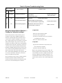
Using the Intensity Select Switches — Finding the Failing Unit at Night . . . . . . . . . . . . . . .
3-3
3-3
3-3
3-3
3-3
3-3
3-3
3-3
3-3
3-3
3-3
3-4
3-4
3-4
3-4
3-5
3-5
3-5
3-5
3-5
3-5
3-5
3-6
3-6
3-6
3-6
3-6
3-7
3-7
3-7
3-7
3-7
3-7
3-8
3-11
3-13
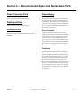
Section 4 — Recommended Spare and Replaceable Parts . . . . . . . . . . . . . . . . . . . . . . . . .
4-1
Customer Service . . . . . . . . . . . . . . . . . . . . . . . . . . . . . . . . . . . . . . . . . . . . . . . . . . . . . . . . . . . . . . .
Ordering Parts . . . . . . . . . . . . . . . . . . . . . . . . . . . . . . . . . . . . . . . . . . . . . . . . . . . . . . . . . . . . . . . . . .
Power Converter Parts . . . . . . . . . . . . . . . . . . . . . . . . . . . . . . . . . . . . . . . . . . . . . . . . . . . . . . . . . . .
Flashhead Parts . . . . . . . . . . . . . . . . . . . . . . . . . . . . . . . . . . . . . . . . . . . . . . . . . . . . . . . . . . . . . . . .
Photocell Parts . . . . . . . . . . . . . . . . . . . . . . . . . . . . . . . . . . . . . . . . . . . . . . . . . . . . . . . . . . . . . . . . . .
Returning Equipment . . . . . . . . . . . . . . . . . . . . . . . . . . . . . . . . . . . . . . . . . . . . . . . . . . . . . . . . . . . .
Repackaging . . . . . . . . . . . . . . . . . . . . . . . . . . . . . . . . . . . . . . . . . . . . . . . . . . . . . . . . . . . . . . . . . . .
Power Converter . . . . . . . . . . . . . . . . . . . . . . . . . . . . . . . . . . . . . . . . . . . . . . . . . . . . . . . . . . . . .
Flashhead . . . . . . . . . . . . . . . . . . . . . . . . . . . . . . . . . . . . . . . . . . . . . . . . . . . . . . . . . . . . . . . . . .
4-1
4-1
4-1
4-1
4-1
4-1
4-1
4-1
4-1
Index . . . . . . . . . . . . . . . . . . . . . . . . . . . . . . . . . . . . . . . . . . . . . . . . . . . . . . . . . . . . . . . . . . . . . . . .
I-1
FTB 324
Revision 8 — 07-17-2002
v
List of Figures
Page
Figure 1-1 View of TB1 Wiring Functions for PC 324 . . . . . . . . . . . . . . . . . . . . . . . . . . . . . . . . . .
1-5
Figure 1-2 PCB1 Pictorial (24740xx) . . . . . . . . . . . . . . . . . . . . . . . . . . . . . . . . . . . . . . . . . . . . . . .
1-6
Figure 1-3 PCB1 Pictorial (24747xx) . . . . . . . . . . . . . . . . . . . . . . . . . . . . . . . . . . . . . . . . . . . . . . . . .
1-7
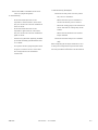
Figure 2-1 PC 324 Power Converter Mounting and Outline . . . . . . . . . . . . . . . . . . . . . . . . . . . . .
2-6
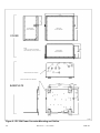
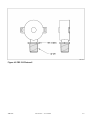
Figure 2-2 FH 324 Flashhead Mounting and Outline . . . . . . . . . . . . . . . . . . . . . . . . . . . . . . . . . .
2-7
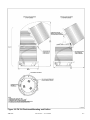
Figure 2-3 PEC 510 Photocell Mounting and Outline . . . . . . . . . . . . . . . . . . . . . . . . . . . . . . . . . .
2-8
Figure 2-4 FTB 324 Single Unit System Installation Wiring . . . . . . . . . . . . . . . . . . . . . . . . . . . . .
2-9
Figure 2-5 FTB 324 Triple Unit System Installation Wiring . . . . . . . . . . . . . . . . . . . . . . . . . . . . .
2-10
Figure 2-6 Recommended Alarm Relay Wiring Protection . . . . . . . . . . . . . . . . . . . . . . . . . . . . . . .
2-11
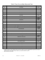
Figure 2-7 PC 324AE Power Converter Internal Wiring . . . . . . . . . . . . . . . . . . . . . . . . . . . . . . . .
2-12
Figure 2-8 PC 324 Power Converter Internal Wiring . . . . . . . . . . . . . . . . . . . . . . . . . . . . . . . . . . .
2-13
Figure 2-9 FH 324 Flashhead Internal Wiring . . . . . . . . . . . . . . . . . . . . . . . . . . . . . . . . . . . . . . . .
2-14
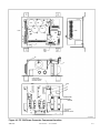
Figure 4-1 PC 324 Power Converter Component Location . . . . . . . . . . . . . . . . . . . . . . . . . . . . . . .
4-3
Figure 4-2 FH 324 Flashhead Component Location . . . . . . . . . . . . . . . . . . . . . . . . . . . . . . . . . . . .
4-4
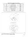
Figure 4-3 PEC 510 Photocell . . . . . . . . . . . . . . . . . . . . . . . . . . . . . . . . . . . . . . . . . . . . . . . . . . . . . .
4-5
List of Tables
Page
Table 1-1 PCB1 24740xx Neon or LED Function Indicators . . . . . . . . . . . . . . . . . . . . . . . . . . . . .
1-2
Table 1-2 PCB1 24740xx Jumper and Switch Settings . . . . . . . . . . . . . . . . . . . . . . . . . . . . . . . . .
1-3
Table 1-3 PCB1 24747xx Neon or Lamp Function Indicators . . . . . . . . . . . . . . . . . . . . . . . . . . . . . .
1-4
Table 1-4 PCB1 24747xx Jumper Settings . . . . . . . . . . . . . . . . . . . . . . . . . . . . . . . . . . . . . . . . . . .
1-4
Table 1-5 Alarm Functions . . . . . . . . . . . . . . . . . . . . . . . . . . . . . . . . . . . . . . . . . . . . . . . . . . . . . . .
1-5
Table 3-1 T1 Transformer Voltages . . . . . . . . . . . . . . . . . . . . . . . . . . . . . . . . . . . . . . . . . . . . . . . . .
3-3
Table 3-2 Checkout of Power Converters with PCB1 24740xx Board . . . . . . . . . . . . . . . . . . . . . .
3-8
Table 3-3 Checkout of Power Converters with PCB1 24747xx Board . . . . . . . . . . . . . . . . . . . . . .
3-10
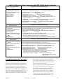
Table 3-4 Selecting the Correct Troubleshooting Guide . . . . . . . . . . . . . . . . . . . . . . . . . . . . . . . . .
3-12
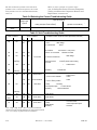
Table 3-5 Unit Troubleshooting Guide . . . . . . . . . . . . . . . . . . . . . . . . . . . . . . . . . . . . . . . . . . . . . .
3-12
Table 3-6 System Troubleshooting Guide . . . . . . . . . . . . . . . . . . . . . . . . . . . . . . . . . . . . . . . . . . . .
3-13
Table 4-1 Power Converter Major Replaceable Parts . . . . . . . . . . . . . . . . . . . . . . . . . . . . . . . . . .
4-2
Table 4-2 Flashhead Major Replaceable Parts . . . . . . . . . . . . . . . . . . . . . . . . . . . . . . . . . . . . . . . .
4-4
vi
Revision 8 — 07-17-2002
FTB 324
Section 1 — FTB 324 Introduction and Operation
System
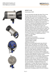
The ElectroFlash™ FTB 324 System is a dual
(white/red) flashing, medium intensity, obstruction lighting system consisting of an FH 324
Flashhead, a PC 324 Power Converter, and a
PEC 510 Photocell with cable.
The power converter provides discharge energy to
the flashhead, and contains components and circuitry to control flashing. The power converter
operates a white light at 40 flashes per minute
during the day. At night, it switches to a red light
at 20 flashes per minute, and turns on steadily-lit
markers. The power converter is usually installed
near ground level.
The FH 324 Flashhead is a dual (white/red) flashhead. Together, the lenses and base enclose the
flashtubes and other interior components.
Latches secure the lenses, which tilt open for
internal access. Position the flashhead to comply
with FAA regulations in Advisory Circular
70/7460-1K, Obstruction Lighting and Marking.
A flashhead cable interconnects the power converter and flashhead. When FTCA Part Number
6340, or equivalent cable, is used, the two may be
separated by up to 600 feet (180 meters). Consult
the factory when a greater separation is necessary.
The photocell is connected directly to the main
panel of the power converter at TB1-1 and TB1-2
to control switching between day and night operation. It can be located up to 100 feet from the
power converter. (Longer distances are possible
with heavier wiring.)
Specifications
Electrical specifications are listed for a single
power converter.
Physical:
PC 324: (H x W x Depth, Wgt.)
14.00 x 16.75 x 8.44 in., 51 lbs.
355.6 x 425.5 x 214.4 mm., 23 kg.
FTB 324
FH 324 Flashhead: (H x Diam, Wgt.)
37.25 x 18.25 in., 31 lbs.
946 x 463 mm., 16.4 kg.
PEC 510 Photocell: (H x W x Depth)
3.06 x 2.58 x 1.02 in.
77.7 x 65.5 x 2.59 mm.
Aerodynamic Wind Area:
Flashhead
1.86 ft.2, .173 m.2
Power Converter
1.63 ft.2, .15 m.2
Environmental:
Complies with FAA specifications in AC
150/5345-43
Performance Characteristics:
Application:
L-865 and L-864
Flash Intensity (nominal):
Day (White)
20,000 ± 25% ECD
Night (Red)
2,000 ± 25% ECD
Default Night (White Backup) 2,000 ± 25% ECD
Beam Spread:
Horizontal: 360º Vertical: 5º
Flash Rate:
Day (White)
40 flashes per minute
Night (Red)
20 flashes per minute
Default Night (White backup) 40 flashes per min.
Electrical:
(Power Converter)
AC Voltage
sine-wave, 120 or 240V, 60 Hz
Volt-Amperes
250 peak
Watts:
Day (White)
130W
Night (Red)
145W
Night (Default White)
55W
Markers (Sidelights)
(each) 116W
System Operation
PCB1 Timing and Trigger Board
PCB1 governs all automatic functions. Two different PCB1 boards are used in the PC 324 Power
Converter. The 24740xx board is used in all except
the “E” models. The 24747xx board is used in the
“E” models. The “xx” in the board’s part number
refers to its dash number, which changes with the
board’s internal programming. The major difference between the two is their jumpers, internal
control and programming. Additionally, PCB1 for
EagleWin “E” systems connects to a telephone
Revision 8 — 07-17-2002
1-1
line for remote monitoring by a computer suing
“Eagle” monitoring software. The factory sets the
jumpers and programs PCB1 before it leaves the
factory.
· An RS-232 socket for internal programming
Refer to Table 1-1 for indicator and lamp functions, and Table 1-2 for jumper settings.
Setting Up PCB1
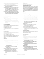
PCB1 24747xx (“Eagle” Board)
PCB1 (24747xx) has the following features:
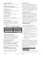
Function Indicators
LED indicators on the PCB1 board signal alarms
and internal functioning. Observe these LEDs to
monitor equipment operations during checkout
and troubleshooting. The essential features on
PCB1 for troubleshooting are shown in Figure 1-2
and Figure 1-3.
·
Twelve LED indicators indicating function
·
One neon lamp indicating trigger power
·
Two jumpers for external programming
·
One RJ11 telephone line socket for remote
EagleWin monitoring
PCB1 24740xx
PCB1 (24740xx) has the following features:
·
LED indicators indicating function
·
A neon lamp indicating trigger power
·
Jumpers for external programming
·
One RS-232 socket for internal programming
Refer to Table 1-3 for indicator and lamp functions, and Table 1-4 for jumper settings.
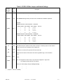
Table 1-1 PCB1 24740xx Neon or LED Function Indicators
Lamp
LED or
Label
Neon
Lamp
Function
NITE ERR
I1
On for incorrect intensity for night operation.
DAY ERR
I7
On for incorrect intensity for day operation.
PEC ALM
I2
Photocell alarm; Power converter failed to switch the day/night mode to the opposite state
within a 19-hour period, perhaps due to its input.
WHT ALM
I8
White alarm; on when a white alarm occurs.
RED ALM
I3
Red alarm; on when a red alarm occurs.
MKR ALM
I9
Marker alarm; on when marker alarm occurs (a marker or markers are out).
FAN
I4
Not used.
SYNC
I 10
Flashes when flash control output is on. Flashes regularly during normal flashing operation
of the power converter.
CONF
I5
Confirm; Flashes after each valid flash.
DAY
I 11
The circuit board is in day mode.
NITE
I6
The circuit board is in night mode.
MKRS
I 12
PCB1 is commanding markers to be on.
NEON
I 13
Trigger power neon; 120VDC trigger power is being supplied to the circuit board.
1-2
Revision 8 — 07-17-2002
FTB 324
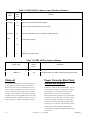
Table 1-2 PCB1 24740xx Jumper and Switch Settings
Jumper
Jumper
or Switch
Label
or
Switch
INT RED
JP1
Uncut (all models).
RES PEC
JP2
Cut in all models to allow usage of a resistive photocell.
ALRMON2
JP3
Uncut.
NOBACK
JP4
Cut to disable white light backup for failure of the red flashhead. Installation dependent.
FAILCLOSE
JP5
Uncut.
Description
†
Selects the marker lamp fail threshold. Chart etched on 24740 board shows “ALARM AT”
thresholds.
MARKER Parameter in Board Software = 4ORLESS
Bulbs Installed SW1-2/MRK1 SW1-1/MRK0
MRK0
SW1-1
0
OFF
OFF
No alarms
2
OFF
ON
One bulb lit
3
ON
OFF
4
ON
ON
Alarm At
Two bulbs lit
Three bulbs lit
MARKER Parameter in Board Software = 5ORMORE
Bulbs Installed SW1-2/MRK1 SW1-1/MRK0
0
OFF
OFF
5
OFF
ON
6
ON
OFF
Five bulbs lit
8
ON
ON
Six bulbs lit
Alarm At
No alarms
Four bulbs lit
MRK1
SW1-2
CT
JP8
Cut to indicate top tier operation for this power converter in a catenary system. If both JP8 and
JP9 are cut or both uncut, operation is for the bottom tier.
CM
JP9
Cut to indicate middle tier operation for this power converter in a catenary system. If both JP8
and JP9 are cut or both uncut, operation is for the bottom tier.
ISOL
JP10
Cut to allow an alarm for only local alarm conditions on this power converter.
Uncut to allow an alarm for local alarms and alarms signalled though a communications
device.
RETROFIT
JP11
Cut to allow the 24740xx Circuit Board to emulate other boards on a tower of mixed circuit
boards.
MARK-
JP12
Uncut — energizes the marker relay in day mode and de-energizes it in night mode.
Cut — de-energizes the marker relay in day mode and energizes it in night mode.
An energized marker relay turns off markers.
REDSENSE
JP13
Cut to enable the usage of sense boards. Uncut to allow usage with laminated transformers
(#8111). For internal design changes. Factory use only.
-
JP14
Uncut; factory use only.
-
JP15
Uncut; factory use only.
ERNO
†
Selects the marker lamp fail threshold. See the chart FOR SW1-1 above in this table.
(Jumpers — OFF=CUT=OPEN)
FTB 324
Revision 8 — 07-17-2002
1-3
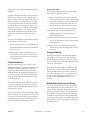
Table 1-3 PCB1 24747xx Neon or Lamp Function Indicators
LED or
Neon
Lamp
Lamp
Label
Function
NITE ERR
I 15
On for incorrect intensity for night operation.
DAY ERR
I9
On for incorrect intensity for day operation.
PEC ALM
I 14
Photocell alarm; Power converter failed to switch the day/night mode to the opposite state
within a 19-hour period, perhaps due to its input.
WHT ALM
I8
On when a white alarm occurs.
RED ALM
I 13
On when a red alarm occurs.
MKR ALM
I7
On when marker alarm occurs (a marker or markers are out).
FAN
I 12
Not used.
SYNC
I6
Flashes when flash control output is on. Flashes regularly during normal flashing operation
of the power converter.
CONF
I 11
Confirm; flashes after each valid flash.
DAY
I5
The circuit board is in day mode.
NITE
I 10
The circuit board is in night mode.
MKRS
I4
PCB1 is commanding markers to be on.
NEON
I3
Trigger power neon; 120VDC trigger power is being supplied to the circuit board.
TD
I1
Modem is in transmit mode.
RD
I2
Modem is in receive mode.
Table 1-4 PCB1 24747xx Jumper Settings
Jumper Label
Jumper—
Board
Name
Description
INT RED
JP2
Not cut (all models).
RES PEC
JP1
Cut to allow PCB1 to recognize a resistive photocell connection.
TEST, LTV, DAY, NITE, RED
TP1 to TP5
Photocell
In a single unit installation, you connect the photocell to TB1-1 and TB1-2 on the main panel of
the PC 324. In a triple-unit installation you connect it to TB1-1 and TB1-2 of the first power converter, the master unit. Other units are slaves.
In triple-unit installations, the first PC 324 is the
one that operates the top flashhead. In triple-unit
installations, TB1-1 and TB1-2 of slave 1 are jumpered together, as is TB1-1 and TB1-2 of slave 2.
Test points for factory use only.
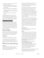
Power Converter Main Panel:
Alarms and Signals
Terminals on TB1 of the PC 324 indicate various
system failures and day or night modes of operation, and they are connected to electrically isolated contacts of relays inside the PC 324.
Electrically isolated contacts are not connected to
any other circuitry. They act as switches rated at
1 ampere 120 VAC, allowing you to connect the
PC 324 to external monitoring equipment. They
change state (for example, from normally closed
(NC) to open or from normally open (NO) to
closed) when the condition indicated on the front
panel occurs.
1-4
Revision 8 — 07-17-2002
FTB 324
Table 1-5 describes the available alarm functions
on TB1 of the power converter.
A synchronization signal to flash the lights
simultaneously.
·
A failure of a top light in night mode causes
·
Master/Slave Interconnect
the master power converter wired to that failing light to signal backup mode to all power
converters; all flashheads on the structure
flash in backup mode (correct night intensity
white back-up). Marker lights are turned off.
The master/slave interconnect terminals at TB1-4
and TB1-5 are connected between power converters in a triple-unit installation. These terminal
connections supply two functions:
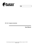
OUTPUT ALARM CONTACTS
INTENSITY SELECT
COMMON
DAY MODE
NIGHT MODE
16
PEC ERROR
15
INTENSITY
ERROR
NIGHT
DAY
18
17
14
13
11
12
COM
10
9
7
6
COM
RED
ALARM
WHITE
ALARM
MASTER/SLAVE
INTERCONNECT
WHT
BLK
4
5
WHT
2
PHOTOCELL
3
BLK
AUTO
1
CONTACTS SHOWN IN
NORMAL OPERATING STATE
(NO ALARMS OR ERRORS)
NIGHT
8
DAY
TB1
THESE ERROR CONTACTS
ARE AVAILABLE ON "A"
(EXTENDED ALARM)
MODELS ONLY
3123AC
Figure 1-1 View of TB1 Wiring Functions for PC 324
Table 1-5 Alarm Functions
Alarm/
System
White
Alarm/all
Function
Connections between TB1-7, and TB1-6 or TB1-8 signal the alarm for improper flash intensity or no
flash at all. The normally open (NO) contacts close and the normally closed (NC) contacts open.
Red
Alarm/all
Connections between TB1-10, and TB1-9 or TB1-11 signal the alarm when the PC 324 detected
improper flash intensity or no flash at all during red night mode operation. The normally open (NO) contacts close and the normally closed (NC) contacts open.
Marker
Alarm/all
Connections between TB5-5, and TB5-4 or TB5-6 signal the alarm under the following conditions:
· One or more marker lamps is not functioning.
· The marker lamp current is too low or not present.
The normally open (NO) contacts close and the normally closed (NC) contacts open.
Intensity
Error/
“A” Option
Signals a day intensity error between TB1-12 and TB1-17 or a night intensity error between TB1-13 and
TB1-17. Error occurs if a flashhead is flashing at the incorrect intensity for the day or night lighting condition determined by the photocell. The normally closed (NC) contacts open.
PEC
Error/
“A” Option
Signals a photocell error between TB1-14 and TB1-17.
The error occurs when the PC has failed to switch from night to day as a result of reading the photocell
circuit within a 19-hour period. This period is factory adjustable. The normally closed (NC) contacts
open.
Day
Mode/
“A” Option
Signals day mode operation between TB1-15 and TB1-17 when the internal operation of the power converter is in day mode. When the signal occurs as it should during daylight, the normally closed (NC) contacts are closed. These contacts open at night.
Night
Mode/
“A” Option
Signals night mode operation between TB1-16 and TB1-17 when the internal operation of the power
converter is in night mode. When the signal occurs as it should during nighttime, the normally closed
(NC) contacts are closed. These contacts open during daylight.
FTB 324
Revision 8 — 07-17-2002
1-5
J16
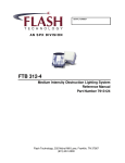
J15
JUMPER
J14
RES
PEC
†
FUNCTION
JP1
INT RED -- Not cut in the PC 324. This jumper is for power
converters with internal controllers for external red beacon lamps.
JP2
RES PEC -- Cut to allow the power converter to use a resistive
JP3
ALRMON2 -- Applies to beacon lamps. Not used in the PC 324.
JP4
NOBACK -- Cut to disable white light backup upon the failure of
the red night flashhead operation.
JP5
FAILCLOSE -- Applies to power converters that use external red
light controllers. Not cut in the PC 324.
photocell. Cut in the PC 324.
INT RED
J1
JP2
JP1
J2
Selects the marker lamp fail threshold. Chart etched on 24740
board shows "ALARM AT" thresholds.
J3
DAY
PEC
WHT
RED
MKR
FAN
SYNC
CONF
DAY
NITE
MKRS
SW1-1
MARKER Parameter in Board Software = 5ORMORE
Bulbs
SW1-2/MRK1 SW1-1/MRK0
Alarm At:
Installed
0
Off
Off
No alarms
5
Off
On
Four bulbs lit
6
On
Off
Five bulbs lit
7
On
On
Six bulbs lit
ALM
LEDs
NITE
ERR
I1
I7
I2
I8
I3
I9
I4
I 10
I5
I 11
I6
I 12
SW1-2
JP8
J4
RS-232
MKR0
MKR1
SW1
NOBACK
ALRMON2
JP10
J5
JP3
FAILCLOSE
JP8
JP15
JP14
JP13
JP5
CT
CM
7740
ISOL
MARKERNO
REDSENSE
JP9
COMPUTER JACK TO SET
JP11
J6
UP BOARD PROGRAMMING
NEON
JP12
J7
I 13
JP14
J11
MRK1 - Selects the marker lamp fail threshold. See the chart
above for SW1-1 (MRK0).
CT -- Cut to indicate top tier operation for this power converter in
a catenary system. If both JP8 and JP9 are cut or both uncut,
operation is for the bottom tier. Internal programming must be set
to CATENARY or RED CAT for this jumper to be operative.
CM -- Cut to indicate middle tier operation for this power converter
in a catenary system. If both JP8 and JP9 are cut or both uncut,
operation is for the bottom tier. Internal programming must be set
to CATENARY or RED CAT for this jumper to be operative.
ISOL -- Cut to allow an alarm for only local alarm conditions on
this power converter. Not cut to allow an alarm for local alarms
and alarms signaled to this power converter through a
communications bus wire.
RETROFIT -- Cut to allow the 4740 board to emulate other boards
on a tower of mixed circuit boards. The parameter RETROFIT
TYPE in internal programming on the 4740 must also be set to
the board type that the 4740 is to emulate: 7413, 7740-CMOS, or
7740-PLD.
MARKERNO -- Uncut to energize the power converter marker
relay during the day and de-energize it at night. Cut to
de-energize the power converter marker relay in day mode and
energize it at night.
REDSENSE -- Cut to enable the 4740 board to be used with
JP13
J17
J12
MARKER Parameter in Board Softwere = 4ORLESS
Bulbs
SW1-2/MRK1 SW1-1/MRK0
Alarm At:
Installed
0
Off
Off
No alarms
2
Off
On
One bulb lit
3
On
Off
Two bulbs lit
4
On
On
Three bulbs lit
J10
J9
sense boards. Uncut to allow use with laminated transformers
(#8111). This refers to internal design changes. Factory use only.
Unused -- Factory use only.
J8
JP15
†
Unused -- Factory use only.
JUMPERS -- OFF=CUT=OPEN
Function
LED Indicator
NITE ERR -- On for a night intensity error.
I1
DAY ERR -- On when a day intensity error occurred (the light flashed at an incorrect intensity).
I7
PEC ALM -- On for photocell alarm (photocell failed to switch state within 19 hours).
I2
WHT ALM -- On when a white alarm occurs (white light failed).
I8
RED ALM -- On for a red alarm (a red light failure occurred).
I3
MRK ALM -- On when a marker alarm occurs (a marker or markers are out).
I9
FAN -- Not used.
I4
SYNC -- Flashes when flash control is present on the master/slave interconnect line.
I 10
CONF -- (Confirm) Flashes after the timing and trigger board detects a valid flash.
I5
DAY -- On when the power converter is in day mode.
I 11
NITE -- On when the power converter is in night mode.
I6
MKRS -- On when PCB1 is commanding markers to be on.
I 12
TRIGGER POWER NEON -- On when the 120VDC trigger power circuit for the flashhead is
I 13
active.
4740
Figure 1-2 PCB1 Pictorial (24740xx)
1-6
Revision 8 — 07-17-2002
FTB 324
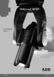
12
12
12
CONNECTOR
12
RS-232
FUNCTION
Computer cable connector used to program
the circuit board at the factory.
J16
J15
J13
J14
J12
RJ11
JUMPER
JP1
Telephone line connector.
JUMPER
JP1
JUMPER
resistive photocell. Cut on the PC 324.
JP2
RES PEC
J1
GND
INT
RED
FUNCTION
Cut to use the power converter with a
JP2
INT RED -- Cut to use the internal red
controller of the power converter. Not cut in
the PC 324.
J2
FUNCTION
LED/LAMP
+5V
I 15
I9
LEDs
NITE
DAY
PEC
WHT
RED
MKR
FAN
SYNC
CONF
DAY
NITE
MKRS
DAY ERR -- On for day intensity error.
I 14
PEC ALM -- On for PEC alarm.
I8
WHT ALM -- On for white alarm.
I 13
ERR
I 15
I9
I 14
I8
I 13
I7
I 12
I6
I 11
I5
I 10
I4
ALM
+24V
J3
NITE ERR -- On for night intensity error.
I7
RED ALM -- On for red alarm.
MKR ALM -- On for marker alarm.
I 12
FAN -- Not used.
I6
SYNC -- Flashes when flash control output is
on.
CONF -- (Confirm) Flashes after the PCB1
I 11
board detects a valid flash.
I5
DAY -- On when in day mode.
I 10
NITE -- On when in night mode.
TEST
I4
TX
MKRS -- On when the board is commanding
markers to be on.
CARRIER
NEON -- On when 120VDC from the power
RED
RX
I3
J4
NITE
DAY
transformer is applied to PCB1.
I2
RD -- Modem is receiving a signal.
I1
TD -- Modem is transmitting a signal.
LTV
J5
COMPUTER
PHONE CONNECTOR
1
F1
RS-232
J18
CONNECTOR
J17
J8
RJ 11
4
NEON
J6
J7
I3
474732
Figure 1-3 PCB1 Pictorial (24747xx)
FTB 324
Revision 8 — 07-17-2002
1-7
This page is intentionally blank.
1-8
Revision 8 — 07-17-2002
FTB 324
Section 2 — Outline, Mounting, Installation
Unpacking
Inspect shipping cartons for signs of damage
before opening them. Check package contents
against the packing list and inspect each item for
visible damage. Damage claims should be
reported promptly to the freight handler.
Tools
Although no special tools are necessary, FTCA
suggests the following tools for installation and
maintenance:
· #2, flat-blade screwdriver
· 5/16 inch, flat blade screwdriver
· #2, Phillips® 9-inch shank screwdriver
· Set of combination wrenches
· Medium, slip joint pliers
· Long-nose pliers
· 8- or 10-inch adjustable wrench
· Triplett ™ Model 630-NA VOM, or equivalent,
analog volt-ohm meter
Wait one minute for storage capacitors to drain
down. Open the flashhead and use a voltmeter to
check that no voltage potential exists between the
red and the blue wires. Look for these wires on
the ceramic terminal posts.
You may pivot the lens open by disengaging
quick-release latches. Be careful when opening
the lens to ensure that it does not strike adjacent
objects. Two lanyard cables secure the lens to the
flashhead.
Mountings
Power Converter
Mounting and outline dimensions for the power
converters are shown in Figure 2-1. Use the following guidelines for mounting the power converter:
· Ensure that adequate space exists around the
equipment for access during installation,
maintenance and servicing.
· Allow space for air flow around the power converter.
· Multi-purpose crimp tool
· You must use a bonding strap on a bolt
through the power converter case leg. Connect
the strap to the site grounding system.
Access
WARNING
STOP: Before proceeding—read warning on Page iii. Disconnect the primary
power before opening the power converter enclosure or flashhead.
Power Converter
Quick-release latches secure the cover. When you
release these you can open the cover for internal
access.
FTCA does not furnish mounting hardware unless
you order it as part of an installation kit.
Flashhead
Mounting and outline dimensions for the flashhead are shown in Figure 2-2. Protect the flashhead from lightning strikes. The flashhead may
be mounted to painted or unpainted surfaces. Use
the following guidelines:
Flashhead
The flashhead normally contains no interlock. Do
not open the flashhead unless you have disconnected primary power from the power converter.
FTB 324
·
Use a lightning rod extended above the flashhead to protect it when it is mounted at the
uppermost part of the structure.
Revision 8 — 07-17-2002
2-1
·
Avoid locating a lightning rod where it would
prevent tilting the lens open or interfere with
access by maintenance or service personnel.
·
Use a bonding strap when mounting the flashhead to the structure, and fasten the bonding
strap to the flashhead with the mounting bolt
that goes through the leg that contains the
ground connection.
Leveling
The flashhead must be level for correct vertical
beam alignment. Two leveling vials are permanently attached to the flashhead assembly. When
the flashhead is level, bubbles in both leveling
vials are centered. For leveling, use the following
guidelines:
· If adjustment is necessary, raise the appropriate mounting foot with shims or washers.
Raising one foot by 1/16 inch (1.6 mm) tilts the
beam about 1/2 degree.
· Take extreme care to ensure that all four feet
rest snugly against a firm mounting surface
before tightening the mounting bolts. Failure
to do so could result in serious damage to the
base when you tighten the bolts.
Photocell
Mounting and outline dimensions for the photo-
Installation Wiring
NOTE
Only general information for a typical installation
is presented here, and more specific information
may be needed for your site. In particular,
because the L-810 marker (side-light) lighting
components for red nighttime lighting are often
purchased from others, and have many variations, only general hook-up information for flashing and monitoring the red lights is included.
This manual may not contain all the information
about installation wiring required for your site.
Consult any installation drawings prepared especially for your site or supplied with the equipment. Site installation drawings should take
precedence.
Also note that FTCA wiring diagrams define minimum requirements recommended for satisfactory
equipment operation. These minimum requirements may not be enough, by themselves, to comply with local electrical codes. It is the
responsibility of the installer to comply with all
applicable electrical codes.
Consider the following wiring: power service,
marker lights, power converter, master/slave
interconnect, and the flashhead.
cell are shown in Figure 2-3. Use the following
guidelines:
All installation wiring should have an insulation
rating of 600 volts or higher.
· Locate the photocell where it has an unob-
You can find conduit and other distribution wiring details on electrical installation diagrams provided by FTCA or others.
structed view of the polar sky.
· It must not view direct or reflected artificial
light.
· The photocell may be supported directly by
electrical conduit.
· Mount the photocell vertically on the top end of
a vertical length of conduit to prevent water
from entering and damaging the unit.
Red Light Fixtures
Obtain outline, clearance and mounting details
for L-810 markers from separate drawings provided by FTCA (or others). This manual does
not contain information about installing red
markers.
2-2
FAA Advisory Circular 70/7460-1K gives the
lighting requirements for various types of structures.
Power Converter Wiring
Power Service Wiring
Power service wiring must be sized to satisfy the
load demand of the red light markers and the
power converters. Each marker lamp draws 116
watts. Night operation of each power converter
Revision 8 — 07-17-2002
FTB 324
requires 250 volt-amperes. See Specifications in
Section 1.
A typical installation has three power converters
and two tiers of markers. Thus, the last slave
power converter connected together in a chain of
units is connected to a flashhead only—no markers are connected to this unit. Each steady-burning marker draws approximately 1 ampere. To
determine wire gauge, consider the total ampere
load and the length of the run. Please read the
notes on the installation wiring diagrams supplied both in this manual and with the equipment.
Please note that FTCA recommends the following
guidelines for red light wiring:
·
Using a maximum wire size of #12 AWG from
the red light module terminal block inside the
power converter
1. Run the cable along one of the tower legs and
wrap one full turn of two-inch Scotchrap™ #50
tape, or the equivalent, around the cable and
tower leg at 5-foot (minimum) intervals (1.5
meters). Space the cable one inch away from
direct contact with a leg flange or and edge.
2. Wrap three full turns of one-inch Scotchrap
Filament #890 tape, or the equivalent, over
the Scotchrap #50 tape.
3. Wrap four full turns of two-inch Scotchrap #50
tape, or the equivalent, over the Scotchrap Filament #890 tape.
4. Perform steps 1 through 3 also directly above
and below any tower leg flanges that the cable
may cross.
· Running a short length of #12 AWG wire to a
junction box near the power converter when
load requirements call for heavier gauge wire
to red light fixtures.
Flashhead Wiring
The wiring between the power converter and
flashhead requires five conductors with 600 volts
(minimum) insulation. Two of the conductors
must be #10 AWG. The other three may be #16
AWG (minimum; for mechanical strength) if you
are cabling together individual wires. FTCA recommends using FTCA Part Number 6340 cable
for this application.
To ensure reliable operation, FTCA recommends
continuous wiring between the power converters
and their associated flashheads without intervening junctions or splices.
If you use FTCA Part Number 6340 cable without
electrical conduit, you should secure it to the main
structure not more than 5 feet (1.5 meters) below
the flashhead and at 5-foot (minimum) intervals
between the flashhead and power converter.
FTB 324
Securing the Cable
Use the following method for securing the flashhead cable to a skeletal structure:
Photocell Wiring
For triple-unit lighting, each individual lighting
unit requires a power converter and flashhead,
but the photocell is connected to only one unit in a
triple-unit. This unit is called the master unit, the
others are called slaves.
Connect the photocell to TB1-1 and TB1-2 on the
master power converter. The photocell terminals
TB1-1 and TB1-2 on the slave power converters
are jumpered together. Also, you connect the master unit (to which the photocell is directly connected) to the top flashhead and top tier of
markers.
Master/Slave Interconnect Wiring
In a triple-unit system, the master unit and slave
units communicate over the “master/slave” interconnect wiring. The master and slave power converters are connected together for communication
at the master/slave interconnect terminals TB1-4
and TB1-5 on the main panel. The recommended
size wiring for this purpose is #16 AWG. Twist the
wires together to form a twisted pair at the rate of
12 twists per foot.
Revision 8 — 07-17-2002
2-3
6. Marker Mounting (Sidelights):
Alarm Relay Wiring
The wiring for alarm relay connections in Figure
2-6 minimizes the possibility of damage caused by
high voltage transients.
· Ensure that marker junction boxes are
mounted with the weep holes down.
· Ensure that the junction boxes are water
tight.
Installation Checklist
7. Power Converter Wiring
Examine the installation drawings and use
Complete the following steps before applying
power to the lights.
the following checks:
1. Inspect all equipment for damage.
·
·
Wire each unit according to the instructions.
2. Verify the received equipment against the
packing list to ensure completeness.
·
In triple installations, all power convert-
·
Check all electrical connections for tight-
·
Check all terminal strip connections for
·
Ground the power converter case to the
·
Wires at TB1-4 and TB1-5 should be
3. Power Converter Mounting:
Position and mount each unit correctly, allowing adequate clearance for opening the covers.
Use the following checks:
· Ensure that the case is mounted upright,
is water tight, and grounded.
· Check hardware inside the case to ensure
that the mounting screws and nuts are
tight.
· Ensure that only the bottom of the case
has drain holes and that they are clear.
· Ensure that no holes are punched or
drilled on the top surface of the case.
· Ensure that air can flow around the case.
· Mount the power converter away from
ers must be wired to the same electrical
phase. Wire all three power converters to
one 20-amp. circuit breaker.
ness.
tightness.
site lightning ground system.
daisy-chained as a twisted pair between
the master power converter and the slave
units. The rate of twist is 12 per foot. If a
shielded cable is used, ground the shield.
Ensure that TB1-4 is connected to all
TB1-4 connections on all units, and TB1-5
is similarly connected.
8. Flashhead Wiring
radio frequency interference (RFI).
· Protect the top flashhead against light-
4. Flashhead Mounting
ning strikes.
· Ensure that the flashhead lens can be
opened without striking other objects.
· Level and aim the flashhead.
· Ground the flashhead.
· Check the wiring of the flashhead cable to
the flashhead.
· Secure the flashhead cable to the tower.
5. Photocell Mounting
Support and tape the flashhead cable to
prevent its movement by the wind.
· Locate photocell where it views unobstructed polar sky with no direct or
reflected artificial lighting striking it.
· Mount the photocell vertically on the top
9. Photocell Wiring
· Connect the photocell to the master power
end of a vertical length of conduit to prevent water from entering the unit.
2-4
Check for proper incoming service voltage.
Revision 8 — 07-17-2002
converter: the black wire to TB1-1 and the
white wire to TB1-2.
FTB 324
· Ensure that TB1-1 and TB1-2 on the slave
units are jumpered together.
· Ensure that each power converter powers
10. Alarm Wiring
·
only one tier of markers.
If external alarm detection circuit
·
responds to closed contacts, ensure that
they are wired to the contacts on TB1 that
close on alarm.
·
·
Ensure that the top tier of markers is
wired to the master power converter.
·
Check the wiring gauge to the markers to
responds to open contacts, ensure that
they are wired to the contacts on TB1 that
open on alarm.
·
Ensure that all markers have all their
Alarm wiring should be lightning and RFI
· Ensure that marker lamps are 116 Watts
If external alarm detection circuit
protected: shielded, grounded shield, and
in a conduit.
·
11. Marker Wiring (Sidelights)
If a specific alarm is ganged together from
all power converters as one, ensure that
the wiring follows local installation
instructions.
FTB 324
ensure less than 3% voltage drop at the
sockets
lamps installed.
only.
After completing all the steps listed above, turn
on the power and perform an operational checkout from procedures in Section 3 of this manual.
Revision 8 — 07-17-2002
2-5
(425.5)
5.00
(127)
LEFT SIDE VIEW
AS WALL MOUNTED
FRONT VIEW
AS WALL MOUNTED
(356)
COVER
NOTES:
1. Weight = 50.5 pounds ( 22.9 kilograms)
2. Max. wind loading = 1.63 sq. ft. (.152 sq. m.)
.875
(22.2)
.875
(22.2)
BOTTOM VIEW AS WALL MOUNTED
(214)
BOTTOM VIEW
AS WALL MOUNTED
1.06
(27)
(170)
1.06
(27)
.344
(8.74)
.875
(22.2)
REAR OF CHASSIS AS WALL MOUNTED
(311)
(54.9)
Ø .44 INCH
(11.2)
BASEPLATE
(127)
15.2
(386)
Ø.44 INCH
(11.2)
312MO
Figure 2-1 PC 324 Power Converter Mounting and Outline
2-6
Revision 8 — 07-17-2002
FTB 324
FH324MO
Figure 2-2 FH 324 Flashhead Mounting and Outline
FTB 324
Revision 8 — 07-17-2002
2-7
2.58 (65.5)
2.28 (57.8)
1.02 (25.9 )
0.10 (2.54)
0.375 (9.53)
1.92 (48.8)
3.06 (77.7)
0.33 (8.38)
HEX 1.0 (25.4)
0.125 (3.18)
NOTE: ALL DIMENSIONS ARE IN INCHES (MILLIMETERS)
1/2" NPT
PEC510MO
Figure 2-3 PEC 510 Photocell Mounting and Outline
2-8
Revision 8 — 07-17-2002
FTB 324
RED
RED
NOTES:
8. FTCA RECOMMENDS #12 AWG AS THE MAXIMUM CONDUCTOR
1. THE AC INPUT POWER CONDUCTOR SIZE DEPENDS ON THE SERVICE
VOLTAGE, THE DISTANCE FROM THE SOURCE, THE NUMBER OF
SIZE FROM TB5 TO THE JUNCTION BOX. USE LARGER
POWER CONVERTERS, AND THE NUMBER OF L-810 MARKER LIGHTS
CONDUCTORS FOR THE BRANCH FROM THE JUNCTION BOX
SERVED. USE 250 VA PER POWER CONVERTER PLUS 116 VA PER
TO THE MARKER FIXTURES, IF REQUIRED. SEE NOTE 9 TO
BLU
BLU
SUPPLY LIGHTNING
PROTECTION FOR THE
DETERMINE THE BRANCH CONDUCTOR SIZE.
L-810 MARKER LIGHT. ALSO SEE NOTE 9.
BLK
TOP FLASHHEAD
BLK
9. THE TOTAL LINE DROP, INCLUDING INPUT SERVICE WIRING
2. USE A CONTINUOUS CABLE FROM THE POWER CONVERTER
AND BRANCH LINES TO THE L-810 MARKER LIGHT SOCKETS,
TO THE FLASHHEAD WITHOUT JUNCTIONS OR SPLICES.
FLASHHEAD
CABLE CHART
MUST NOT EXCEED 3% OF RATED VOLTAGE.
3. CONTACT RATING 1 AMPERE, 120 VAC. EXTENDED MONITORING IS
10. THE MARKER FIXTURES MAY BE SUPPLIED BY OTHERS.
AVAILABLE ON FTB 324 SYSTEMS ONLY ("A" MODELS).
4. USER'S ALARM CIRCUITS NOT SHOWN.
11. MOUNT THE POWER CONVERTER VERTICALLY.
5. USE LINE 1 AND NEUT FOR 120V, 60 Hz;
12. INSERT TELEPHONE PLUG INTO SURGE SUPPRESSOR
USE LINE 1, LINE 2 AND NEUT FOR 240/120V, 60 Hz.
MINIMUM REQUIREMENTS
FOR USER'S CABLE
MODULE LOCATED NEAR CONDUIT HOLES.
6. UNIT IS FACTORY WIRED FOR NAMEPLATE VOLTAGE.
13. BOND CASE TO THE SITE GROUNDING SYSTEM.
7. JUNCTION BOX FOR DISTRIBUTION WIRING TO MARKERS
TYPICALLY FURNISHED BY OTHERS AND LOCATED AS CLOSE AS
POSSIBLE TO THE POWER CONVERTER.
RED
#10 AWG
BLU
BLK
WHT
PUR
#10 AWG
#16 AWG
#16 AWG
#16 AWG
WHT
WHT
PUR
PUR
SHIELD
GND
MIN. INSULATION 600V
COLORS FOR REF. ONLY
RED
PC 324 POWER CONVERTER
RED
NOTE 11
BLU
F5
BLU
AND MOUNT IT
AUTO
VERTICALLY AT THE TOP
INTENSITY
SELECT
END OF A VERTICAL
LENGTH OF CONDUIT TO
WHT
MRKS
RED
NOTES
3&4
EXTENDED
BLK
WHT
PUR
TB2
1 ANODE
2
3 CATHODE
4 TRIG 1
5 TRIG RTN
6 TRIG 2
WHT
GND
PUR
NOTES
3&4
GND
F1
FTCA PN 6340 OR USER'S CABLE
INPUT
(SEE CABLE CHART)
POWER
TYPICAL MARKER
TIER L-810'S
GND
TB4 1 2 3
NOTE 10
NOTE 5
NOTE 12
MONITORING
NOTE 1 & 5
TWO CONDUCTORS
(#16 AWG MINIMUM)
NOTE 9
LINE 1
PRIMARY NEUT
POWER LINE 2
(NOTE 6)
SHIELD
SHIELD
GND
SHIELD
BLK
PUR
L1
COMMON
TEMP SENSE
TB1 1 2 3 4 5 6 7 8 9 10 11 12 13 14 15 16 17 18
NIGHT MODE
PEC ERROR
DAY MODE
INTENSITY
DAY
BLU
ERRORNIGHT
REDCOM
ALARM
WHITECOM
ALARM
BLK MASTER/SLAVE
WHT INTERCONNECT
PHOTOCELL
NEUT
123456
ENTERING THE UNIT.
BLK
BLK
WARNING
PREVENT WATER FROM
PHOTOCELL
F4
HV
OUTPUT ALARM CONTACTS
CONTACTS SHOWN IN NORMAL
OPERATING STATE
(NO ALARMS OR ERRORS)
NIGHT
N
DAY
L2
MOUNT THE PHOTOCELL
TO FACE THE POLAR SKY
WHT
Revision 8 — 07-17-2002
Figure 2-4 FTB 324 Single Unit System Installation Wiring
FTB 324
FH 324 FLASHHEAD
NOTE 8
NOTE 7
NOTE 2
GND
NOTE 13
SURGE SUPPRESSED TELEPHONE LINE CONNECTION FOR A REMOTE COMPUTER AND EAGLEWIN SOFTWARE
2-9
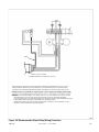
18AE
DENOTES WIRE SPLICE CONNECTIONS
RED
RED
RED
NOTES:
1. AC INPUT POWER CONDUCTOR SIZE DEPENDS ON THE SERVICE VOLTAGE, THE DISTANCE FROM
BLU
THE SOURCE, THE NUMBER OF POWER CONVERTERS AND NUMBER OF L-810 MARKER LIGHTS
SERVED. USE 250 VA PER POWER CONVERTER PLUS 116 VA FOR EACH L-810 MARKER LIGHT.
ALSO SEE NOTE 9.
2. USE A CONTINUOUS CABLE FROM THE POWER CONVERTER TO THE FLASHHEAD WITHOUT
WHT
FLASHHEAD
CABLE CHART
WHT
PUR
6. UNIT IS FACTORY WIRED FOR NAMEPLATE VOLTAGE.
7. OTHERS TYPICALLY FURNISH THE JUNCTION BOX FOR DISTRIBUTION WIRING TO THE MARKERS.
WHT
PUR
PUR
BLU #10 AWG
BLK #16 AWG
SHIELD
LOCATE THE JUNCTION BOX AS CLOSE AS POSSIBLE TO THE POWER COVNERTER.
BLK
FOR USER'S CABLE
RED #10 AWG
PUR
BLU
WHT
MINIMUM REQUIREMENTS
4. USER'S ALARM CIRCUIT NOT SHOWN.
5. USE LINE 1 AND NEUT FOR 120V, 60 Hz; USE LINE1, LINE 2 AND NEUT FOR 240/120V, 60Hz.
RED
BLU
BLK
BLK
JUNCTIONS OR SPLICES.
MODELS ONLY.
USE LIGHTNING
PROTECTION FOR THE
TOP FLASHHEAD
BLU
BLK
3. CONTACT RATING 1 AMPERE, 120 VAC. EXTENDED MONITORING IS AVAILABLE ON THE 324- "A"
SHIELD
WHT #16 AWG
8. FTCA RECOMMENDS USING #12 AWG AS THE MAXIMUM CONDUCTOR SIZE FROM TB5 TO THE
GND
PUR #16 AWG
GND
JUNCTION BOX. USE LARGER CONDUCTORS FOR THE BRANCH FROM THE JUNCTION BOX TO
THE MARKER FIXTURES, IF REQUIRED. SEE NOTE 9 TO DETERMINE THE BRANCH CONDUCTOR
SIZE.
MIN. INSULATION 600V
COLORS FOR REF. ONLY
RED
RED
9. THE TOTAL LINE DROP, INCLUDING THE INPUT SERVICE WIRING AND BRANCH LINES TO THE
L-810 MARKER LIGHT SOCKETS, MUST NOT EXCEED 3% OF THE RATED VOLTAGE.
RED
RED
10. MARKER FIXTURES MAY BE SUPPLIED BY OTHERS.
BLU
BLU
11. MOUNT THE POWER CONVERTER VERTICALLY.
12. TERMINALS AT TB1-1&2 MUST BE JUMPERED ON SLAVE UNITS.
BLU
BLU
13. BOND THE CASE TO SITE GROUNDING SYSTEM.
WHT
WHT
WHT
PUR
BLK
MOUNT THE PHOTOCELL
WHT
PUR
BLK
NOTE 10
NOTE 10
UPR
PUR
VERTICALLY AT THE TOP
TYPICAL MARKER TIER L-810S
BLK
TYPICAL MARKER TIER L-810'S
BLK
END OF A VERTICAL LENGTH
OF CONDUIT TO PREVENT
SHIELD
SHIELD
SHIELD
SHIELD
GND
GND
WATER FROM ENTERING THE
UNIT. FACE IT TOWARD THE
POLAR SKY.
FTCA PN 6340 OR USER'S CABLE
(SEE CABLE CHART)
FTCA PN 6340 OR USER'S CABLE
(SEE CABLE CHART)
PC 324 POWER CONVERTER (MASTER)
PC 324 POWER CONVERTER (SLAVE)
OUTPUT ALARM CONTACTS
OUTPUT ALARM CONTACTS
F5
HV
DAY
WARNING
NOTES
3&4
LAST SLAVE UNIT
TB2
GND
NOTE 12
EXTENDED
MONITORING
3CATHODE
WHT
4
VIO
5TRI GRTN
6 TRIG 2
CONNECTED TO THE
NOTES
3&4
TRIG 1
MASTER UNIT AND
FIRST SLAVE UNIT.
F1
GND
INPUT
POWER
SHIELD
TB4 1 2 3
N
COMMON
NIGHT MODE
DAY
INTENSITY
NOTES
3&4
MARKERS ARE
GND
BLK
L1
N
TB1 1 2 3 4 5 6 7 8 9 10 11 12 13 14 15 16 17 18
L2
TB4 1 2 3
NOT HAVE MARKERS.
123456
L2
BLK
INPUT
POWER
SHIELD
(NOT SHOWN) DOES
MRKS NEUT
1 ANODE
BLU 2
TEMP SENSE
F1
GND
RED
ERRORNIGHT
5TRI GRTN
6 TRIG 2
INTERCONNECT
4 TR I G 1
NOTE 9
COM WHITE
ALARM
NOTES
3&4
MASTER/SLAVE
GND
3 CATHODE
WHT
123456
1 ANODE
2
PHOTOCELL
VIO
F4
INTENSITY
SELECT
MRKS NEUT
L1
COMMON
BLK
WHT
TEMP SENSE
TB1 1 2 3 4 5 6 7 8 9 10 11 12 13 14 15 16 17 18
BLU
NIGHT MODE
INTENSITY
DAY
ERRORNIGHT
RED
PHOTOCELL ERROR
DAY MODE
COM RED
ALARM
INTERCONNECT
WHT
COM WHITE
ALARM
MASTER/SLAVE
BLK
WHT
PHOTOCELL
TB2
HV
WARNING
AUTO
F4
INTENSITY
SELECT
PHOTOCELL ERROR
DAY MODE
AUTO
PHOTOCELL
F5
CONTACTS SHOWN IN NORMAL
OPERATING STATE
(NO ALARMS OR ERRORS)
NIGHT
BLK
NIGHT
COM RED
ALARM
CONTACTS SHOWN IN NORMAL
OPERATING STATE
(NO ALARMS OR ERRORS)
WHT
DAY
BLK
Revision 8 — 07-17-2002
Figure 2-5 FTB 324 Triple Unit System Installation Wiring
2-10
FH 324 FLASHHEAD
FH 324 FLASHHEAD
GND
EXTENDED
MONITORING
NOTE 5
NOTE 5
NOTE 9
NOTE 7
TWO CONDUCTORS
(#16 AWG MINIMUM)
NOTE 13
NOTE 7
NOTE 11
NOTE 11
NOTE 13
NOTE 8
NOTE 8 NOTE 2
NOTE 2
DENOTES WIRE
TWO (2) #16 AWG 600V MIN
SPLICE CONNECTIONS
CONDUCTORS TWISTED TOGETHER
NOTE 1 & 5
PRIMARY POWER
FROM SINGLE 20A
BREAKER
(NOTE 6)
TO
LAST
NOTE 1 & 5
SLAVE
LINE 1
UNIT
NEUT
LINE 2
GND
LAST SLAVE UNIT (NOT
SHOWN) HAS SIMILAR
POWER AND FLASHHEAD
NOTES 1 & 5
WIRING
(TYPICALLY, ONE MASTER AND
TWO SLAVES ARE CONNECTED
TOGETHER AT TB1-4 AND TB1-5.)
20AE
FTB 324
MASTER/SLAVE INTERCONNECT
LINE TO ADDITIONAL SLAVE UNIT
ALARM
130VAC
MOV
GND
SHIELD
METALLIC CONDUIT
CUSTOMER CONNECTION TO ALARM RELAY CONTACTS
FLASH TECHNOLOGY ALARM RELAY CONTACTS ARE PROTECTED FROM VOLTAGE TRANSIENTS OF UP TO 1000 VOLTS.
HOWEVER, WIRED ALARM CONTACTS CAN BE SUBJECTED TO VOLTAGES GREATER THAN 1000 VOLTS BECAUSE OF
LIGHTNING. THE FOLLOWING RECOMMENDATIONS MINIMIZE THE POSSIBILITY OF DAMAGE CAUSED BY HIGH VOLTAGE
NOTES:
.1
2.
USE SHIELDED CABLE TO ATTACH FLASH TECHNOLOGY ALARM RELAY CONTACTS TO EXTERNAL EQUIPMENT.
ATTACH THE SHIELD WIRE TO A GND (GROUND) TERMINAL ON THE FLASH TECHNOLOGY POWER CONVERTER AS SHOWN.
3.
WHEN POSSIBLE, ROUTE ALARM CONTACT WIRING IN METALLIC, GROUNDED CONDUIT.
4.
FOR ADDITIONAL PROTECTION, ADD MOVs (VARISTORS) FROM EACH ALARM RELAY CONTACT TERMINAL TO A GND
TERMINAL AT THE FLASH TECHNOLOGY POWER CONVERTER.
ALRM2
Figure 2-6 Recommended Alarm Relay Wiring Protection
FTB 324
Revision 8 — 07-17-2002
2-11
2-12
NOTE:
2
1
2
1
WHT/YEL
YEL
GRN
VIO
BLU
W HT/BLU
2
1
8
5
3
1
GND
FAN NO
G ND
FH CABLE WHT
6
120 VAC
4
2
TRIGGER XFMR
FH CABLE VIO
G ND
Revision 8 — 07-17-2002
2
BLU
RES. PHOTOCELL
DAY MODE
COMMON
2
3
WHITE ALARM NO
WHITE ALARM COM
3
TB1
3
WHT/GRY
RED
9
10
11
WHT/VIO
ORN
GRY
VIO
WHT
BLK
WHT/YEL
YEL
12
ORN
8
13
14
15
RED
7
WHT/BRN
6
16
17
18
WHT/ORN
WHT/GRN
TEST
(BOTTOM VIEW)
KEY WAY
WHT/BLU
5
WHT/ORN
4
BLU
2
WHT/GRN
1
BRN
3
2
1
S2
INTENSITY
QC6
TRANSFORMER
WHT/BRN
WHT/YEL
WHT/VIO
WHT/BLU
WHT/BLK
WHT/GRN
WHT/BRN
G4C
QC5
QC4
G RN
G
RS485
YEL
BLU
GRN
SEE NOTE 1
2
MARKER ALARM NO
MARKER ALARM COM
J9
1
G4A
T3
COUPLING
T1
GRN
BRN
ORN
VIO
GRY
WHT/BLU
BLU
GRN
WHT/GRN
RED
WHT/GRN
WHT/ORN
QC7
TB1
NITE INTENSITY2
ERROR
1
3
J4
J3
REV C
3-8451-37
REDN/ODAY
5
MODE
COM 6
N/C 4
COM 3
N/O 2
N/C 1
N/O 5
N/C 4
COM 6
PEC
FAIL
COM 3
PCB5
ALARM
RELAY
BOARD
DAY MODE2
NITE INT ERROR3
J2
ORN
WHT/GRN
WHT/RED
NITE
N/O 2 WHT/ORN
MODE
N/C 1
ORN
RED
DAY MODE ERROR1
YEL
RED
DAY INTENSITY
ERROR
RELAY
WHT/BLU
NITE MODE4
COM5
K3
DISCHARGE
PEC FAIL6
J1
G4C
WHT/GRN
MARKER ALARM NC
WHT/VIO
WHT/BLK
WHT/BLU
WHT/BRN
WHT/GRN
SENSE
PCB4
RED TRANSFORMER
RED
MODE RELAY
K2
RED
J7
1
J6
8
7
6
WHITE ALARM NC
TRIGGER POWER
TRIGGER OUT
TRIGGER RETURN
5
4
COMMON
3
NITE RELAY
2
1
J5
6
5
4
PHOTOCELL
COMMON
2
3
WHT/YEL
WHT
BLK
WHT/RED
BLU
MODE SELECT
PHOTOCELL FAIL
COMMON
NITE MODE
1
J4
6
5
4
WHT/RED
RED
WHT/BRN
WHT/VIO
WHT/ORN
WHT/VIO
QC2
BLU
NITE INTENSITY ERROR
SENSE POWER IN
DAY INTENSITY ERROR
GND
FLASH CONTROL
COMMON
3
1
24 VAC N
STROBE SENSE
24 VAC P
J3
3
2
RED ALARM NO
RED ALARM COM
1
RED ALARM NC
WHT/BLK
WHT/GRY
9
9
WHT/GRN
SURGE SUPPRESSOR
7
6
8765
6 7 85
5
G4D
WHT/GRN
LS1
FAN COM
4
3
YEL
2
RESISTOR
DISCHARGE
PHONE LINE
1
1
TB2
L2
BLU
BLU
ALARM
OPTIONAL
BURST
C2B
C2C
C2D
C2A
C3
R2B
RESISTOR
BURST
CHOKE
E4
R2A
WHT/YEL
RED
HV
WARNING
L1
RED
FLASHCHOKE
E
1
J18
1
5
43
6
BLU
J8
WHT/ORN
2
J2
BLK
PCB1
2
BEACON SENSE
RED
2
234
WHT/GRN
TRIGGER
J11
COMMON
WHT
WHT/YEL
1
WHT/BLU
TIMING AND
GRY
WHT/BRN
WHT/BLK
WHT/RED
WHT/BRN
3
WHT/RED
2
BRN
1
BLU
4
1
J2
WHT/RED
P2
WHT
MARKER SENSE
9
9
WHT
BEACON DRIVER
8
8
WHT/GRN
MARKER DRIVER
76
BLU
J1
5
BLU
BLU
WHT/BLU
34
RED
3 4567
2
GRY
2
WHT
1
YEL
1
BLK
J3
WHT/BLU
P3
G5
(SIDE)(CENTER)
F5
F4
(CNTR)(SIDE)
WHT/BLK
RED
GRN
BRN
TRANSFORMER
SENSE (PCB3)
WHT/RED
WHT
GRN
G4B
ALARM
BRN
FLASHHEAD
WHT/RED
WHT
1. 2474703 BARE BD, J9 & J11
USED ONLY WITH WIRELESS UNIT.
MARKER
NO
K5
RELAY
MARKER
VIO
MKR RTN
YEL
BLU
RED
BLU
MKR PWR
NC
COM
TB5
RED LIGHT MODULE
RED
YEL
ORN
E3
G4C
G6
WHT
BLK
(SIDE)
WHT/BLK
G3
WHT
WHT/BLK
WHT/BLK
GRN
BRN
5
6
1
2
3
4
AC
-HV
-LV
HV3
HV1
HV2
+LV
8
7
AC
GND
TEST
9
10
11
TB3
BOARD
RECTIFIER
HV
PCB2
G4C
F1
G3
(CENTER)
WHT/ORN
WHT/GRN
WHT/RED
BLK
BLK
WHT
POWER
TRANSFORMER
SP2
NO
NC
C4
WHT/BLK
G6
WHT/VIO
WHT/BRN
WHT/GRN
WHT/GRN
WHT/GRN
WHT/ORN
WHT/BLU
WHT/BLU
WHT/GRN
WHT/GRN
GRY
GRY
TUNING CAPACITOR
T1
WHT
COM
SWITCH
INTERLOCK
SP3
S1
WHT
INPUT POWER MODULE
WHT/RED
BLU
BLU
BLK
YEL
YEL
RED
YEL
WHT/ORN
WHT/GRN
GRN
WHT
GRN
BLU
2
N
3
INPUT
TB4
-
VR1
AC
AC
+
POWER
BR1
L2
RECTIFIER
3
2
1
TB6
WHT/GRN
G4A
L1
1
WHT
WHT/BLK
G4B
WHT/BLU
RED
R1
E2
RED
BLK
WHT/BLU
BLU
WHT/ORN
YEL
WHT/YEL
J16
FH CABLE BLK
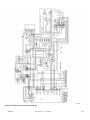
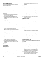
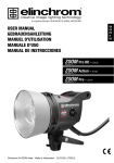
Figure 2-7 PC 324AE Power Converter Internal Wiring
312-3TAEintwrg
FTB 324
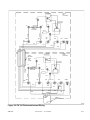
3845112k
Figure 2-8 PC 324 Power Converter Internal Wiring
FTB 324
Revision 8 — 07-17-2002
2-13
T101 TRIGGER
TRANSFORMER
UPPER
RED
FLASHHEAD
P8
T102 COUPLING
TRANSFORMER
P3
P6
P7
FT 101
FLASHTUBE
RC 101
14 RED
14 BLUE
P11
RC102
BLK
BLU
RED
PUR
WHT
SHIELD
RED
P1
BLU
P2
P5
P4
P12
BLK
WHT
PUR
T101 TRIGGER
TRANSFORMER
LOWER
WHITE
FLASHHEAD
CABLE
BETWEEN
UPPER
AND
LOWER
P8
T102 COUPLING
TRANSFORMER
P6
P7
P3
FT 101
FLASHTUBE
14 RED
14 BLUE
RC 101
RC102
BLU
RED
P11
BLK
WHT
PUR
SHIELD
RED
P1
BLU
P2
P4
WHT
RED
BLU
BLK
P5
P12
PUR
BLK
(TAG)
WHT
PUR
CABLE TO
POWER CONVERTER
fh324iw
Figure 2-9 FH 324 Flashhead Internal Wiring
FTB 324
Revision 8 — 07-17-2002
2-14
Section 3 — Maintenance and Troubleshooting
Safety
Read the warning on Page iii. Work safely as follows:
1. Remove all jewelry before opening equipment.
2. Shut off the equipment.
installed in the equipment, should be kept in antistatic bags or containers.
Diagnostic Testing
Basic functional testing procedures follow. The
6. Turn off power and disconnect test equipment.
only effective way to check out interconnected
power converters is to disconnect the wire labeled
master/slave interconnect that is connected to
TB1-4 and check them as single units, as
described in the subsection Checkout Procedures.
Preventive Maintenance
Sync Signal Evaluation
3. Remove component or connect test equipment.
4. Replace the component.
5. Turn on the power and test the system.
Carry out the following inspection and cleaning
procedures at least once a year:
1. Verify that moisture has not entered the
equipment through gaskets or seals, or collected inside as condensation.
2. Verify that all drain holes are clear.
3. Check terminal blocks and relays for evidence
of corrosion and electrical arcing. Clean or
replace any component that shows evidence of
high-voltage damage.
4. Check flashtube connections for signs of pitting or arcing. Verify that anode and cathode
connections are firmly tightened.
5. Check all electrical connections for tightness
and verify the absence of corrosion or electrical arcing.
6. Clean the outside surface of the lens with liquid detergent and water. Wipe it gently with a
soft cloth or paper towel.
7. Clean the inside surface of the lens with an
FTCA-approved professional plastic cleaner.
Wipe the lens with cheesecloth only. Do not
use regular cloth or paper towels. A lens cleaning kit, Part Number 8630801, is available
from FTCA.
The top light must be operated by the master
power converter and the photocell must be connected to the master power converter. In the
event of a top red light failure at night, the master
power converter places a back-up signal on the
line that causes all connected units to flash the
white lights at the correct night intensity.
The sync signal is a pulse and difficult to evaluate
with a meter. Different meters respond differently. You may detect the sync pulse as an instantaneous movement of the meter indicator. A
digital meter with a max-min function may capture part of the pulse. This is generally a sufficient indication of a pulse being present. (A 24V
pulse of 16 ms. width might read 12V on a 100
ms. capture time of max-min function.)
RFI Problems
Storage
Radio frequency interference (RFI) can cause a
No special considerations are required for
long-term storage of any major assembly, such as
the power converter, flashhead, photocell or any
internal component. Circuit boards, when not
FTB 324
Refer to Figure 2-5. Note that, for each power converter, a master/slave interconnect line and its
return line are connected to TB1-4 and TB1-5
respectively. All units place a sync pulse on the
line; the first sync pulse on the line synchronizes
the remaining lights to flash all the lights at the
same time. PCB1 in each power converter generates a sync pulse. The width of the sync pulse controls the mode of operation.
light to flash intermittently, at the wrong rate, or
at the wrong intensity. RFI can enter the light by
any wire to or from the unit. For example:
Revision 8 — 07-17-2002
3-1
· RFI on primary power wires could cause errors
in flash rate and intensity.
· RFI on the master/slave interconnecting wire
could cause a light to switch to and remain in
night intensity.
· RFI on the photocell line could switch a light to
night intensity and force it to remain there.
RFI would not normally cause a light to switch
to day intensity.
· Strong RFI could burn out circuit board components.
While FTCA designed the circuits to reject or
bypass RFI, FTCA cannot guarantee complete
immunity beforehand. After installation, it may
be necessary to add external filters or use other
methods to reduce RFI entering the equipment.
Component Testing
If the capacitor is functional, the needle initially
indicates zero ohms, but soon begins to rise to
higher indicated values. A capacitor that is disconnected from other circuitry is defective if it
does not exhibit this behavior. The length of time
it takes the needle to reach the 1-megohm reading
(about 65% full-scale) is a measure of the capacitance. For example, the time is about 5 seconds
for a 10-mfd. capacitor, or 10 seconds for a 20-mfd.
capacitor, and so forth.
Manually discharge the capacitor before repeating this measurement. This test may not detect a
malfunction that occurs only at high voltage.
A bank of capacitors connected in parallel may be
The following procedures describe how to check
most of the unit's major electrical components.
Always make resistance measurements with the
primary power turned off. Before applying power
for voltage measurements, connect test leads or
circuit jumpers, or disconnect existing circuit connections, with the power turned off and storage
capacitors discharged.
Wiring and Cabling
Wires or cables that move repeatedly will eventually break. Ensure that all cables (the flashhead
cable in particular) are securely fastened at short
intervals to the structure or other supports.
Inspection
Closely inspect the units and check the connections against the installation instructions. Also, a
close inspection may reveal insulation breakdown, an overheated component, corrosion, loose
connections, faulty relays, incorrect hookup, and
so forth.
Power Converter Component Testing
Capacitors
Evaluate the condition of a capacitor with an analog volt-ohmmeter operating in the resistance
mode. The following method assumes an instrument with a X100 resistance scale.
3-2
Place the meter leads across the terminals of an
isolated (no electrical connections to other circuits) and fully discharged capacitor. Observe the
subsequent needle movement.
checked as a single unit. If the test indicates a
short circuit, the individual capacitors have to be
disconnected and checked separately. A shorted
capacitor is indicated if the resistance does not
rise above zero after several seconds of measurement.
Burst Choke (L1)
The measured resistance of this choke should be
approximately seven ohms.
Relays
A malfunctioning relay may have faulty contacts,
a sticky mechanism, a bad ground, or a defective
coil. You may determine the first two possibilities
by inspection and manually exercising the armature. You can confirm a defective coil by measuring the resistance. To measure the resistance of
relay coils, first remove the wires from one of the
connections to the coil terminals on the relay.
Mode Relay (K2): 24 VDC; 290 ohm coil
Discharge Relay (K3): 120 VAC; 290 ohm coil
Timing and Trigger Board (PCB1)
Replace this board with one known to be in good
condition. Note that the PCB1 board part numbers in this manual are either 24740xx or
24747xx. Call Customer Service for technical
assistance at 1-800-821-5825.
PCB1 part numbers vary. Be certain that you have
the complete number available, which is
imprinted and written on your board.
Revision 8 — 07-17-2002
FTB 324
HV Rectifier Board (PCB2)
Replace this board with one known to be in good
condition.
Alarm Relay Board (PCB5) (PC 324)
Replace this circuit board with one known to be in
good condition.
Sense Module (PCB4)
Replace this circuit board with one known to be in
good condition.
Flashtube (FT101)
Visually inspect the flashtube for broken electrodes, cracked glass, and the solder connections
of the pins. A darkened envelope does not necessarily mean the light output would be unacceptable. Before concluding that a faulty flashtube is
responsible for an inadequate flash, first rule out
other possible causes such as weak or absent discharge voltage or triggering pulses.
Trigger Transformer (T101)
The resistance of the secondary winding (potted
assembly) should be approximately 160 ohms.
Check the upper and lower ferrite core pieces for
cracks. Check the mounting screws for tightness.
Discharge Resistor (R1)
The measured resistance of this component
should be 35,000 ohms.
Burst Resistor (R2)
The measured resistance of this component
should be 250 ohms (two 500-ohm resistors in parallel)
Power Transformer (T1)
To test this transformer, first remove PCB1 and
PCB2. Apply power to the unit and measure secondary winding voltages at the terminals indicated in Table 3-1.
Table 3-1 T1 Transformer Voltages
Terminals
Voltage Range
TB3-1 to TB3-9
900-1050 volts AC*
PCB1 J5-8 to chassis
100-120 volts DC
PCB1 J3-1 to J3-2
22-26 volts AC
* If this AC voltage is substantially below the specified
minimum value, check tuning capacitor C4.
Trigger Coupling Transformer (T102)
The coupling transformer should not have open
windings. An ohmmeter will indicate a shorted
winding because of wire size. Check with an ohmmeter at the wire terminals. Check upper and
lower ferrite core pieces for cracks.
Photocell Testing
The photocell is wired directly to the master
power converter at TB1-1 and TB1-2.
1. Disconnect the photocell. The system should
go to nighttime operation in about 45 seconds.
2. Disconnect the master/slave interconnect line
on each power converter.
3. Operate the intensity control switch on each
power converter in turn.
4. If each power converter operates correctly
Trigger Coupling Transformer (T3)
The coupling transformer should not have open
windings. An ohmmeter will indicate a shorted
winding because of wire size. Check with an ohmmeter at the wire terminals. Check upper and
lower ferrite core pieces for cracks.
Red Light Module Components
Marker Relay (K5): 24 VDC; 470 ohm coil. Replace
the entire Red Light Module to replace the relay.
Marker Sense Transformer (T1 on PCB3): The
Marker Sense Transformer is mounted on PCB3.
If you suspect the transformer, replace the entire
Red Light Module.
Flashhead Component Testing
The following subsections describe component
testing for the components in the flashhead.
FTB 324
with the intensity control switch, the problem
is the photocell, or its wiring, or troubleshoot
the circuits in the erroneously operating
power converter.
5. Reconnect all wires.
With the Intensity Select Switch in AUTO during
daylight, completely block light from entering the
photocell. If the system does not enter night mode
after a few minutes, replace the photocell. At
night, shine a light on the photocell, if the system
does not enter day mode after a few minutes,
replace the photocell.
Component Removal and
Replacement
Component location diagrams are provided in Fig-
ure 4-1, through Figure 4-3 in Section 4 — RecomRevision 8 — 07-17-2002
3-3
mended Spare and Replaceable Parts. Internal
electrical wiring diagrams are provided in Section
2 and on the Information Card that is fastened
inside the power converter cover.
1. Reverse the removal procedure.
2. Verify that wiring agrees with the wiring diagram on the Information Card. Wires must be
replaced exactly as removed. In some
Note the location and color of all wires that you
instances, a quick-connect wire terminal does
disconnect. When you replace the wiring after you
replace the components, ensure that the wiring
conforms exactly to the wiring diagrams.
not seat properly if it is not placed on the terminal cluster exactly as it was before removal.
The general procedure for removing components
lation on the wire terminal and the insulation
is a logical one and is as follows:
1. Obtain access to the component in question:
a. Disconnect completely or partially the
wiring to components first that prevent clear access.
This occurs by interference between the insusurrounding their terminal cluster on the
capacitor. FTCA recommends that you lightly
squeeze the quick-connect wire terminals with
pliers before reinstalling them over the capacitor terminal blades.
Input Power Module
Removal
b. Completely remove or relocate these
1. Remove all accessible wires and cable connec-
components.
3. Disconnect the wiring to the component
that you want to replace.
4. Remove this component.
5. Replace everything in the reverse order:
first the component, then the wiring, then
the components that allowed you access. In
some cases, you may have to place some
wires on the component before you fasten it
in place, then replace the remaining wires.
Most components are relatively easy to access for
removal. Only those that are more difficult are
described.
tors attached to the Input Power Module and
to T1 located under the Input Power Module.
2. Loosen the truss-head screws in the base that
fasten the Input Power Module to the base.
3. Remove the screw under the ground terminal
to the left of TB4. This screw fastens the Input
Power Module bracket to the Component
Bracket.
4. Carefully slide the Input Power Module
bracket to the right and lift it out. Ensure that
connectors are not bent while doing so.
5. Remove any additional connections that you
must to remove the Input Power Module
Power Converter
bracket.
Capacitors
Before removing or replacing a capacitor always
ensure it is discharged by checking with a voltmeter directly across the terminals. Discharge a
capacitor by placing a resistance (25 watts/10,000
ohms or greater) between its terminals. Direct
shorting may damage the capacitor, and connecting the terminals to the equipment chassis may
fail to discharge it.
Remove the fuse for this procedure to prevent
accidental application of power if the interlock
switch is inadvertently depressed.
Removal
Replacement
1. Replace the Input Power Module in the
reverse sequence to that of Removal.
2. Verify that wiring matches the Information
Card and restore the wire routing to its original state.
K2 Mode Relay
You must first remove the Red Light Module and
PCB1 as in Section Red Light Module, Section
Timing and Trigger Board (PCB1), and the Component Bracket for adequate access to the K2
Mode Relay.
Removal
1. Disconnect the wires leading to capacitors.
1. Remove the Red Light Module.
2. Remove the hold-down screws.
3. Lift the capacitors from their receiving holes.
2. Remove PCB1.
Replacement
3-4
Revision 8 — 07-17-2002
FTB 324
3. Loosen the four truss-head screws in the base
that fasten the bracket to the base.
4. Loosen the screw that fastens the bracket to
the Input Power Module.
5. Slide the bracket up off the screws. Be careful
of the cable and cable connectors. You may
hang the bracket over the edge of the connector panel to perform the remaining steps.
6. Carefully disconnect the wires from the terminals of the component and note their locations
so that you may more easily replace them.
7. Remove the screws that hold the K2 relay to
the base.
Replacement
Reverse the removal procedure.
PCB2 HV Rectifier Board
The HV rectifier board is mounted on the right of
the Component Bracket between the Component
Bracket and the Red Light Module. You access it
by first removing the Red Light Module and then
the Component Bracket. Use the following procedure:
Removal
1. Remove the Red Light Module.
2. If you have a right-angle Phillips-head screwdriver available, it is not necessary to remove
8. Remove the K2 relay.
the Component Bracket before doing Step 3.
Replacement
1. Replace the K2 relay in the reverse sequence
of that of removal.
2. Verify that wiring matches the Information
Card and restore the wire routing to its original state.
Otherwise, remove the Component Bracket.
3. Loosen, but do not remove, the screws holding
the HV rectifier board to the terminal block
TB3. Slide the circuit board out from under
the terminal block screws.
Replacement
K3 Discharge Relay
1. Slide the circuit board under the terminal
Removal and replacement are similar to those in
Section K2 Mode Relay.
2. Replace the Red Light Module.
K5 Marker Control Relay
To replace K5, replace the entire Red Light Module.
block screws and tighten them.
3. Verify that wiring matches the Information
Card and restore the wire routing to its original state.
PCB4 Sense Module
L1 Burst Choke
Removal and replacement are similar to those in
Section K2 Mode Relay.
Removal and replacement are similar to those in
Section K2 Mode Relay.
PCB1 Timing and Trigger Board
Red Light Module
PCB1 is mounted on the left side of the power converter as you face the wall-mounted power converter.
Removal
1. Remove all connector plugs from PCB1 headers, and:
· On J12 Pins 1 & 2 remove the wht/blu and
blu wires (if present).
· On J14 Pins 1 & 2 remove the brn and grn
wires (if present).
Removal
1. Remove the external wires connected to TB5.
2. Unplug all harness connections to the Red
Light Module.
3. Loosen two screws in the base that fasten the
Red Light Module to the base.
4. Remove the Red Light Module. Be careful of
components and connectors.
5. Disconnect the ground wire from the back of
the module.
Replacement
· On J15 Pins 1 & 2 remove the yel and
1. Replace the Red Light Module in the reverse
wht/yel wires.
2. Loosen (but do not remove) the four screws
sequence to that of Removal.
2. Verify that wiring matches the Information
located near the corners of the board.
Card and restore the wire routing to its origi-
3. Slide the board so that it clears the four
screws and remove it from the power con-
nal state.
verter.
FTB 324
Revision 8 — 07-17-2002
3-5
R2A and R2B Burst Resistors
Removal and replacement are similar to those in
Section K2 Mode Relay.
Replacement
1. Align the pins on the flashtube base with the
clamps of the terminal screw lugs, making
T1 Power Transformer
Removal
sure that the red dot on the flashtube base
1. Remove the Input Power Module.
2. Remove the four screws holding the trans-
coincides with the red wire on the support col-
former to the base plate and remove the transformer.
umn directly under it.
2. Insert the flashtube and settle it into place,
making sure the ceramic base is resting
Replacement
1. Replace the power transformer in the reverse
sequence to that of Removal.
2. Verify that wiring matches the Information
Card and restore the wire routing to its original state.
directly on the tops of the screw lugs.
3. Ensure that the tube is vertical.
4. Tighten the three screws on the screw lugs to
secure the flashtube.
White Lens Section:
Removal
T3 Trigger Coupling Transformer
1. Loosen the two screws securing the upper
flashtube assembly and lift the plate up and
Removal
1. Remove the Red Light Module.
out of the way to allow access to the bottom
2. Remove PCB1.
3. Loosen the four screws that hold the Component Bracket to the base.
flashtube.
2. Pull out the flashtube in the white lens bottom
section. You may have to rock it back and
4. Slide the Component Bracket up off the
screws. Be careful of the cable and cable connectors. You may hang the Component
Bracket over the edge of the connector panel to
perform the remaining steps.
5. Pay special attention to the orientation of the
wires on the transformer and their connec-
tions. Replace them in the same orientation.
Replacement
1. Replace T3 in the reverse sequence to that of
Removal. Note the connections to T3 as in
Step 5 of the Removal, and replace the wires
forth slightly to remove the tube.
Replacement
1. Align the pins on the flashtube base with their
sockets. Notice that the spacing of the flashtube pins must match that of its sockets.
2. Insert the flashtube and settle it into place,
making sure the ceramic base is resting
directly on the tops of the pin sockets.
3. Ensure that the tube is vertical.
4. Close the top red lens section and secure the
latches.
to their connections in the same way.
Trigger Transformer, T101
Card and restore the wire routing to its origi-
Refer to Figure 4-2 FH 324 Flashhead Component
Location.
2. Verify that wiring matches the Information
nal state.
Removal
1. At the trigger wire post adjacent to the flash-
Flashhead
tube, remove the large diameter wire coming
FT101 Flashtube:
Red Lens Section:
from the trigger transformer.
2. At one of the smaller, side-mounted ceramic
Removal
1. Unlatch the two latches and lift the red lens to
allow access to the three screws holding the
flashtube pins.
2. Using a #2 Phillips-blade screwdriver, loosen
the three screws (on screw lugs) directly under
the flashtube, which hold the flashtube con3-6
nector pins. This enables you to remove the
flashtube.
posts, remove the small wire to the trigger
transformer. Do not disconnect the primary
winding wires (seven turns of hook-up wire).
3. Remove the two 4-40 x 2" Phillips®-head
screws holding the transformer assembly to
the bracket. Note the orientation of the
Revision 8 — 07-17-2002
FTB 324
molded secondary winding with respect to
fixed features on the bracket, since it must be
reinstalled with this same orientation.
4. Remove the outer half of the core and lift off
the molded secondary winding. The primary
winding will remain hanging in place.
5. Remove the inner half of the core.
Replacement
1. Reassemble the primary and secondary wind-
ings over the two halves of the core. Attach the
core to the bracket using the two long screws.
2. Reattach the wires. Verify that wiring is in
accordance with Figure 2-8 FH 324 Flashhead
Internal Wiring.
Coupling Transformer, T102
Refer to the flashhead component locations dia-
gram Figure 4-2 and internal wiring diagram Figure 2-8.
Removal and replacement are similar to the pro-
marker alarm but does not cause back-up whitenight operation.
Each power converter may control and monitor a
tier of steady burning marker lights. In some
installations there may be a power converter that
does not have associated marker lights.
Marker Light Programming
The 2-4740-XX timing board(PCB1) has jumpers/switches labelled MKR0 and MKR1 which are
cut/opened for programming the number of markers installed on a tier.
The 2-4747-XX timing has software programming
for selecting the monitoring of marker lights. The
XX in the 2-4747-XX part number label shows the
software program number. The program is set at
the factory.
cedure for the trigger transformer (T101).
Testing Each Unit
Operational Checkout
To test each unit in a triple-unit system, use the
following procedures:
Single-Unit System
During testing expose the photocell to normal out-
1. Disconnect the wires labeled master/slave
interconnect at TB1-4 and TB1-5.
door daylight. Carefully perform the following
steps and take the suggested action if any of the
responses differ from the response described.
2. Test this unit as described in Section Sin-
Triple-Unit System
Photocell Testing
A system with three power converter units is a
The photocell is wired directly to the first (master)
triple-unit system. Refer to Section 2 that shows
triple-unit installation. You connect the top unit;
designated the master unit, terminals TB1-1 and
TB1-2 directly to the photocell. The two other
power converters each jumper together their terminals TB1-1 and TB1-2.
Each power converter sends a synchronization
signal over the , master/slave, bidirectional wires
at terminals TB1-4 and TB1-5 to flash all lights
together. The top power converter places a signal
on the master/slave wires to force the system to
flash in white mode(white night backup) if the top
red lamp fails to flash. A lamp going out in a tier
of red incandescent marker lights indicates a
FTB 324
gle-Unit System.
power converter at TB1-1 and TB1-2.
1. First, disconnect the photocell. The singleunit, or triple-unit, system should revert to
nighttime operation in about 45 seconds.
2. Disconnect TB1-4 and TB1-5 on each power
converter.
3. Operate the intensity control switch on each
power converter in turn.
4. If each power converter operates correctly
with the intensity control switch, troubleshoot
the photocell wiring or the circuits in the
incorrectly operating power converter.
5. Reconnect all wires.
Revision 8 — 07-17-2002
3-7
Checkout Procedures
Use Table 3-3 to checkout the equipment. Open
the cover of the power converter or converters to
perform the procedures. To check out multiple
units, all units must be operating. Observe and
confirm the operation for each power converter
individually. The procedures assume the photocell
sity select switches to AUTO, which allows the
photocell to control the intensity.
The steps in Table 3-2 or Table 3-3 are related
to each other and should be performed together in
the sequence given here. If a unit does not behave
exactly as described, proceed to Troubleshooting
the System in this section.
is exposed to daytime sky conditions. Set all inten-
Table 3-2 Checkout of Power Converters with PCB1 24740xx Board
Setup to Check Normal Daytime Operation
Photocell in daylight.
1) Intensity Select Switch in
AUTO.
2) Apply power (pull out interlock
switch plunger).
Setup to Check Normal Nighttime Operation
Place opaque cover over photocell (block all light).
1) Intensity Select Switch in
AUTO.
2) Apply power (pull out interlock
switch plunger).
Setup to Check
Default Night Operation
Perform this procedure for each
power converter individually in a
multi-unit system.
1) Place opaque cover over photocell (block all light).
2) Intensity Select Switch in
AUTO.
3) Remove power.
4) Disconnect purple wire on
TB2-6. This fails the red flashing light.
5) Reapply power.
3-8
Response — LEDs and Structure Lights
· HV Warning Light is ON
· DAY LED (I 11) is on. On during daylight.
· NITE ERR LED (I 1) is off.
· NITE LED (I 6) is off. Off during daylight.
· DAY ERR LED (I 7) is off.
· MKRS LED (I 12) is off during daylight.
· PEC ALM (I 2) is off.
· NEON bulb (I 13) is on; trigger voltage is
· WHT ALM LED (I 8) is off.
available; this bulb may blink.
· RED ALM LED (I 3) is off.
· White strobe is flashing at daylight high
· MKR ALM LED (I 9) is off.
intensity.
· FAN LED (I 4) not used.
· Red markers are off.
· SYNC LED (I 10) flashes on in a regular
pattern. May be difficult to see.
· CONF LED (I 5) “flashes” on after each
strobe flash. May be difficult to see.
Response — LEDs and Structure Lights
· HV Warning Light is ON
· DAY LED (I 11) is off. Off at night.
· NITE ERR LED (I 1) is off.
· NITE LED (I 6) is on. On at night.
· DAY ERR LED (I 7) is off.
· MKRS LED (I 12) is on at night if markers
· PEC ALM (I 2) is off.
are associated with the power converter
· WHT ALM LED (I 8) is off.
being observed.
· RED ALM LED (I 3) is off.
· NEON bulb (I 13) is on; trigger voltage is
· MKR ALM LED (I 9) is off.
available; this bulb may blink.
· FAN LED (I 4) not used.
· Red strobe is flashing at night intensity.
· SYNC LED (I 10) flashes on in a regular · Associated red markers are on.
pattern. May be difficult to see.
· CONF LED (I 5) “flashes” on after each
strobe flash. May be difficult to see.
Response — LEDs and Structure Lights
Responses after three flash cycles:
· DAY LED (I 11) is off. Off at night.
· HV Warning Light is ON
· NITE LED (I 6) is on. On at night.
· NITE ERR LED (I 1) is off.
· MKRS LED (I 12) is off at night during white
· DAY ERR LED (I 7) is off.
back-up operation.
· PEC ALM (I 2) is off.
· NEON bulb (I 13) is on; trigger voltage is
· WHT ALM LED (I 8) is on.
available; this bulb may blink.
· RED ALM LED (I 3) is on.
· White strobe is flashing at white back-up
· MKR ALM LED (I 9) is off. Goes on initially intensity.
but then goes off when structure enters · Associated red markers are off.
white night back-up mode.
Remove power.
· FAN LED (I 4) not used.
Restore all wires to their previous positions
· SYNC LED (I 10) flashes on in a regular before disconnecting any new wires.
pattern. May be difficult to see.
Reconnect the purple wire on TB2-6.
· CONF LED (I 5) “flashes” on after each Reapply power.
strobe flash. May be difficult to see.
Revision 8 — 07-17-2002
FTB 324
Table 3-2 Checkout of Power Converters with PCB1 24740xx Board (Continued)
Setup to Check
Marker Alarm
1) Place opaque cover over photocell (block all light).
2) Intensity Select Switch in
AUTO.
3) Remove power.
4) Remove fuse F4.(removes
power to marker lights).
5) Apply power.
Setup to Check White Alarm
for Day Operation
1) Remove opaque cover over
photocell.
2) Intensity Select Switch in
AUTO.
3) Remove power.
4) Disconnect black wire from
TB2-4.
5) Reapply power.
Setup to Check Red Alarm for
Night Operation
1) Place opaque cover over photocell (block all light).
2) Intensity Select Switch in
AUTO.
3) Remove power.
4) Disconnect purple wire from
TB2-6.
5) Apply power.
FTB 324
Response — LEDs and Structure Lights
Responses are the same as those for normal · Red light is flashing at night intensity.
nighttime (previous) except for the following: · Red markers are off.
· MKR ALM LED (I 9) is on.
Remove opaque cover over photocell. Remove
· MKRS LED (I 12) is on.
power.
Replace fuse F4.
Reapply power.
Response — LEDs and Structure Lights
Responses are the same as those for daylight · CONF LED (I 5) is off.
(previous) except for the following:
· White strobe is off.
· DAY ERR LED (I 7) is on.
Remove power.
· WHT ALM LED (I 8) is on. Turns on in three Replace wire on TB2-4.
flash cycles after applying power.
Reapply power.
Response — LEDs and Structure Lights
Responses are the same as those for normal · CONF LED (I 5) is off.
nighttime (previous) except for the following: If you leave the system on, it will next attempt to
· NITE LED (I 6) is on.
flash in white night backup (default).
· WHT ALM LED (I 8) is off.
Remove power.
· RED ALM LED (I 3) is on. Turns on in three Replace wire on TB2-4.
flash cycles after applying power.
Reapply power.
Revision 8 — 07-17-2002
3-9
Table 3-3 Checkout of Power Converters with PCB1 24747xx Board
Setup: Check Normal Daytime
Operation
1) Apply power (pull out the interlock
switch plungers to the service
position).
2) Set the intensity select switch or
switches to AUTO.
3) Verify that the responses occur at
each power converter in the system.
Setup: Check Normal Nighttime
Operation
1) Place an opaque (blocks all light)
cover over the photocell. Several
seconds may pass before the
photocell responds to the darkened condition after power is
applied.
2) Set the intensity select switch or
switches to AUTO.
3) Apply power (pull out the interlock
switch plungers to the service
position).
Setup: Check Normal Default
Night Operation
Perform the following procedure for
its power converter in a multiple-unit
system.
1) Cover the photocell with an
opaque (blocks all light) cover.
2) Set the intensity select switch or
switches to AUTO.
3) Remove power.
4) Disconnect the purple wire on
TB2-6. This fails the red flashhead.
5) Reapply power.
3-10
Response — LEDs and Structure Lights
Verify that the following responses occur at each · The DAY LED (I 5) is on. It is on durpower converter in the system:
ing daylight.
· The HV Warning Light is on.
· The NITE LED (I 10) is off for day· The NITE ERR LED (I 15) is off.
light operation.
· The DAY ERR (I 9) is off.
· The MKRS (markers) LED (I 4) is off
· The PEC ALM (I 14) is off.
during daylight operation.
· The WHT ALM LED (I 8) is off.
· The clear NEON bulb (I 3) is on indi· The RED ALM LED (I 13) is off.
cating the presence of trigger voltage
· The MKR ALM LED (I 7) is off.
for the flash tube. This bulb may
· The FAN LED (I 12) is off.
blink.
· The SYNC LED (I 6) “flicks” on regularly. May · The white light is flashing at the daybe difficult to see in bright daylight.
time high-intensity for this unit.
· The CONF (confirm) LED (I 11) “flashes” on · The associated red incandescent
after each strobe flash. May be difficult to see markers are off.
in bright daylight.
Response — LEDs and Structure Lights
Verify that the responses occur as in Daytime · The MKRS (markers) LED (I 4) is on
(previous) except for those in the following list: if markers are associated with the
· The DAY LED (I 5) is off.
power converter being observed.
· The NITE LED (I 10) is on for night operation. · The red light is flashing at the nighttime intensity for this unit.
· The associated red incandescent
markers are on.
Response — LEDs and Structure Lights
Verify that the following responses occur as com- · The system is flashing in white night
pared to those in Check Normal Daytime Opera- back-up intensity.
tion, except for those in the following list (after Remove power.
three flash cycles):
Reconnect the purple wire on TB2-6.
· The WHT ALM LED (I 8) is on.
Restore all wires to their previous con· The RED ALM LED (I 13) is on.
nections before disconnecting any new
· The DAY LED (I 5) is off.
wires.
· The NITE LED (I 10) is on for night operation. Reapply power.
· The MKRS (markers) LED (I 4) is off. It is off
during white night backup mode.
Revision 8 — 07-17-2002
FTB 324
Table 3-3 Checkout of Power Converters with PCB1 24747xx Board (Continued)
Setup: Check Marker Alarm
Operation
1) Cover the photocell with an
opaque (blocks all light) cover.
2) Set the intensity select switch or
switches to AUTO.
3) Remove power.
4) Remove fuse F4.
5) Reapply power.
Response — LEDs and Structure Lights
Verify that the following responses occur as com- · Replace F4 and recycle the unit with
pared to those in Check Normal Daytime Opera- the Intensity Select Switch as done in
tion, except for those in the following list (after Setup
three flash cycles):
· Reapply power.
· The DAY LED (I 5) is off.
· The unit should now be operating
· The NITE MODE LED (I 10) is on.
normally in night mode; that is: red
· The MKRS (I 4) LED is on indicating that light flashing, markers turned on, and
markers should be on.
no alarm.
· The MKR ALM (I 7) LED is on indicating a Remove the temporary opaque cover
marker alarm.
placed over the photocell in Step 2.
· The top flashhead (red) is flashing.
Set Intensity Select Switch to AUTO.
· Remove power.
Replace Fuse F4.
Setup: Check White Alarm for
Daytime Operation
1) Remove the opaque cover from
the photocell.
2) Set the intensity select switch or
switches to AUTO.
3) Remove power.
4) Disconnect the black wire from
TB2-4. This fails the white flashhead.
5) Reapply power.
Response — LEDs and Structure Lights
The following responses indicate a failure to flash · The DAY ERR LED (I 7) is on.
in day mode. Verify that they occur as compared · The SYNC LED (I 6) flicks on reguto those in Check Normal Daytime Operation, larly.
except for those in the following list (after three · The CONF (flash confirm) LED
flash cycles):
(I 11) is off.
· The WHT ALM LED (I 8) is on. (The power Remove power.
converter executes 3 flash cycles internally Reconnect the black wire to TB2-4.
after power application. The White Alarm Reapply power.
turns on at the end of the three cycles.) Verify operation as in Daytime Operation.
Setup: Check Red Alarm for
Night Operation
1) Place the opaque cover over the
photocell.
2) Set the intensity select switch or
switches to AUTO.
3) Remove power.
4) Disconnect the purple wire from
TB2-6.
5) Reapply power.
Response — LEDs and Structure Lights
The following responses denote a light failure dur- · The CONF (flash confirm) LED
ing normal nighttime operation. Verify that they (I 11) is off.
occur as compared to those in Check Normal These denote a light failure during norDaytime Operation, except for those in the follow- mal nighttime operation.
ing list (after three flash cycles):
NOTE: If you leave the system on, it will
· The DAY MODE LED (I 5) is off.
next attempt to flash in white night
· The NITE MODE LED (I 10) is on.
backup mode(default).
· The RED ALM LED (I 13) is on. (The power Remove power.
converter cycles executes 3 internal flash Reconnect the purple wire to TB2-6.
cycles before turning on the Red Alarm.) Reapply power.
· The SYNC LED (I 6) flicks on regularly. Remove cover from photocell.
Verify operation as in Daytime Operation.
Reapply power.
Troubleshooting the System
Effective troubleshooting begins with careful
observations of operating behavior, often leading
directly to the cause of a problem. Diagnostic procedures in this subsection are divided into two
categories: unit level, originating in a single unit;
and system level, problems affecting all units in a
triple-unit system in the same way. However, in a
triple-unit system some unit-level malfunctions
could cause problems involving the entire system.
FTB 324
For example, if one light in a triple-unit system
fails to flash, Table 3-4 directs you to Table 3-5,
the troubleshooting guide for a unit-level problem
(but not a system-level problem).
For each symptom, the troubleshooting guides list
one or more probable causes in descending order
of probability. Continuing with our example,
assume that the light fails to flash during the day
(No in column 1) and at night (No in column 2).
High voltage is absent (No in column 3), but low
voltage is present (OK in column 4). This condition is described in the fourth row of Table 3-5.
Revision 8 — 07-17-2002
3-11
The last column lists possible causes. The most
probable cause is a shorted capacitor, the second
most probable cause is a shorted flashhead cable,
and so on.
When you trace a problem to a specific component, see Subsection Power Converter Component
Testing and Subsection Component Removal and
Replacement, in this Section.
Table 3-4 Selecting the Correct Troubleshooting Guide
Triple-Unit System
Single-Light
Units Affected Differently, Usually Only One
Failing Unit (Unit-Level Problem)
System
Troubleshooting
Guide
Table 3-5
All Units Affected the Same Way
(System Level Problem)
Table 3-5
Table 3-6
Table 3-5 Unit Troubleshooting Guide
Flash Conditions
Other Conditions
†
LV*
†
OK
Day
Night
No
No
No
No
No
No
No
No
No
No
No
No
No
OK
No
No
OK
No
No indicators
lit on PCB1
OK
High
Intensity
OK
OK
Red Alarm
OK
OK
OK
OK
All Markers Out
OK
Backup
Intensity
OK
OK
OK
OK
OK
OK
Marker Alarm
-
-
OK
OK
Incorrect Mode
OK
No
OK
OK
Red Alarm
OK
Backup
Intensity
OK
OK
OK
Red Alarm
OK
OK
OK
OK
OK
White Alarm
OK
OK
OK
White Alarm
HV
OK
Probable Causes (All Units Unless Specifically Indicated)
· Flashhead cable connec- · T3 Transformer
tions
· BR1 Bridge
· T1 Transformer
· PCB1
· Varistor MOV
· T1 Transformer
· F1 Fuse
· T1 Transformer
· S1 Interlock
· Connections - main power
· C2A-D, or C3 shorted · Shorted FH Cable
· PCB1 Board
· BR1 Bridge
· T1 Power Transformer
· PCB1 Board
· K2 Relay
· Photocell Circuit
· Intensity select switch setting
· F4 Fuse
· PCB1 Board
· K5 Marker Control Relay ‡
‡
· K5 Marker Control Relay · PCB1 Board
Blows Fuse F1
Markers Stay On
Red
Red or
White
No
· K2 Relay
· One or more marker lamps
out or incorrect wattage
· K5 Marker Control Relay
· PCB1 Board
· PCB3
‡
· S2 Intensity Select Switch
· PCB1
is not in AUTO position
· Flashtube (top red flash- · PCB1
head)
· K2 Relay
· C3 Capacitor Open
· L1 Burst Choke
· K5 Relay
· R2 Burst Resistor
· F5
· PCB1 Board
† HV = High voltage. PCB2 or HV neon lamp lit confirms HV.
‡ Replace the entire red light module if any components therein fail.
* LV = Low voltage. Any PCB1 LEDs on confirms LV.
3-12
· PCB1 Board
· PCB1 Board
· Flashtube (bottom flashhead)
· PCB1 Board
· K2 Relay
Revision 8 — 07-17-2002
· L2 Flash Choke
· C2A-D Capacitors Open
· K5 Relay
FTB 324
Table 3-6 System Troubleshooting Guide
Flash Conditions
Other Conditions
Probable Causes
Day
Night
OK
Day Flash
Possible photocell Error
Red
OK
Possible photocell Error
-
-
Units mixed red and white
· Photocell
· Jumper on TB1 & 2 on
slave units missing
· PCB1 Board
· Intensity Select Switch
· Photocell
· Intensity Select Switch
· Photocell cable connected to TB1-1
and -3 (all units will be in night mode)
OK
OK
Units not flashing together
· Master/slave interconnect cable connected to TB1-4 and TB1-5.
No
No
No lights
· PCB1 in one unit.
· Main power line
Using the Intensity Select Switches —
Finding the Failing Unit at Night
For normal operation, set the intensity select
switches on each unit to AUTO. In AUTO, an
intensity signal through the master/slave interconnect wires on TB1-4 and TB1-5 controls the
day or night intensity level of all power converters
and associated lights. Any power converter may
send the sync signal on these wires, which flashes
all lights at the same time. Normally, all units on
a structure have backup enabled. Should a flashhead fail in AUTO night operation, the power converter with the failing flashhead sends a back-up
signal to the other units on the interconnect
wires. If the failing flashhead is the top-most and
is correctly connected to the master, all strobes
will go into white back-up mode.
You can switch any unit to day or night operation
(manual operation) with its intensity select
switch. In manual operation, the following conditions occur on the switched power converter:
FTB 324
· Intensity Select Switch
In Night Mode:
· It does not send a back-up signal.
· It operates the red light only.
· It clears its red alarm (if it has one) and then
re-establishes the alarm.
· It does not affect the other units.
In Day Mode:
· It ignores the master/slave interconnect line
(sync and back-up signals).
· It operates the white light only.
When a top red light alarm occurs at night, the
back-up signal from the failing master power converter switches all units to night intensity white
operation. With the preceding information, you
can determine master unit in the system is causing the entire system to run in white night intensity.
Revision 7 — 06-05-2002
3-13
This page is intentionally blank.
3-14
Revision 7 — 06-05-2002
FTB 324
Section 4 — Recommended Spare and Replaceable Parts
Power Converter Parts
Repackaging
Table 4-1 lists the major replaceable parts.
Equipment must be returned in a container that
provides maximum protection during shipping
and handling. If the original cartons and packaging material are no longer available, package the
power converter and flashhead separately as in
the following subsections.
Flashhead Parts
Table 4-2 lists the major replaceable parts.
Photocell Parts
Power Converter
The part number for the PEC 510 Photocell is PN
#1855001.
Package and ship the power converter in an
upright position; that is, with the feet downward.
Pad the power converter so that the feet cannot
penetrate the box during shipment. Box each
power converter separately using a double thickness cardboard container and adequate padding.
Do not drop. Use appropriate warning labels on
the outside of the container.
Flashhead
Package and ship the flashhead in an upright
position. Box each flashhead separately and use
adequate padding. Attach the flashhead base to a
plate measuring 19 inches square (e.g., 3/8 inch
plywood). Use a double thickness cardboard (or
wood) container which is 19 inches square by
about 32 inches high (inside dimensions). Use soft
packing or a cardboard collar around the lens to
prevent tipping inside the container. Do not drop.
Use appropriate warning labels on the outside of
the container.
FTB 324
Revision 8 — 07-17-2002
4-1
Table 4-1 Power Converter Major Replaceable Parts
Item
Description
Part Number
BR1
Diode Bridge
6902806
C2A, C, D
Capacitor, 70 mfd.
6720401
C2B
Capacitor, 40 mfd.
6386503
C3
Capacitor, 1 mfd.
6848202
C4
Capacitor, 3 mfd.
6577903
F1, F2
Fuse, Power, MDL8
F4
Fuse, Marker, MDL5
4901931
4900345
F5, F6
Fuse, MDL1
4900337
HV
Neon, High Voltage Light
4902317
K2
24V Relay, Mode
†
K3
120V Relay, Discharge
†
L1
Choke, Burst
8900493
4850601
L2
Choke, Flash
4175200
LS1
Phone Line Surge Protector
*†
8900494
2865301
†
M1
Red Light Module
MOV
Varistor
PCB1
Timing and Trigger Board — PC 324 (non-“E” models)
*†
PCB1
Timing and Trigger Board — PC 324E — Two Markers
*†
PCB1
Timing and Trigger Board — PC 324E — Three Markers
*†
PCB2
HV Rectifier Board
*†
PCB4
Sense Module
2458005
2811101
PCB5
Alarm Board — “AE” models
2805404
Resistor, Discharge, 35K 50W
6900541
R1
R2A & B
S1
Resistor, Burst (two 500-ohm resistors of the indicated part number comprise one burst resistor)
Switch, Interlock
1811502
6901079
2474019
2474719
2474749
6900532
4901220
†
S2
Switch, Toggle
T1
Transformer, Power, 60 Hz
8799201
8841201
T1
Transformer, Power, 50 Hz
8842901
T3
Transformer, Coupling
8336701
TB1
Terminal Strip, 18 position
4901930
TB2, TB7
Terminal Strip, 6 position
4902257
TB3
Terminal Strip, 11 position
8721011
TB4, TB5
Terminal Strip, 3 position
4902134
TB5
Terminal Strip, 6 position
4902257
TB6, TB8
Terminal Strip, 3 position
4902157
VR1
Varistor, 130V
8250801
VR1
Varistor, 250V
8250802
*
†
4-2
This part number varies according to the specific equipment configuration and function. Be prepared to describe the system
configuration when you call Customer Service for the correct PCB1 Timing and Trigger Board or fuse part number for your
particular system. Have available the part number of your current PCB1 when you call.
Recommended as a spare part.
Revision 8 — 07-17-2002
FTB 324
F5
J1
C2D
C3
C2A
HV
F
1
J2
41
1
TB2
J3
TB5
1
1
C2B
C2C
PCB5
6
EQGND
PCB2
PCB1
SW2
J4
SW1
6
1
INTENSITY
SELECT
8A
F1
J5
TB6
1
J6 1
TB1
1
18
TB4
EQ
1
GND
2
L1 N L2
J7 1
TB3
3
123
G4
LS1
INPUT
POWER
LABEL
BR1
C4
G3
L2
LOOSEN SCREWS
(4 PLACES) TO REMOVE
COMPONENT BRACKET
PCB4
PCB3
E2
G5
L1
R1
T3
K5
E1
SHOWING ITEMS
K2
K3
G6
T1
E3
R2
BELOW COMPONENT
BRACKET
LOOSEN SCREW
TO REMOVE
E4
COMPONENT BRACKET
3-8451-37
REV A
312-3TAECL
Figure 4-1 PC 324 Power Converter Component Location
FTB 324
Revision 8 — 07-17-2002
4-3
Table 4-2 Flashhead Major Replaceable Parts
Item
Description
FT101
Flashtube, Upper Flashhead
8384308
FT101
Flashtube, Lower Flashhead
8384308
Ceramic spacer, 3/4" diameter
5900844
P3, P11
Ceramic spacer, 1/2" diameter, short
5900842
P6, P7, P8
Ceramic spacer, 1/2" diameter, tall
5900843
RC101
Resistor-capacitor network
1403411
RC102
Resistor-capacitor network
1403412
T101
Transformer, Trigger
8288201
T102
Transformer, Coupling
8336701
P1, P2, P4, P5, P12
Part Number
FH324CL
Figure 4-2 FH 324 Flashhead Component Location
4-4
Revision 8 — 07-17-2002
FTB 324
PEC510CL
Figure 4-3 PEC 510 Photocell
FTB 324
Revision 8 — 07-17-2002
4-5
This page is intentionally blank.
4-6
Revision 8 — 07-17-2002
FTB 324
INDEX
A
Access
flashhead 2-1
instructions 2-1
power converter 2-1
Alarm
connection
wiring figure 2-11
intensity 1-5
marker 1-5
PEC 1-5
red 1-5
white 1-5
wiring 2-4
wiring figure 2-11
Alarm functions, table of 1-5
Alarms and signals, main panel 1-4
AWG gauge, required 2-3
PCB1 24740xx 3-8
Codes, electrical 2-2
Component
burnout 3-2
locations
flashhead 4-4
photocell 4-5
power converter 4-3
removal 3-3
flashhead 3-6
power converter 3-4
testing 3-2
Current, marker lamp 2-3
Customer service 4-1
D
Day mode 1-5
connection
main panel 1-5
Diagnostic testing 3-1
B
Burnout of components 3-2
Burst choke L1, testing 3-2
C
Cable
flashhead
basic description 1-1
securing 2-3
Capacitor
removal 3-4
testing 3-2
Checklist, installation 2-4
Checkout
daytime operation
PCB1 24740xx 3-8
PCB1 24747xx 3-10
marker alarm operation
PCB1 24740xx 3-8
PCB1 24747xx 3-10
triple-unit system 3-7
nighttime operation
PCB1 24740xx 3-8
PCB1 24747xx 3-10
procedures 3-7
single-unit system 3-7
table 3-10
PCB1 24740xx 3-8
white alarm operation
PCB1 24740xx 3-8
white light backup operation 3-10
FTB 324
E
Electrical, codes 2-2
Equipment, returning 4-1
Error
intensity 1-5
marker 1-5
photocell 1-5
red 1-5
white 1-5
F
Flash rate errors 3-2
Flashhead
access 2-1
basic description 1-1
cable
basic description 1-1
securing 2-3
component
locations 4-4
removalt 3-6
internal wiring figure 2-14
leveling 2-2
mounting 2-1
mounting and outline figure 2-7
parts 4-4
shipping 4-1
testing components 3-3
top 1-4
wiring 2-3
Flashtube
Revision 8 — 07-17-2002
I-1
removal 3-6
testing 3-3
FTB 324
installation wiring figure
triple unit 2-10
single unit 2-9
H
Hazard warning iii
I
Input power module, removal 3-4
Installation
AWG gauge 2-3
checklist 2-4
flashhead cable
securing 2-3
red light fixtures 2-2
wiring 2-2
flashhead 2-3
service 2-2
site-specific 2-2
Installation wiring figure
FTB 324
triple unit
2-10
single unit
2-9
single unit
FTB 324 2-9
Insulation, wiring 2-2
Intensity
errors 3-2
main panel
alarm connection 1-5
error connection 1-5
select switch
using 3-13
Internal wiring figure
flashhead 2-14
PC 324 2-13
PC 324AE 2-12
Introduction, system 1-1
J
Jumper settings
table
24740xx 1-3
K
K2, removal 3-4
K3, removal 3-5
K5, removal 3-5
I-2
L
L1, removal 3-5
LED
indicator table
24740xx 1-2
24747xx 1-4
on PCB1 1-2
Leveling 2-2
Location
component
power converter 4-3
M
Main panel
day mode 1-5
intensity alarm connection 1-5
intensity error connection 1-5
marker alarm connection 1-5
master/slave connection 1-5
night mode 1-5
photocell alarm connection 1-5
photocell connection 1-4
photocell error 1-5
power converter
alarms and signals 1-4
red alarm connection 1-5
white alarm connection 1-5
Maintenance, preventive 3-1
Marker
alarm connection
main panel 1-5
lamp
current 2-3
light fixtures
installation 2-2
Master/slave 1-5
connection
main panel 1-5
wiring 2-3
Mode
day 1-5
night 1-5
Mounting
components 2-1
flashhead 2-1
photocell 2-2
power converter 2-1
Mounting and outline figure
flashhead 2-7
photocell 2-8
power converter 2-6
Revision 8 — 07-17-2002
FTB 324
Triple-unit system 3-7
checkout 3-7
N
Night intensity, remaining in 3-2
Night mode 1-5
connection
main panel 1-5
O
Operation, system 1-1
Ordering parts 4-1
P
Part
flashhead 4-4
lists 4-1
ordering 4-1
photocell 4-1
power converter 4-2
Part replacement policy ii
PC 324, internal wiring figure 2-13
PC 324
TB1 wiring function view 1-5
PC 324AE, internal wiring figure 2-12
PCB1
"E" models 1-2
24740xx
checkout table 3-8
jumper settting table 1-3
LED indicator table 1-2
24747xx
jumper programming 1-4
LED indicator table 1-4
daytime operation
24740xx
checkout 3-8
24747xx
checkout 3-10
defined 1-1
LEDs 1-2
marker alarm operation
24740xx
checkout 3-8
24747xx
checkout 3-10
nighttime operation
24740xx
checkout 3-8
24747xx
checkout 3-10
non-"E" models 1-2
FTB 324
removal 3-5
setup 1-2
testing 3-2
white alarm operation
24740xx
checkout 3-8
white light backup operation
24740xx
checkout 3-8
checkout 3-10
PCB1 (24740xx) pictorial 1-6
PCB1 (24747xx) pictorial 1-7
PCB1, checkout table 3-10
PCB2
removal 3-5
testing 3-3
PCB4
removal 3-5
testing 3-3
Photocell
alarm connection
main panel 1-5
basic connection 1-1
component locations 4-5
connection
main panel 1-4
error 1-5
main panel 1-5
mounting 2-2
mounting and outline figure 2-8
parts 4-1
testing 3-3, 3-7
wiring 2-3
Power converter
access 2-1
basic purpose 1-1
component
removal 3-4
component location 4-3
main panel
alarms and signals 1-4
mounting 2-1
mounting and outline figure 2-6
parts 4-2
power service wiring 2-2
shipping 4-1
testing components 3-2
Power, service wiring 2-2
Preventive maintenance 3-1
Revision 8 — 07-17-2002
I-3
R
R1, testing 3-3
R2
removal 3-6
testing 3-3
Radio frequency interference, See RFI
Red alarm connection, main panel 1-5
Red light module, removal 3-5
Relays, testing 3-2
Removal
capacitor 3-4
component 3-3
flashtube 3-6
input power module 3-4
K2 3-4
K3 3-5
K5 3-5
L1 3-5
PCB1 3-5
PCB2 3-5
PCB4 3-5
power converter
component 3-4
R2 3-6
red light module 3-5
T1 3-6
T101 3-6
T102 3-7
T3 3-6
Repackaging 4-1
Replaceable part, power converter 4-2
Returning equipment 4-1
RFI, problems 3-1
S
Safety 3-1
Shipping 4-1
flashhead 4-1
power converter 4-1
Signals and alarms, main panel 1-4
Specifications 1-1
Storage 3-1
Sync signal 3-1
evaluation 3-1
pulses 3-1
Sync, master/slave 1-5
System
introduction 1-1
operation 1-1
specifications 1-1
I-4
T1
T
on PCB3
testing 3-3
removal 3-6
testing 3-3
voltages, table of 3-3
T101
removal 3-6
testing 3-3
T102, removal 3-7
T3
removal 3-6
testing 3-3
TB1 1-5
alarms and signals 1-4
day mode 1-5
intensity alarm connection 1-5
intensity error connection 1-5
marker alarm connection 1-5
master/slave connection 1-5
night mode 1-5
photocell alarm connection 1-5
photocell connection 1-4
photocell error 1-5
red alarm connection 1-5
terminals 1-4
white alarm connection 1-5
Testing
burst choke L1 3-2
capacitors 3-2
components 3-2
flashhead components 3-3
flashtube 3-3
PCB1 3-2
PCB2 3-3
PCB4 3-3
photocell 3-3, 3-7
R1 3-3
R2 3-3
relays 3-2
T1 3-3
T1 on PCB3 3-3
T101 3-3
T3 3-3
Testing each unit
of triple units 3-7
Tools, for installation 2-1
Top flashhead 1-4
Transformer voltages, table of 3-3
Revision 8 — 07-17-2002
FTB 324
Troubleshooting
failing unit at night 3-13
guide
selecting 3-12
system 3-13
unit 3-12
inspection 3-2
tables 3-11
wires and cables 3-2
U
Unit testing, with triple units 3-7
Unpacking 2-1
FTB 324
W
Warning notice iii
Warranty ii
White alarm connection, main panel 1-5
Wiring 2-2
alarm 2-4
alarms 2-11
flashhead 2-3
general description 2-2
insulation required 2-2
master/slave 2-3
photocell 2-3
service 2-2
Revision 8 — 07-17-2002
I-5
~~ End of Document ~~
I-6
Revision 8 — 07-17-2002
FTB 324