1
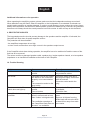
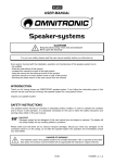
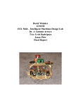
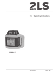
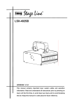
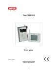
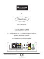
&
BlueAmps
Users MANUAL
Camplifier 90
x 90W stereo or 1 x 180W bridged add on
power amplifier module
for the Kemper Profiling Amplifier
&
input
BlueAmps
Bridged
Mode
CAMPLIFIER 290
Power
VAC / 50-60Hz / 210VA
Fuse
replace with same type only!
Serial #
right / both / bridge
left
speaker
Risk of electric shock!
Do not operate outside of KPA enclosure!
Equipment must be earthed.
Do not expose to rain or moisture!
Minimal speaker impedance / power : 4 Ω / 90W
Signal Input
Connect speakers to this
socket ONLY for bridged
mode! Remove all other
speaker cables !
speaker
4 Ω / 90W
www.kpa-solutions.com
8 Ω / 180W
Keep this manual for future needs!
Page 1
www.kpa-solutions.com
Table of Contents
Chapter
1. Introduction
2. Safety Instructions
3. Legal Instructions
4. Operating Determinations
5. Description
6. Installation
7. Connections
8. Operation
9. Protective Circuits
10. Trouble Shooting
11. Cleaning and Maintenance
12. Technical Specifications
Page
3
3-6
6
8
9 - 10
11 - 13
14
19
20
20
21
22
Page www.kpa-solutions.com
English
USER MANUAL
CA U T I ON !
Keep this device away from rain and moisture!
Unplug mains lead before opening the housing!
Every person involved with the installation, operation and maintenance of this device has to
- be qualified
- follow the instructions of this manual
- consider this manual to be part of the total product
- keep this manual for the entire service life of the product
- pass this manual on to every further owner or user of the product
- download the latest version of the user manual from the Internet
1 INTRODUCTION
Thank you for having chosen a CAMPLIFIER 290 add on amplifier module. If you follow the instructions given in this manual, we can assure you that you will enjoy this device for many years.
Unpack your amplifier.
2 SAFETY INSTRUCTIONS
CA U T I ON !
Be careful with your operations. With a dangerous voltage you can suffer a dangerous
electric shock when touching the wires!
This device has left our premises in absolutely perfect condition. In order to maintain this condition
and to ensure a safe operation, it is absolutely necessary for the user to follow the safety instructions
and warning notes written in this user manual.
Important:
Damages caused by the disregard of this user manual are not subject to warranty. The dealer will not
accept liability for any resulting defects or problems.
If the device has been exposed to drastic temperature fluctuation (e.g. after transportation), do not
switch it on immediately. The arising condensation water might damage your device. Leave the device switched off until it has reached room temperature.
Page www.kpa-solutions.com
Please make sure that there are no obvious transport damages. Should you notice any damages
on the A/C connection cable or on the casing, do not take the device into operation and immediately
consult your local dealer.
This device falls under protection-class I. The power plug must only be plugged into a protection
class I outlet. The voltage and frequency must exactly be the same as stated on the device. Wrong
voltages or power outlets can lead to the destruction of the device and to mortal electrical shock.
Always plug in the power plug least. The power plug must always be inserted without force. Make
sure that the plug is tightly connected with the outlet.
Never let the power cord come into contact with other cables! Handle the power cord and all connections with the mains with particular caution! Never touch them with wet hands, as this could lead
to mortal electrical shock.
Never modify, bend, strain mechanically, put pressure on, pull or heat up the power cord. Never
operate next to sources of heat or cold. Disregard can lead to power cord damages, fire or mortal
electrical shock.
The cable insert or the female part in the device must never be strained. There must always be sufficient cable to the device. Otherwise, the cable may be damaged which may lead to mortal damage.
Make sure that the power cord is never crimped or damaged by sharp edges. Check the device and
the power cord from time to time.
If extension cords are used, make sure that the core diameter is sufficient for the required power
consumption of the device. All warnings concerning the power cords are also valid for possible extension cords.
Always disconnect from the mains, when the device is not in use or before cleaning it. Only handle
the power cord by the plug. Never pull out the plug by tugging the power-cord. Otherwise, the cable
or plug can be damaged leading to mortal electrical shock. If the power plug or the power switch is
not accessible, the device must be disconnected via the mains.
If the power plug or the device is dusty, the device must be taken out of operation, disconnected and
then be cleaned with a dry cloth. Dust can reduce the insulation which may lead to mortal electrical
shock. More severe dirt in and at the device should only be removed by a specialist.
There must never enter any liquid into power outlets, extension cords or any holes in the housing of
the device. If you suppose that also a minimal amount of liquid may have entered the device, it must
immediately be disconnected. This is also valid, if the device was exposed to high humidity. Also if
the device is still running, the device must be checked by a specialist if the liquid has reduced any
insulation. Reduced insulation can cause mortal electrical shock.
There must never be any objects entering into the device. This is especially valid for metal parts. If
any metal parts like staples or coarse metal chips enter into the device, the device must be taken
out of operation and disconnected immediately. Malfunction or short-circuits caused by metal parts
may cause mortal injuries.
The device and all connections have to be lightning protected.
Page www.kpa-solutions.com
Only connect the device when the power switch is off.
Never connect the inputs or outputs to any power source (batteries, etc.)
Never connect output to output.
Before the device is switched on all faders and volume controls have to be set to “0” or “min” position.
Never connect the Speaker OUT of the CAMPLIFIER 290 to the signal OUT of the Kemper Profiling Amplifier!!
This would cause damage to the Kemper Profiling Amplifiers and the CAMPLIFIER 290!
Page www.kpa-solutions.com
CAUTION: Turn the amplifier on last and off first!
Please note that damages caused by manual modifications on the device or unauthorized operation
by unqualified persons are not subject to warranty.
Keep away children and amateurs!
There are no serviceable parts inside the device.
Maintenance and service operations are only to be carried out by authorized dealers.
3 LEGAL INSTRUCTIONS
Operating a guitar amplification system can produce extremely high noise levels that may cause a
permanent hearing loss. The legal instructions for using an amplification system vary from country to
country. The user must always inform himself on the legal instructions valid in his country and apply
them to his situation.
Always monitor the sound pressure level when operating an amplification system in discotheques,
concerts etc. Never exceed the permissible noise level exposures as specified by your authorities.
The monitoring of the noise levels must be documented in an appropriate way.
In Germany, the following instructions are binding:
Strafgesetzbuch § 223 ff: bundesrecht.juris.de/bundesrecht/stgb
TA Lärm: www.umweltdaten.de
DIN 15905-5: www.din.de
Arbeitsstättenverordnung § 15: www.lgl.bayern.de/arbeitsschutz
Berufsgenossenschaftliche Vorschrift BGV B3: www.pr-o.info
VDI-Richtlinie: VDI 2058 Blatt 2: www.vdi.de
Hearing damage caused by high noise levels can be treated as physical injury and persecuted by
law.
Please note that the organizer is responsible for keeping to a specified noise level. If this noise level
will be exceeded, the event may be cancelled immediately.
If the organizer does not fulfil his safety duties, he is reliable by civil law for any damages occurred,
e.g.:
Pay the treatment costs of the damaged person.
Pay a smart money to the damaged person.
Economic damage caused can be demanded from the operator of the amplification system.
If hired persons work with amplification systems: the noise levels of music events are almost always
too high. This is why the entrepreneur has to set up warning signs and provide hearing protectors.
The staff has to use these.
Please note: Tilman Ritter / RITTER Amplification / Marco Wendel / BlueAmps and KPA-Solutions
cannot be made liable for damages caused by incorrect installations and excessive noise levels!
Page www.kpa-solutions.com
English
3.1 Information on hearing loss
More and more young people suffer from hearing loss of 25 decibel or more, mainly caused by loud
music from portable music players, discotheques, rock conocerts or band rehersals. Everybody
operating amplification systems should know to what sound pressure levels he exposes his or the
audience’s hearing. As an average levels between 75 and 105 dB(A) in the discotheque or 95 and
115 dB(A) at a rock concert are reached. Individual peaks can exceed the pain level at 130 dB(A).
Such levels are typical for motor chainsaws or jack hammers.
It is important to know that doubling the power increases the noise level by 3 dB. The human hearing
does only recognizes a doubling of the sound level when the noise level is increased by 10 dB. Damaging the hearing does not depend on the sound level but on the noise level and starts way before
the pain level.
Many people deceive themselves by thinking that noise is something they can get accustomed to.
It is possible that a positive opinion of a certain noise can reduce the physiological reaction, but the
slow impacts on the inner hearing must not be neglected: over stimulation and continuous elimination
of the Cortic organ’s hair cells.
The reason why some people have got accustomed to a certain noise level and are no longer disturbed is that they have already suffered a hearing damage. This damage make the insensitive to
those frequencies forming the loudest part of the noise. Getting accustomed to noise does not mean
anything other than trying to get along with the hearing loss in everyday life. The hearing loss itself
cannot be healed, it can only be compensated by hearing aids.
Subjectively, the hearing loss feels like dampened ears. This effect weakens with the time, but a loss
in hearing sensitivity often remains.
In order to relax the hearing sufficiently, the noise level should not exceed 70 dB(A) for 10 hours.
Higher noise levels during this relaxing period can prevent the relaxation and promote a permanent
hearing damage (Tinitus) or hearing loss.
Therefore: Whoever wants to maintain his hearing should use hearing protectors!
Page www.kpa-solutions.com
English
4 OPERATING DETERMINATIONS
The CAMPLIFIER 290 add on amplifier module has been specially designed for the operation
mounted INSIDE of the Kemper Profiling Amplifier (KPA).
Any operation of the CAMPLIFIER 290 outside of the KPA is forbidden!
The Camplifier 290 is designed to be used as a stereo amplifier with two separate channels.
Both channel can power a 4 ohms speaker cabinet to 90Wrms.
Both channles can be run in bridged mode on a single speaker output with twice the output
power as a single stereo channel (180W). If the speaker is connected to the bridged mode output, the speaker cabinets from the stereo speaker outputs must be disconnected.
The CAMPLIFIER 290 may be used to provide power amplification to speaker cabinets. The signal source must be the Kemper Profiling Amplifier (KPA).
Please note that the speaker systems connected to the Camplifier must provide a minimal impedance of 4 ohms and must be capable of handling at least 90Wrms.
Speaker system impedances bellow 8 ohms might damage the CAMPLIFIER 290!
Speaker systems with a specified max. power handling capacity of less than 180W might be
damaged by the CAMPLIFIERs high power output!
Bridged Mode :
In bridged mode, the seaker system connected to the Camplifier 290 must provide a minimal impedance of 8 ohms and must be capable of handling at least 90Wrms.
Speaker system impedances bellow 8 ohms might damage the CAMPLIFIER 290 if used in
brideged mode!
Speaker systems with a specified max. power handling capacity of less than 180W might
be damaged by the CAMPLIFIERs high power output!
This product is allowed to be operated with an alternating current of 230 V, 50 Hz and was designed for indoor use only.
This device is designed for mobile use and for permanent installations.
By operating amplifying systems, you can produce excessive sound pressure levels that may
lead to permanent hearing loss. Please refer to the explanations under “Legal instructions”.
Page www.kpa-solutions.com
Please note: operating an amplification system in public or industrial areas, a series of safety instructions have to be followed that this manual can only give in part. The operator must therefore inform
himself on the current safety instructions and consider them.
Do not shake the device. Avoid brute force when installing or operating the device.
When choosing the installation-spot, please make sure that the device is not exposed to extreme heat,
moisture or dust. There should not be any cables lying around. You endanger your own and the safety of
others!
This device must never be operated or stockpiled in surroundings where splash water, rain, moisture or
fog may harm the device.
Moisture or very high humidity can reduce the insulation and lead to mortal electrical shocks.
When using smoke machines, make sure that the device is never exposed to the direct smoke jet and is
installed in a distance of 0.5 meters between smoke machine and device.
The ambient temperature must always be between -5° C and +45° C. Keep away from direct insulation (particularly in cars) and heaters.
The relative humidity must not exceed 50 % with an ambient temperature of 45° C.
This device must only be operated in an altitude between -20 and 2000 m over NN.
The ambient contamination must never exceed level 1 and must not be conducting, only dry.
Never use the device during thunderstorms. Over voltage could destroy the device. Always disconnect the device during thunderstorms.
Operate the device only after having familiarized with its functions. Do not permit operation by persons not qualified for operating the device. Most damages are the result of unprofessional operation!
Never use solvents or aggressive detergents in order to clean the device! Rather use a soft and
damp cloth.
Please use the original packaging if the device is to be transported.
Never remove the serial barcode from the device as this would make the guarantee void. Please consider that unauthorized modifications on the speaker system are forbidden due to safety reasons!
If this device will be operated in any way different to the one described in this manual, the product
may suffer damages and the guarantee becomes void. Furthermore, any other operation may lead to
dangers like short- circuit, burns, electric shock, hearing loss etc.
5 DESCRIPTION
5.1 Features
Stereo add on amplifier module for the Kemper Profiling Amplifier
• Complete protection set against short-circuit, overheat, over voltage, overload
• Fan cooling
• Signal inputs via 6.3 mm mounting jacks
• Speaker outputs via lockable Speakon sockets
• Designed to fit into the open space at the KPAs back side
Page www.kpa-solutions.com
English
2
4
5.2 Operating elements and connections
&
input
BlueAmps
Bridged
Mode
CAMPLIFIER 290
Power
VAC / 50-60Hz / 210VA
Fuse
replace with same type only!
Serial #
Signal Input
right / both / bridge
left
Connect speakers to this
socket ONLY for bridged
mode! Remove all other
speaker cables !
speaker
Risk of electric shock!
Do not operate outside of KPA enclosure!
Equipment must be earthed.
Do not expose to rain or moisture!
Minimal speaker impedance / power : 4 Ω / 90W
speaker
4 Ω / 90W
www.kpa-solutions.com
8 Ω / 180W
3
5
1
1 AC input with fuse holder Used to plug the supplied power cord in. Only replace the fuse when the
device is disconnected from mains. Only use fuses of the same rating and power (1AT). The correct
fuse value is specified on the rear panel.
2 Power on/off switch
3 Speaker connectors Speaker jacks for stereo operation and mono operation using the signal supplied to the right signal 6,3mm jack input only.
Do never connect speaker cabinets to these sockets if the Camplifier is used in bridged mode!
4 Input jacks for the right and left channel for stereo operation. The right input jack provides signal to
both speaker outputs if the eft input jack is not used.
The right signal input jack provides signal to the speaker output if the Camplifier is used in bridged
mode.
5 Speaker connector Speaker jack for bridged mode using the signal supplied to the right signal
6,3mm jack input.
Page 10
www.kpa-solutions.com
English
6. Installation / Assembly
Preface :
The CAMPLIFIER 90 is designed to operate as an add on module inside the Kemper Profiling
Amplifier.
Any operation outside of the Kemper Profiling Amplifier can cause damage to equipment and cause
mortal electrical shock.
Should you experience any difficulties when installing the CAMPLIFIER 90 into the Kemper Profiling Amplifier , please contact our technical support at :
Tilman Ritter
RITTER Amplification
Veteranenstrasse 3
01139 Dresden
Tel. : 0351 160 51 98
[email protected]
Please do NEVER connect the power cord to the CAMPLIFIER 90 when the unit has not been assembled into the Kemper Profiling Amplifier correctly!
6.1 Preparation prior Installation
Check the upper chamber at the back side of the Kemper Profiling Amplifier (KPA) for objects such
as cables, paper, guitar picks, guitar strings etcetera. Remove all objects from this chamber!
Page 11
www.kpa-solutions.com
English
Remove all 8 screws that surround the KPAs back chamber. You will need a TORX 10 screwdriver to do that.
Additionally to the power cord that has been delivered with your CAMPLIFIER 90, 8 small screws
have been delivered with it too.
Please find them and consign them close to your KPA together with a Phillips screwdriver apposite to
those 8 screws.
Consign the CAMPLIFIER 90 handy.
Make sure no objects such as packing material, tape, paper etcetera are attached to the CAMPLIFIER
90 any more. The CAMPLIFIERs fan wheel should turn freely and must not be blocked by any objects.
Page 1
www.kpa-solutions.com
English
6.2 Installation
Insert the CAMPLIFIER 90 slowly and carefully into the back chamber of the KPA.
It might be helpful to put the KPA carefully on its operation side for this.
Please make sure the CAMPLIFIER can be inserted smoothly and without any tension.
Align the 8 mounting holes of the CAMPLIFIER 90 as good as possible to the threaded holes at
the back sheet metal of the KPA.
&
input
BlueAmps
Bridged
Mode
CAMPLIFIER 290
Power
VAC / 50-60Hz / 210VA
right / both / bridge
leftonly!
replace with same type
Fuse
Serial #
Signal Input
Connect speakers to this
socket ONLY for bridged
mode! Remove all other
speaker cables !
speaker
Risk of electric shock!
Do not operate outside of KPA enclosure!
Equipment must be earthed.
Do not expose to rain or moisture!
speaker
4 Ω / 90W
Minimal speaker impedance / power : 4 Ω / 90W
www.kpa-solutions.com
8 Ω / 180W
Screw the Camplifier onto the KPA with the 8 screws that have been delivered with the Camplifier.
Congratulations! You have successfully installed the CAMPLIFIER 90!
&
input
BlueAmps
Bridged
Mode
CAMPLIFIER 290
Power
Fuse
VAC / 50-60Hz / 210VA
right / both / bridge
leftonly!
replace with same type
Serial #
Risk of electric shock!
Do not operate outside of KPA enclosure!
Equipment must be earthed.
Do not expose to rain or moisture!
Minimal speaker impedance / power : 4 Ω / 90W
Signal Input
Connect speakers to this
socket ONLY for bridged
mode! Remove all other
speaker cables !
speaker
speaker
4 Ω / 90W
www.kpa-solutions.com
8 Ω / 180W
Page 13
www.kpa-solutions.com
English
7 CONNECTIONS
All connections have to be made or changed only if the amplifier is switched off!
7.1 Inputs
Connect the output of the KPA to one of the jacks to the Camplifiers INPUT sockets.
The input signal should have line level.
Information on installing speaker cables
Input cables should be short and direct, since high frequencies will mostly be absorbed if the cables are unnecessarily long. Besides that a longer cable may lead to humming and noise trouble.
If long cable runs are unavoidable, you should use balanced cables.
Occupation jack plug:
Unbalanced use of
1/4" jack plugs
Tip =
hot (+)
Sleeve =
Ground / Shield
Tip
Sleeve
Strain relief clamp
For connection of balanced and
unbalanced plugs, ring and sleeve have
to be bridged at a stereo plug.
Page 14
www.kpa-solutions.com
English
7.2 Speaker outputs
In stereo mode, the amplifier can operate two speakers or two speaker groups.
For connecting speakers, Speaker jacks are provided. When using the Speaker jacks, turn each plug to
the right until it locks into place. For unlocking, pull the unlock button and turn the plug to the left.
• Occupation Speaker socket:
Example for the calculation number of speakers/impedance
Number of Speakers
1 Speaker at 4 ohms
2 Speakers at 4 ohms
2 Speakers at 4 ohms
1 Speaker at 8 ohms
2 Speakers at 8 ohms
2 Speakers at 8 ohms
Impedance
4 ohms
2 ohms parallel wired
8 ohms connected in series
8 ohms
4 ohms parallel wired
16 ohms connected in series
The Speakers Impedance must be greater than 4 ohms / channel at all times in stereo mode !
The Speakers Impedance must be greater than 8 ohms at all times in bridged mode !
Information on choosing appropriate connection cables
• Speaker systems must only be connected via sufficiently dimensioned cables. Too thin cables lead to
cable heat up or enormous power loss and loss in sound quality.
• For all speaker systems up to 400 Watts, we recommend a cable diameter of 2.5 mm2, for all other
speaker cables 4 mm2.
• A high damping factor of your amplifier supplies a clear sound reproduction. Unnecessarily long and
thin cables will influence the damping factor and thus the low frequencies in a negative way. In order to
safeguard good sound quality, the damping factor should lie around 50. The longer a cable has to be,
the thicker it should be. In this respect, a damping factor of 200 will be reduced to 47 (8 ohms) when
using a 10 m long, 2.5 mm2 speaker cable. The power loss at 8 ohms is 1.63 %, at 4 ohms 3.25 % and
at 2 ohms even 6.5 %.
• The maximum cable length is 30 meters!
Page 15
www.kpa-solutions.com
English
Information on installing speaker cables
• Always treat cables carefully and protect them from damages during transportation.
• Install cables always in a structured way and protect them from damage.
• Cables must be installed in a way that no person can stumble over them. Always fix cables with an
appropriate tape.
• Both cables should be of the same kind.
• Both cables should have the same length.
• Both cables should be installed directly (no loops, S-shaped over lengths)
• Always install the cables far away from power cables (never closely parallel)
• Never put heavy objects like speaker systems, flight cases etc. on cables.
• Never wind up cables tightly around the elbow, but rather sleek with an interior diameter of 0 to 30
cm.
7.2.1 Stereo Operation
The most frequently used operating mode of the Camplifier 90 might be stereo operation, where both
stereo channels are operated independent of each other. The highest output power during stereo operation is achieved by connecting 4 ohms speakers. With 8 or 16 ohms speakers, the output power will be
slightly reduced. For stereo operation, use both speaker pairs at the speaker output sockets and insert
signal jacks into both input sockets at the Camplifier 90.
&
input
BlueAmps
Bridged
Mode
CAMPLIFIER 290
Power
VAC / 50-60Hz / 210VA
Fuse
replace with same type only!
Serial #
right / both / bridge
left
speaker
Risk of electric shock!
Do not operate outside of KPA enclosure!
Equipment must be earthed.
Do not expose to rain or moisture!
Signal Input
Connect speakers to this
socket ONLY for bridged
mode! Remove all other
speaker cables !
speaker
Minimal speaker impedance / power : 4 Ω / 90W
4 Ω / 90W
www.kpa-solutions.com
8 Ω / 180W
Scheme : stereo operation
Page 16
www.kpa-solutions.com
English
7.2.2 Mono Operation (both stereo speakers operate with the same input signal)
Both speaker outputs will be driven by the same input signal. This input signal is fed to the RIGHT signal input socket (marked yellow at the connection scheme at the Camplifier).
The highest output power during stereo operation is achieved by connecting 4 ohms speakers. With 8
or 16 ohms speakers, the output power will be slightly reduced.
&
input
BlueAmps
Bridged
Mode
CAMPLIFIER 290
Power
VAC / 50-60Hz / 210VA
Fuse
replace with same type only!
Serial #
right / both / bridge
left
Risk of electric shock!
Do not operate outside of KPA enclosure!
Equipment must be earthed.
Do not expose to rain or moisture!
Minimal speaker impedance / power : 4 Ω / 90W
Signal Input
Connect speakers to this
socket ONLY for bridged
mode! Remove all other
speaker cables !
speaker
speaker
4 Ω / 90W
www.kpa-solutions.com
8 Ω / 180W
Scheme : Mono / both operation
Page 17
www.kpa-solutions.com
English
7.2.3 Bridged mode operation
Only a single speaker is connected to bridged mode speaker output socket.
For this operation mode , please use the right channels signal input
The highest output power during stereo operation is achieved by connecting 8 ohms speakers. With 16
ohms speakers the output power will be slightly reduced.
Do not connenct speaker cabinets with an impedance < 8 ohms to the bridged mode speaker
out put socket!
Do not connect speaker cabinets to the speaker output sockets of the left and right channel
when the Camplifier is used in bridged mode!
&
input
BlueAmps
Bridged
Mode
CAMPLIFIER 290
Power
VAC / 50-60Hz / 210VA
Fuse
replace with same type only!
Serial #
right / both / bridge
left
speaker
Risk of electric shock!
Do not operate outside of KPA enclosure!
Equipment must be earthed.
Do not expose to rain or moisture!
Minimal speaker impedance / power : 4 Ω / 90W
Signal Input
Connect speakers to this
socket ONLY for bridged
mode! Remove all other
speaker cables !
speaker
4 Ω / 90W
www.kpa-solutions.com
8 Ω / 180W
scheme : bridged mode
Page 18
www.kpa-solutions.com
English
7.3 Connection with the mains
Finally connect the device to the mains with the supplied mains cable. The occupation of the connection cables is as follows:
brown wire - life wire - L
blue wire - neutral - N
yellow/green wire - protective earth
The earth has to be connected! If the device will be directly connected with the local power supply network, a disconnection switch with a minimum opening of 3 mm at every pole has to be included in the
permanent electrical installation. The device must only be connected with an electric installation carried
out in compliance with the IEC standards. The electric installation must be equipped with a Residual
Current Device (RCD) with a maximum fault current of 30 mA.
8. OPERATION
8.1 Selecting the operating mode
Connect the signal inputs and the speaker connections apposite to the operation mode you want to
choose.
- Stereo (refer to 7.2.1)
- Mono / Both (refer 7.2.1)
- Bridged mode (refer to 7.2.3)
8.2 Switching on/off
To prevent loud switching noise, always switch on all other units of the amplifier system before switching on the power amplifier. After operation, switch off the power amplifier first. Prior to switching on set
the level controls at the KPA to minimum. Then switch on the Camplifier with the power switch. The
power switch will be light green. If it does not, check if the amplifier is connected to the mains correctly.
8.3 Adjusting the level
Carefully increase the volume by turning the volume control at the KPA higher slowly until you reach
your desired volume level. There should be no loud humming. Should humming persist, check the connection cables between the Camplifier and the KPA (switch off components before).
Page 19
www.kpa-solutions.com
English
Additional information on the operation
When operating the amplifying system, please make sure that the loudspeakers always sound well.
When distortions can be heard, either the amplifier or the loudspeaker is overloaded. Overloads can
quickly lead to amplifier or speaker damage. In order to avoid damage, please reduce the volume immediately when distortions can be heard. When speaker systems are destroyed by overload, the guarantee
becomes void. Always check the sound pressure level with a meter in order to keep to the threshold.
9. PROTECTIVE CIRCUITS
The integrated protective circuits prevent damage to the speakers and the amplifier. If activated, the
Camplifier will shut down its power amplifier section.
The protection will be activated if:
- the amplifiers temperature is too high
- a short circuit and therefore a too high current in the speakers output occurs
If the Camplifier shuts down during operation, the amplifier has to be switched off and the cause of the
fault has to be removed.
The cause could be a damaged speaker cable, speaker plug, broken speaker chassis, a to low speaker
impedance or an insufficient ventilation at the back of the Camplifier.
.
10. Trouble Shooting
Problem
No Power.
No Sound.
Fan does not work, Power
switch does not light up.
Camplifier shuts down during
operation
Cause
The power cord is not connected.
The power cord of the respective device is not connected
properly or not connected at
all.
The connection socket or the
plug is dirty.
The power cord is not connected.
Fuse is broken.
Speaker impedance is < 4
ohms in stereo mode or less
than 8 ohms in bridged mode.
The ventilation openings at
the Camplifiers back plate are
blocked - no ventilation.
Page 20
www.kpa-solutions.com
Remedy
Check the power cordand
any extension cables.
Check the power cord and if
the plugs are tightly connected
with the sockets.
Clean the socket and/or the
plug.
Please check if the power
is available.
Check the fuse
Check the speakers impedance.
Remove all objects from the
KPAs back and move the KPA
at least 20cm away from walls
an curtains.
English
11. CLEANING AND MAINTENANCE
DA N GER T O L I FE!
Disconnect from mains before starting maintenance operation!
We recommend a frequent cleaning of the device. Please use a soft lint-free and moistened cloth.
Never use alcohol or solvents!
There are no serviceable parts inside the device except for the fuse. Maintenance and service operations are only to be carried out by authorized dealers.
11.1 Replacing the fuse
If the fine-wire fuse of the device fuses, only replace the fuse by a fuse of same type and rating.
Before replacing the fuse, unplug mains lead.
Procedure:
Step 1: Open the fuse holder on the rear panel with a fitting screwdriver.
Step 2: Remove the old fuse from the fuse holder.
Step 3: Install the new fuse in the fuse holder.
Step 4: Replace the fuse holder in the housing.
Should you need any spare parts, please use genuine parts.
If the power supply cable of this device becomes damaged, it has to be replaced by a special power
supply cable available at your dealer.
Should you have further questions, please contact us or your dealer.
Contact information:
Tilman Ritter
RITTER Amplification
Veteranenstrasse 3
01139 Dresden
Tel. : 0351 160 51 982
[email protected]
Page 21
www.kpa-solutions.com
English
Power supply
Power consumption
Audio power output RMS at 2 x 4 ohms
Bridged mode output RMS 1 x 8 ohms
Frequency range
Damping factor
Distortion factor
Noise voltage
Channel separation
Input sensitivity
Input voltage
Input impedance
Input sockets
Speaker output connection
Minimum speaker impedance
Control elements
Protection circuits
Dimensions
Weight
230 V AC, 50 Hz ~
210W max.
2 x 90W
1 x 180W
25Hz – 25kHz +/- 0.5dB
>350
THD 1% @ max. RMS Leistung
<40uVrms unweighted
79dB @ 1kHz and 1W
0,77V
max. 21 dBV/9V
20 kohms
2 x 1/4” unbalanced
2 x Speakon socket for stereo
1 x Speakon socket for bridged mode
4 ohms / channel stereo
8 ohms bridged mode
Power switch
Over current, Over voltage, Over temperature
350x85x77mm (13,8”x3,4”x3”)
1kg (2,2 lbs)
Please note: Every information is subject to change without prior notice.
Page 22
www.kpa-solutions.com