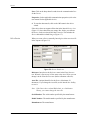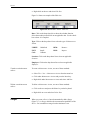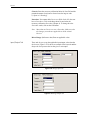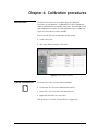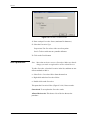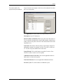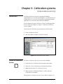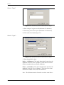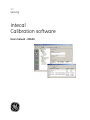
1
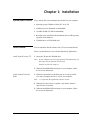
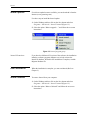
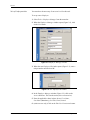
GE
Sensing
Intecal
Calibration software
User manual - K0420
Issue 1
Safety
Before you use Intecal, make sure that you read and understand all the
related data. This includes: the applicable local safety procedures, the
instructions for the equipment you are using with Intecal, and this
publication.
When you use equipment with Intecal, make sure that it is serviceable
and that it is in its normal condition for safe operation.
Before you start an operation or procedure in this publication, make
sure that you have the necessary skills (if necessary, with
qualifications from an approved training establishment). Follow good
engineering practice at all times.
Copyright
© 2006 General Electric Company. All rights reserved.
Trademarks
All product names are trademarks of their respective companies.
iii
Issue 1
Software purpose
Registration
Intecal is available as a multi-lingual calibration software program
that you can use on a Windows® PC (Chapter 1). You can use Intecal
for these tasks:
•
Manage the maintenance and calibration of all the measurement
devices for a specified business location.
•
Set up a schedule of calibration work for different employees.
•
Upload and download data to and from portable calibrators that
have a serial communications function (Druck, Ruska, or devices
with a Field Calibrator Interface - FCINTF).
•
Manage the calibration records for devices that do not have a
serial communications function (Manual Data Entry).
•
Inspect your calibration history records. You can also make a
permanent record of each calibration report. For example: For ISO
9000 quality control procedures.
•
(Intecal-Advanced only) Set up automatic calibration systems to
make full use of your GE Digital Pressure Controllers (Ruska and
Druck).
•
(Intecal-Advanced only) Calibrate a device or a group of devices
that have a serial communications function (Druck, Ruska, or
FCINTF).
•
(Intecal-Advanced only) Make calibration adjustments to a device
or a group of devices that have a serial communications function
(Druck, Ruska, or FCINTF).
The Intecal Calibration software (from a CD or downloaded from the
Web) is available for you to try as a fully functional product, with no
obligation, for a period of 30 days. The trial period starts on the day it
is first used - not on the day it is installed.
To change the 30 license to a full license, please purchase an unlock
key from the GE Sensing sales team at: www.gesensing.com.
iv
Issue 1
Table of Contents
Safety . . . . . . . . . . . . . . . . . . . . . . . . . . . . . . . . . . . . . . . . . . . . . . . . . . . . . . . . . . . . . . . . . . . . . . . .iii
Copyright . . . . . . . . . . . . . . . . . . . . . . . . . . . . . . . . . . . . . . . . . . . . . . . . . . . . . . . . . . . . . . . . . . . . .iii
Trademarks . . . . . . . . . . . . . . . . . . . . . . . . . . . . . . . . . . . . . . . . . . . . . . . . . . . . . . . . . . . . . . . . . . .iii
Software purpose . . . . . . . . . . . . . . . . . . . . . . . . . . . . . . . . . . . . . . . . . . . . . . . . . . . . . . . . . . . . . . . iv
Registration . . . . . . . . . . . . . . . . . . . . . . . . . . . . . . . . . . . . . . . . . . . . . . . . . . . . . . . . . . . . . . . . . . . iv
Table of Contents. . . . . . . . . . . . . . . . . . . . . . . . . . . . . . . . . . . . . . . . . . . . . . . . . . . . . . . . . . . . . . . v
Chapter 1: Installation
System specification . . . . . . . . . . . . . . . . . . . . . . . . . . . . . . . . . . . . . . . . . . . . . . . . . . . . . . . . . . .1-1
Install Intecal . . . . . . . . . . . . . . . . . . . . . . . . . . . . . . . . . . . . . . . . . . . . . . . . . . . . . . . . . . . . . . . . .1-1
Install Intecal from a CD: . . . . . . . . . . . . . . . . . . . . . . . . . . . . . . . . . . . . . . . . . . . . . . . . . . . .1-1
Install Intecal from the Web: . . . . . . . . . . . . . . . . . . . . . . . . . . . . . . . . . . . . . . . . . . . . . . . . .1-1
Intecal updates . . . . . . . . . . . . . . . . . . . . . . . . . . . . . . . . . . . . . . . . . . . . . . . . . . . . . . . . . . . . . . . .1-2
Intecal-W versions . . . . . . . . . . . . . . . . . . . . . . . . . . . . . . . . . . . . . . . . . . . . . . . . . . . . . . . . .1-2
After installation . . . . . . . . . . . . . . . . . . . . . . . . . . . . . . . . . . . . . . . . . . . . . . . . . . . . . . . . . . . . . .1-2
Intecal uninstall . . . . . . . . . . . . . . . . . . . . . . . . . . . . . . . . . . . . . . . . . . . . . . . . . . . . . . . . . . . . . . .1-2
Chapter 2: Getting started
Introduction . . . . . . . . . . . . . . . . . . . . . . . . . . . . . . . . . . . . . . . . . . . . . . . . . . . . . . . . . . . . . . . . . .2-1
Start Intecal . . . . . . . . . . . . . . . . . . . . . . . . . . . . . . . . . . . . . . . . . . . . . . . . . . . . . . . . . . . . . . . . . .2-1
Screen structure . . . . . . . . . . . . . . . . . . . . . . . . . . . . . . . . . . . . . . . . . . . . . . . . . . . . . . . . . . . . . . .2-2
Program structure . . . . . . . . . . . . . . . . . . . . . . . . . . . . . . . . . . . . . . . . . . . . . . . . . . . . . . . . . . . . .2-3
Employee Manager . . . . . . . . . . . . . . . . . . . . . . . . . . . . . . . . . . . . . . . . . . . . . . . . . . . . . . . . . . . .2-3
Permission levels. . . . . . . . . . . . . . . . . . . . . . . . . . . . . . . . . . . . . . . . . . . . . . . . . . . . . . . . . . .2-3
Set up Employee data . . . . . . . . . . . . . . . . . . . . . . . . . . . . . . . . . . . . . . . . . . . . . . . . . . . . . . .2-4
Change Employee data . . . . . . . . . . . . . . . . . . . . . . . . . . . . . . . . . . . . . . . . . . . . . . . . . . . . . .2-5
Set up your password . . . . . . . . . . . . . . . . . . . . . . . . . . . . . . . . . . . . . . . . . . . . . . . . . . . . . . .2-6
Delete an Employee . . . . . . . . . . . . . . . . . . . . . . . . . . . . . . . . . . . . . . . . . . . . . . . . . . . . . . . .2-6
Select a language . . . . . . . . . . . . . . . . . . . . . . . . . . . . . . . . . . . . . . . . . . . . . . . . . . . . . . . . . . . . . .2-7
Chapter 3: Plant Structure
Introduction . . . . . . . . . . . . . . . . . . . . . . . . . . . . . . . . . . . . . . . . . . . . . . . . . . . . . . . . . . . . . . . . . .3-1
Locations . . . . . . . . . . . . . . . . . . . . . . . . . . . . . . . . . . . . . . . . . . . . . . . . . . . . . . . . . . . . . . . . . . . .3-2
Create a Sub-location . . . . . . . . . . . . . . . . . . . . . . . . . . . . . . . . . . . . . . . . . . . . . . . . . . . . . . .3-2
Edit a Sub-location . . . . . . . . . . . . . . . . . . . . . . . . . . . . . . . . . . . . . . . . . . . . . . . . . . . . . . . . .3-2
Rename a Sub-location . . . . . . . . . . . . . . . . . . . . . . . . . . . . . . . . . . . . . . . . . . . . . . . . . . . . . .3-3
Delete a Sub-location . . . . . . . . . . . . . . . . . . . . . . . . . . . . . . . . . . . . . . . . . . . . . . . . . . . . . . .3-3
Tags . . . . . . . . . . . . . . . . . . . . . . . . . . . . . . . . . . . . . . . . . . . . . . . . . . . . . . . . . . . . . . . . . . . . . . . .3-3
Create a Tag . . . . . . . . . . . . . . . . . . . . . . . . . . . . . . . . . . . . . . . . . . . . . . . . . . . . . . . . . . . . . .3-3
Edit a Tag . . . . . . . . . . . . . . . . . . . . . . . . . . . . . . . . . . . . . . . . . . . . . . . . . . . . . . . . . . . . . . . .3-4
Rename a tag. . . . . . . . . . . . . . . . . . . . . . . . . . . . . . . . . . . . . . . . . . . . . . . . . . . . . . . . . . . . . .3-4
Delete a tag . . . . . . . . . . . . . . . . . . . . . . . . . . . . . . . . . . . . . . . . . . . . . . . . . . . . . . . . . . . . . . .3-4
v
Issue 1
Devices. . . . . . . . . . . . . . . . . . . . . . . . . . . . . . . . . . . . . . . . . . . . . . . . . . . . . . . . . . . . . . . . . . . . . 3-5
Create a device (Manual method) . . . . . . . . . . . . . . . . . . . . . . . . . . . . . . . . . . . . . . . . . . . . . 3-5
Create a device (New Device Wizard method) . . . . . . . . . . . . . . . . . . . . . . . . . . . . . . . . . . . 3-5
Edit a Device . . . . . . . . . . . . . . . . . . . . . . . . . . . . . . . . . . . . . . . . . . . . . . . . . . . . . . . . . . . . . 3-6
Rename a device . . . . . . . . . . . . . . . . . . . . . . . . . . . . . . . . . . . . . . . . . . . . . . . . . . . . . . . . . . 3-7
Delete a Device . . . . . . . . . . . . . . . . . . . . . . . . . . . . . . . . . . . . . . . . . . . . . . . . . . . . . . . . . . . 3-7
Maintenance actions. . . . . . . . . . . . . . . . . . . . . . . . . . . . . . . . . . . . . . . . . . . . . . . . . . . . . . . . . . . 3-7
Edit a maintenance action . . . . . . . . . . . . . . . . . . . . . . . . . . . . . . . . . . . . . . . . . . . . . . . . . . . 3-7
Create a maintenance action . . . . . . . . . . . . . . . . . . . . . . . . . . . . . . . . . . . . . . . . . . . . . . . . . 3-8
Delete a maintenance action . . . . . . . . . . . . . . . . . . . . . . . . . . . . . . . . . . . . . . . . . . . . . . . . . 3-8
Ranges . . . . . . . . . . . . . . . . . . . . . . . . . . . . . . . . . . . . . . . . . . . . . . . . . . . . . . . . . . . . . . . . . . . . . 3-8
Create a Range. . . . . . . . . . . . . . . . . . . . . . . . . . . . . . . . . . . . . . . . . . . . . . . . . . . . . . . . . . . . 3-9
Edit a Range. . . . . . . . . . . . . . . . . . . . . . . . . . . . . . . . . . . . . . . . . . . . . . . . . . . . . . . . . . . . . . 3-9
Delete a Range. . . . . . . . . . . . . . . . . . . . . . . . . . . . . . . . . . . . . . . . . . . . . . . . . . . . . . . . . . . 3-12
Copy/move items . . . . . . . . . . . . . . . . . . . . . . . . . . . . . . . . . . . . . . . . . . . . . . . . . . . . . . . . . . . . 3-12
Chapter 4: Calibration procedures
Introduction . . . . . . . . . . . . . . . . . . . . . . . . . . . . . . . . . . . . . . . . . . . . . . . . . . . . . . . . . . . . . . . . .
Create a procedure . . . . . . . . . . . . . . . . . . . . . . . . . . . . . . . . . . . . . . . . . . . . . . . . . . . . . . . . . . . .
Edit a procedure . . . . . . . . . . . . . . . . . . . . . . . . . . . . . . . . . . . . . . . . . . . . . . . . . . . . . . . . . . . . . .
Procedure editor for proportional procedures . . . . . . . . . . . . . . . . . . . . . . . . . . . . . . . . . . . .
Procedure Editor for switch procedures . . . . . . . . . . . . . . . . . . . . . . . . . . . . . . . . . . . . . . . .
Rename a procedure. . . . . . . . . . . . . . . . . . . . . . . . . . . . . . . . . . . . . . . . . . . . . . . . . . . . . . . . . . .
Copy a procedure . . . . . . . . . . . . . . . . . . . . . . . . . . . . . . . . . . . . . . . . . . . . . . . . . . . . . . . . . . . . .
Delete a procedure . . . . . . . . . . . . . . . . . . . . . . . . . . . . . . . . . . . . . . . . . . . . . . . . . . . . . . . . . . . .
4-1
4-1
4-2
4-3
4-4
4-4
4-4
4-5
Chapter 5: Calibration systems
Introduction . . . . . . . . . . . . . . . . . . . . . . . . . . . . . . . . . . . . . . . . . . . . . . . . . . . . . . . . . . . . . . . . .
Create a Calibration System. . . . . . . . . . . . . . . . . . . . . . . . . . . . . . . . . . . . . . . . . . . . . . . . . . . . .
Wizard - Page 1 . . . . . . . . . . . . . . . . . . . . . . . . . . . . . . . . . . . . . . . . . . . . . . . . . . . . . . . . . . .
Wizard – Page 2. . . . . . . . . . . . . . . . . . . . . . . . . . . . . . . . . . . . . . . . . . . . . . . . . . . . . . . . . . .
Wizard – Page 3. . . . . . . . . . . . . . . . . . . . . . . . . . . . . . . . . . . . . . . . . . . . . . . . . . . . . . . . . . .
Edit a Calibration System. . . . . . . . . . . . . . . . . . . . . . . . . . . . . . . . . . . . . . . . . . . . . . . . . . . . . . .
Add, edit, delete calibration devices . . . . . . . . . . . . . . . . . . . . . . . . . . . . . . . . . . . . . . . . . . .
Add, edit, delete calibration variables . . . . . . . . . . . . . . . . . . . . . . . . . . . . . . . . . . . . . . . . . .
Rename a calibration system . . . . . . . . . . . . . . . . . . . . . . . . . . . . . . . . . . . . . . . . . . . . . . . . . . . .
Copy a calibration system . . . . . . . . . . . . . . . . . . . . . . . . . . . . . . . . . . . . . . . . . . . . . . . . . . . . . .
Delete a calibration system . . . . . . . . . . . . . . . . . . . . . . . . . . . . . . . . . . . . . . . . . . . . . . . . . . . . .
5-1
5-1
5-2
5-2
5-3
5-4
5-5
5-5
5-6
5-6
5-7
Chapter 6: Work Orders
Introduction . . . . . . . . . . . . . . . . . . . . . . . . . . . . . . . . . . . . . . . . . . . . . . . . . . . . . . . . . . . . . . . . .
Create a new Work Order. . . . . . . . . . . . . . . . . . . . . . . . . . . . . . . . . . . . . . . . . . . . . . . . . . . . . . .
Set up your Work Order data.. . . . . . . . . . . . . . . . . . . . . . . . . . . . . . . . . . . . . . . . . . . . . . . . . . . .
Add Devices to a Work Order . . . . . . . . . . . . . . . . . . . . . . . . . . . . . . . . . . . . . . . . . . . . . . . .
Add instructions to a Work Order . . . . . . . . . . . . . . . . . . . . . . . . . . . . . . . . . . . . . . . . . . . . .
Delete items from a Work Order . . . . . . . . . . . . . . . . . . . . . . . . . . . . . . . . . . . . . . . . . . . . . . . . .
Delete a Work Order . . . . . . . . . . . . . . . . . . . . . . . . . . . . . . . . . . . . . . . . . . . . . . . . . . . . . . . . . .
Upload/download data . . . . . . . . . . . . . . . . . . . . . . . . . . . . . . . . . . . . . . . . . . . . . . . . . . . . . . . .
vi
6-1
6-2
6-2
6-2
6-3
6-3
6-3
6-4
Issue 1
Chapter 7: Calibration
Introduction . . . . . . . . . . . . . . . . . . . . . . . . . . . . . . . . . . . . . . . . . . . . . . . . . . . . . . . . . . . . . . . . . .7-1
Calibration history . . . . . . . . . . . . . . . . . . . . . . . . . . . . . . . . . . . . . . . . . . . . . . . . . . . . . . . . . . . . .7-1
Calibration History records. . . . . . . . . . . . . . . . . . . . . . . . . . . . . . . . . . . . . . . . . . . . . . . . . . .7-2
Calibration History reports . . . . . . . . . . . . . . . . . . . . . . . . . . . . . . . . . . . . . . . . . . . . . . . . . . .7-3
Calibration - Manual Data Entry . . . . . . . . . . . . . . . . . . . . . . . . . . . . . . . . . . . . . . . . . . . . . . . . . .7-5
Calibration - Automatic . . . . . . . . . . . . . . . . . . . . . . . . . . . . . . . . . . . . . . . . . . . . . . . . . . . . . . . . .7-6
Automatic calibration - Plant Structure window. . . . . . . . . . . . . . . . . . . . . . . . . . . . . . . . . . .7-6
Automatic calibration - Work Order window . . . . . . . . . . . . . . . . . . . . . . . . . . . . . . . . . . . . .7-7
Calibration window. . . . . . . . . . . . . . . . . . . . . . . . . . . . . . . . . . . . . . . . . . . . . . . . . . . . . . . . .7-8
Calibration - Adjustment . . . . . . . . . . . . . . . . . . . . . . . . . . . . . . . . . . . . . . . . . . . . . . . . . . . . . . . .7-9
Calibration window (Adjustment) . . . . . . . . . . . . . . . . . . . . . . . . . . . . . . . . . . . . . . . . . . . .7-10
Customer service . . . . . . . . . . . . . . . . . . . . . . . . . . . . . . . . . . . . . . . . . . . . . . . . . . . . . . . . . . . . Back cover
vii
Issue 1
viii
Chapter 1: Installation
System specification
Install Intecal
To use Intecal, this is the minimum specification for your computer:
•
Operating system: Windows® 2000, NT 4.0 or XP
•
66 MHz processor (Pentium® recommended)
•
128 MB of RAM (256 MB recommended)
•
Hard disk space: 40 MB for the installation, then 10 MB to permit
expansion of the database
•
CD-ROM drive or DVD-ROM drive
You can install the Intecal software from a CD or from the Internet.
Before you install Intecal, close all other Windows® applications.
Install Intecal from a CD:
1. Insert the CD into the CD-ROM drive
Note: If your computer is not set up to open a CD automatically, you
must open the file from the CD yourself.
Double-click the file setup.exe
2. When the InstallShield Wizard opens on your computer, follow
the on-screen instructions.
Install Intecal from the
Web:
1. Follow the instructions on the Web page to save the specified
File name (Example: Intecal***.exe) to your computer.
Note: *** represents the applicable software version.
2. When the File Download is complete, open the file from the
specified Save in location.
3. When the InstallShield Wizard opens on your computer, follow
the on-screen instructions.
Installation
1-1
Issue 1
Intecal updates
If a software update becomes available, you can download it from the
Internet (www.gesensing.com).
Use these steps to install the Intecal update:
1. On the Windows taskbar, click on the Start button and select
Programs > GE Intecal > Intecal Uninstall (Figure 1-1).
2. Select the option “Want to upgrade ...” and follow the on-screen
instructions.
Figure 1-1: Intecal program group
Intecal-W versions
If you have the old Intecal-W version of the software, the installation
includes a software program (Migrator.exe) to help convert the
Intecal-W database. When the new installation is complete, read the
Migrator Readme file.
After installation
When the installation is complete, you can start Intecal (Refer to
Chapter 2).
Intecal uninstall
To remove Intecal from your computer:
1. On the Windows taskbar, click on the Start button and select
Programs > GE Intecal > Intecal Uninstall (Figure 1-1).
2. Select the option “Want to Uninstall” and follow the on-screen
instructions.
1-2
Installation
Chapter 2: Getting started
Introduction
Start Intecal
This chapter gives a description of these items:
•
How to start Intecal for the first time
•
The general structure of the screens you will see.
•
The general structure of the Intecal program.
•
How to set up your Employee data and control the tasks they can
do in Intecal.
•
How to change Intecal to a different language.
To start Intecal for the first time, use this log-in procedure:
1. Double-click on the Desktop icon.
2. When the log-in window opens, enter “1” in the User Name box.
Leave the Password box empty.
3. Click on OK.
Note: You can also start intecal from the Intecal program group
(Figure 1-1).
After you log in, you can use the Employee Manager to set up a
database of Employees and/or change your own password. Refer to
“Employee Manager”.
Getting started
2-1
Issue 1
Screen structure
When you start Intecal, Figure 2-1 gives an example of the window
that opens. These items are common to all the main program
functions:
1 - Navigation bar: Use this to move between the different program
functions (Plant structure, Procedures ... )
2 - Menu bar: Use this to select a task from a menu list.
3 - Tool bar: Use this to select a task with an icon.
The Menu bar and Tool bar include common items and special items
for the program function you are using.
The common items include: Save, Exit, Employee Manager,
Language Selection, Intecal Help, and Registration.
1
2
3
Figure 2-1: Screen structure - Common items
2-2
Getting started
Issue 1
Program structure
Intecal has four main program functions:
Plant Structure: To manage and organize your database of devices.
Procedures: To manage the calibration procedures in your database.
A calibration procedure contains the values a calibration uses (test
points, ramp time).
Calibration Systems (Intecal-Advanced only): To manage the
hardware configurations you use to do your calibrations.
Work Orders: To manage your calibration work.
Use the Navigation Bar to move between the different program
functions.
Employee Manager
Use the Employee Manager (Figure 2-2) to set up and maintain a list
of your Employees. You can then use Intecal to show the Employees
related to each task and calibration.
You can use the Employee Manager to do these tasks:
Permission levels
•
Create a new Employee. To use Intecal, this must include a
Login ID and one of four permission levels.
•
Delete an Employee, change the status (Active/Not active) or
change the Employee data.
•
Change your own password.
The Permission Level that you set up for an Employee (Refer to “Set
up Employee data”) controls the tasks they can do in Intecal:
Administrator: You can do all the program tasks.
Supervisor: You can do all the program tasks but you cannot change
the user Permission Level.
Technician: You can do all the daily operations but you cannot set up
or change Procedures or Calibration Systems.
Auditor: You can read the Intecal data and change your own
Employee data.
Getting started
2-3
Issue 1
Set up Employee data
You must have the necessary Permission Level for this task.
To set up a new Employee:
1. Select Tools > Employee Manager from the menu bar.
2. When the Employee Manager window opens (Figure 2-2), click
on the New button
Figure 2-2: Employee Manager window
3. When the new Employee ID window opens (Figure 2-3), enter a
unique number and click on OK.
Figure 2-3: New Employee ID window
4. In the Employee Manager window (Figure 2-2), click on the
Active check-box. This sets the status (active or not active).
5. Enter the applicable values in these boxes: First Name,
Last Name (Mandatory), Job Title, Email, Initials.
6. (Administrator only) Click on the Edit User Permissions button.
2-4
Getting started
Issue 1
7. When the Edit User Permissions window opens (Figure 2-4),
enter applicable values for these items:
Login ID: An Employee can only use Intecal if they have a Login ID.
Permission Level: Select the applicable Permission Level from the
drop-down list. Refer to “Permission levels”.
Figure 2-4: Edit User Permissions window
8. When the User Permissions data is set up, click on OK. Then click
on the applicable button in the Employee Manager window:
OK: To confirm the data and leave the Employee Manager window.
Cancel: To cancel the data and leave the Employee Manager window.
Apply: To apply the data and continue to use the Employee Manager
window.
Change Employee data
You must have the necessary Permission Level for this task. Refer to
“Permission levels”.
To change the Employee data:
1. Select Tools > Employee Manager from the menu bar.
2. When the Employee Manager window opens (Figure 2-2), select
the applicable Employee ID from the drop-down list.
3. Change the applicable data. Refer to “Set up Employee data”,
steps 4 to 8.
Getting started
2-5
Issue 1
Set up your password
You can only set up or change your own password. To set a password:
1. Select Tools > Employee Manager from the menu bar.
2. When the Employee Manager window opens (Figure 2-2), select
the applicable Employee ID from the drop-down list.
3. Click on the Change Password button.
4. When the Change Password window opens (Figure 2-5), enter the
applicable password.
Figure 2-5: Change Password window
5. When you confirm the password in the second box, click on OK.
Delete an Employee
You must have the necessary Permission Level for this task. Refer to
“Permission levels”.
Note: If you cannot delete an Employee ID because it is used in a
calibration, you can set it to not active.
To delete an Employee:
1. Select Tools > Employee Manager from the menu bar.
2. When the Employee Manager window opens (Figure 2-2), select
the applicable Employee ID from the drop-down list.
3. Click on the Delete button.
You must confirm that you want to delete the Employee ID.
2-6
Getting started
Issue 1
Select a language
Intecal can operate in a number of different languages.
To change to a different language, use one of these methods:
•
Click on the Language Selection button in the tool bar.
•
Select Tools > Language Selection from the menu bar.
When the Language Selection window opens (Figure 2-6), select the
applicable language and click on OK.
Note: When you click on OK, Intecal restarts.
Figure 2-6: Language Selection window
Getting started
2-7
Issue 1
2-8
Getting started
Chapter 3: Plant Structure
Introduction
Use Intecal Plant Structure to manage and organize your database of
devices in the same way as you use Windows® Explorer to organize
files and folders. Figure 3-1 shows the Plant Structure window.
Figure 3-1: Plant Structure window
The tree structure lets you represent all the physical locations and
devices for your site in a single view. You can set up: sub-locations,
tags, devices and device ranges.
When you click on an item in the tree structure, the screen shows the
related data. For example:
Plant Structure
•
the data set up for the Location, Tag or Device and the related
Maintenance Actions
•
the range calibration data and the related Calibration History
3-1
Issue 1
You can use the Plant Structure function to do these tasks:
•
To set up or change the sub-locations, tags, devices and device
ranges.
•
To set up or change the related Maintenance Actions.
•
Chapter 6: To add items to a Work Order.
•
Chapter 7: To see the calibration history for a Device or Range.
•
Chapter 7: (Intecal-Advanced only) To calibrate a Device or to
make calibration adjustments.
Locations
A location or sub location usually represents a physical location on
your site (Example: a building or room) but you can set up any
alternative group structure (Example: Druck, Ruska). You can put
more than one device in a location
Create a Sub-location
To create a Sub-location, click on an applicable location or sublocation and use one of these methods:
Edit a Sub-location
•
Click on the new Sub-Location button in the tool bar
•
Select File > New > Sub-Location from the menu bar.
•
Right-click and select New > Sub-Location.
When you create a Sub location, Intecal gives it the next Location ID
in the sequence (Figure 3-2).
Figure 3-2: Location Detail View
Description: Up to 123 characters.
Loop Diagram: Up to 255 characters.
SOP (Standard Operating Procedure): Use this to set up a link to a
file on your computer system (Example: PDF, TIFF, TXT, DOC).
3-2
Plant Structure
Issue 1
Rename a Sub-location
To change the Location ID, click on it in the Plant Structure tree, and
then use one of these methods:
•
Select File > Rename from the menu bar.
•
Right click and select Rename.
A location cannot have two sub-locations at the same level with the
same Location ID (Maximum: 50 characters).
Delete a Sub-location
Before you can delete a sub-location, you must remove all the related
items. You can then use one of these methods to delete it:
•
Click on the Delete button in the tool bar.
•
Select File > Delete from the menu bar.
•
Right click and select Delete.
•
Press the Delete key on the keyboard.
You must confirm that you want to remove the item.
Tags
A tag is similar to a location but a tag can only hold one device at a
time. For example: You can set up a tag for a unique device operation.
If you calibrate the related device, there is a link to the device and the
tag.
Create a Tag
To create a Tag, click on an applicable location or sub-location and
use one of these methods:
Plant Structure
•
Click on the new Tag button in the tool bar
•
Select File > New > Tag from the menu bar.
•
Right-click and select New > Tag.
3-3
Issue 1
Edit a Tag
When you create a Tag, Intecal gives it the next Tag ID in the
sequence (Figure 3-3):
Figure 3-3: Tag Detail View
Description: Up to 123 characters.
Loop Diagram: Up to 255 characters.
SOP (Standard Operating Procedure): Use this to set up a link to a
file on your computer system (Example: PDF, TIFF, TXT, DOC).
Rename a tag
To change the Tag ID, click on it in the Plant Structure tree, and then
use one of these methods:
•
Select File > Rename from the menu bar.
•
Right click and select Rename.
A location cannot have two tags at the same level with the same
Tag ID (Maximum: 50 characters).
Delete a tag
You cannot delete a tag if it has a Device or a calibration record. You
must remove all the related items. You can then use one of these
methods to delete it:
•
Click on the Delete button in the tool bar.
•
Select File > Delete from the menu bar.
•
Right click and select Delete.
•
Press the Delete key on the keyboard.
You must confirm that you want to remove the item.
3-4
Plant Structure
Issue 1
Devices
A Device has one or more measurement ranges. For example:
pressure sensors, or measurement and test equipment. Each Device
must a have a unique Asset ID.
Create a device (Manual
method)
To create a Device manually, select the applicable location or tag for
the Device, and then use one of these methods:
•
Click on the new Device button in the tool bar.
•
Select File > New > Device from the menu bar.
•
Right-click and select New > Device.
You can then edit the necessary device data (Figure 3-5)
Create a device (New
Device Wizard method)
(Intecal Advanced only) If the Device has a digital communication
interface that Intecal supports, you can use the New Device Wizard
(Figure 3-4) to set up the necessary data.
1. Connect the Device to the computer (refer to the user manual for
the applicable Device).
2. Select the applicable Location or Tag for the Device, and then use
one of these methods:
•
Click on the New Device Wizard button in the tool bar
•
Select Tools > New Device Wizard from the menu bar.
Figure 3-4: New Device Wizard views
3. When the New Device Wizard opens, set up the necessary data.
Asset ID: Enter a unique Asset ID (Maximum: 50 characters).
Driver: Click on the drop-down list and select the applicable device
driver.
Plant Structure
3-5
Issue 1
Port: Click on the drop-down list and select the communication Port
for the Device.
Properties: Set the applicable communication properties (refer to the
user manual for the applicable device).
4. To start the data transfer, click on the OK button in the device
wizard.
If the device does not support all the data in the Intecal Device view
(Figure 3-5), these data items stay empty. But, before you calibrate
the Device, make sure that all the data is correct. This includes the
Device data and the related Ranges (Figure 3-7).
Edit a Device
When you create a Device manually, Intecal gives it the next Asset ID
in the sequence (Figure 3-5):
Figure 3-5: Device Detail view
Reference: Intecal uses the Reference name in the Plant Structure
tree. When it is first set up, it is the same as the Asset ID but you can
change it in the Plant Structure tree (Refer to Rename a Device).
Asset ID: A unique identifier for the Device (Maximum: 50
characters). If you change the Asset ID, use the Intecal Save facility
to save it.
Note: If the Device has a related Work Order or a Calibration
History, you cannot change the Asset ID.
Serial Number: The serial number specified by the manufacturer.
Model Number: The model number specified by the manufacturer.
Manufacturer: The manufacturer.
3-6
Plant Structure
Issue 1
Driver: If applicable, click on the drop-down list and select the
applicable Device Driver. The Devices you use in a Calibration
System (Chapter 5) must have a Driver.
Hook up Diag: Use this for reference data (Up to 255 characters).
Remarks: Use this for reference data (Up to 70 characters).
Calibrator: If you use the Device in a hardware configuration to
calibrate other Devices (Chapter 5), click on this box. This includes
Calibrators, Controllers, Auxiliary Devices.
When you create a Device, Intecal automatically adds a Maintenance
Action (Figure 3-6) and a Range (Figure 3-7).
Rename a device
To change the Reference name for a Device, click on it in the Plant
Structure tree, and then use one of these methods:
•
Select File > Rename from the menu bar.
•
Right click and select Rename.
You can use the same Reference name for more than one device
(Maximum: 50 characters).
Delete a Device
You cannot delete a Device if it has a calibration record. You must
remove all the related records. You can then use one of these methods
to delete it:
•
Click on the Delete button in the tool bar.
•
Select File > Delete from the menu bar.
•
Right click and select Delete.
•
Press the Delete key on the keyboard.
You must confirm that you want to remove the item.
Maintenance actions
When you create a Device, Intecal automatically adds a Maintenance
Action (Figure 3-6).
Edit a maintenance action To edit a Maintenance Action, use one of these methods:
Plant Structure
•
Double-click on the row.
•
Click on the row and press the Enter key.
3-7
Issue 1
•
Right-click on the row and select Edit Row.
Figure 3-6 shows an example of the Edit view:
Figure 3-6: Maintenance Action - Edit view
Date: Click on the drop-down list to show the calendar function.
Select the month/year and click on an applicable date. Use the checkbox to show it is complete.
Type: Click on the drop-down list to select the type of Maintenance
Action:
UNDEF:
INST:
CAL:
Undefined
Install
Calibrate
REM:
INSP:
Remove
Inspect
Location: Click on the drop-down list to select an applicable
Location.
Employee: Click on the drop-down list to select an applicable
Employee.
Create a maintenance
action
Delete a maintenance
action
Ranges
3-8
To create a Maintenance Action, use one of these methods:
•
Select File > New > Maintenance Action from the menu bar.
•
Click under Maintenance Actions and press the Insert key.
•
Right-click under Maintenance Actions and select Add Row.
To delete a Maintenance Action, use one of these methods:
•
Click on the row and press the Delete key on the keyboard.
•
Right-click on a row and select Delete Row.
When you create a Device, Intecal automatically adds a Range
(Figure 3-7). A Range describes the measurement capabilities of the
Device. You can add more ranges but the minimum is one.
Plant Structure
Issue 1
Create a Range
If you create a Device with the New Device Wizard (Refer to
Devices), Intecal can create the applicable number of ranges and set
up the necessary data.
To create more ranges, click on the Device in the Plant Structure tree,
and then use one of these methods:
Edit a Range
•
Click on the New Range button in the tool bar.
•
Select File > New > Range from the menu bar.
•
Right click and select New > Range.
A Range has four tabs (Figure 3-7 to Figure 3-10):
General tab: To set up how and when the calibration is done.
Input tab and Output tab: To set up the applicable input/output
values that the device uses.
Relationship tab: To set up the relationship between the input/output
values.
General Tab
This tab lets you set up how and when the calibration is done. Figure
3-7 shows the data on the General tab:
Figure 3-7: Range General Tab
Calibration Due Date: Click on the drop-down list to show the
calendar function. Select the month/year and click on an applicable
date. Use the check-box to show it is active and/or complete.
Calibration Interval (days): Enter the number of days between each
calibration.
Plant Structure
3-9
Issue 1
Criteria: Enter the necessary calibration limits for Pass/Fail and the
permitted amount of Adjustment. Intecal uses the largest value
(% Span or % Reading).
Procedure: You cannot add a Device to a Work Order if it does not
have a Procedure. Click on the drop-down list and select the
necessary calibration Procedure (Chapter 4). To change how the
Procedure works, click on the Edit button.
Note: More than one Device can use a Procedure. Make sure that
the changes you make are applicable to all the related
Devices.
Driver Range: (Reference data) Enter an applicable value.
Input/Output Tab
These tabs let you set up the applicable input/output values that the
device uses. Figure 3-8/3-9 shows an example of the Input tab and the
Output tab for a pressure device that gives a mA output.
I
Figure 3-8: Range Input tab
Figure 3-9: Range Output tab
3-10
Plant Structure
Issue 1
The Input/Output tabs always include these items:
Parameter: Click on the drop-down list and select the applicable
Parameter. The parameters include:
•
•
•
•
Current
Density
Frequency
•
•
•
Pressure
Resistance
Temperature
•
•
•
RTD
Thermocouple
Voltage
Humidity
Intecal adds more data items to the tab if they are necessary for the
specified Parameter. Example: Probe Type for an RTD or
Thermocouple.
Measurement Units: Click on the drop-down list and select the
applicable units.
Minimum/Maximum: Enter applicable values for the Device.
Settling Time (s): Enter an applicable value (in seconds) that lets the
Device give a stable reading. Refer to the user manual for the Device.
Relationship Tab
This tab let you set up the relationship between the input/output
values. Figure 3-10 shows an example Relationship tab:
Figure 3-10: Range Relationship tab
Relationship Type: Click on the drop-down list and select the
applicable type. These include:
Plant Structure
•
Linear: A typical straight-line relationship.
•
Square Root: Flow calculations use this type of relationship. The
data includes the option to set a Break Point.
•
Table: A relationship specified by a table of values.
•
Switch: For switches only.
3-11
Issue 1
Delete a Range
A Device must have one Range. You cannot delete it. Also, if a Range
has calibration records, you must remove all the related records
before you can delete it. You can then use one of these methods:
•
Click on the Delete button in the tool bar.
•
Select File > Delete from the menu bar.
•
Right click and select Delete.
•
Press the Delete key on the keyboard.
You must confirm that you want to remove the item.
Copy/move items
Similar to Windows® Explorer, you can cut, copy and paste these
items in the Plant Structure tree: Sub-Locations, Devices, Ranges.
You can also use your mouse to drag and drop these items.
If the item includes a sub-structure, the cut, copy and paste operation
will included these items as well.
3-12
Plant Structure
Chapter 4: Calibration procedures
Introduction
Use Intecal Procedures to set up and manage the calibration
Procedures in your database. A calibration Procedure contains the
values a calibration uses (test points, ramp time). You can then use the
same calibration Procedure for all the applicable Devices under test.
Figure 4-1 shows the Procedures window.
You can use the Procedures function to do these tasks:
•
create a Procedure
•
edit, copy, delete or rename a Procedure
Figure 4-1: Procedures window
Create a procedure
To create a Procedure, use one of these methods:
•
Click on the New Procedure button in the tool bar.
•
Select File > New Procedure from the menu bar.
•
Right-click and select New Procedure.
This opens the “Procedure Creation Wizard” (Figure 4-2).
Calibration procedures
4-1
Issue 1
Figure 4-2: Procedure creation wizard
1. Enter a unique Procedure Name (maximum 50 characters).
2. Select the Procedure Type:
Proportional: For Procedures with a set of test points.
Switch: To do a switch test on a portable calibrator.
3. Click on the Finish button.
Edit a procedure
Note: More than one device can use a Procedure. Make sure that the
changes you make are applicable to all the related Devices.
To edit a Procedure, select the Procedure in the list, and then use one
of these methods to edit it:
•
Select Tools > Procedure Editor from the menu bar.
•
Right-click and select Procedure Editor.
•
Double-click on the Procedure.
This opens the Procedure Editor (Figure 4-3/4-4). It has two tabs:
General tab: To set up how the Procedure works.
Affected Devices tab: This shows a list of devices that use the
procedure.
4-2
Calibration procedures
Issue 1
Procedure editor for
proportional procedures
Figure 4-4 shows an example of the General tab when the Procedure
has a set of test points:
Figure 4-3: Procedure Editor for proportional procedures
Description: Up to 255 characters.
Show Procedure in Reference To: If you select one of the Affected
Devices from the drop-down list, Intecal adds another column of test
points. The new test point values are in the measurement units of the
specified Device.
Test Points: This shows each test point as a percentage of Span. To
add another column of test points, use Show Procedure in Reference
To. To edit a test point, double-click on the value.
Setup Wizard: Click on this button to open the Procedure Point
Wizard. Use this to create a set of test points.
Add/Remove/Insert Test Point: Click on the applicable button to
add, remove or insert one test point.
Test Point Tolerance: To set an applicable calibration tolerance.
Exercise Cycles: To set the number of calibration cycles.
Calibration procedures
4-3
Issue 1
Procedure Editor for
switch procedures
Figure 4-4 shows an example of the General tab when the Procedure
is for a switch test.
Note: The Switch test is for portable calibrators only.
Figure 4-4: Procedure Editor for a switch test
Description: Up to 255 characters.
Ramp Time: Set the period (in seconds) for the portable calibrator to
go from the low value to the high value.
Test Reset: Select this option to see if the switch resets correctly.
Rename a procedure
Copy a procedure
To rename a Procedure, select the Procedure in the list, and then use
one of these methods to rename it:
•
Select File > Rename from the menu bar.
•
Right-click and select Rename.
To copy a Procedure, select the Procedure in the list, and then use one
of these methods to copy it:
•
Click on the Copy button in the tool bar.
•
Select Edit > Copy from the menu bar.
•
Right-click and select Copy.
A window opens for you to enter a new Procedure ID.
4-4
Calibration procedures
Issue 1
Delete a procedure
To delete a Procedure, select the Procedure in the list, and then use
one of these methods to delete it:
•
Click on the Delete button in the tool bar.
•
Select File > Delete from the menu bar.
•
Right-click and select Delete.
•
Press the delete key on the keyboard.
You must confirm that you want to delete the Procedure.
Note: If a Device uses the Procedure, you cannot delete it.
Calibration procedures
4-5
Issue 1
4-6
Calibration procedures
Chapter 5: Calibration systems
(Intecal-Advanced only)
Introduction
Use Intecal Calibration Systems to manage the hardware
configurations you use to do your calibrations. A Calibration System
includes the Devices you use in the hardware configuration and the
applicable Device Variables that control the calibration.
You can then use the same Calibration System for all the applicable
Devices under test (Chapter 7). Figure 5-1 shows the Calibration
Systems window.
You can use the Calibration Systems function to do these tasks:
•
create a Calibration System
•
edit, copy, delete or rename a Calibration System
Figure 5-1: Calibration Systems window
Create a Calibration
System
To create a Calibration System, use one of these methods:
•
Click on the New Calibration System button in the tool bar.
•
Select File > New Calibration System from the menu bar.
•
Right-click and select New Calibration System.
•
When you start a calibration (Chapter 7), click on the New
Calibration System button.
This opens the “Calibration System Creation Wizard” (Figure 5-2).
Calibration systems
5-1
Issue 1
Wizard - Page 1
Figure 5-2: Calibration System Creation Wizard - Page 1
1. Enter a unique Configuration ID (Maximum: 50 characters).
2. If necessary, enter a Description (Maximum: 164 characters)
3. Click on the Next button (Figure 5-3).
Wizard – Page 2
Figure 5-3: Calibration System Creation Wizard - Page 1
1. Enter the applicable values:
Device ... (Calibrator): Click on the drop-down list and select the
applicable Calibrator Device (Chapter 3): This is the Device that
reads the standard values used in the calibration.
Device ... (Controller): Click on the drop-down list and select the
applicable Controller Device (Chapter 3): This is the Device that
controls the standard values used in the calibration.
Note: The Calibrator and the Controller can be the same Device.
5-2
Calibration systems
Issue 1
Port: Click on the drop-down list and select the communication Port
for each Device.
Generate 0 Point By: If applicable, click on the drop-down list and
select the method to set a zero pressure value:
•
Control Zero: The Controller takes the pressure to zero.
•
Vent: The Controller vents the pressure to atmospheric pressure.
Vent Delay Time (s): If applicable, enter the time interval (in
seconds) before the system vents to atmospheric pressure.
•
Draw Vacuum: A vacuum pump reduces the pressure to an
approximate absolute zero.
2. When the values are set up, click on the Next button (Figure 5-4).
Wizard – Page 3
Figure 5-4: Calibration System Creation Wizard - Page 3
Enter the applicable values or click on the Finish button:
Use Auxiliary Device ... Output: If there is an auxiliary Device
(Example: a multimeter) to read the output of the device under test
(DUT), click on this check-box.
Auxiliary Device: Click on the drop-down list and select the
applicable Calibrator Device (Chapter 3).
Port: Click on the drop-down list and select the communication Port
for the Device.
Calibration systems
5-3
Issue 1
Edit a Calibration
System
Note: More than one Device can use a Calibration System. Make
sure that the changes you make are applicable to all the
related Devices.
To edit a Calibration System, select the applicable Calibration System
in the list, and then use one of these methods to edit it:
•
Click on the Cal System Configurator button in the tool bar.
•
Select Tools > Cal System Configurator from the menu bar.
•
Right-click and select Cal System Configurator.
•
Double-click on the Calibration System.
This opens the Calibration System Configurator (Figure 5-5).
Figure 5-5: Calibration System Configurator
There are two lists:
Devices: Use this list to set up and change the Devices you use to do
the calibration.
Variables: Use this list to set up and change how the Calibration
System uses the Variables to do the calibration.
5-4
Calibration systems
Issue 1
Add, edit, delete
calibration devices
To change the Devices in the Calibration System, click the applicable
button to add, edit, or delete a Device. To edit an item, you can also
double-click on it.
Each Device must have a specified communications port. Use the
drop-down list to select one.
Note: When you edit a Device to change the communications port,
Intecal-Advanced tries to communicate with it. Make sure that
the Device has a connection to the PC.
Add, edit, delete
calibration variables
To change the Variables in the Calibration System, click the
applicable button to add, edit, or delete a Variable. To edit an item,
you can also double-click on it.
Figure 5-6: Data for a Variable
Variable Name: Enter a unique Name (maximum 50 characters).
Type: Click on the drop-down list and select the applicable type for
this Variable. These include:
•
Automated: A specified Device supplies the Variable value
(Specified in Device:).
•
Constant: It is a constant value (Specified in Default Value:).
•
Manual: During the calibration a Prompt asks you to supply the
necessary value (The text is specified in Prompt:).
Device: (Automated Variables only). Click on the drop-down list and
select the applicable Calibrator Device (Chapter 3).
Calibration systems
5-5
Issue 1
Parameter: Click on the drop-down list and select the applicable
Parameter. The parameters include:
•
•
•
•
Current
Density
Frequency
•
•
•
Pressure
Resistance
Temperature
•
•
•
RTD
Thermocouple
Voltage
Humidity
Range: (Automated Variables only). Enter the permitted range that
the Device can supply. Example: For 20 bar, enter 20.
Units: Click on the drop-down list and select the applicable units.
Default Value: (Constant Variables only) Enter an applicable
constant value.
Prompt: (Manual Variables only) Enter the applicable text to ask the
operator for a value during the calibration.
Rename a calibration
system
Copy a calibration
system
To rename a Calibration System, select the Calibration ID in the list,
and then use one of these methods to rename it:
•
Select File > Rename from the menu bar.
•
Right-click and select Rename.
To copy a Calibration System, select the Calibration ID in the list,
and then use one of these methods to copy it:
•
Click on the Copy button in the tool bar.
•
Select Edit > Copy from the menu bar.
•
Right-click and select Copy.
A window opens for you to enter a new Configuration ID.
5-6
Calibration systems
Issue 1
Delete a calibration
system
To delete a Calibration System, select the Configuration ID in the list,
and then use one of these methods to delete it:
•
Click on the Delete button in the tool bar.
•
Select File > Delete from the menu bar.
•
Right-click and select Delete.
•
Press the delete key on the keyboard.
You must confirm that you want to delete the Calibration System.
Calibration systems
5-7
Issue 1
5-8
Calibration systems
Chapter 6: Work Orders
Introduction
Use Intecal Work Orders to manage your calibration work. Figure 6-1
shows the Work Orders window.
You can use the Work Orders function for these tasks:
•
Create a new Work Order and set up a schedule of work for
specified employees. To help you, a Query function can show you
all the calibrations that are due in a specified period.
•
Change the Work Order or delete it.
•
Upload and download data (Procedures, calibration results) to and
from portable calibrators that have a serial communications
function (Druck, Ruska, or FCINTF).
•
Chapter 7: Manage the calibration records for Devices that do not
have a serial communications function (Manual Data Entry).
•
Chapter 7: (Intecal-Advanced only) Calibrate a Device or a group
of Devices that have a serial communications function (Druck,
Ruska, or FCINTF).
Figure 6-1: Work Order window
Work Orders
6-1
Issue 1
Create a new Work
Order
To create a Work Order, use one of these methods:
•
In the Work Order window, click on the New button in the tool bar.
•
In the Work Order window, select File > New from the menu bar.
•
In the Plant Structure window:
a. Right-click on an item and select Add to Work Order.
b. When the Add to Work Order window opens, click on the New
Work Order button.
You must enter a unique New Work Order ID and click on the OK
button. You can then set up your Work Order data.
Set up your Work
Order data.
To set up what is done in a Work Order you need to add Devices to it.
You can also add employee data and work instructions.
Add Devices to a
Work Order
You can add Devices to a Work Order, from the Work Order window
or from the Plant Structure window.
In the Work Order window, select Tools > Get Overdue Items from the
menu bar. Intecal uses the Calibration Due Date for each Device to
add the applicable items.
In the Plant Structure window, you must select an item from the Plant
Structure tree (Location, Sub-Location, Tag, Device, Range), and then
use one of these methods:
•
Click on the Add To Work Order button in the tool bar.
•
Select Tools > Add To Work Order from the menu bar.
•
Right-click on the item and select Add to Work Order.
A drop-down list lets you add the item to an applicable Work Order.
When you click on the OK button, Intecal adds all the related Devices
to the specified Work Order.
Note: If a Device is not set up with the necessary Range data
(Parameter, Procedure), Intecal ignores it.
6-2
Work Orders
Issue 1
Add instructions to a
Work Order
In the Work Orders window (Figure 6-1), select the applicable Work
Order from the drop-down list. You can then add the necessary
instructions:
Assigned to: Click on the drop-down list to select an applicable
Employee.
Date Opened/Closed: To set a schedule for the work, click on the
drop-down list to show the calendar function. Select the month/year
and click on an applicable date. Use the check-box to show it is active
and/or complete.
Notes: Up to 260 characters.
Delete items from a
Work Order
To delete an item from a Work Order:
1. Select the applicable Work Order from the drop-down list.
2. Click on the applicable item in the Work Order list, then use one of
these methods to delete it:
Delete a Work Order
Work Orders
•
Click on the Delete button in the tool bar.
•
Select File > Delete from the menu bar.
To delete a Work Order, Select the applicable Work Order from the
drop-down list, and then use one of these methods to delete it:
•
Click on the Delete Work Order button in the tool bar.
•
Select File > Delete Work Order from the menu bar.
6-3
Issue 1
Upload/download
data
To upload and download data (Procedures, calibration results) to and
from a portable calibrator, connect the Device to the applicable
communication port (COM port or IEEE-488).
Note: The portable calibrator must have the necessary serial
communications function (Druck, Ruska, or FCINTF).
Then:
1. In the Work Order window (Figure 6-1), select the Work Order
from the drop-down list.
2. In Download/Upload to ..., click on the applicable drop-down list
and select the necessary portable calibrator driver and the
communication port.
3. Click on the download button to download the procedure.
Download button in the tool bar
Download button in the Work Order window
4. Do the necessary calibration:
•
Intecal-Advanced calibration - Refer to Chapter 7.
•
Local calibration methods - Refer to the applicable local
calibration procedures.
5. Click on the upload button to upload the results.
Upload Button in the tool bar
Upload Button in the Work Order window
6-4
Work Orders
Chapter 7: Calibration
Introduction
Calibration history
You can use Intecal for these calibration tasks:
•
To see the Calibration History for a Device or Range. You can
also make a permanent record of each calibration report. For
example: For ISO 9000 quality control procedures.
•
To manage the calibration records for Devices that do not have a
serial communications function (Manual Data Entry).
•
(Intecal-Advanced only) To calibrate a Device or a group of
Devices that have a serial communications function (Druck,
Ruska, or FCINTF).
•
(Intecal-Advanced only) To make calibration adjustments to a
Device or a group of Devices that have a serial communications
function (Druck, Ruska, or FCINTF).
If a Device or Range has a Calibration History, you can see each set
of results on the screen. You can also make a permanent record of
each calibration report with an applicable address and/or company
logo.
To see the Calibration History:
1. Click on the related Tag, Device or Range in the Plant Structure
window.
2. Use one of these methods to see the Calibration History:
•
Click on the Calibration History button in the tool bar.
•
Select Tools > Calibration History from the menu bar.
Figure 7-1 shows an example of the Calibration History window.
Calibration
7-1
Issue 1
Figure 7-1: Calibration History
3. Click on the drop-down list (left-hand side) and select the
calibration record you want to see.
Calibration History
records
A typical Calibration History record includes these items:
As Found/As Left: Use the check-boxes to show what the results
are:
•
As Found: The values before adjustment.
•
As Left: The values after the checks/adjustments are complete.
Report Style: There are two types:
•
Proportional: The report includes all the calibration data.
•
Proportional-Blank: The report shows the Device data but no
calibration data.
Input (...), Output (...) : The type of Device, and the Procedure you
use controls the type of data in the calibration record. To calculate the
error values for each test point (Absolute Error, %Reading, %Span),
Intecal uses the specified Device pass/fail and adjustment criteria
(Chapter 3).
7-2
Calibration
Issue 1
Intecal has three categories for the calibration results:
•
Passed: The test point values have a white background.
•
Needs Adjustment: The test point values have a yellow
background.
•
Failed: The test point values have a red background.
Status: Passed (Green) - All the test points are in the specified limits
for the Device.
Needs Adjustment (Yellow) - Some of the test points are not in the
specified limits but they are in the limits for adjustment.
Failed (Red) - The equipment is unserviceable. For example: It must
go back to the manufacturer or to a calibration laboratory.
Maximum/Standard Deviation: Intecal calculates these values for
information only.
Calibrated by: The Employee that did the calibration.
Approved by: Click on the drop-down list and select the Employee
that gives approval to these calibration results.
Report: Click on this button to make a permanent record of the
calibration report (electronic or paper). For a blank report, use Report
Style to set the type of report.
Calibration History reports When you click on the Report button in Figure 7-1, the Intecal Report
window opens (Figure 7-2). If the Report Style is set to Proportional,
there are two pages:
•
Page 1 has the necessary Device and calibration data.
•
Page 2 shows the calibration results in a graph.
You can use the report function for these tasks:
Calibration
•
To print the report
•
To export the file in a different format: Portable Document Format
(PDF), MS Word, MS Excel, Text file (with tab separators).
7-3
Issue 1
To use a different logo on your report (a company logo or a company
address), replace the file “logo.bpm” in the Intecal folder on your PC.
For example: In folder C:\Program Files\ ... \Intecal.
Note: You must use a bitmap file with the same file name
(“logo.bpm”).
Figure 7-2: Example calibration report
7-4
Calibration
Issue 1
Calibration - Manual
Data Entry
If you are using a calibrator that does not have a serial
communications function, you can add calibration results to your
Intecal database manually:
1. In the Work Order window (Figure 7-3), select a Work Order from
the drop-down list.
Figure 7-3: Work Order - Manual Data Entry
2. Select the applicable Device from the Work Order list of Devices.
3. Click on the Manual Data Entry button in the tool bar. This opens
the Manual Data Entry window (Figure 7-4).
Figure 7-4: Manual Data Entry window
4. Add the necessary data:
Technician: Click on the drop-down list to select an applicable
Employee.
Date: Click on the drop-down list to show the calendar function.
Select the month/year and click on an applicable date.
Calibration
7-5
Issue 1
As Found/As Left: Use the check-boxes to show what the results
are:
•
As Found: The values before adjustment.
•
As Left: The values after the checks/adjustments are complete.
Nominal Input (...), Actual Input (...): The type of Device, and the
Procedure you use controls the type of data in the calibration record.
Click on a box and enter the applicable values.
Calibrator Info: To make sure that the calibration is traceable to the
necessary standards, identify the calibrator used to do the calibration
(Manufacturer, Model Number ... ).
Calibration Automatic
(Intecal-Advanced only) Use this function to calibrate one Device or
a group of Devices.
Before you start:
•
Read and understand the “Safety” section.
•
Make sure each Device is set up with the necessary Range data
(Chapter 3).
•
Make sure that there is a connection between the PC
communications port and the applicable test equipment.
When all the connections are correct, you can do the automatic
calibration from the Plant Structure window or from the Work Order
window.
Automatic calibration Plant Structure window
To do a calibration from the Plant Structure window (Chapter 3):
1. Select an item in the Plant Structure tree, and use one of these
methods to start the calibration:
•
Click on the Calibrate button in the tool bar.
•
Select Tools > Calibrate... from the menu bar.
•
Right-click and select Calibrate... .
Note: If you select a Sub-Location that includes more than one
Device, Intecal calibrates all the Devices.
7-6
Calibration
Issue 1
2. When the Select Calibration System window opens (Figure 7-5),
select an applicable Calibration System from the drop-down list or
click on the New Calibration System button.
Figure 7-5: Select Calibration System window
Note: A Calibration System Creation Wizard (Chapter 5) helps you
set up a new Calibration System.
3. When the Calibration System is correct, click on OK. This opens
the “Calibration” window (Figure 7-6).
Automatic calibration Work Order window
To do a calibration from the Work Order window (Chapter 6):
1. Select the Work Order from the drop-down list.
2. Use these methods to select the applicable items from the Work
Order:
•
Select Edit > Select All (Deselect All) from the menu bar. All
selections have a green background.
•
Click on an item and, if necessary, select Edit > Select
(Deselect) from the menu bar.
3. Use one of these methods to start the calibration:
•
Click on the Calibrate button in the tool bar.
•
Select Tools > Calibrate... from the menu bar.
4. When the Select Calibration System window opens (Figure 7-5),
select an applicable Calibration System from the drop-down list or
click on the New Calibration System button.
Note: A Calibration System Creation Wizard (Chapter 5) helps you
set up a New Calibration System.
5. When the Calibration System is correct, click on OK. This opens
the “Calibration” window (Figure 7-6).
Calibration
7-7
Issue 1
Calibration window
Figure 7-6 shows the Calibration window that opens:
Figure 7-6: Calibration window
Controller/Calibrator: Specified by the Calibration System
(Chapter 5).
Tolerance: Specified by the Procedure set up for the Device Range
(Chapter 3).
Hold Before Readings: If you want to stop and examine the data
before each reading, click on this check-box.
Device: Click on the drop-down list and select the Device you want to
calibrate.
Driver Properties: To examine or change the applicable
communication properties (Controller, Calibrator, Device), click on
this button. Refer to the user manual for the applicable Device.
Properties: To examine the applicable Device properties (Controller,
Calibrator, Device), click on this button.
The large “Play” button and the tool bar at the top of the screen lets
you select the applicable calibration task (Table 7-1).
7-8
Calibration
Issue 1
Table 7-1: Calibration window - Tool bar
Item
Operation
Exit: Leave the calibration screen.
Refresh: Update the data on the screen.
Play: Start the calibration.
Pause: Stop the calibration temporarily. To
continue, click on “Pause” again.
Stop: Stop the calibration completely.
Redo: Go back and do the previous test point
again.
Skip: Go to the next test point.
Zero: Set the Device to zero.
Exercise: Make sure that the Device works
correctly.
The bottom half of the screen shows the calibration results:
Nominal: Shows the calibration values specified by the Procedure
(Chapter 3).
Standard: Shows the applied calibration values.
XXX: (Applicable Device ID) Shows the reading that the specified
Device gives back.
Calibration Adjustment
(Intecal-Advanced only) Use this function to make calibration
adjustments for one Device or a group of Devices.
Before you start:
Calibration
•
Read and understand the “Safety” section.
•
Make sure each Device is set up with the necessary Range data
(Chapter 3).
•
Make sure that there is a connection between the PC
communications port and the applicable test equipment.
7-9
Issue 1
To make calibration adjustments:
1. Select an item in the Plant Structure tree (Chapter 3), and use one
of these methods to start the Adjustment Cycle:
•
Click on the Adjustment Cycle button in the tool bar.
•
Select Tools > Adjustment Cycle from the menu bar.
Note: If you select a Sub-Location that includes more than one
Device, Intecal lets you make adjustments to all the Devices.
2. When the Select Calibration System window opens (Figure 7-5),
select an applicable Calibration System from the drop-down list or
click on the New Calibration System button.
Note: A Calibration System Creation Wizard (Chapter 5) helps you
set up a new Calibration System.
3. When the Calibration System is correct, click on OK. This opens
the “Calibration” window (Figure 7-7).
Calibration window
(Adjustment)
Figure 7-7 shows the Calibration window for the Adjustment Cycle.
This is almost the same as the normal Calibration window. Refer to
Figure 7-6 and the related text.
Figure 7-7: Calibration window (Adjustment)
7-10
Calibration
Issue 1
Customer service
Visit our web site: www.gesensing.com