1
Implementation and User Guide
Version 7.x
Implementation and User Guide
OVERVIEW ............................................................................................................................................................................................................................................. 3
1.1.
DESCRIPTION ........................................................................................................................................................................................................ 3
1.2.
ENVIRONMENT................................................................................................................................................................................................ 4
1.3.
INTEGRATION .................................................................................................................................................................................................. 4
SYSTEM REQUIREMENTS..................................................................................................................................................................................................................... 5
2.1.
VMWARE ENVIRONMENT .............................................................................................................................................................................. 5
2.2.
VMWARE SOFTWARE REQUIREMENTS .......................................................................................................................................................... 6
2.3.
HITACHI DATA SYSTEMS STORAGE ARRAYS ................................................................................................................................................. 7
2.4.
HITACHI DATA SYSTEMS SOFTWARE REQUIREMENTS .................................................................................................................................. 7
2.5.
VFAILOVER MANAGEMENT SERVER................................................................................................................................................................ 7
IMPLEMENTATION ............................................................................................................................................................................................................................... 8
3.1.
INSTALLATION AND PREPARATION ................................................................................................................................................................ 8
One vCenter server with two dedicated vfailover management Hosts ............................................................................... 8
Two vCenter Servers ........................................................................................................................................................................... 8
Different vCenter Setup ...................................................................................................................................................................... 8
3.2.
VFAILOVER CONFIGURATION ......................................................................................................................................................................... 9
Permissions............................................................................................................................................................................................. 9
VMware PowerCLI Configuration .................................................................................................................................................... 9
System Environment Variable ......................................................................................................................................................... 10
vfailover Cluster Configuration File ................................................................................................................................................ 11
vfailover Bootorder Configuration ................................................................................................................................................ 15
vfailover Configuration File Parameter: CTGNO ....................................................................................................................... 16
VFAILOVER OPERATION .................................................................................................................................................................................................................... 17
4.1.
USER AUTHENTICATION ............................................................................................................................................................................... 17
4.2.
OPERATION MODE “CONFIG” ...................................................................................................................................................................... 17
4.3.
OPERATION MODE “STATUS” ...................................................................................................................................................................... 19
4.4.
OPERATION MODE “PLANNED” .................................................................................................................................................................. 20
4.5.
OPERATION MODE “UNPLANNED” ............................................................................................................................................................. 22
4.6.
OPERATION MODE “REPAIR” ...................................................................................................................................................................... 24
4.7.
OPERATION MODE “VCENTER”................................................................................................................................................................... 25
VFAILOVER FRAMEWORK ................................................................................................................................................................................................................. 26
PARAMETER ........................................................................................................................................................................................................................................ 27
VFAILOVER WEBGUI........................................................................................................................................................................................................................... 29
7.1.
WEBGUI LOGIN ................................................................................................................................................................................................ 29
Login ..................................................................................................................................................................................................... 29
Instances .............................................................................................................................................................................................. 30
7.2.
WEBGUI OVERVIEW..................................................................................................................................................................................... 31
WebGUI Dashboard .......................................................................................................................................................................... 31
1
Implementation and User Guide
WebGUI Clusters View ..................................................................................................................................................................... 32
WebGUI Hosts View ......................................................................................................................................................................... 33
WebGUI Storage Pods View .......................................................................................................................................................... 34
WebGUI Datastores View ................................................................................................................................................................ 35
WebGUI Virtual Machines View .................................................................................................................................................... 36
7.3.
WEBGUI ACTIONS .......................................................................................................................................................................................37
WebGUI Backup..................................................................................................................................................................................37
WebGUI Planned Failover ............................................................................................................................................................... 38
WebGUI UnPlanned Failover ......................................................................................................................................................... 40
WebGUI Recover vCenter ............................................................................................................................................................... 43
WebGUI History ................................................................................................................................................................................. 47
VSPHERE SETTINGS ............................................................................................................................................................................................................................ 48
2
Implementation and User Guide
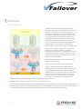
Overview
1.1. Description
vfailover provides an automated failover and
failback mechanism for virtualized data centers in
VMware environments. Mirrored data stores and
raw device mappings can be switched between
sites either in planned or disaster scenarios. Due
to its broad range of supported VMware high
availability cluster configurations it can be easily
integrated in existing environments. vfailover
closes the gap between storage and application
administration by combining deep VMware
knowledge with years of storage array experience.
vfailover is a solution designed for minimizing
downtime in cases of disaster or planned
maintenance operations in a VMware HA-Cluster
environment running in two datacenters. There is
no need to reconfigure the virtual environment
before initiating failovers.
Failover/Failback tasks are fully automated and
initiated the same way.
Replication may be configured bidirectional.
vfailover works on data store / RAW device
mapping basis. That means single, multiple or all
mirrored Datastores can be switched between
datacenters in one task with one click (command).
vfailover is a script based solution running on
vCenter Server or a system which has network
connection to vCenter Server. There slightly
different requirements depending on the supported storage platforms.
vfailover works in environments with one or two vCenter servers.
vCenter is an essential component. It has to be assured that it’s available or can be recovered easily at the
remaining site in case of a disaster. With this solution and storage vendors remote replication technologies
it is possible to protect important virtual machines by mirroring the underlying data stores.
3
Implementation and User Guide
1.2. Environment
vCenter Server: Central Management Server for the virtual infrastructure.
ESX(i) Servers: Hosts with VMware ESX or ESXi Hypervisor, configured into VMware High
Availability Clusters.
HDS Storage Array: HDS enterprise or modular storage arrays with Truecopy replication setup for
datastores.
PowerCLI: VMware scripting interface for virtual infrastructure.
vfailover: Script environment, managing automated failover between sites in the virtual
environment.
1.3. Integration
4
Identify datastores which should be protected between sites
Setup Truecopy replication for datastores which shall be protected
Provide access to Truecopy secondary volumes to all ESX(i) hosts in the VMware high availability
cluster(s)
Install Hitachi Raid Manager software and VMware PowerCLI at the vCenter Server(s) or a
dedicated management host which remains available in case of disaster and has network access to
vCenter server
Present Hitachi Command Devices to either vCenter server(s) or dedicated management host for
vfailover
Setup vfailover parameters - Storage-, vCenter- and Site-setup
Run vfailover configuration
Initiate failover test with non-production datastore
Implementation and User Guide
System Requirements
2.1. VMware Environment
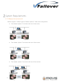
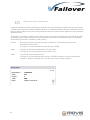
vfailover supports 3 different types of VMware vSphere ™ data center configurations
5
One VMware vSphere ™ HA cluster with one vCenter server
Two VMware vSphere ™ HA clusters with one vCenter server
Two VMware vSphere ™ HA clusters with two vCenter servers
Implementation and User Guide
vCenter server is the core component in the VMware virtual infrastructure. It is essential that it is available
or can be easily restored to running state in case of a site failure. There are several ways (best practice) to
achieve this:
Two virtual center configuration, one at each datacenter
In this setup no extra tasks are necessary to make vCenter accessible on both sites. vfailover can
be integrated on each vCenter server.
Cold Standby vCenter server
vCenter server is setup as virtual machine in the virtual environment. Scheduled clones of the
vCenter VM to a datastore located at the other datacenter ensures that vCenter server is ready to
be booted at the remaining datacenter in case of disaster. The datastore where the VM-Clone
resides should be available to all ESX(i) hosts in the second datacenter. Then the administrator can
decide where to register and startup the “backup vCenter server”. Clones should be created on a
regular basis (once a day) to make sure vCenter configuration is current. The schedule depends
on the configuration changes or monitoring needs for the environment. Two separate vfailover
management hosts, one at each site, have to be used in this configuration, because it is not
possible to establish clones from virtual machines with raw device mapping.
Any other method making vCenter server available
There are other methods, several third party products and VMware vCenter Heartbeat to replicate
vCenter server to a secondary site and make it available in a disaster scenario. As long as vfailover
runs on its own management servers there should be no impact to vfailover operations. Because
of disaster recovery is a complex topic each individual solution should be verified by a consultant
before starting a vfailover implementation.
2.2. VMware Software Requirements
The following VMware software versions are supported:
6
VMware vSphere ™ vCenter 4.0, 4.1, 5.0, 5.1, 5.5
ESX, ESXi 4.0, 4.1, 5.0, 5.1, 5.5
PowerCLI 4.0, 4.1, 5.0, 5.1, 5.5
Implementation and User Guide
2.3. Hitachi Data Systems Storage Arrays
The following HDS storage systems are supported:
Hitachi Thunder 9570V / 9580V
Hitachi AMS 200 / 500 / 1000
Hitachi AMS 2100 / 2300 / 2500
Hitachi TagmaStore Universal Storage Platform 100 / 600 / 1100
Hitachi TagmaStore Network Storage Controller 55
Hitachi Universal Storage Platform V / VM
Hitachi Virtual Storage Platform (IP- and FC based Command Device support) / G1000
Hitachi Unified Platform VM
Hitachi Unified Storage 100 Family (HUS 110, HUS 130, HUS 150)
2.4. Hitachi Data Systems Software Requirements
The following HDS software products are required:
Recent Storage Array Controller Firmware/Software
Hitachi Truecopy synchronous replication
Hitachi Command Control Interface 01-32-03/01 (HUS and AMS) and above, 01-32-03/06 (USP,
USP-V, VSP/G1000, HUS VM) and above
2.5. vfailover Management Server
If running vfailover on the vCenter server, vSphere compatibility matrix has to be checked:
http://www.vmware.com/resources/compatibility/search.php
The following operating systems and additional software is supported by vfailover:
7
Windows 2003 Server R2
Windows 2008 Server, Windows 2008 Server R2, Windows 2012 Server, Windows 2012 R2 Server
Windows Powershell 4.0
Implementation and User Guide
Implementation
3.1. Installation and Preparation
One vCenter server with two dedicated vfailover management Hosts
Preparation of two virtual machines (Software requirements described in chapter 2)
Installation of Windows Powershell software and/or update to v4,
http://www.microsoft.com/en-us/download/details.aspx?id=40855
Installation of PowerCLI software
Download PowerCLI from VMware website and install as described in the installation Guide
http://communities.vmware.com/community/vmtn/vsphere/automationtools/powercli
Installation of VMware vSphere Client
Installing Hitachi Command Control Interface
Presenting of at least one Command Device per Hitachi Storage Array as raw device
mapping to the virtual machines
Copying vfailover Delivery Kit to “C:\Program Files\vfailover”
Two vCenter Servers
The same steps as described in chapter 3.1.1. apply to this configuration. There is no need to prepare
dedicated virtual machines for vfailover, although it would be possible.
Different vCenter Setup
Any other vCenter server configurations have to be verified before starting the installation. vfailover can
be integrated in various scenarios, but some may require additional effort.
8
Implementation and User Guide
3.2. vfailover Configuration
Permissions
To make vfailover working permissions on the vCenter server and on the management hosts are needed.
For the installation and operation of vfailover local administrator rights are required either on the
dedicated management hosts or on the vCenter servers.
Additionally vfailover can only be executed with a user account that has the “datacenter administrator”
role assigned.
VMware PowerCLI Configuration
vfailover is a scripting solution based on Windows Powershell and VMware PowerCLI extension. It can only
be executed in a Windows Powershell Environment.
To allow scripts be executed from within the shell the execution policy has to be set. You may also get a
warning during the installation of PowerCLI. This warning can be ignored and the installation continued.
9
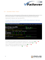
Implementation and User Guide
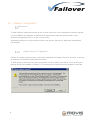
Setting the execution policy can be done after the first run of the PowerCLI Console. There an error
message similar to the screenshot will occur.
Powershell scripts can be signed with digital signatures and per default only signed scripts are allowed to
be executed. Detailed instructions about signing scripts are described in the Windows Powershell
documentation.
vfailover can only be executed on dedicated systems where only authorized administrators with the
necessary permissions have access to. Therefore the vfailover script has no digital signature. To allow the
execution of an unsigned script it is necessary to set the execution policy within the PowerCLI environment
to unrestricted (Run as Administrator if UAC enabled). This can be done with the following commands and
has to be confirmed with “Y”:
Set-ExecutionPolicy unrestricted
Set-ExecutionPolicy bypass
System Environment Variable
To allow vfailover to be installed at any place on the vfailover Management Server please add the
following System Environment variable to your Management Server:
variable = VFAILOVER
value = <Installation Path of vfailover>
f.e. if vfailover is installed at “C:\Program Files\vfailover” set the system environment variable to
VFAILOVER = “C:\Program Files”.
10
Implementation and User Guide
vfailover Cluster Configuration File
vfailover setup is based on configuration files depending on the vSphere environment. Three different
types of vCenter configurations are supported described in chapter 2.1.1.
Configuration is stored in “.properties” files. There are several sections where the operating parameters will
be specified. The configuration Files have to be created in “conf” subfolder in the vfailover directory (e.g.:
“c:\program files\vfailover\conf”) on both vfailover management hosts. This will be done at the initial setup
of vfailover for the existing environment. Every time an additional VMware HA-Cluster is added, new files
have to be created. These files will be created by WebGUI(from version 6.6.3), but you can create it
manually as well.
Global Settings
HorcmRoot = Path where Hitachi Command Controller Interface is installed
Vendor = Storage Vendor ID {HITACHI | HNAS}
SetInvisible = SCSI Hide the S-Vols after Failover {TRUE | FALSE}
SetInvisibleWithConfig = SCSI Hide the S-Vols during Config Run(Backup) {TRUE | FALSE}
HUR = HUR Mirror Unit Number for Horcm Files
ExcludeList = Path to the LDEV Exclude List (RDMs which are not mirrored, One per Line, Decimal)
CTGNO = Consistency Group Number which will be covered with this configuration file
Rescan = HBA Rescan Option {SERIAL | PARALLEL}
RemoveVMHostOnFailure = in case of UNPLANNED Failover choose to remove ESX Hosts with dead
objects (data stores and/or virtual machines) from Config {YES | NO}
ObjectPrefix = Choose Prefix for virtual machine – and data store name on recovered Site during
UNPLANNED failover {e.g.: recovered_by_vfailover_}
VMsInParallel = How many VMs should be registered in parallel, default = 50
Log Level
LogLevel = Specify Logging {1:Error | 2:Warning | 3:Info | 4:Debug}
Datastores(Datastore Clusters)
dsCluster = Datastore Cluster(s) handled by vFailover, comma separated {e.g.: DSCProduction}
dsIdentifier = Datastore(s) handled by vFailover, comma separated {vFailover*}
dsvCenter = Datastore where the vCenter server is located {e.g.: “san_vCenter”}
Email Settings for Mode Status
EmailNotification = Email Notification enabled {NEVER | ONERROR | ALWAYS}
EmailSmtpServer = SMTP Server for sending mail
EmailFrom = Email sender address vFailover should use
EmailTo = Email Recipient(s) address, comma separated
11
Implementation and User Guide
Virtual Machine Boot Order Control
WaitOnPing = vFailover waits on ping before starting next set of VMs {TRUE | FALSE}
PingTimeOut = Seconds to wait for ping reply
Site A(Datacenter A) Configuration Settings
DataCenterA = Data center Identifier
vCenterServerA = vCenter Server Name or IP Address
ConnectionTypeA = vCenter Server connection type: http, https
InstanceA = Instance Number used by Hitachi Command Control Interface
PortA = TCP-Port used by Hitachi Command Controller Interface
StorageA = Storage subsystem serial number
HAClusterA = vSphere HA Cluster
SiteA = ESX(i) hosts in site A, comma separated
Site B(Datacenter B) Configuration Settings
DataCenterB = Data center Identifier
vCenterServerB = vCenter Server Name or IP Address
ConnectionTypeB = vCenter Server connection type: http, https
InstanceB = Instance Number used by Hitachi Command Control Interface
PortB = TCP-Port used by Hitachi Command Controller Interface
StorageB = Storage subsystem serial number
HAClusterB = vSphere HA Cluster
SiteB = ESX(i) hosts in site A, comma separated
12
Implementation and User Guide
Example property file “HDS.properties”:
13
Implementation and User Guide
With some of these parameters the specific vSphere environment will be defined. Here are configuration
examples for the different setups:
one VMware vSphere ™ HA cluster with one vCenter server
HAClusterA=myVMwareCluster
HAClusterB=
vCenterServerA=myVSphereServer
vCenterServerB=
two VMware vSphere ™ HA cluster with one vCenter server
HAClusterA=myVMwareClusterA
HAClusterB=myVMwareClusterB
vCenterServerA=myVSphereServer
vCenterServerB=
two VMware vSphere ™ HA cluster with two vCenter server
HAClusterA=myVMwareClusterA
HAClusterB=myVMwareClusterB
vCenterServerA=myVSphereServerA
vCenterServerB=myVSphereServerB
Configuration files need to be created for each VMware vSphere ™ HA cluster configuration or each
consistency group that builds a unique block out of some data stores and / or raw device mappings.
14
Implementation and User Guide
vfailover Bootorder Configuration
It may be essential to define a specific boot order for the virtual machines to make sure the environment
is working correctly after a failover/failback operation. For example Windows Domain Controllers must be
the first systems which are up and running because most of the other servers depend on Active Directory
Domain services.
Therefore it is necessary to define a boot order for the virtual machine startup process. This will be done
by specifying the Custom Attributes for Virtual Machines that have to boot before others (for example
Active Directory Domain Controllers, LDAP Servers).
vPriority:
Boot Order Priority. Ascending (Lowest number first). VMs with same priority are
processed as they come if.
(If empty or custom attribute not exists vPriority = 9999)
vWait:
Seconds to wait before starting next virtual machine.
(If empty or custom attribute not exists vWait = 60)
vBoot:
Start VM or keep VM powered off
(If empty or custom attribute does not exist, VM will be started if it was running before
failover or will be kept powered off if it was not turned on before failover)
15
Implementation and User Guide
vfailover Configuration File Parameter: CTGNO
vfailover can handle two different types of consistency group usage:
Scenario 1 (“CTGNO” needs not to be defined in configuration file):
Data store 1
o virtual machine 1
virtual disk on data store 1
raw device 1
raw device 2
o virtual machine 2
virtual disk on data store 1
raw device 3
CTGNO = 2
CTGNO = 2 (inherited)
CTGNO = 2
CTGNO = 2
CTGNO = 2 (inherited)
CTGNO = 2
Scenario 2 (“CTGNO” needs to be defined):
Data store 1
o virtual machine 1
virtual disk on data store 1
raw device 1
o virtual machine 2
virtual disk on data store 1
raw device 2
Data store 2
o virtual machine 1
virtual disk on data store 2
o virtual machine 2
virtual disk on data store 2
CTGNO = 5
CTGNO = 5 (inherited)
CTGNO = 5
CTGNO = 5 (inherited)
CTGNO = 5
CTGNO = 5
CTGNO = 5 (inherited)
CTGNO = 5 (inherited)
In scenario 1 there is no need to set the CTGNO parameter as there is only one data store configured in
consistency group 2. Typically you would create one vfailover configuration file per Vmware cluster setup.
In scenario 2 there are two different data stores serving the same virtual machines with capacity. In that
case it makes sense to define consistency group as the virtual machine might need consistency over all
their hard disks in case of a failure. Therefore you need to configure those two data stores into the same
consistency group 5. By specifying “CTGNO=5” within the vfailover configuration file the HORCM
instances will be created with only one group instead of a group per data store. You create as much
vfailover configuration files for the same Vmware cluster as consistency groups exists.
In case of a failover at scenario 1 you can failover data store by data store or all data stores at once.
In case of a failover at scenario 2 you can only failover all data stores together.
16
Implementation and User Guide
vfailover Operation
4.1.User Authentication
User Authentication has changed with version 6.6.2 to a more secure method. User Name and password
had to be specified during execution of vFailover. Credentials were stored if optional parameter “StoreCredentials:$true” was used
Now you have to use “-StoreCredentials:$true” parameter the first time you execute an vfailover operation
for a specific User. Then you will be asked for Username and password. These credentials will be stored
and encrypted. After that you do not need to specify the “-User” or “-password” parameter for this user.
For WebGUI operation you have to have a user with stored credentials, otherwise no Login is possible!!!
4.2. Operation Mode “config”
This mode is essential for a working vfailover environment. Every time LUN configuration changes occur in
the vCenter clusters, vfailover operation mode “config” must be executed. After a failover/failback the
operation mode “config” has to be executed too. For a successful configuration all datastores, which
should be used with vfailover, have to be mirrored between the two sites and mirror state must be “PAIR”
from within Storage Navigator (Modular) or Command Control Interface. If mirror state is different
operation mode “config” may not be able to detect the exact datastore to LUN mapping and Truecopy
configuration.
To keep vfailover configuration up to date a scheduled run of vfailover operation mode “config” at regular
basis is recommended. This can be done with the Windows Scheduler or any other task scheduling tool
on the host(s) vfailover is installed.
Sample syntax for operation mode “config”, before 6.6.2:
C:\Program Files\vfailover\Scripts\vfailover.ps1 -ConfFile "vfailover_MainCluster" -User
Administrator -Mode config
Sample syntax for operation mode “config”, after 6.6.2:
C:\Program Files\vfailover\Scripts\vfailover.ps1 -ConfFile "vfailover_MainCluster" -Mode config –
StoreCredentials:$true
You then will be asked for user name and password.
17
Implementation and User Guide
After that you can run any vFailover command without credentials within this user context!
C:\Program Files\vfailover\Scripts\vfailover.ps1 -ConfFile "vfailover_MainCluster" -Mode config
In this case the configuration file “vfailover_MainCluster.properties” will be used for the vCenter setup
parameters. vfailover database configuration will be done for all Datastores which are specified in
the .properties File with the parameter “dsCluster” or “dsIdentifier”. If a “*” is specified for the parameter “dsIdentifier” all datastores will be stored in the vfailover database (settings specified in the .properties File
can be overruled if parameter “Datastore” is used in the COMMAND prompt during execution). For the
connection to the vCenter server the vCenter user “administrator” will be used. After executing this
operation mode a password prompt appears in the PowerCLI window.
18
Implementation and User Guide
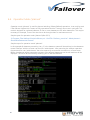
4.3. Operation Mode “status”
Operation mode “status” displays the state of vFailover setup and configuration backup and the according
state of the Truecopy mirror. In a working vSphere environment this information can be used for
documentation purposes or to check if all Truecopy mirrors are working and in the proper state.
Sample syntax for operation mode “status”(after v6.6.2):
C:\Program Files\vfailover\Scripts\vfailover.ps1 -ConfFile "vfailover_MainCluster" -Mode status
Sample output for operation mode “status”:
“xml”: Backup of all Configuration Settings(Cluster, Datastore, VM, …) was successful (0) or not (X)
“vm host”: all VM Hosts(ESXi Servers) specified in .porperties File are available (0) or not (X)
“horcm”: HORCM Files are available and Instances are running (0) or not (X)
“replication”: Truecopy Replication Status is OK (0) or not OK (X)
19
Implementation and User Guide
4.4. Operation Mode “planned”
Operation mode “planned” is used for planned switching (failover/failback) operations. It can only be used
if the affected vSphere HA-Clusters are fully operational and the Truecopy mirrors are in pair state. This
mode is designed for a planned takeover of one or more datastores to the other datacenter. This may be
necessary for example, if one of the sites has to be brought down for maintenance work.
Sample syntax for operation mode “planned”(after 6.6.2):
C:\Program Files\vfailover\Scripts\vfailover.ps1 -ConfFile "vfailover_movis-ha" -Mode planned –
DestinationDatacenter Remote
Sample output for operation mode “planned”:
In this example all datastores containing “san_vf” in the datastore name will be switched to the datacenter
named “Remote” with the vCenter user account “administrator”. After executing the vfailover operation
the password for user “administrator” has to be entered for a successful connection to vCenter server.
Before the takeover will be executed a summary of the affected datastores and virtual machines will be
displayed. This has to be confirmed by entering “yes” to start the takeover.
20
Implementation and User Guide
Workflow major steps for a planned failover operation:
21
Shutdown/PowerOff virtual machines - all virtual machines where VMware Tools are installed will
be shut down properly. If not possible or no VMware Tools are available they will be powered off.
The script waits 5 minutes initially on the shut down process. If some of the virtual machines do
not shut down within the first 5 minutes user will be asked whether to wait another 5 minutes, to
wait forever or to force a power off (Possible User Input: wait5min, forever, poweroff).
Reconfigure virtual machines for failover – Raw Device Mappings and virtual disks which reside on
a different datastore than the main datastore of the virtual machine have to be removed from
virtual machine configuration for a proper takeover.
Attention! If virtual disks reside on different datastores user has to failover all the datastores
together in one step.
Unregister virtual machines – Virtual Machines will be unregistered from vCenter configuration.
Unmount data store(s) from all ESX(i) hosts if vSphere Version 5 is installed.
Swap storage replication (horctakeover) of datastore and RAW Device LUNs at Storage level –
Truecopy mirrors volumes will be failovered.
Rescan HBAs and VMFS – Rescan of all ESX(i) hosts to refresh vCenter LUN configuration.
Resignature datastores – Datastores may be recognized as Snapshots at the other site. As the
base signature values have changed (other storage subsystem) resignature will be executed to
write a new signature onto the datastore. This operation involves another vmfs rescan.
Rescan HBAs and VMFS – Rescan of all ESX(i) hosts to refresh vCenter LUN configuration.
Register virtual machines – Virtual Machines will be re-registered in the vCenter.
Reconfigure virtual machines:
o
Raw Device Mappings and virtual disks will be added back to the Virtual Machine
configuration.
o
Move virtual machines into “its” folder
o
Set custom attributes
o
Reconfigure virtual distributed network switch configuration
Reconfigure cluster to rebuild all the virtual machine settings that have been before failover.
Power on virtual machines (as defined in bootorder File)
Implementation and User Guide
4.5. Operation Mode “unplanned”
Operation mode “unplanned” should only be used in case of a site/ESX(i) host/storage array failure. With
this mode failed datastores and virtual machines will be brought online at the remaining site.
Sample syntax for operation mode “unplanned”(after v6.6.2):
C:\Program Files\vfailover\Scripts\vfailover.ps1 -ConfFile "vfailover_movis-ha -Mode unplanned –
DestinationDatacenter Remote
In this example all datastores containing “san_vf” in the datastore name will be switched to the datacenter
named “Remote” with the vCenter user account “administrator”. After executing the vfailover operation
the password for user “administrator” has to be entered for a successful connection to vCenter server.
Before the takeover will be executed a summary of the affected datastores and virtual machines will be
displayed. This has to be confirmed by entering “yes” to start the takeover.
22
Implementation and User Guide
Workflow major steps for an unplanned failover operation:
23
Move still running virtual machines – VMs have to be moved from VM Hosts that also run virtual
machines with failed datastores (Storage Subsystem failure)
If Parameter “RemoveVMHostOnFailure is set to “Yes” VM Hosts and/or VM Hosts with failed
datastores will be disconnected and removed– VM Hosts with orphaned objects have to be
removed from vCenter configuration for proper failover operation. If Parameter
“RemoveVMHostOnFailure is set to “No” VM Hosts and VMs will remain in configuration as
orphaned objects. Mirrored Datastores and depending VMs will be recovered and get a prefix as
defined with the “ObjectPrefix” parameter in the config file. VCenter configuration has to be
cleaned up manually (delete orphaned objects) after unplanned failover operation.
Based on user input storage will be treated as available or not availabe.
Available: Swap storage replication (horctakeover) of datastore and RAW Device LUNs at Storage
level – Truecopy mirrors volumes will be failovered (Like in planned mode).
Not available: Make replication volumes read- and writeable on second storage subsystem –
Enable write access to LUNs at the remaining datastore, remove write access from primary
volumes if still available
Rescan HBAs and VMFS – Rescan of all ESX(i) hosts to refresh vCenter LUN configuration.
Resignature datastores – Datastores may be recognized as Snapshots at the other site. As the
base signature values have changed (other storage subsystem) resignature will be executed to
write a new signature onto the datastore. This operation involves another vmfs rescan.
Rescan HBAs and VMFS – Rescan of all ESX(i) hosts to refresh vCenter LUN configuration.
Register virtual machines – Virtual Machines will be re-registered in the vCenter.
Reconfigure virtual machines:
o
Raw Device Mappings and virtual disks will be added back to the Virtual Machine
configuration.
o
Move virtual machines into “its” folder
o
Set custom attributes
o
Reconfigure virtual distributed network switch configuration
Reconfigure cluster to rebuild all the virtual machine settings that have been before failover.
User can decide if the script should power on the virtual machines (based on their previous state
or as defined in the BootOrder File) or if the virtual machines should stay powered off.
Implementation and User Guide
4.6. Operation Mode “repair”
Operation mode “repair” checks all the Virtual Machines in a cluster after an unplanned failover for
custom attributes, resource pool association, folder association and dvSwitch configuration. If there are
any paramters missing they will be reconfigured.
ATTENTION: You must have valid configuration files (Folder ..\vfailover\db) from the point of time before
the unplanned failover was done. Do not run the script with mode “config” after an unplanned failover if
you want to use the “repair” mode.
Sample syntax for operation mode “repair”(after v6.6.2):
C:\Program Files\vfailover\Scripts\Failover.ps1 -ConfFile "maincluster" -Mode repair
Sample output for operation mode “repair”:
Mode “repair” creates a list of all VMs and reconfigures the VM parameters.
24
Implementation and User Guide
4.7. Operation Mode “vcenter”
Operation Mode “vcenter” can only be used if virtual center server is a virtual machine which resides on a
mirrored datastore (Only and all vcenter related VMs should be on that datastore, e.g. server where
vcenter db is installed, if not the same machine).
Operation mode “vcenter” can be used in case of a site/ESX(i) host/storage array failure or in case of a
planned failover. With this mode failed datastores and virtual machines will be brought online at the
remaining site.
In this mode you need to specify a user account which has root permission on one of the remaining ESX(i)
hosts. Because in case of no virtual center server is available, switching tasks have to be done on one of
the ESX(i) hosts.
Sample syntax for operation mode “unplanned”:
C:\Program Files\vfailover\Scripts\vfailover.ps1 -ConfFile "vfailover_Maincluster" -User root -Mode
vcenter –DestinationDatacenter Remote -Datastore vcenter
In this example the Datastore called vcenter will be switched to the remaining or remote Datacenter. All
other systems won’t be affected. After executing the vfailover operation the password for user “root” has
to be entered for a successful connection to an ESX(i) server. Before the takeover will be executed you
have to choose the ESX(i) host and answer a few questions. Then a summary of the affected datastores
and virtual machines will be displayed. This has to be confirmed by entering “yes” to start the takeover.
Workflow major steps for an unplanned failover operation:
25
Connect to ESX(i) server
Find out the virtual machine where vcenter server is installed
Based on user input storage will be treated as available or not availabe.
Available: Swap storage replication (horctakeover) of datastore LUNs at Storage level – Truecopy
mirrors volumes will be failovered
Not available: Make replication volumes read- and writeable on second storage subsystem –
Enable write access to LUNs at the remaining datastore, remove write access from primary
volumes if still available
Rescan HBAs and VMFS – Rescan ESX(i) host to refresh vCenter LUN configuration.
Resignature datastore – Datastore may be recognized as Snapshots at the other site. As the base
signature values have changed (other storage subsystem) resignature will be executed to write a
new signature onto the datastore. This operation involves another vmfs rescan.
Rescan HBAs and VMFS – Rescan ESX(i) host to refresh vCenter LUN configuration.
Register virtual machine – Virtual Machine will be registered on ESX(i) host
User can decide if the script should power on the virtual machine
Implementation and User Guide
vfailover Framework
vfailover uses a designated Folder structure. This structure is already preconfigured in the vfailover
delivery kit and should be copied to "%ProgramFiles%" folder on the vfailover management host(s) or
vCenter server(s).
Folder Structure:
26
Backup – Folder not actively used by vfailover. Could be used to store xml File exports from “db”
folder.
Conf – vfailover Cluster Configuration files created during initial setup or if new clusters are added
Db – xml Files with backup of the vCenter configuration. Created during operation mode “config”
if parameter “backup” is specified.
Log – Log file folder for all vfailover operations
Scripts – vfailover Powershell script folder
Tmp – Folder for temporary files created during vfailover operations
Web – Folder for vFailover WebGUI
Implementation and User Guide
Parameter
Name
Type
Decription
ConfFile
User
string
string
Mode
string
Name of configuration file
User that has the proper privileges to connect to the VMware vCenter Server –
Obsolete from v6.5 on, use StoreCredentials instead
planned – planned Failover
unplanned – unplanned Failover
status – Status View
config – update vfailover DB
repair – Repairs Virtual Machine configuration
vcenter – failover mirrored Datastore with vCenter server on it
Default: config
Datastore Identifier(if not specified in .properties file or entries in .properties
file should be overruled)
Datastore
string
DestinationDataCenter
string
Default: * (all)
Is an option when executing with mode “planned” or “unplanned”
boolean
Data center to which the script should failover the data stores and virtual
machines
Is an option when executing with mode “config”.
Backup
Stores information in the db folder of vfailover that allowes unplanned failover
StoreCredentials
boolean
Default: true
Is a mandatory option when using WebGUI!!!!! Executing with all modes.
Usage example:
vfailover.ps1 -conffile hitachi -mode status -storecredentials:$true
--> you will be asked for “vcenter" and “storage” user, credentials will be stored
for this user(128bit encryption)
After that you can run vFailover without Parameter “-User"
vfailover.ps1 -conffile hitachi -mode config/status/planned etc... --> without “user”
With WebGUI you need a User with stored Credentials!!! No other user can
modify the credentials, only the user itself!!
Default: false
27
Implementation and User Guide
Name
Type
Decription
MaintenanceMode
boolean
Is an option when executing with mode “planned”
If for example all the datastores should be switched from SiteA to SiteB for
maintenance reasons and this option is set to “$true”, all the ESX(i) hosts at
SiteA will be brought into maintenance mode.
SilentMode
boolean
Default: false
Is an option when executing with mode “planned”
No interaction with user at all. In case of a failure the script retries each
function 5 times before configuring automatic failback.
ConsoleOutput
string
Default: false
If a filename is specified for this parameter the console output will also be piped
to the respective file.
RESERVED PARAMETERS:
Name
Type
Decription
SessionId
string
RESERVED FOR WebGUI
PluginRequest
string
RESERVED FOR WebGUI
vCenterRecoveryServer
string
RESERVED FOR vCenter Mode
RecoveryUserPwd
string
RESERVED FOR vCenter Mode
28
Implementation and User Guide
vFailover WebGUI
vFaiover WebGUI is designed to support the administrators using vFailover in their environments.
If a GUI is preferred, all the modes can be executed through the Web Browser. Even configuration settings
can be done there. There is all the Information(Cluster, Host, VMs, Datastores, Disks, …) displayed which is
necessary for operating vFailover.
The WebGUI has to be installed on both management servers!
Requirements for the WebGUI(per Management Server):
Apache Tomcat 7.0.47 for Windows
X64 Java JRE 7 (latest Update)
Web Browser Firefox (working with others too, but vFailover WebGUI is optimized for Firefox)
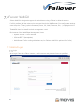
7.1. WebGUI Login
Login
At the Login Frame the vFailover instance, a valid username and password has to be specified.
29
Implementation and User Guide
Instances
Additionally a new instance (.properties file) may be created in the login window. An existing instance may
be edited after login with button “Edit” at the top.. These settings will then be saved to the vFailover “Conf”
folder. All necessary parameters are shown in the WebGUI and may be filled out if used.
30
Implementation and User Guide
7.2. WebGUI Overview
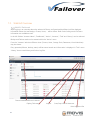
WebGUI Dashboard
After logging in an overview about the selected vFailover configuration(MovisDemo) will be displayed.
Information about the Last Backup, Clusters, Hosts, … will be shown. Boot Order Settings and VM Status
Information are available as well.
In the left Sidebar “Instance Name”, “Dashboard”, “Action”, “Instance”, “Task” and “History” can be selected.
Backup and Failover tasks can be started within the “Action” menu.
From the “Instance” selection different views (Clusters, Hosts, Storage Pods, Datastores, Virtual Machines)
may be chosen.
Every operation(failover, backup, status) will be started as task and information is displayed in “Task” menu.
“History” shows a task history and links to log files.
.
Choose between different Instances
Display Fullscreen
LogOut
Start/Stop HORCM Instances
Hide Left Menu Bar
31
Implementation and User Guide
WebGUI Clusters View
After the Cluster is chosen, information about Datastore, LDEV and replication information will be shown.
If Virtual Machines button will be clicked, information about the virtual machines running within that
cluster will be shown.
32
Implementation and User Guide
WebGUI Hosts View
After one of the VM Hosts(ESXi Server) is chosen, information about Datastore, LDEV and replication
information will be shown. If Virtual Machines button will be clicked in the HostSystem Frame, information
about the virtual machines running on that host will be shown.
33
Implementation and User Guide
WebGUI Storage Pods View
Information about Datastore Clusters(Storage Pods) will be shown there. The member datastores, their
extents, LDEV and Replication Status will be shown. If Virtual Machines button will be clicked in the
StoragePod Frame, information about the virtual machines running on that Storage Pod will be shown.
34
Implementation and User Guide
WebGUI Datastores View
Information about Datastores will be shown there. The extents, StoragePods, LDEV and Replication Status
will be shown. If Virtual Machines button will be clicked in the Datastore Frame, information about the
virtual machines running on that datastore will be shown.
35
Implementation and User Guide
WebGUI Virtual Machines View
Information about Virtual Machines will be shown there. This information will be fetched from vCenter
Server. You can see utilization of disk space, memory and cpu.
The replication state is displayed and if there is an actual backup.
In the “Datastores” menu more detailed information from the underlying datastore will be displayed.
36
Implementation and User Guide
7.3. WebGUI Actions
WebGUI Backup
WebGUI Backup means that a configuration run of vFailover will be initiated, to get all the actual
configuration information. With “Start”, Backup (=config run) may be initiated immediately.
Additionally a scheduled task (“Task Scheduler” Menu) can be created in the Windows Task Scheduler for
the configuration run. Then it will be assured that configuration information will be updated in a regular
basis. These scheduled Tasks can only be created, but have to be deleted manually from within the
Windows Task Scheduler!!
37
Implementation and User Guide
WebGUI Planned Failover
Planned Failover can be initiated through the WebGUI. Either an “Maintenance Activity (planned)” or an
“Disaster Recovery (Unplanned)” can be initiated.
First select the Datacenter and the active datastores are shown which may be switched to the other
datacenter.All datastores which are selected will be switched to the other site after “Start” button is
pressed.
38
Implementation and User Guide
After vFailover initialization has finished, the failover task has to be confirmed by pressing the “yes” button.
If Browser will be accidentally closed, it can be started again and the ongoing task status will be displayed!
39
Implementation and User Guide
WebGUI UnPlanned Failover
Unplanned Failover can be initiated through the WebGUI. Select “Disaster Recovery (Unplanned)”.
First datacenter has to be selected, then active datastores will be displayed. Choose all datastores that
should be switched. Then Start Button has to be pressed.
40
Implementation and User Guide
After vFailover initialization has finished, some questions have to be answered. Depending on the failed
components. Please follow the questions on screen and answer them correctly with (yes/no/dontknow).
41
Implementation and User Guide
Then type yes again to proceed and initiate the failover!!!
42
Implementation and User Guide
WebGUI Recover vCenter
On the Login page login to one of the ESXi hosts on the remaining site which is still running and has
access to the datastore mirror(S-Vol) where vCenter server is stored. Make sure that you have root
permissions to the ESXi host.
That is used for bringing a vCenter Server and all the VMs at the same datastore online on the remaining
site after an unplanned outage!! This is possible if the vCenter Server and its database server are on the
same datastore which is mirrored with Truecopy or HUR!!!
43
Implementation and User Guide
Press Start to recover vCenter server.
After that the datastore will be brought online on the remaining site, the vCenter server will be brought
online. As soon as vCenter is up and running an unplanned failover operation, for all the other protected
VMs in the environment, can be started.
44
Implementation and User Guide
For the failover/recovery of vCenter server some questions have to answered.
45
Implementation and User Guide
46
Implementation and User Guide
WebGUI History
History shows task list and link to logfiles for troubleshooting.
47
Implementation and User Guide
vSphere Settings
In vSphere 5 environments an additional parameter is mandatory for Setups with only one vCenter Servers.
If access to Storage is lost in VMware this scenario is called APD(All Path Down). In this case the VM Hosts
(ESXi Server) try to get the paths back online again. This may result in a condition where all affected ESX
Hosts (even on remaining site) and VMs will get unresponsive, which in some circumstances causes the
whole virtual environment to fail!!!!
To avoid this behavior a parameter has to be changed on the ESX Hosts. This parameter tells the ESX
Hosts to fail unresponsive LUNs when all paths are gone (Storage outage).
Value for “VMFS3.FailVolumeOpenIfAPD” has to be set to 1:
48