1
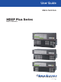
User Guide
Matrix Switchers
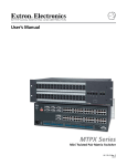
HDXP Plus Series
Matrix Switchers
68-1200-01 Rev. B
10 13
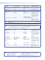
Safety Instructions
Safety Instructions • English
WARNING: This symbol,
, when used on the product, is intended to
alert the user of the presence of uninsulated dangerous voltage within the
product’s enclosure that may present a risk of electric shock.
ATTENTION: This symbol,
, when used on the product, is intended
to alert the user of important operating and maintenance (servicing)
instructions in the literature provided with the equipment.
For information on safety guidelines, regulatory compliances, EMI/EMF
compatibility, accessibility, and related topics, see the Extron Safety and
Regulatory Compliance Guide, part number 68-290-01, on the Extron website,
www.extron.com.
Instructions de sécurité • Français
AVERTISSEMENT : Ce pictogramme,
, lorsqu’il est utilisé sur le
produit, signale à l’utilisateur la présence à l’intérieur du boîtier du produit
d’une tension électrique dangereuse susceptible de provoquer un choc
électrique.
ATTENTION :Ce pictogramme,
, lorsqu’il est utilisé sur le produit,
signale à l’utilisateur des instructions d’utilisation ou de maintenance
importantes qui se trouvent dans la documentation fournie avec le
matériel.
Pour en savoir plus sur les règles de sécurité, la conformité à la réglementation,
la compatibilité EMI/EMF, l’accessibilité, et autres sujets connexes, lisez les
informations de sécurité et de conformité Extron, réf. 68-290-01, sur le site
Extron, www.extron.fr.
Sicherheitsanweisungen • Deutsch
WARNUNG: Dieses Symbol
auf dem Produkt soll den Benutzer
darauf aufmerksam machen, dass im Inneren des Gehäuses dieses
Produktes gefährliche Spannungen herrschen, die nicht isoliert sind
und die einen elektrischen Schlag verursachen können.
VORSICHT: Dieses Symbol
auf dem Produkt soll dem Benutzer in der
im Lieferumfang enthaltenen Dokumentation besonders wichtige Hinweise
zur Bedienung und Wartung (Instandhaltung) geben.
Weitere Informationen über die Sicherheitsrichtlinien, Produkthandhabung,
EMI/EMF-Kompatibilität, Zugänglichkeit und verwandte Themen finden Sie in
den Extron-Richtlinien für Sicherheit und Handhabung (Artikelnummer
68-290-01) auf der Extron-Website, www.extron.de.
Instrucciones de seguridad • Español
ADVERTENCIA: Este símbolo,
, cuando se utiliza en el producto,
avisa al usuario de la presencia de voltaje peligroso sin aislar dentro del
producto, lo que puede representar un riesgo de descarga eléctrica.
ATENCIÓN: Este símbolo,
, cuando se utiliza en el producto, avisa
al usuario de la presencia de importantes instrucciones de uso y
mantenimiento recogidas en la documentación proporcionada con el
equipo.
Para obtener información sobre directrices de seguridad, cumplimiento
de normativas, compatibilidad electromagnética, accesibilidad y temas
relacionados, consulte la Guía de cumplimiento de normativas y seguridad de
Extron, referencia 68-290-01, en el sitio Web de Extron, www.extron.es.
Инструкция по технике безопасности • Русский
ПРЕДУПРЕЖДЕНИЕ: Данный символ,
, если указан
на продукте, предупреждает пользователя о наличии
неизолированного опасного напряжения внутри корпуса
продукта, которое может привести к поражению
электрическим током.
ВНИМАНИЕ: Данный символ,
, если указан на продукте,
предупреждает пользователя о наличии важных инструкций
по эксплуатации и обслуживанию в руководстве,
прилагаемом к данному оборудованию.
Для получения информации о правилах техники безопасности,
соблюдении нормативных требований, электромагнитной
совместимости (ЭМП/ЭДС), возможности доступа и других
вопросах см. руководство по безопасности и соблюдению
нормативных требований Extron на сайте Extron: www.extron.ru,
номер по каталогу - 68-290-01.
Chinese Simplified(简体中文)
警告:
产品上的这个标志意在警告用户该产品机壳内有暴露的危险 电压,
有触电危险。
注 意:
产 品 上 的 这个 标 志 意 在 提 示用 户 设 备 随 附 的 用 户 手 册 中 有
重要的操作和维护(维修)说明。
关于我们产品的安全指南、遵循的规范、EMI/EMF 的兼容性、无障碍
使用的特性等相关内容,敬请访问 Extron 网站 www.extron.cn,参见 Extron
安全规范指南,产品编号 68-290-01。
Chinese Traditional(
)
警告:
若產品上使用此符號,是為了提醒使用者,產品機殼內存在著
可能會導致觸電之風險的未絕緣危險電壓。
注意
若產品上使用此符號,是為了提醒使用者。
有關安全性指導方針、法規遵守、EMI/EMF 相容性、存取範圍和相關主題的詳
細資訊,請瀏覽 Extron 網站:www.extron.cn,然後參閱《Extron 安全性與法
規遵守手冊》,準則編號 68-290-01。
Japanese
警告: この記号
が製品上に表示されている場合は、筐体内に絶縁されて
いない高電圧が流れ、感電の危険があることを示しています。
注意: この記号
が製品上に表示されている場合は、本機の取扱説明書
に 記載されている重要な操作と保守(整備)の指示についてユーザーの 注
意を喚起するものです。
安全上のご注意、法規厳守、EMI/EMF適合性、その他の関連項目に
ついては、エクストロンのウェブサイト www.extron.jp より『Extron Safety and
Regulatory Compliance Guide』(P/N 68-290-01) をご覧ください。
Korean
경고: 이 기호
가 제품에 사용될 경우, 제품의 인클로저 내에 있는
접지되지 않은 위험한 전류로 인해 사용자가 감전될 위험이 있음을
경고합니다.
주의: 이 기호
가 제품에 사용될 경우, 장비와 함께 제공된 책자에 나와
있는 주요 운영 및 유지보수(정비) 지침을 경고합니다.
안전 가이드라인, 규제 준수, EMI/EMF 호환성, 접근성, 그리고 관련 항목에
대한 자세한 내용은 Extron 웹 사이트(www.extron.co.kr)의 Extron 안전 및
규제 준수 안내서, 68-290-01 조항을 참조하십시오.
FCC Class A Notice
This equipment has been tested and found to comply with the limits for a Class A digital device,
pursuant to part 15 of the FCC rules. The Class A limits provide reasonable protection against harmful
interference when the equipment is operated in a commercial environment. This equipment generates,
uses, and can radiate radio frequency energy and, if not installed and used in accordance with the
instruction manual, may cause harmful interference to radio communications. Operation of this
equipment in a residential area is likely to cause interference; the user must correct the interference at
his own expense.
NOTE: For more information on safety guidelines, regulatory compliances, EMI/EMF compatibility,
accessibility, and related topics, see the “Extron Safety and Regulatory Compliance
Guide” on the Extron website.
Copyright
© 2013 Extron Electronics. All rights reserved.
Trademarks
All trademarks mentioned in this guide are the properties of their respective owners.
The following registered trademarks®, registered service marks(SM), and trademarks(TM) are the property of
RGB Systems, Inc. or Extron Electronics:
Registered Trademarks (®)
AVTrac, Cable Cubby, CrossPoint, eBUS, EDID Manager, EDID Minder, Extron, Flat Field, GlobalViewer, Hideaway, Inline, IP Intercom, IP Link,
Key Minder, LockIt, MediaLink, PlenumVault, PoleVault, PowerCage, PURE3, Quantum, SoundField, SpeedMount, SpeedSwitch, System
Integrator, TeamWork, TouchLink, V‑Lock, VersaTools, VN‑Matrix, VoiceLift, WallVault, WindoWall, XTP and XTP Systems
Registered Service Mark(SM) : S3 Service Support Solutions
Trademarks (™)
AAP, AFL (Accu‑Rate Frame Lock), ADSP (Advanced Digital Sync Processing), AIS (Advanced Instruction Set), Auto‑Image, CDRS (Class D
Ripple Suppression), DDSP (Digital Display Sync Processing), DMI (Dynamic Motion Interpolation), Driver Configurator, DSP Configurator, DSVP
(Digital Sync Validation Processing), FastBite, FOXBOX, IP Intercom HelpDesk, MAAP, MicroDigital, ProDSP, QS-FPC (QuickSwitch Front Panel
Controller), Scope‑Trigger, SIS, Simple Instruction Set, Skew‑Free, SpeedNav, Triple‑Action Switching, XTRA, ZipCaddy, ZipClip
Conventions Used in this Guide
Notifications
The following notifications are used in this guide:
WARNING: A warning indicates a situation that has the potential to result in death or
severe injury.
ATTENTION: Attention indicates a situation that may damage or destroy the product or
associated equipment.
NOTE: A note draws attention to important information.
TIP: A tip provides a suggestion to make working with the application easier.
Software Commands
Commands are written in the fonts shown here:
^AR Merge Scene,,Op1 scene 1,1 ^B 51 ^W^C
[01] R 0004 00300 00400 00800 00600 [02] 35 [17] [03]
E X! *X1&* X2)* X2#* X2! CE}
NOTE: For commands and examples of computer or device responses mentioned
in this guide, the character “0” is used for the number zero and “O” is the capital
letter “o.”
Computer responses and directory paths that do not have variables are written in the font
shown here:
Reply from 208.132.180.48: bytes=32 times=2ms TTL=32
C:\Program Files\Extron
Variables are written in slanted form as shown here:
ping xxx.xxx.xxx.xxx —t
SOH R Data STX Command ETB ETX
Selectable items, such as menu names, menu options, buttons, tabs, and field names are
written in the font shown here:
From the File menu, select New.
Click the OK button.
Specifications Availability
Product specifications are available on the Extron website, www.extron.com.
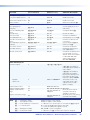
Contents
Introduction.................................................... 1
About this Guide.................................................. 1
About the HDXP Plus Series Matrix Switchers..... 1
Features.............................................................. 2
Application Diagrams........................................... 5
Installation...................................................... 6
Rear Panels and Cabling..................................... 6
Connections........................................................ 7
Video Connections.......................................... 7
External Sync Connections (HDXP 3232
only)............................................................... 8
Reset Button................................................... 9
Ethernet Connection...................................... 10
RS-232 and RS-422 Remote
Connections................................................. 11
Power............................................................ 12
Operation...................................................... 13
Front Panel Controls and Indicators................... 13
Definitions...................................................... 13
Input and Output Buttons.............................. 14
Configuration Port (HDXP 3232 Only)............ 15
Control Buttons............................................. 15
I/O Buttons.................................................... 16
Operations........................................................ 17
Powering On................................................. 17
Creating a Configuration................................ 17
Previewing an Input....................................... 23
Viewing the Configuration.............................. 24
I/O Grouping.................................................. 26
Saving and Recalling Presets......................... 29
Muting and Unmuting Outputs....................... 33
Locking the Front Panel (Executive Mode)..... 35
Setting the Button Background
Illumination................................................... 35
Selecting the RS-232 or RS-422 Protocol
and Baud Rate............................................. 36
Resetting....................................................... 37
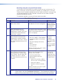
Troubleshooting................................................. 40
Configuration Worksheets................................. 41
Worksheet Example 1: System
Equipment.................................................... 41
Worksheet Example 2: Daily Configuration..... 42
Worksheet Example 3: Test Configuration...... 43
Remote Configuration and Control............ 45
Serial Ports........................................................ 45
Ethernet Port..................................................... 46
Ethernet Cable............................................... 46
Default IP Addresses..................................... 46
Establishing an Ethernet Connection............. 46
Number of Connections................................. 47
Verbose Mode............................................... 47
Host-to-Switcher Instructions............................ 47
Switcher-Initiated Messages.............................. 47
Switcher Error Responses................................. 48
Using the Command and Response Table
for SIS Commands........................................... 49
Symbol Definitions......................................... 49
Command and Response Table for SIS
Commands...................................................... 54
HDXP Plus Series Switchers • Contents
v
Matrix Software............................................ 67
Reference Information.............................. 112
Matrix Switchers Control Program..................... 67
Downloading the Matrix Software Control
Program....................................................... 67
Software Operation Via Ethernet.................... 69
Special Characters........................................ 69
Using the Software........................................ 70
Setting up the Matrix window........................ 73
Managing Ties............................................... 74
IP Setup........................................................ 75
Updating the Firmware.................................. 81
Uploading HTML Files.................................... 83
Windows Buttons, Menus, and Trash Can..... 84
Windows Menus............................................ 84
Using Emulation Mode................................... 89
Using the Matrix Switcher Help System......... 91
Creating Button Labels...................................... 92
Button Icons.................................................. 92
Using the Button Label Generator.................. 92
Replacing Button Labels................................ 94
Blank Button Labels...................................... 95
Mounting the Switcher..................................... 112
Setting an IP Address...................................... 113
What is an IP Address?............................... 113
Choosing IP Addresses............................... 113
Subnet Mask............................................... 114
Pinging for the IP Address........................... 114
Connecting as a Telnet Client....................... 115
Subnetting, a Primer.................................... 117
HTML Configuration and Control............... 96
Accessing the Web Pages................................. 96
Special Characters........................................ 97
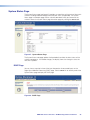
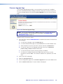
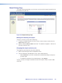
System Status Page.......................................... 98
DSVP Page................................................... 98
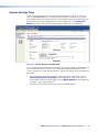
System Settings Page....................................... 99
IP Settings Fields......................................... 100
Date/Time Settings Fields............................ 101
Passwords Page......................................... 102
Email Settings Page..................................... 103
Firmware Upgrade Page.............................. 105
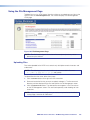
Using the File Management Page.................... 107
Uploading Files............................................ 107
Adding a Directory....................................... 108
Other File Management Activities................. 108
Set and View Ties Page................................... 109
Creating a Tie.............................................. 109
Output Settings Page.................................. 110
Global Presets Page.................................... 111
HDXP Plus Series Switchers • Contents
vi
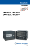
Introduction
This section gives an overview of the Extron HDXP Plus Series Matrix Switchers,
describes significant features of the series, and provides application diagrams.
•
About this Guide
•
About the HDXP Plus Series Matrix Switchers
•
Features
•
Application Diagrams
About this Guide
This user guide contains installation, configuration, and operating information for the
HDXP matrix switchers, including the HDXP 1616, HDXP 3216, and HDXP 3232 models.
The terms “HDXP,” “switcher,” and “HDXP switcher” are used in this guide to refer to all
three HDXP models.
About the HDXP Plus Series Matrix Switchers
The Extron HDXP Plus Series are multi-rate digital matrix switchers that distribute any
serial digital interface (SDI) or high definition serial digital interface (HD-SDI) input to any
combination of SDI and HD-SDI outputs. The HDXP matrix switchers can route multiple
input and output configurations simultaneously. They can route all SMPTE and ITU
standard serial digital video signals up to 2.97 gigabits per second (Gbps), including
dual-link HD-SDI digital video signals and high resolution signals from computer-video
graphics cards equipped with HD-SDI outputs. Three matrix sizes are available:
•
HDXP 1616 (16 inputs by 17 outputs)
•
HDXP 3216 (32 inputs by 17 outputs)
•
HDXP 3232 (32 inputs by 33 outputs)
The HDXP inputs can equalize incoming signals on up to 330 feet (100 meters) of
high-quality cable, such as the Extron RG-6 Super High Resolution (SHR) coaxial cable.
The outputs can reclock and drive all digital signals up to 330 feet (100 meters) on RG-6
cable.
The HDXP Plus series switchers conform to SMPTE and ITU-R BT specifications and
support data rates of 19 megabits per second (Mbps) through 1.485 Gbps.
The zero-skew design of the HDXP ensures that dual-link HD-SDI signals are switched
with no timing errors. The inputs adapt to the incoming signal rate, while the output is
reclocked to the rate of the signal routed to it. The output reclocking can be disabled on
a per-output basis (in bypass mode), or it can be set to a fixed rate. For each input, the
HDXP can report if a signal is available or missing; and for each output, it can report the
signal frequency.
Inputs and outputs can be grouped together to form up to four functional sub-switchers,
based on data rate, video format, location, and so on. This facilitates installation and front
panel control.
HDXP Plus Series Switchers • Introduction
1
The HDXP can operate in two switching modes, selectable via front panel buttons:
•
Matrix switching mode (mode 1): Any input may be switched to any output.
•
Preview selection mode (mode 2): Any single input may be selected and
previewed.
Each HDXP switcher has the rear panel Remote RS232/RS422 port, the front panel
Config RS-232 port, and the LAN port for remote control and configuration. The switcher
can be controlled via the front panel, the Extron Simple Instruction Set (SIS) commands,
the HDXP web pages, and the Extron Windows-based control software via the RS-232 or
RS-422 link, or an Ethernet connection.
The HDXP 1616 and 3216 models are housed in rack-mountable, 2U (3.5 inches) high,
full rack wide metal enclosures. The HDXP 3232 has a 3U (5.25") high, full rack wide
metal enclosure, also rack mountable. Each model has an internal 100 VAC to 240 VAC,
50-60 Hz, 80 watt power supply that provides worldwide power compatibility.
Features
•
Inputs — 16 or 32 SDI and HD-SDI video inputs on female BNC connectors
•
Outputs — 17 or 33 SDI and HD-SDI video outputs (including one preview output)
on female BNC connectors
•
Serial digital data rates from 19 Mbps to 1.485 Gbps — The HDXP switchers
can switch signals conforming to all serial digital and high definition serial digital video
transmission standards. They support carriage of embedded audio, ancillary data,
and the ID information of the data stream.
•
Input cable equalization — Each input signal is automatically equalized. Typically,
a 1.485 Gbps input signal is equalized for distances of 330 feet (100 meters) on high
quality cable such as Extron RG-6/SHR coaxial cable.
•
SDI-SMPTE 259M and HD-SDI-SMTPE 292M compliance — Automatically
adapts to SMPTE and ITU digital video standards for HD-SDI and SDI. Complies with
SMPTE 259M, ITU-R BT.601, SMPTE 292M, ITU-R BT.1120, and SMPTE 372M
standards.
•
Automatic rate selection — The HDXP automatically detects and locks onto the
incoming data signal. It accepts the following SMPTE data rates:
•
SDI (SMPTE 259M and ITU-R BT .601) — 143 Mbps, 177 Mbps, 270 Mbps,
and 360 Mbps
•
SDI (SMPTE 344M) — 540 Mbps
•
HD-SDI (SMPTE 292M and ITU-R BT .1120) — 1.485 Gbps
•
HD-SDI (Dual link) (No Preview function) — 2.97 Gbps (1.485 Gbps x 2,
using two inputs and outputs)
•
Digital Sync Validation Processing (DSVP) — In critical environments or
unmanned, remote locations, it may be vital to know that sources are active and
switching. Extron DSVP verifies that input sources are active by scanning all inputs
and outputs for active sync signals. It then provides feedback regarding the available
input signal and the output signal rate. This information can be displayed via the
RS-232 and RS-422 interfaces, Ethernet, and the Windows-based control software.
•
Video Genlock (HDXP 3232 only) — Allows for vertical interval switching, and
enables smooth, seamless transitions when switching between synchronous video
sources. Separate bi-level (SDI) and tri-level (HD-SDI) references are provided on two
additional BNC connectors.
HDXP Plus Series Switchers • Introduction
2
•
Input-output (I/O) grouping — Allows the matrix to be virtually divided into smaller
sub-switchers, making installation and control easier. I/O grouping allows specific
outputs, such as those designated for a specific purpose, to be grouped together.
•
Output reclocking — Each output has a reclocker, which detects the rate of the
digital input signal stream and re-times the output signal to match it. This enables the
signal to travel farther through the cable. All digital signals are reclocked unless this
feature is disabled via remote control (bypass mode).
The following options are available for the output reclockers:
•
They can automatically reclock the output to the incoming signal rate if it is one of
the eight standard SDI and HD-SDI rates. This is the default setting.
•
They can be set to a specific rate via SIS commands, the web pages, or the
Windows-based control software.
TIP: This option is recommended if the signal will always be input at the
same rate. Setting to one rate ensures that time will not be lost while the
reclockers detect and re-time to the signal rate.
•
They can be bypassed for non-standard signal rates (bypass mode).
•
Input signal preview — A separate output is provided for previewing any input
without tying up one of the matrix outputs.
•
Channel to channel isolation — Provides a high level of isolation between channels
and very low electromagnetic emissions to minimize signal leakage.
•
Buffered input and output — Each input and output is individually buffered to
provide maximum performance and eliminate nearly all crosstalk.
•
Viewing input or output mode — Allows you to see which individual inputs and
outputs are actively connected.
•
Global memory presets — You can store up to 32 configurations in memory
as global presets. Preset locations are assigned to the input buttons and (where
necessary) output buttons. Up to 16 or 32 presets (depending on the number of
inputs and outputs) can be selected from the front panel for either saving or retrieving.
When a preset is retrieved from memory, it becomes the current configuration.
•
Rooms — Each switcher can be programmed to group multiple outputs to specific
“rooms,” allowing them to have their own presets. This can be done via SIS
commands or the Windows-based control software.
•
Room Presets — 100 room presets, each consisting of up to 16 outputs in a single
room, enable room configurations to be set up and stored. When a room preset is
recalled, it becomes the current room configuration.
•
Switching flexibility — Outputs are individually buffered and independently matrix
switched, enabling you to do the following:
•
•
Tie any input to any or all outputs.
•
Switch multiple inputs to multiple outputs simultaneously. This allows all displays
(outputs) to change from source to source at the same time.
RS-232 and RS-422 connections — An RS-232/RS-422 control port on the rear
panel connects the HDXP switcher to a computer running a control system (such as
the IP Link Global Configurator), the Windows-based control software, and the SIS
command set.
In addition, the HDXP 3232 has a 2.5 mm TRS configuration port on the front panel,
which provides an RS-232 connection only.
HDXP Plus Series Switchers • Introduction
3
•
Front panel security lockout (executive mode) — If a matrix switcher is installed
in an open area, where operation by unauthorized personnel may be a problem,
this security lockout feature can be implemented. When the front panel is locked, a
special button combination, SIS command, or selection from the Windows-based
control software screens is required to unlock the front panel controller before it can
be operated.
•
Operational flexibility — Operations such as input and output selection and
setting of presets can be performed via the front panel, Ethernet, or the serial ports.
The RS-232 and RS-422 link allows remote control via a PC or control system. The
Ethernet link allows a remote connection with two levels of password protection.
•
Front Panel Control — The QuickSwitch Front Panel Controller (QS-FPC)
provides a discrete button for each input and each output. An input or output can
be selected or switched by a single press of its front panel button. The front panel
buttons are large, positive touch, illuminated pushbuttons that can be labeled with
text or graphics.
•
Windows-based control program — The Extron Windows-based control
software program provides a versatile range of operational options with its
graphical interface and drag-and-drop or point-and-click operation. This program
also has an emulation mode that lets you create a switcher configuration file
at the home office and then download it for use by the switcher on site. This
program can be accessed via either an RS-232 or RS-422, or an IP connection.
•
Simple Instruction Set (SIS) — The Telnet, RS-232, and RS-422 remote control
protocol uses SIS commands for easy programming and operation.
•
IP (Ethernet) control — Allows the switcher to be controlled through an
Ethernet local area network (LAN) or wide area network (WAN) using standard
IP internet protocols. The HDXP web pages, accessed via Ethernet, provide an
alternative method to control and configure the switchers.
•
Remote control panels and keypads — The HDXP switchers are remote
controllable via the optional X-Y switching control MKP 2000 or MKP 3000
keypads, connected to the switcher via Ethernet or the RS232/RS422 port.
The remote control devices are easy to use and provide tactile buttons for quick
selection. Each MKP can be used to select a different input, output, or preset.
•
Button labeling — Labels for the three-colored front panel buttons may be created
with any Brother P-Touch labeler or with the Extron label software, which is shipped
with every Extron matrix switcher. Each input and output can be labeled with a
name, alphanumeric characters, or a color bitmap for easy, intuitive input and output
selection.
•
E-mail notification — The built-in SMTP client feature sends out e-mail notifications
to specified addresses when a monitored input loses its signal, or when the switcher
is powered on. Up to eight e-mail recipients are allowed.
•
Rack mounting — The HDXP switchers, which have integrated front panel mounting
brackets, can be mounted in any conventional 19" wide rack.
•
Power supply — The 100 VAC to 240 VAC internal power supply provides
worldwide power compatibility.
•
Upgradable firmware — The firmware that controls all switcher operations can be
upgraded in the field via RS-232, RS-422, or Ethernet, without taking the switcher out
of service, opening the switcher enclosure, and replacing the firmware chip. Firmware
upgrades are available for download on the Extron website, www.extron.com and
they can be installed using the Windows-based control program, SIS commands, or
the web pages.
HDXP Plus Series Switchers • Introduction
4
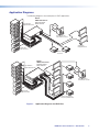
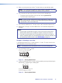
Application Diagrams
The following diagrams show examples of HDXP applications.
Extron
HDXP Plus Series
Multi-Rate Digital
Matrix Switcher
High Definition
Digital Media Servers
TP
UT
S
13
9
ET
5
LAN
RES
1
6
2
ACT LINK
OU
BI-LEVEL
TRI-LEVEL
TCP/IP
15
11
7
3
16
12
8
4
29
25
30
21
S
UT
Remote User and
Administration Control
32
23
28
19
10
24
15
20
11
7
27
18
14
6
2
31
22
13
1
26
17
INP
9
5
16
12
3
8
4
SDI/HD-SDI
Displays/Monitors
Digital Video
Tape Recorders
SDI/HD-SDI
Projectors
Extron
HDXP Plus Series
Multi-Rate Digital
Matrix Switcher
High Definition
Digital Media Servers
TCP/IP
6
O
U
T
P
U
T
S
15
7
RESET
LAN
16
12
8
11
2
29
15
11
7
ACT LINK
3
BI-LEVEL
14
10
6
2
14
10
CK
-LO
GEN
TRI-LEVEL
29
25
21
17
13
9
5
1
16
4
W
VIE
PRE
12
3
8
4
25
30 I
21
26
17
22
13
Remote User and
Administration Control
32
28
19
24
15
20
11
16
7
3
23
14
10
6
2
27
18
9
5
1
N
P
U
31 T
S
12
8
4
Digital Video
Tape Recorders
Plasma/LCD Displays
Projectors (SDI/HD-SDI)
Figure 1.
Application Diagrams for HDXP Plus
HDXP Plus Series Switchers • Introduction
5
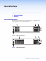
Installation
This section describes the rear panels of the HDXP switchers and provides instructions for
cabling and mounting. Topics include:
•
Rear Panels and Cabling
•
Connections
Rear Panels and Cabling
Most of the HDXP connectors are on the rear panel. Figures 2, 3, and 4 show the rear
panels of the HDXP 1616, 3216, and 3232 switchers.
2
1
9
13
1
5
9
13
2
6
10
14
2
6
10
14
3
7
11
15
3
7
11
15
4
8
12
16
4
8
12
16
5
RESET
LAN
5
Preview
OUTPUTS
1
ACT LINK
INPUTS
3
6
7
8
HDXP 1616 Rear Panel
2
OUTPUTS
1
5
9
13
17
21
25
29
1
5
9
13
2
6
10
14
18
22
26
30
2
6
10
14
3
7
11
15
19
23
27
31
3
7
11
15
4
8
12
16
20
24
28
32
4
8
12
16
Preview
INPUTS
3
5
RESET
ACT LINK
1
LAN
Figure 2.
6
7
8
Figure 3.
HDXP 3216 Rear Panel
HDXP Plus Series Switchers • Installation
6
FIG_HDXP 3232 Rear Panel
2
13
17
21
25
29
10
14
18
22
26
30
3
7
11
15
19
23
27
4
8
12
16
20
24
28
I
N
P
31 U
T
S
32
O
U
T
P
U
T
S
1
5
9
13
17
21
25
29
2
6
10
14
18
22
26
30
3
7
11
15
19
23
27
31
4
8
12
16
20
24
28
32
GEN-LOCK
TRI-LEVEL
9
6
BI-LEVEL
5
2
LAN
1
4
ACT LINK RESET
1
PREVIEW
6
7
3
8
Figure 4.
5
HDXP 3232 Rear Panel
Connections
WARNING: Risk of Electric Shock. Remove power from the system before making
any connections.
ATTENTION: Use Electrostatic discharge precautions (be electrically grounded)
when making connections. Electrostatic discharge (ESD) can damage equipment,
although you may not feel, see, or hear it.
Video Connections
NOTE: The switchers do not alter the video signal in any way. The signal that is output
by the switcher is in the same format as the input signal.
inputs — Connect serial digital input sources to these female BNC
aVideo
connectors.
outputs — Connect serial digital video output devices to these female BNC
bVideo
connectors.
output — Connect a digital display device to this female BNC connector to
cPreview
enable you to preview a selected input when the switcher is in preview mode.
HDXP Plus Series Switchers • Installation
7
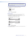
External Sync Connections (HDXP 3232 only)
sync connectors for bi-level and tri-level — Connect an external
dExternal
sync signal to this BNC connector to genlock the video signal in broadcast or other
sync-critical applications.
The HDXP switchers switch between inputs during the vertical interval period,
resulting in glitch-free video switching when the input devices are also using the same
sync timing. The HDXP can use an external signal to synchronize switching during the
vertical interval. Without this external sync locking feature, switching between inputs
could result in a brief rolling (sync loss) or a brief change in the picture size.
Figure 5 shows a basic external sync configuration. The Bi-level or Tri-level sync
connector receives the timing signal. A T connector attached to the cable allows the
signal to be passed on to another video device, if required. Terminate the T connector
if desired.
Extron
BBG 6 A
Black Burst, Color Bars,
and Audio Generator
BBG 6 A
POWER
12V
0.5A MAX
1 KHZ AUDIO
+4dBu
1
R
L
NTSC
BLACK BURST/COLOR BAR
/AUDIO GENERATOR
1
3
5
1 2 3
2
4
6
OUT
ON
-10dBV PAL
BLACKBURST/
COLORBAR
BLACKBURST
25
29
22
26
30
23
27
31
BI-LEVEL
24
28
32
ACT LINK RESET
Connect to
HDXP Plus 3232.
PREVIEW
LAN
TRI-LEVEL
GEN-LOCK
T connector
Terminate cable or
connect to another device.
Extron
HDXP Plus 3232
Matrix Switcher
Figure 5.
Simple HDXP 3232 External Sync Connection Example
HDXP Plus Series Switchers • Installation
8
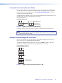
Figure 6 shows a configuration in which the timing source passes through three video
cameras and a video scan converter before connecting to the switcher. This type of
camera can synchronize with the external timing source for video editing applications.
NOTE: I/O grouping is used to set the inputs associated with each reference
input. Input group 1 is associated with the tri-level signal and input group 2 is
associated with the bi-level signal.
Extron
VSC 900D
SDI/HD-SDI
Monitor
VGA Input
Computer-to-Video
Scan Converter
(SDI only)
Extron
HDXP Plus 3232
Extron
BBG 6 A
IN
D1
Matrix Switcher
VID
EO
G
E
N
L
O
C
K
232
RS/422
OUT
DEO
S-VI
V
H/H
B/B
-Y
-Y
G/Y
Blackburst/Color Bars/
Audio Generator
V
H
/HV
2
G
/Y
R
/R-Y
1
0.3A
29
4
DIS
16
7
12
LAN
3
15
10
6
2
29
40V
100-2
I
N
P
U
T
S
RGB
, B-Y,
/R-Y
O
U
T
P
U
T
S
R/R
-Y
V
H
/HV
Y
RGB
Hz
50/60
RESET
15
11
B
/B-Y
B
/B-Y
G-Y
ACT LINK
14
9
5
1
O
U
T
P
U
T
S
ER
IFI
PL
N AM
TIO
IBU
TR
BI-LEVEL
14
10
6
2
TRI-LEVEL
CK
-LO
GEN
25
21
17
13
R
/R-Y
8
11
W
VIE
7
16
PRE
12
3
8
4
25
30 I
21
9
5
6
S
27
18
32
23
28
19
24
15
20
11
2
31 T
22
14
10
1
N
P
U
26
17
13
16
7
12
3
8
4
SDI/HD-SDI
Video Camera
Figure 6.
SDI/HD-SDI
Video Camera
SDI/HD-SDI
Video Camera
Multiple Device Example of an HDXP 3232 External Sync
If no external sync timing source is connected, switching occurs immediately.
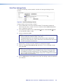
Reset Button
button — This recessed button initiates three levels of reset on the matrix
eReset
switcher. To initiate the different levels of reset, use a pointed object such as a stylus
or a small screwdriver to press and hold the Reset button while the switcher is
running or while you are powering it up (see Resetting on page 37 for details).
•
Events (mode 3) reset — Hold the Reset button until the Reset LED blinks
once (approximately 3 seconds), then release it and press it again momentarily to
toggle events monitoring on and off.
•
IP settings (mode 4) reset — Hold the Reset button until the Reset LED blinks
twice (approximately 6 seconds), then release it and press it again to reset the
switcher IP functions.
NOTE: IP settings reset does not replace any user-installed firmware.
Absolute (mode 5) reset — Hold the Reset button until the Reset LED blinks
three times (approximately 9 seconds), then release it and press it again to restore
the switcher to the default factory settings.
•
Hard reset — Hold the Reset button while powering up the switcher to restore
the switcher to the default factory settings and factory installed firmware version.
NOTE: This type of reset does not clear the current configuration.
HDXP Plus Series Switchers • Installation
9
Ethernet Connection
port — If desired, connect the HDXP switcher to a PC or to an Ethernet LAN
fLAN
via this RJ-45 connector. Use a PC to control the networked switcher with SIS
ACT LINK
Ethernet connection indicators — The Link and Act LEDs indicate the
status of the Ethernet connection. The Link LED indicates that the switcher
is properly connected to an Ethernet LAN. This LED should light steadily.
The Act LED indicates transmission of data packets on the RJ-45 connector.
This LED should flicker as the switcher communicates.
LAN
commands (see the Remote Configuration and Control section, beginning on
page 45), the windows-based control program (see the Matrix Software section,
beginning on page 67), or the HTML pages (see the HTML Configuration and
Control section, beginning on page 96).
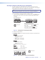
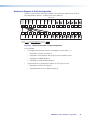
Cabling and RJ-45 connector wiring
It is vital that you use the correct Ethernet cables, and that they be properly
terminated with the correct pinout. Ethernet links use Category (CAT) 5e or CAT 6,
unshielded twisted pair (UTP) or shielded twisted pair (STP) cables, terminated with
RJ-45 connectors. Ethernet cables are limited to a length of 328 feet (100 m).
NOTES:
• Do not use standard telephone cables. Telephone cables do not support
Ethernet or Fast Ethernet.
• Do not stretch or bend cables. Transmission errors can occur.
The Ethernet cable must be properly terminated for your application as either a
crossover or a straight-through cable.
•
Crossover cable — Direct connection between the computer and the
HDXP switcher.
•
Patch (straight) cable — Connection of the HDXP to an Ethernet LAN.
Crossover Cable
Pins:
12345678
Pin
Insert Twisted
Pair Wires
RJ-45
Connector
End 1
Wire Color
Straight-through Cable
End 2
Wire Color
Pin
End 1
Wire Color
End 2
Wire Color
1
White-green
White-orange
1
White-orange
White-orange
2
Green
Orange
2
Orange
Orange
3
White-orange
White-green
3
White-green
White-green
4
Blue
Blue
4
Blue
Blue
5
White-blue
White-blue
5
White-blue
White-blue
6
Orange
Green
6
Green
Green
7
White-brown
White-brown
7
White-brown
White-brown
8
Brown
Brown
8
Brown
Brown
T568A
T568B
T568B
A cable that is wired as T568A at one end
and T568B at the other (Tx and Rx pairs
reversed) is a "crossover" cable.
Figure 7.
T568B
A cable that is wired the same at both ends
is called a "straight-through" cable because
no pin or pair assignments are swapped.
Both ends of the cable can be T568B
(as shown) or T568A (not shown).
RJ-45 Connector and Pinout Tables
HDXP Plus Series Switchers • Installation
10
The cable that you use depends on your network speed. The switcher supports
both 10 Mbps (10Base-T — Ethernet) and 100 Mbps (100Base-T — Fast Ethernet),
half-duplex and full-duplex, Ethernet connections.
•
10Base-T Ethernet requires CAT 3 UTP or STP cable at minimum.
•
100Base-T Fast Ethernet requires CAT 5e UTP or STP cable at minimum.
RS-232 and RS-422 Remote Connections
RS232/RS422 connector — Connect a host device, such as a computer,
gRemote
touch panel control, or RS-232 capable PDA to the switcher via this 9-pin D
1
5
6
9
Figure 8.
RS232 / RS422
REMOTE
connector for serial RS-232 or RS-422 control.
Pin RS-232 Function
RS-422 Function
1
— Not used
—
Not used
2
Tx Transmit data
Tx– Transmit data (–)
3
Rx Receive data
Rx– Receive data (–)
4
— Not used
—
Not used
5
Gnd Signal ground
Gnd Signal ground
6
— Not used
—
Not used
7
— Not used
Rx+ Receive data (+)
8
— Not used
Tx+ Transmit data (+)
9
— Not used
—
Not used
Remote RS232/RS422 Connector
See the Remote Configuration and Control section beginning on page 45 for
definitions of the SIS commands (serial commands to control the switcher via this
connector) and the Matrix Software section beginning on page 67 for details on
how to install and use the control software.
NOTE: The switcher can support either an RS-232 or RS-422 serial
communication protocol, and operate at 9600, 19200, 38400, or 115200 baud
rates (see Selecting the RS-232 or RS-422 Protocol and Baud Rate on
page 36 to configure the RS232/RS422 port from the front panel).
If desired, connect an MKP 2000 or MKP 3000 remote control panel to the switcher
Remote RS232/RS422 connector (see the MKP 2000 Remote Control Panel User’s
Manual and the MKP 3000 User’s Manual for details).
RS-232 Config connector (front panel) — On the HDXP 3232 only, an additional
RS-232 port is located on the front panel. A host device can be connected to this
port for serial RS-232 control only. Protocol for the port is:
•
9600 baud
•
8 data bits
•
1 stop bit
•
No parity
•
No flow control
HDXP Plus Series Switchers • Installation
11
The optional 2.5 mm cable can be used to connect the HDXP to your computer.
Figure 9 shows the pin assignments for this cable.
6 feet
(1.8 m)
1
6
6
5
9
9
Tip
Ring
I
9-pin D
Connection
TRS Plug
Pin 2
Pin 3
Pin 5
Computer Rx line
Computer Tx line
Computer signal ground
Tip
Ring
Sleeve
Figure 9.
Sleeve (Gnd)
2.5 mm Connector Cable for the Configuration Port (HDXP 3232
Only)
See the Remote Configuration and Control section, beginning on page 45, and
the Matrix Software section beginning on page 67 for details about using SIS
commands and the control software to configure the HDXP.
Power
power connector — Plug a standard IEC power cord into this connector to
hAC
connect the switcher to a 100 VAC to 240 VAC, 50 or 60 Hz power source.
HDXP Plus Series Switchers • Installation
12
Operation
This section describes the HDXP front panel controls and the procedures for configuring
and operating the HDXP switchers. Topics include:
•
Front Panel Controls and Indicators
•
Operations
•
Troubleshooting
•
Configuration Worksheets
Front Panel Controls and Indicators
The front panel controls (see figures 10 and 11 on the next page) are grouped into two
sets. The input and output buttons are on the left side of the control panel. The control
buttons and video (I/O) selection buttons are on the right side of the panel.
These illuminated push buttons can be labeled with text and graphics. You can set
the buttons to have amber background illumination all the time, or you can turn off the
background illumination (see Setting the Button Background Illumination on page 35).
The buttons blink or light steadily (depending on the operation) when pressed.
You can re-label the input and output buttons by removing their numbered translucent
covers and inserting new labels behind the covers. An alternative set of labels is provided
and you can also create your own labels using the Extron Button Label Generator software
(also provided). See Creating Button Labels on page 92 for the procedure.
Definitions
The following terms, which apply to Extron matrix switchers, are used in this guide:
•
Tie — An input-to-output connection.
•
Set of ties — An input tied to two or more outputs. (An output can never be tied to
more than one input.)
•
Configuration — One or more ties or one or more sets of ties.
•
Current configuration — The configuration that is currently active in the switcher
(also called configuration 0).
•
Global memory preset — A configuration that has been stored. Up to 32 global
memory presets can be stored in memory. Preset locations are assigned to the input
buttons and (where necessary) output buttons. All models have 32 presets available
from the front panel and under RS-232, RS-422, or Ethernet control.
When a preset is retrieved from memory, it becomes the current configuration.
•
Room — A subset of outputs that are logically related to each other, as determined
by the operator. The switchers support up to 10 rooms, each of which can consist of
from 1 to 16 outputs.
•
Room memory preset — A configuration consisting of outputs in a single room
that has been stored. When a room preset is retrieved from memory, it becomes the
current configuration for the outputs assigned to that room only (none of the other
outputs are affected).
HDXP Plus Series Switchers • Operation
13
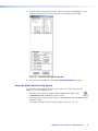
FIG_Front panels
1
INPUTS
1 2 3 4 5 6 7 8 9 10 11 12 13 14 15 16
17 18 19 20 21 22 23 24 25 26 27 28 29 30 31 32
CONTROL
ENTER
PRESET
1 2 3 4 5 6 7 8 9 10 11 12 13 14 15 16
VIEW
<
I/O
ESC
>
OUTPUTS
MATRIX PREVIEW
HDXP PLUS SERIES
SDI AND HD-SDI MATRIX SWITCHER
4
2
5
6
7
8 9
Figure 10. HDXP 1616 and HDXP 3216 Front Panel
NOTE: On the HDXP 1616, which has only 16 input connectors, the input buttons in
the second row (buttons 17 through 32) can be used only for preset selection.
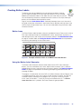
1
1
2 3 4 5
6 7
8 9 10 11 12 13 14 15 16
17 18 19 20 21 22 23 24 25 26 27 28 29 30 31 32
1
2 3 4 5
6 7
8 9 10 11 12 13 14 15 16
17 18 19 20 21 22 23 24 25 26 27 28 29 30 31 32
I
N
P
U
T
S
O
U
T
P
U
T
S
CONTROL
ENTER
PRESET
VIEW
I/O
ESC
VIDEO
AUDIO
CONFIG
HDXP PLUS SERIES
SDI AND HD-SDI MATRIX SWITCHER
2
3
4
5
6
7
8
9
Figure 11. HDXP 3232 Front Panel
Input and Output Buttons
buttons — The input buttons have two primary functions (❏) and three
aInput
secondary functions ( ):
•
❏ Select an input.
❏ Identify the selected input.
•
Input 1 only: With the Output 1 button, place the switcher in I/O grouping mode (see I/O Grouping on page 26).
•
Select a global preset (see Saving and Recalling Presets on page 29).
•
Inputs 1 and 2 only: Activate or deactivate button background illumination (see Setting the Button Background Illumination on page 35).
buttons — The output buttons have two primary functions (❏) and two
bOutput
secondary functions ( ):
•
❏ Select outputs.
❏ Identify the selected outputs.
•
Output 1 only: With the Input 1 button, place the switcher in I/O grouping mode (see I/O Grouping).
•
Mute or unmute an output (see Muting and Unmuting Outputs on page 33).
HDXP Plus Series Switchers • Operation
14
Configuration Port (HDXP 3232 Only)
port (HDXP 3232 only) — This RS-232 port is an alternative to the
cConfig
RS232/RS422 connector on the HDXP rear panel (see Rear Panels and Cabling
on page 6 for a description). This port (RS-232 only) can be used for system
configuration and control via SIS commands or the Windows-based control software.
For information on connecting to this port, see RS-232 and RS-422 Remote
Connections on page 11.
Control Buttons
button — The Enter button has three primary functions (❏) and five
dEnter
secondary ( ) functions:
•
❏ Saves changes that you make on the front panel. To create a simple configuration:
a. Specify a Matrix connection (see I/O Buttons on page 16 [h and i]).
b. Press the desired input button (a).
c. Press the desired output buttons (b).
d. Press the Enter button.
❏ Indicates that a potential tie has been created but not saved.
❏ Indicates that a global preset has been selected to be saved or recalled but that the preset action has not been accomplished.
•
In I/O Grouping mode, selects group 1 (see I/O Grouping on page 26).
•
In I/O grouping mode, indicates that group 1 is selected (see I/O Grouping).
•
Selects the RS-232 or RS-422 protocol and baud rate (see Selecting the
RS-232 or RS-422 Protocol and Baud Rate on page 36).
button — The Preset button has two primary functions (❏) and five
ePreset
secondary ( ) functions:
•
❏ Places the switcher in preset saving mode to save a configuration as a preset, and in preset recalling mode to activate a previously-defined preset.
❏ Blinks when preset saving mode is active, and lights steadily when preset recalling mode is active.
•
In I/O grouping mode, selects group 2 (see I/O Grouping).
•
In I/O grouping mode, indicates that group 2 is selected (see I/O Grouping).
•
Selects the RS-232 or RS-422 protocol and baud rate (see Selecting the
RS-232 or RS-422 Protocol and Baud Rate).
HDXP Plus Series Switchers • Operation
15
< button — The View < button has two primary functions (❏) and eight
fView
secondary ( ) functions:
•
❏ Places the switcher in view-only mode to display the current configuration.
VIEW
<
NOTE: View-only mode also provides a way to mute and unmute outputs
(see Muting and Unmuting Outputs) on page 33).
❏ Indicates that the HDXP is in view-Only mode.
•
In I/O grouping mode, selects group 3 (see I/O Grouping on page 26).
•
In I/O grouping mode, indicates that group 3 is selected (see I/O Grouping).
•
Selects the RS-232 or RS-422 protocol and baud rate (see Selecting the
RS-232 or RS-422 Protocol and Baud Rate on page 36).
> button — The Esc > button has two primary functions (❏) and five
gEsc
secondary ( ) functions:
ESC
>
•
❏ Cancels operations or selections in progress and reset the front panel button indicators.
NOTE: The Esc > button does not reset the current configuration or any
presets.
❏ Flashes once to indicate that the escape function has been activated.
•
In I/O grouping mode, selects group 4 (see I/O Grouping).
•
In I/O grouping mode, indicates that group 4 is selected (see I/O Grouping).
•
Selects the RS-232 or RS-422 protocol and baud rate (see Selecting the
RS-232 or RS-422 Protocol and Baud Rate).
I/O Buttons
You must select the input-output connection mode when you are creating or viewing a
configuration. This is done with the Matrix (h) and Preview (s) buttons.
button — The Matrix button has two primary functions (❏) and four
hMatrix
secondary functions ( ):
•
❏ Places the HDXP in Matrix switching mode, enabling any input to be switched to any output.
❏ Lights green to indicate that the HDXP is in matrix switching mode, and that any input can be selected for switching to any output.
•
With the Preview button, toggles the front panel lock on or off (see Locking the
Front Panel (Executive Mode) on page 35).
•
With the Preview button, initiates the front panel system reset (see Resetting
using front panel buttons on page 38).
•
Selects RS-232 for the rear panel RS232/RS422 port, when the HDXP is in Serial
Port Configuration mode (see Selecting the RS-232 or RS-422 Protocol and
Baud Rate on page 36).
•
Flashes to indicate that the Remote RS232/RS422 port is set to the RS-232
protocol when the switcher is in Serial Port Configuration mode (see Selecting
the RS-232 or RS-422 Protocol and Baud Rate).
HDXP Plus Series Switchers • Operation
16
button — The Preview button has two primary functions (❏) and three
iPreview
secondary functions ( ):
•
❏ Places the HDXP in Preview switching mode, enabling selection of one input to preview.
❏ Lights to indicate that the HDXP is in preview mode, and that only one input can be selected to be viewed.
•
With the Matrix button, toggles the front panel lock on or off (see Locking Out
the Front Panel [Executive mode]).
•
With the Matrix button, initiates the front panel system reset (see Resetting
using front panel buttons).
•
Selects RS-422 for the rear panel RS232/RS422 port when the switcher is in
Serial Port Configuration mode (see Selecting the RS-232 or RS-422 Protocol
and Baud Rate).
•
Flashes to indicate that the RS232/RS422 port is set to the RS-422 protocol
when the HDXP is in Serial Port Configuration mode (see Selecting the RS-232
or RS-422 Protocol and Baud Rate).
Operations
The following sections detail the powering up process and provide procedures for
operations that can be performed from the front or rear panel.
Powering On
Apply power by connecting the power cord to an AC source. The switcher performs a
self-test that flashes the front panel button indicators red, green, and amber and then
turns them off (the order of button LED colors may vary by model). An error-free powerup self-test sequence leaves all input, output, and control buttons either unlit or showing
background illumination. The lit or unlit status of the Matrix and Preview buttons is the
same as it was when the switcher was powered off.
The current configuration and all presets are saved in memory. When power is applied,
the most recent configuration is retrieved. The previous presets remain intact. If an error
occurs during the self-test, the HDXP locks up and does not operate. If your switcher
locks up on power-up, call the Extron S3 Support Hotline.
Creating a Configuration
A configuration consists of one or more inputs, each tied to a set of outputs. To set up a
configuration, you must place the HDXP in matrix switching mode, which enables you to
switch any input to any output.
NOTE: While an input can be tied to multiple outputs, an output can be tied to only
one input.
This section contains the steps to follow to create or change a configuration. The
following subsections contain some examples of configurations that can be created on
the HDXP, and instructions on setting them up. The illustrations show the HDXP 3216;
however, the procedures apply to all HDXP models.
1. Press the Esc > button to clear any pending changes or input, output, or control
button indicators that may be lit.
2. Press the Matrix button in the I/O section. The Matrix button lights green (the Preview
button remains unlit).
HDXP Plus Series Switchers • Operation
17
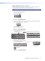
3. Select an input by pressing its button. The input button you pressed lights green.
NOTE: If your selected input already has outputs tied to it, the buttons of the tied
outputs also light green (steadily) when you press the input button.
4. Press the button for each output that you want to tie to the selected input.
•
The output buttons blink green when pressed, indicating potential ties.
•
The Enter button also blinks green.
NOTE: Outputs that are already tied can remain tied (buttons lit), along with your
new blinking selections; or you can untie them by pressing their associated
output buttons, which start to blink also.
5. Press Enter to establish the tie. The input, output, and Enter buttons become unlit.
6. Repeat steps 3 through 5 to create additional ties until the desired configuration is
complete.
NOTES:
• Only one input can be tied to an output. If you tie an input to an output that is
already tied to another input, the older tie is broken in favor of the newer tie.
• If you press the input button for an I/O grouped input and then try to select an
output in a different group, the associated output button cannot be selected, and
the selected input button remains lit (see I/O Grouping on page 26).
Example 1: Creating a set of ties
In the following example, input 5 is tied to outputs 3, 4, and 8. The steps show the front
panel indications that result from your action.
NOTE: This example assumes that there are no ties in the current configuration.
1. Press and release the Esc > button.
Press the Esc > to clear all selections.
CONTROL
ENTER PRESET
VIEW
ESC
The button blinks once.
Figure 12. Clearing All Selections
2. If necessary, place the HDXP in matrix switching mode by pressing and releasing the
Matrix button. The button lights steadily green.
I/O
MATRIX
PREVIEW
Press the Matrix button to enter matrix mode.
The button lights green when selected.
Figure 13. Selecting Matrix Mode
HDXP Plus Series Switchers • Operation
18
3. Press and release the Input 5 button.
Press and release the Input 5 button.
The button lights green.
INPUTS
1
2
3
4
5
6
7
8
17 18 19 20 21 22 23 24
Figure 14. Selecting Input 5
4. Press and release the Output 3, Output 4, and Output 8 buttons.
Press and release the Output 3, Output 4, and Output 8 buttons.
The buttons blink green to indicate that the selected input will be
tied to these outputs.
1
2
3
4
5
6
7
8
CONTROL
OUTPUT
ENTER PRESET
VIEW
ESC
The Enter button blinks
green to indicate the need to
confirm the change.
= Blinking Button
Figure 15. Selecting the Outputs
NOTE: The entire set of ties can be canceled at this point by pressing and
releasing the Esc > button. The Esc > button flashes red once.
5. Press and release the Enter button.
Press the Enter button to
confirm the configuration
change.
All input and output buttons
become unlit or return to
background illumination.
ENTER
The Enter button
becomes unlit or returns to
background illumination.
Figure 16. Confirming the Tie
The configuration now is:
Input 5 tied to output 3, output 4, and output 8
Input 5 Tied to
Outputs 3, 4, and 8
Input
5
3
4
Output
8
Figure 17. Example 1, Final Configuration
HDXP Plus Series Switchers • Operation
19
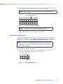
Example 2: Adding a tie to a set of ties
In the following example, a new tie is added to the current configuration. The illustrations
show the front panel indications that result from your actions.
NOTE: This example assumes that you have performed example 1.
1. Press and release the Esc > button.
Press the Esc > to clear all selections.
CONTROL
ENTER PRESET
VIEW
ESC
The button blinks once.
Figure 18. Clearing All Selections
2. If necessary, place the HDXP in matrix switching mode by pressing and releasing the
Matrix button. The button lights steadily green.
I/O
MATRIX
PREVIEW
Press the Matrix button to enter matrix mode.
The button lights green when selected.
Figure 19. Selecting Matrix Mode
3. Press and release the Input 5 button.
Press and release the Input 5 button.
The button lights green.
The Output 3, Output 4, and Output 8 buttons
light green to indicate the ties created in example 1.
INPUTS
1
2
3
4
5
6
7
1
8
2
3
4
5
6
7
8
OUTPUT
17 18 19 20 21 22 23 24
Figure 20. Selecting an Input with Ties
4. Press and release the output 1 button.
Press and release the Output 1 button.
The button blinks green to indicate that the
selected input will be tied to this output.
1
2
3
4
5
6
7
CONTROL
8
ENTER PRESET
VIEW
ESC
OUTPUT
The Enter button blinks
green to indicate the need to
confirm the change.
= Blinking button
Figure 21. Selecting an Additional Output
HDXP Plus Series Switchers • Operation
20
5. Press and release the Enter button.
Press the Enter button to
confirm the configuration
change.
ENTER
All input and output buttons
become unlit or return to
background illumination.
The Enter button
becomes unlit or returns to
background illumination.
Figure 22. Confirming the Tie
The configuration now is:
Input 5 tied to output 1, output 3, output 4, and output 8
Input 5 tied
to outputs 1, 3, 4, and 8.
Input
5
1
3
4
Output
8
Figure 23. Example 2, Final Configuration
Breaking ties
To undo an existing I/O tie:
1. Press the Matrix button. The button lights green.
2. Press the input button whose tie you want to dissolve. The input button and its tied
output buttonslight green.
3. Press one of the lit output buttons. The button you pressed, and the Enter button,
start to blink.
4. Press the Enter button. The input, output, and Enter buttons become unlit, and the tie
is broken.
HDXP Plus Series Switchers • Operation
21
Example 3: Removing a tie from a set of ties
In the following example, an existing tie is removed from the current configuration. The
steps show the front panel indications that result from your action.
NOTE: This example assumes that you have performed examples 1 and 2.
1. Press and release the Esc > button.
Press the Esc > to clear all selections.
CONTROL
ENTER PRESET
VIEW
ESC
The button blinks once.
Figure 24. Clearing All Selections
2. If necessary, place the HDXP in matrix switching mode by pressing and releasing the
Matrix button. The button lights steadily green.
I/O
MATRIX
PREVIEW
Press the Matrix button to enter matrix mode.
The button lights green when selected.
Figure 25. Selecting Matrix Mode
3. Press and release the input 5 button.
Press and release the Input 5 button.
The button lights green.
The Output 1, Output 3, Output 4, and Output 8 buttons
light green to indicate the ties created in examples 1 and 2.
INPUT
1
2
3
4
5
6
7
1
8
2
3
4
5
6
7
8
17 18 19 20 21 22 23 24
17 18 19 20 21 22 23 24
OUTPUT
Figure 26. Selecting an Input
4. Press and release the Output 4 button.
Press and release the Output 4 button.
The button blinks green to indicate the pending change: output 4 will be untied.
C O NT R O L
ENTER PRESET
1
2
3
4
5
6
7
8
OUTPUT
VIEW
ESC
The Enter button blinks
green to indicate the need to
confirm the change.
= Blinking button
Figure 27. Deselecting the Output
HDXP Plus Series Switchers • Operation
22
5. Press and release the Enter button.
Press the Enter button to
confirm the configuration
change.
ENTER
All input and output buttons
become unlit or return to
background illumination.
The Enter button
becomes unlit or returns to
background illumination.
Figure 28. Confirming the Tie Removal
The configuration now is:
Input 5 tied to output 1, output 3, and output 8 (see figure 29).
Input 5 tied to
outputs 1, 3, 4, and 8.
Input
5
1
3
Output
8
Figure 29. Example 3, Final Configuration
Previewing an Input
You can preview any input by switching it to the preview output when the HDXP is in
preview mode. To preview an input:
1. Press the Esc > button to clear any input, output, or control button indicators that
may be lit.
2. Press the Preview button in the I/O section. The Preview button lights red (the Matrix
button is unlit).
I/O
MATRIX PREVIEW
Press the Preview button to enter preview mode.
The button lights red when selected.
Figure 30. Selecting Preview Mode
NOTE: If an input has already been selected in preview mode, its button also
lights red when you press Preview.
HDXP Plus Series Switchers • Operation
23
3. Press the button for the input that you want to preview. The input button lights red
when pressed, and the selected input is tied to the Preview output.
NOTE: Preview selection mode times out and returns to matrix mode after
30 seconds of non-use.
Press and release the desired input
button. The button lights red.
INPUTS
1
2
3
4
5
6
7
8
17 18 19 20 21 22 23 24
Figure 31. Selecting an Input to Preview
NOTE: Only one input at a time can be previewed. If another input
button was lit when you pressed Preview, it becomes unlit.
4. Repeat steps 2 and 3 if you want to preview another input.
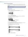
Viewing the Configuration
The current configuration can be viewed using the front panel buttons. The view-only
mode prevents inadvertent changes to the current configuration. View-only mode also
provides a way to mute outputs (see Muting and Unmuting Outputs on page 33).
NOTE: You cannot view configurations while the HDXP is in preview mode.
When you place it in view-only mode, the HDXP also switches to Matrix
mode. If you want to return the HDXP to preview mode, you must press
the Preview button again.
View the current configuration as follows:
1. Press the Esc > button to clear any input button indications, output button
indications, or control button indications that may be on.
Press the Esc > to clear all selections.
CONTROL
ENTER PRESET
VIEW
ESC
The button blinks once.
Figure 32. Clearing All Selections
HDXP Plus Series Switchers • Operation
24
2. Press and release the View < button.
Press the View button
to enter view-only mode.
CONTROL
ENTER PRESET
VIEW
ESC
The button lights red.
Figure 33. Entering View-only Mode
•
The View < button lights red.
•
The Matrix button lights green.
•
All of the buttons for outputs that are not tied light green.
3. Select the input or output whose ties you wish to view by pressing its input or output
button.
Press and release the desired input button.
The button lights green.
1
2
3
4
5
6
7
The buttons for outputs that are tied to the selected input light green.
8
1
2
3
4
5
6
7
8
OUTPUT
17 18 19 20 21 22 23 24
The buttons for outputs that are not tied to the selected input are unlit.
Figure 34. Selecting an Input to View in View-only Mode
•
When you press the button for an input or an output that has ties, the buttons for
all the inputs and outputs tied to it light green.
•
When an output button for which there are no ties is pressed, the buttons also
light for all other outputs without ties.
NOTE: You can also view a set of ties by selecting a tied output. To demonstrate
this, note the number of a lit output button, and then press and release the
output button for an untied (unlit) output. Observe that all of the untied outputs
light. Then press the output button that you noted previously and observe that
the selected output button, the tied input button, and the output buttons light for
all of the outputs that are tied to the input.
4. To exit view-only mode, press View < again; or wait for the View < button to turn off
(approximately 30 seconds).
Press the View button
to exit view-only mode.
VIEW
All input and output buttons
become unlit or return to
background illumination.
The View button becomes
unlit or returns to
background illumination.
Figure 35. Exiting View-only Mode
HDXP Plus Series Switchers • Operation
25
I/O Grouping
I/O grouping is a matrix switcher feature that allows you to subdivide the front panel
control of the matrix into four smaller functional sub-switchers and limit tie creation from
the front panel only. Inputs and outputs can be assigned to one of four groups or not
assigned to any group.
Inputs and outputs that are assigned to a group can be tied only to other outputs and
inputs within the same group when you are creating ties on the front panel. For example,
you cannot tie an input that is assigned to group 1 to an output that is assigned to
group 2. Ungrouped inputs and outputs can be switched to outputs and inputs in any
group. Ties between groups (for example, an input in group 1 tied to an output in group 2)
can be created via SIS commands, the Matrix Switcher Control Program, or Ethernet
control.
You can set up the I/O groups by the following methods:
•
Front panel buttons and menus (see Creating I/O groups on page 27)
•
SIS commands via RS-232, RS-422, or Ethernet control (see the Remote
Configuration and Control section beginning on page 45)
•
The Matrix Switcher Control Program via Telnet/RS-232/RS-422 or IP control (see the
Matrix Software section beginning on page 67)
HDXP 3232 only: Outputs assigned to I/O group 1 reference the bi-level genlock sync
signal for vertical interval switching; outputs assigned to I/O group 2 reference the tri-level
genlock sync signal.
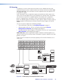
Figure 36 gives an example of input-output grouping of SDI and HD-SDI devices on an
HDXP 3232.
1
2 3 4 5
6 7
8 9 10 11 12 13 14 15 16
I
N
P
U
T
S
17 18 19 20 21 22 23 24 25 26 27 28 29 30 31 32
1
2 3 4 5
6 7
O
U
T
P
U
T
S
8 9 10 11 12 13 14 15 16
17 18 19 20 21 22 23 24 25 26 27 28 29 30 31 32
Group 1
Group 2
Group 3
Editing Station
SDI/HD-SDI #1
SDI/HD-SDI
Monitor
3 input, 4 output
SDI/HD-SDI matrix
Input
24 25 26
SDI/HD-SDI
Monitor
5
6 Output
7
8
Group 3
Editing Station
SDI/HD-SDI #3
SDI/HD-SDI
Monitor
DVS 304 IP
SDI/HD-SDI
Camera #1
4 input, 2 output
SDI/HD-SDI matrix
Input
17 18 19 20
3 input, 2 output
SDI/HD-SDI matrix
SDI/HD-SDI
Monitor
SDI/HD-SDI VTR
(MPEG-2/JPEG 2000) #1
1
2 Output
SDI/HD-SDI
Camera #4
DIGITAL VIDEO SCALER
ADJUST
1
2
3
4
MENU
NEXT
IR
DVS 304 (SDI only)
Input
21 22 23
3
Output
4
Group 1
Group 2
SDI/HD-SDI
Monitor
SDI/HD-SDI VTR
(MPEG-2/JPEG 2000) #3
SDI/HD-SDI
Monitor
Figure 36. I/O Grouping of Incompatible Video Formats
HDXP Plus Series Switchers • Operation
26
Suggested applications for the I/O grouping feature include:
•
Segregating specific video formats to prevent an input in one video format from
being inadvertently applied to an output device that supports another video format
(see figure 37).
•
Segregating input and output devices that are in separate rooms.
•
Isolating video from being displayed on specific output devices for operational security
reasons.
NOTES:
• Presets can be created under RS-232, RS-422, or Ethernet control to tie inputs
and outputs across group boundaries. These presets are selectable from the
front panel.
• An input or output can be assigned to only one group. If you assign an input
or output to a group, and that input or output is already assigned to a different
group, the older grouping is replaced by the new grouping.
• For I/O groups to have any function, at least two groups must be created.
Creating I/O groups
Follow these steps to create I/O groups using the front panel:
NOTE: The illustrations in this section show the HDXP 3216. However, the procedure
applies to all three HDXP models.
1. Press the Esc > button to clear any input buttons, output buttons, or control buttons
that may be lit. The Esc > button blinks once, then turns off.
Press the Esc > to clear all selections.
CONTROL
ENTER PRESET
VIEW
ESC
The button blinks once.
Figure 37. Clearing All Selections
2. To enter I/O grouping mode, press and hold the Input 1 and Output 1 buttons
simultaneously, until the buttons for all the ungrouped inputs and outputs light green
(approximately 3 seconds). If no groups have been formed, all the input and output
buttons light.
Inputs
1
Press and hold the
Input 1 button and
the Output 1 button.
2
Release the Input 1 button
and the Output 1 button.
17 18
3 Seconds
1
2
Ungrouped input and
output buttons light.
1
1
Outputs
Figure 38. Selecting I/O Group Mode
HDXP Plus Series Switchers • Operation
27
3. Press and release one of the Control buttons to select a group number:
•
Press the Enter button to select group 1.
•
Press the Preset button to select group 2.
•
Press the View < button to select group 3.
•
Press the Esc > button to select group 4.
In the figure 39 example, group 1 is being selected.
Press the Enter button to select group 1.
The button lights amber to indicate the selection.
CONTROL
ENTER PRESET
Group#
1
2
VIEW
ESC
3
4
Figure 39. Selecting an I/O Group Number
4. Select the desired inputs and outputs to assign to the group by pressing their input
and output buttons. In the example below, inputs and outputs 1 through 4 are being
selected.
Press and release Input buttons 1 through 4. The selected buttons light.
INPUTS
1
2
3
4
5
6
7
8
17 18 19 20 21 22 23 24
Press and release Output buttons 1 through 4. The selected buttons light.
1
2
3
4
5
6
7
8
OUTPUT
Figure 40. Assigning Inputs and Outputs to a Group
5. In order for an input group to be functional, you must create more than one group.
Repeat steps 3 and 4 to create a second input group.
6. If you want to create more I/O groups, repeat steps 3 and 4 again.
7. When finished grouping, press and release the Matrix and Preview buttons to exit the
I/O grouping mode.
I/O
MATRIX
PREVIEW
Press the Matrix and Preview button
simultaneously to exit I/O grouping mode.
Figure 41. Exiting I/O Grouping Mode
Alternatively, you can allow the mode to time out by waiting approximately 30
seconds.
HDXP Plus Series Switchers • Operation
28
Viewing I/O groups
To see the groupings that have been created:
1. Press and hold the Input 1 and Output 1 buttons until all ungrouped buttons light
green (approximately 3 seconds).
2. Press the Control button for the group number you want to view (Enter = group 1,
Preset = group 2, View < = group 3, and Esc > = group 4). The buttons for all inputs
and outputs in that group light green.
3. To view another group, repeat step 2.
4. When finished viewing groups, wait 30 seconds for grouping mode to time out, or
press the Matrix and Preview buttons simultaneously.
Saving and Recalling Presets
The current configuration (configuration 0) can be saved as a preset in any one of 32
preset memory addresses. Preset locations are assigned to the input buttons and (where
necessary) output buttons. Up to 32 presets can be selected from the front panel to be
either saved or recalled. When a preset is recalled from memory via the front panel, it
becomes the current configuration.
NOTES:
• Presets cannot be viewed from the front panel unless recalled as the current
configuration. Presets that are not the current configuration can be viewed using
the Matrix Switcher Control Program (see the Matrix Software section beginning
on page 67 for more details).
The current configuration and all other presets are stored in non-volatile memory.
When power is removed and restored, the current configuration remains active
and all presets are retained.
• When a preset is recalled, it replaces the current configuration, which is lost
unless it is also stored as a preset. The recalled preset overwrites all of the
current configuration ties in favor of its own ties.
• Figure 42 shows the presets associated with the input and output buttons on
each HDXP model. (On the HDXP 1616, which has only 16 input connectors,
input buttons 17 through 32 are used for presets, but not for input selection.)
HDXP 3232
Preset Preset Preset Preset Preset Preset Preset Preset Preset Preset Preset Preset Preset Preset Preset Preset
1
2
3
4
5
6
7
8
9
10
11
12
13
14
15
16
1
2
3
4
5
6
7
8
9 10 11 12 13 14 15 16
17 18 19 20 21 22 23 24 25 26 27 28 29 30 31 32
I
N
P
U
T
S
Preset Preset Preset Preset Preset Preset Preset Preset Preset Preset Preset Preset Preset Preset Preset Preset
17
18
19
20
21
22
23
24
25
26
27
28
29
30
31
32
HDXP 3216 and HDXP 1616
Preset Preset Preset Preset Preset Preset Preset Preset Preset Preset Preset Preset Preset Preset Preset Preset
1
2
3
4
5
6
7
8
9
10
11
12
13
14
15
16
INPUTS
1
2
3
4
5
6
7
8
9 10 11 12 13 14 15 16
17 18 19 20 21 22 23 24 25 26 27 28 29 30 31 32
Preset Preset Preset Preset Preset Preset Preset Preset Preset Preset Preset Preset Preset Preset Preset Preset
17
18
19
20
21
22
23
24
25
26
27
28
29
30
31
32
Figure 42. Preset Locations on the HDXP 3232, 3216, and 1616
HDXP Plus Series Switchers • Operation
29
Saving a preset
Follow these steps to save the current configuration (set of ties) as a preset. The steps
show the front panel indications that result from your action.
NOTE: The illustrations for this procedure show the HDXP 3216. However, the
information applies to all HDXP models.
1. Press and release the Esc > button.
Press the Esc > to clear all selections.
CONTROL
ENTER PRESET
VIEW
ESC
The button blinks once.
Figure 43. Clearing All Selections
2. Press and hold the Preset button for approximately 2 seconds, until it blinks.
PRESET
2 seconds
Red
(Preset Assigned)
PRESET
1
Press and hold the Preset button until it blinks.
All input buttons with assigned presets light red.
If you then save the configuration to a lit preset number,
the configuration data at that preset location will be overwritten.
2
Inputs
17 18
Unlit
(No Preset Assigned)
= Blinking button
Figure 44. Entering Save Preset Mode
In this illustration, preset 2 has already been assigned; therefore, the Input 2 button
lights red when preset mode is entered.
3. Press and release the input or output button for the desired preset number.
Press and release an input button.
The button blinks red to indicate that this
preset number is selected but not saved.
C O NT R O L
ENTER PRESET
VIEW
ESC
INPUTS
1
2
3
4
5
6
7
The Enter button blinks to
indicate the need to save the
preset.
8
17 18 19 20 21 22 23 24
The Preset button continues to
blink.
= Blinking button
Figure 45. Selecting the Preset Number
HDXP Plus Series Switchers • Operation
30
4. Press and release the Enter button. The current configuration is now stored in the
selected memory location.
Press the Enter button to
save the preset.
C O NT R O L
ENTER PRESET
VIEW
ESC
All input buttons become unlit or
return to background illumination.
The Enter and Preset buttons
become unlit or return to
background illumination.
Figure 46. Press the Enter Button
Recalling a preset
Follow these steps to recall a preset (set of ties) to be the current configuration. The steps
below show the front panel indications that result from your action.
NOTE: The illustrations for this procedure show the HDXP 3216. However, the
information applies to all HDXP models.
1. Press and release the Esc > button.
Press the Esc > to clear all selections.
CONTROL
ENTER PRESET
VIEW
ESC
The button blinks once.
Figure 47. Clear All Selections
2. Press and release the Preset button.
Red
(Preset Assigned)
PRESET
Press and release the Preset button.
The Preset button lights.
All input buttons with
assigned presets light red.
1
2
Inputs
17 18
Unlit
(No Preset Assigned)
Figure 48. Entering Recall Preset Mode
In the example in figure 48, the Input 2 button lights red, because a preset has been
assigned to it. Input button 17 does not light, because no preset has been assigned
to it.
HDXP Plus Series Switchers • Operation
31
3. Press and release the input or output button for the desired preset. In figure 49,
preset 1 (Input button 1) is selected.
Press and release the Input 1 button.
The button blinks red to indicate that this
preset number is selected but not recalled.
C O NT R O L
ENTER PRESET
VIEW
ESC
INPUTS
1 2 3 4 5 6 7 8 9
17 18 19 20 21 22 23 24 2
The Enter button blinks
to indicate the need to
recall the preset.
= Blinking Button
Figure 49. Select the Preset
4. Press and release the Enter button (see figure 50). The configuration stored in
selected memory location is now the current configuration and can be viewed in
view-only mode (see Viewing the Configuration on page 24).
Press the Enter button to
recall the preset.
C O NT R O L
ENTER PRESET
VIEW
The Enter and Preset
buttons become unlit or
return to background
illumination.
ESC
All input buttons become unlit or
return to background illumination.
1
2
Inputs
17 18
Figure 50. Pressing Enter to Recall the Preset
5. Press and release the View < button to return the HDXP to normal switcher
operation.
HDXP Plus Series Switchers • Operation
32
Muting and Unmuting Outputs
You can mute and unmute the outputs on the HDXP using the front panel. (You can also
mute and unmute them via SIS commands, the Windows-based control software, and the
web pages.)
NOTE: Mutings are saved to memory. When power is removed and restored, the
mute settings are retained.
Muting an output
Follow these steps to mute an output:
1. Press the Esc > button to clear any input button indications, output button
indications, or control button indications that may be on.
Press the Esc > to clear all selections.
CONTROL
ENTER PRESET
VIEW
ESC
The button blinks once.
Figure 51. Clearing All Selections
2. Press and release the View < button to enter view-only mode. The View < button
lights red, and all untied output buttons light green.
Press the View < button to
enter view-only mode.
C O NT R O L
ENTER PRESET
VIEW
ESC
The View button lights red.
All output buttons that have
not been tied light green.
Figure 52. Entering View-only Mode
3. Press and hold the button for the desired output until the output button starts to blink
(approximately 2 seconds). This indicates that the output is muted.
4. Repeat step 3 for each output that you want to mute.
In the following illustration, outputs 3 and 4 are muted.
Mute outputs one at a time.
3
2 seconds
Press and hold the Output 3 button.
4
3
The button blinks green to indicate
that the outputs are muted.
2 seconds
Press and hold the Output 4 button.
4
The button blinks green to indicate
that the outputs are muted.
= Blinking button
Figure 53. Muting the Outputs
HDXP Plus Series Switchers • Operation
33
NOTE: The front panel times out after 30 seconds, and the View < and the
blinking output buttons become unlit or return to background lighting. If you
want to mute another output after a timeout, you must press the View < button
again (repeat steps 2 and 3).
5. When finished muting, press and release the View < button to exit view-only mode, or
wait for the front panel to time out (approximately 30 seconds).
Press the View button
to exit view-only mode.
VIEW
All input and output buttons
become unlit or return to
background illumination.
The View button becomes
unlit or returns to
background illumination.
Figure 54. Exiting View-only Mode
Unmuting an output
1. Press and release the View < button to enter view-only mode. The View < button
lights red, and the buttons for any muted inputs begin blinking green.
2. One at a time, press and hold the button for each output that you want to unmute
until the button lights steadily (approximately 2 seconds).
In the following illustration, outputs 3 and 4 are unmuted.
Unmute outputs one at a time.
3
2 seconds
3
Press and hold the Output 3 button.
The button lights green to indicate
that the outputs are not muted.
4
2 seconds
4
Press and hold the Output 4 button.
The button lights green to indicate
that the outputs are not muted.
= Blinking button
Figure 55. Unmuting the Outputs
3. Press the View < button to exit view-only mode, or wait for the front panel to time out
after approximately 30 seconds.
HDXP Plus Series Switchers • Operation
34
Locking the Front Panel (Executive Mode)
The front panel security lockout (executive mode) limits the operation of the HDXP from
the front panel. When the switcher is locked, all of the front panel functions are disabled
except for the view-only mode functions (see Viewing the Configuration on page 24)
and front panel lock mode selection.
To toggle executive mode on and off, press and hold the Matrix and Preview buttons until
the two buttons blink twice (approximately 3 seconds).
Press and hold the Matrix and
Preview buttons simultaneously to
toggle executive mode on or off.
I/O
MATRIX
I/O
PREVIEW
2 seconds
MATRIX
PREVIEW
The Matrix and
Preview buttons blink
twice to indicate the
mode change.
Release the buttons.
Figure 56. Toggling Front Panel Lock On and Off
If you press a front panel button when the switcher is locked, the Matrix and Preview
buttons flash twice, then return to their previous state.
NOTE: This does not occur in view-only mode or when you press the two I/O buttons
to enter or exit executive mode.
Setting the Button Background Illumination
You can set the buttons on the front panel to have amber background illumination at all
times, or you can turn the background illumination off.
To toggle the background illumination on or off, press and hold the Input 1 and Input 2
buttons until the button background changes (approximately 2 seconds).
Press and hold the Input 1 and Input 2
buttons simultaneously to toggle
background illumination mode on or off.
1
2
17 18
2 seconds
1
2
17 18
Release the Input 1
and Input 2 buttons.
Figure 57. Toggling Background Illumination On or Off
HDXP Plus Series Switchers • Operation
35
Selecting the RS-232 or RS-422 Protocol and Baud Rate
The HDXP switchers can support either RS-232 or RS-422 serial communication
protocol, and operate at 9600, 19200, 38400, and 115200 baud rates. The settings of
these variables can be viewed and changed from the front panel.
NOTE: This information applies to only the rear panel Remote RS232/RS422 port.
The front panel Config port is RS-232 only; RS-422 cannot be selected for it.
View and configure the serial communications settings as follows:
1. To enter serial port configuration mode, simultaneously press and hold all Control
buttons (Enter, Preset, View <, and Esc >) until all buttons light (approximately
2 seconds).
Press and hold the Enter, Preset,
View <, and Esc > buttons.
ENTER PRESET
VIEW
I/O
C O NT R O L
C O NT R O L
ESC
2 seconds
ENTER PRESET
VIEW
ESC
MATRIX
PREVIEW
All Control buttons light with one flashing.
Both I/O buttons light with one flashing.
The flashing Control button indicates the baud rate as follows:
Enter — 9600
Preset — 19200
Esc > — 115200
View < — 38400
= Blinking button
The flashing I/O button indicates the protocol as follows:
Matrix — RS-232 Preview — RS-422/RS-485
In this example, the port is set to RS-232 at 9600 baud.
Figure 58. Enabling Serial Port Configuration Mode
2. Release the Control buttons.
3. To change a value, press and release the button that relates to the desired value.
Baud rate:
•
Enter selects 9600 baud.
•
Preset selects 19200.
•
View < selects 38400 baud.
•
Esc > selects 115200 baud.
Protocol:
•
Matrix selects RS-232
•
Preview selects RS-422.
Press and release the button(s) to configure the port as
follows:
Baud rate:
Enter — 9600
Preset — 19200
Esc > — 115200
View < — 38400
Serial protocol:
Matrix — RS-232
Preview — RS-422/RS-485
The selected buttons blink and the others remain lit.
In this example, the port is set to RS-422 at 38400 baud.
= Blinking button
I/O
C O NT R O L
ENTER PRESET
VIEW
ESC
MATRIX PREVIEW
Figure 59. Selecting RS-232 or RS-422 and the Baud Rate
HDXP Plus Series Switchers • Operation
36
4. Press and release an input or output button to exit the serial port configuration mode.
All Control and I/O buttons become unlit
or return to background illumination.
Press and release an
input or output button.
I/O
C O NT R O L
5
ENTER PRESET
VIEW
ESC
MATRIX
PREVIEW
Figure 60. Exiting Serial Port Configuration Mode
Resetting
There are several methods by which you can reset the HDXP, and some of these methods
allow for four levels of resetting. The following reset methods are available on the HDXP:
•
Front panel buttons
•
Rear panel reset button
•
SIS commands
•
Windows-based control software
The front panel and rear panel reset methods are discussed in this section. For information
about resetting via SIS commands, see the Remote Configuration and Control section
beginning on page 45. For information about using the Windows-based software to reset,
see the Matrix Software section beginning on page 67.
Resetting using front panel buttons
The front panel (system) reset is identical to the E ZXXX } SIS command, which returns
the HDXP to its factory-set defaults (see the Remote Configuration and Control
section). A system reset clears all ties, presets, and output muting, and resets all I/O
grouping.
To reset the switcher to the factory default settings, press and hold the Matrix and
Preview buttons while you apply AC power to the switcher.
NOTE: System reset does not reset the Internet protocol (IP) settings or replace
user-installed firmware.
Press and hold the Matrix and Preview buttons
while you apply power to the switcher.
I/O
MATRIX
PREVIEW
Power
The I/O buttons blink red, green, amber, then off.
Continue to hold the Matrix and Preview buttons until all input and
output buttons become unlit and the Matrix button lights green.
Release the Matrix and Preview buttons.
Figure 61. Resetting the System from the Front Panel
HDXP Plus Series Switchers • Operation
37
Resetting using the rear panel Reset button
The rear panel has a Reset button that initiates four levels of matrix switcher resets. This
button is recessed; it can be accessed with a pointed stylus, ballpoint pen, or an Extron
Tweeker (a small screwdriver provided with the unit). While the switcher is running or while
you are applying power to it, press and hold in the button for the number of seconds
required for the desired reset level.
The table below provides a summary of the rear panel reset modes.
Reset Modes Summary
Mode
Activation
Result
Purpose
1
Hold in the Reset button while applying Restores the factory-installed firmware. It
power to the switcher.
does not clear the current configuration.
3
Hold in the Reset button until
the Reset LED blinks once (after
approximately 3 seconds); then within
1 second press Reset momentarily
(for less than 1 second).
Turns events (such as on and off. During Mode 3 is useful
resetting, the Reset LED blinks two times for troubleshooting.
if events are starting or three times if
events are stopping.
4
Hold in the Reset button until the
Reset LED blinks twice (once after
approximately 3 seconds and again
after 6 seconds); then within 1 second
press Reset momentarily (for less than
1 second).
• Enables ARP capability.
• Sets the IP address, subnet address,
and gateway address to the factory
defaults.
• Sets port mapping to the factory
default.
• Turns DHCP off.
• Turn events off.
Mode 1 can be
used to remove a
version of firmware
if incompatibility
issues arise.
Mode 4 enables
you to set
IP address
information using
ARP and the MAC
address.
It does not replace
any user-installed
firmware.
The Reset LED blinks four times in quick
succession during the reset.
5
Hold in the Reset button until the
Reset LED blinks three times (once
after approximately 3 seconds, again
after 6 seconds, and then again after
9 seconds); then within 1 second
press Reset momentarily (for less than
1 second).
Performs a complete reset to factory
defaults (with the exception of the
firmware), which includes:
• Everything mode 4 does
• Reset of almost all real time
adjustments:
Mode 5 is useful
if you want to
start over with
configuration and
uploading and also
to replace events.
• Clears all ties, presets, audio or
RS-232 mutes, and I/O grouping.
• Resets all IP options.
• Removes or clears all switcher
files.
The reset LED blinks four times in quick
succession during the reset.
NOTE: Mode 5 reset clears most adjustments. To save these settings, use the Matrix Switchers
Control Program and select Save MATRIX settings as... from the File menu before you
perform this reset (see the Matrix Switcher Control Program help file for more information).
HDXP Plus Series Switchers • Operation
38
Soft system resets
The HDXPs have three soft resets available that restore various tiers of switcher settings
to their default settings.
•
Events (mode 3) reset — This function toggles the monitoring of events on or off (if
events monitoring was on, this function turns it off; if monitoring was on, the HDXP
turns it off).
•
IP settings (mode 4) reset — The IP settings reset performs the following functions:
•
Enables Arp program capability.
•
Resets the IP address to the factory default (192.168.254.254).
•
Resets the subnet mask to the factory default (255.255.0.0).
•
Resets the gateway address to its factory default (0.0.0.0).
•
Resets port mapping to the factory default (port 80).
•
Turns DHCP off.
•
Turns events off.
NOTE: An IP settings reset does not replace any user-installed firmware.
•
Absolute (mode 5) reset — Absolute reset restores the switcher to the default
factory conditions. This function is identical to the E ZQQQ } SIS command (see the
Resets commands on page 60).
To perform a soft reset of the HDXP from the rear panel:
1. Press and hold in the Reset button until the front panel Matrix and Preview buttons
and the back panel Reset LED blink once (for events reset), twice (for system reset),
or three times (for absolute reset).
Press and hold
the Reset button.
3
Reset LED blinks
Release, then
three times.
immediately
9 seconds
3
press and release again.
RESET
= Blink three times,
RESET
4
= blink four times
4
RESET
Reset LED blinks
four times.
Figure 62. Whole Switcher and Absolute Resets
2. Release the Reset button, then immediately press and release the Reset button
again. No reset is performed if the second momentary press does not occur within
1 second.
HDXP Plus Series Switchers • Operation
39
Hard reset
The hard reset function restores the HDXP to the base firmware with which it was
shipped. After a hard reset, events do not automatically start, but user settings and files
are restored.
NOTE: The hard reset restores the factory-installed firmware. The switcher reverts
to the last successfully loaded firmware the next time power is cycled off and on
unless a firmware update is performed before the power cycle.
To perform a hard reset:
1. If necessary, turn off power to the switcher.
2. Press and hold in the Reset button on the rear panel while you apply AC power to
the switcher.
Press and hold the Reset button while you apply power to the switcher.
RESET
Power
The buttons blink and then turn off.
Continue to hold the Reset button until all input and output buttons return
to unlit and the Matrix and Preview buttons light.
RESET
Release the Reset button.
Figure 63. Hard Reset
Troubleshooting
This section gives recommendations on what to do if you have problems operating the
switcher:
1. Ensure that all devices are plugged in and powered on. The switcher is receiving
power if the back panel Reset/Power LED is lit green.
2. Check to see if one or more outputs are muted.
3. Ensure an active input is selected for output on the switcher.
4. Ensure that the proper signal format is supplied.
5. Check the cabling and make corrections as necessary.
6. Terminate unused inputs and outputs with 75-ohm BNC connectors.
7. Call the Extron S3 Support Hotline if necessary.
HDXP Plus Series Switchers • Operation
40
Configuration Worksheets
Rather than trying to remember the configuration for each preset, use worksheets to
record this information. Make copies of the blank worksheet at the end of this section,
and use one for each preset configuration. Cross out all unused or inactive inputs and
outputs. The worksheet is generic for all models of HDXP. Disregard or cross out boxes
for inputs and outputs that your switcher does not have.
Worksheet Example 1: System Equipment
Figure 64 shows a worksheet for an HDXP in a fictional organization with the system
hardware annotated. Inputs 10, 11, and 13 – 16 have no connection in this organization,
so they have been crossed out on the worksheet.
Input sources
SDI/
SDI/
HD-SDI
HD-SDI
Camera #1 Camera
#2
Main
podium
1
2
SDI/
HD-SDI
Camera
#3
VTR
#1
VTR
#2
VTR
#3
Editing
Station
#1
Editing
Station
#2
Editing
Station
#3
3
4
5
6
7
8
9
10
11
12
13
14
15
16
7
8
9
10
11
12
13
14
15
16
1
2
3
4
5
6
Main hall
#1
Main hall
#2
Podium
monitor
#1
Conf.
Room
Podium
monitor
#2
Demo
Room
VTG 400
Lobby
monitor
Output destinations
Preset #
3
Title: Weekly status mtg Video ties:
Fill in the preset number and use colors, or dashes, etc. to make connecting lines.
Figure 64. Worksheet Example 1: System Equipment
Inputs include VTRs, editing stations, SDI/HD-SDI cameras, and an Extron VTG 400.
Output devices include various SDI/HD-SDI monitors.
The VTG 400 video test generator connected to input 12 enables a video test pattern
to be sent to one, several, or all output devices for problem isolation or adjustment
purposes.
HDXP Plus Series Switchers • Operation
41
Worksheet Example 2: Daily Configuration
Figure 65 continues from worksheet example 1 by showing the video ties that make up
the configuration of preset 1. A solid ink line shows video ties.
Input sources
SDI/
SDI/
HD-SDI
HD-SDI
Camera #1 Camera
#2
Main
podium
1
2
SDI/
HD-SDI
Camera
#3
VTR
#1
VTR
#2
VTR
#3
Editing
Station
#1
Editing
Station
#2
Editing
Station
#3
3
4
5
6
7
8
9
10
11
12
13
14
15
16
7
8
9
10
11
12
13
14
15
16
1
2
3
4
5
6
Main hall
#1
Main hall
#2
Podium
monitor
#1
Conf.
Room
Podium
monitor
#2
Demo
Room
VTG 400
Lobby
monitor
Output destinations
Preset #
3
Title: Daily configuration Video ties:
Fill in the preset number and use colors, dashes, etc., to make connecting lines.
Figure 65. Worksheet Example 2: Daily Configuration
In this example:
•
•
The image of the presenter, from the main podium camera (input 1), is:
•
Displayed in the main hall (output 1)
•
Displayed in the conference room (output 4) to the overflow crowd
•
Displayed in the lobby (output 8)
•
Displayed in the Demo Room (output 6)
The presenter has a presentation stored in the VTR (input 4) that is:
•
Displayed in the main hall (output 2)
•
Displayed locally on the #2 podium (output 3).
HDXP Plus Series Switchers • Operation
42
Worksheet Example 3: Test Configuration
The AV system in our fictional organization needs to be fine tuned on a regular basis.
Figure 66 shows a typical test configuration, with an Extron video test generator (input 12)
generating a test pattern to all monitors (outputs 1, 2, 3, 4, and 8).
Input sources
SDI/
SDI/
HD-SDI
HD-SDI
Camera #1 Camera
#2
Main
podium
SDI/
HD-SDI
Camera
#3
VTR
#1
VTR
#2
VTR
#3
Editing
Station
#1
Editing
Station
#2
Editing
Station
#3
VTG 400
1
2
3
4
5
6
7
8
9
10
11
12
13
14
15
16
1
2
3
4
5
6
7
8
9
10
11
12
13
14
15
16
Main hall
#1
Main hall
#2
Podium
monitor
#1
Conf.
Room
Podium
monitor
#2
Demo
Room
Lobby
monitor
Output destinations
Preset #
3
Title:
System test
Video ties:
Fill in the preset number and use colors, dashes, etc., to make connecting lines.
Figure 66. Worksheet Example 3: Test Configuration
HDXP Plus Series Switchers • Operation
43
HDXP Plus Series Switchers • Operation
44
18
17
Title:
19
3
19
3
20
4
20
4
21
5
21
5
22
6
22
6
23
7
23
7
25
9
25
9
Output Destinations
24
8
24
8
26
10
26
10
27
11
27
11
28
12
28
12
29
13
29
13
30
14
30
14
31
15
31
15
32
16
32
16
HDXP Configuration Worksheet
Fill in the preset number and use colors, or dashes, etc. to make connecting lines. Disregard or cross out the input and output boxes that do not apply to your switcher.
Preset #
2
18
17
1
2
1
Input Sources
Remote
Configuration and
Control
This section describes the serial connections through which the Extron Simple Instruction
Set (SIS) commands can be issued. It also lists the commands that are available for
controlling and configuring the HDXP switchers. Topics include:
•
Serial Ports
•
Ethernet Port
•
Host-to-Switcher Instructions
•
Switcher-Initiated Messages
•
Switcher Error Responses
•
Using the Command and Response Table for SIS Commands
•
Command and Response Table for SIS Commands
Serial Ports
The HDXP can support either RS-232 or RS-422 serial communication protocol and can
operate at 9600, 19200, 38400, or 115200 baud rates (see Selecting the RS-232 and
RS-422 Protocol and Baud Rate on page 36 to set the baud rate for your switcher).
The HDXP has two ports for serial control, both of which enable use of SIS commands
and the Matrix Switcher Control Program. The default protocol for these ports is:
9600 baud, 8 data bits, 1 stop bit, no parity, no flow control
The HDXP serial ports can be connected to the serial port of a host device such as a
computer running the Extron DataViewer utility, an RS-232 capable PDA, or a control
system. This connection makes software control of the switcher possible.
•
Rear Panel RS232/RS422 port: The rear panel 9-pin D female connector labeled
Remote RS232/RS422 can be connected to the serial port of a host device for
RS-232 or RS-422 control of the HDXP. For the pin assignments for this port, see
RS-232 and RS-422 Remote Connections on page 11.
•
Front Panel RS-232 Port (HDXP 3232 Plus only): The front panel TRS connector
labeled Config can be connected to a host device for RS-232 control only.
The optional 2.5 mm cable can be ordered separately and used to connect the
HDXP 3232 Plus to the host serial port. For connection information for this cable, see
RS-232 Config connector (front panel) on page 11.
HDXP Plus Series Switchers • Remote Configuration and Control
45
Ethernet Port
The rear panel Ethernet connector on the switcher can be connected to an Ethernet
LAN or WAN. Communication between the switcher and the controlling device can be
via Extron DataViewer or Telnet (a TCP socket using port 23). The Telnet port can be
changed, if necessary, via SIS (for information on connecting via Telnet, see Connecting
as a Telnet Client on page 115).
The Ethernet connection makes SIS control of the switcher possible using a computer
connected to the same LAN or WAN. The SIS commands and behavior of the product
are identical to the commands and behavior the product exhibits when you are
communicating with it via a serial port.
Ethernet Cable
The Ethernet cable must be properly terminated for your application as either a
straight-through cable or a crossover cable (for pin assignments for these cables, see
Ethernet Connection on page 10).
Default IP Addresses
To access the HDXP switcher via the Ethernet port, obtain the IP address of the switcher
(and the subnet mask and gateway address if needed) from your network administrator.
If the IP address has been changed to an address comprised of words and characters,
you can determine the actual numeric IP address using the ping (ICMP) utility (see
Setting an IP Address on page 113 for more details). If the addresses have not been
changed, the factory-specified defaults are:
•
IP address: 192.168.254.254
•
Subnet mask: 255.255.0.0
•
Gateway address: 0.0.0.0
Establishing an Ethernet Connection
Establish a network connection to an HDXP switcher as follows:
1. Open a TCP connection to port 23, using the IP address of the switcher. A variety of
methods are available for making this connection, including Telnet or utilities such as
Extron DataViewer.
The switcher responds with a copyright message that includes the date, the name of
the product, firmware version, part number, and the current date and time.
NOTES:
• If the switcher is not password-protected, the device is ready to accept SIS
commands immediately after it sends the copyright message.
• If the switcher is password-protected, a Password prompt appears below the
copyright message.
2. If the switcher is password-protected, enter the appropriate administrator or user
password.
HDXP Plus Series Switchers • Remote Configuration and Control
46
3. If the password is accepted, the switcher responds with Login User or Login
Administrator.
4. If the password is not accepted, the Password prompt reappears.
Number of Connections
An HDXP switcher can have up to 200 simultaneous TCP connections, including all http
and Telnet connections. When the connection limit is reached, the switcher accepts no
new connections until some have been closed. No error message or indication is given
that the connection limit has been reached. To maximize performance, keep the number
of connections low and close unnecessary sockets.
Verbose Mode
The connection to an HDXP switcher can be used to monitor for changes that occur on
the switcher, such as front panel operations and SIS commands from other connections
or a serial port. To receive change notices from the switcher, you must enable verbose
mode 1 or 3 (see Verbose Mode Commands on page 66). In verbose mode 1 or 3,
changes are reported in messages that resemble SIS command responses.
Host-to-Switcher Instructions
The HDXP accepts SIS (Simple Instruction Set) commands through the
RS-232/RS-422 and Ethernet ports. SIS commands consist of one or more characters
per command field. They do not require any special characters to begin or end the
command character sequence. Each switcher response to an SIS command ends with
a carriage return and a line feed (CR/LF = ]), which signals the end of the response
character string. A string is one or more characters.
Switcher-Initiated Messages
When a local event such as a front panel operation occurs, the switcher responds
by sending a message to the host. The switcher-initiated messages are listed below
(underlined).
With an RS-232 or RS-422 connection:
(c) Copyright 20nn, Extron Electronics HDXP Plus Series, Vn.nn, 60-nnn-01]
With an Internet connection:
(c) Copyright 20nn, Extron Electronics HDXP Plus Series, Vn.nn, 60-nnn-01]
Ddd, DD Mmm YYYY HH:MM:SS ]
The switcher initiates the copyright message when it is first powered on or when
connection via Internet protocol (IP) is established. Vn.nn is the firmware version number,
60-nnn-01 is the HDXP model part number, and 20nn is the copyright year.
] Password:
The switcher initiates the password message immediately after the copyright message
when the controlling system is connected using TCP/IP or Telnet and the switcher is
password protected. This message means that the switcher requires an administrator or
user level password before it will perform the commands entered via this link.
NOTE: The Password prompt dialog box is redisplayed if an incorrect password is
entered.
HDXP Plus Series Switchers • Remote Configuration and Control
47
] Login Administrator ]
] Login User ]
The switcher initiates the login message when a correct administrator or user password
has been entered. If the user and administrator passwords are the same, the switcher
defaults to administrator privileges.
Qik ]
The switcher initiates the Qik message when a front panel switching or preset recall
operation has occurred.
Sprnn ]
The switcher initiates the Spr message when a memory preset has been saved from the
front panel. nn is the preset number.
Vmtnn *x ]
The switcher initiates the Vmt message when a video output mute is toggled on or off
from the front panel. nn is the output number, • is a space, and x is the mute status:
1 = on, 0 = off.
Exen ]
The switcher initiates the Exe message when executive mode is toggled on or off from the
front panel. n is the executive mode status: 1 = on, 0 = off.
Switcher Error Responses
When the HDXP receives an SIS command and determines that it is valid, it performs the
command and sends a response to the host device. If the switcher is unable to perform
the command because the command is invalid or contains invalid parameters, the
switcher returns an error response to the host. The error response codes are:
E01
E10
E11
E12
E13
E14
E17
E21
E22
E24
E25
E26
E27
E28
— Invalid input channel number (too large)
— Invalid command
— Invalid preset number (too large)
— Invalid output number or port number
— Invalid value (out of range)
— Command not available for this configuration
— Timeout (caused only by direct write of global presets)
— Invalid room number
— Busy
— Privilege violation (Ethernet and Extron software only)
— Device not present
— Maximum number of connections exceeded
— Invalid event number
— Bad file name or file not found
NOTE: User privileges extend to all view and read commands except reading the
administrator password. Users can also create ties, creating and recall presets, and
mute outputs.
HDXP Plus Series Switchers • Remote Configuration and Control
48
Using the Command and Response Table for SIS Commands
The command and response table begins on page 54. Lowercase letters are
acceptable in the command field except where indicated. The table below shows the
hexadecimal equivalent of each ASCII character used in the command and response
table.
ASCII to Hex Conversion Table
Space
•
Figure 67. ASCII to Hexadecimal Conversion
Symbols are used throughout the table to represent variables in the command and
response fields. Command and response examples are shown throughout the table.
Symbol Definitions
]
}
|
= Carriage return and line feed
= Carriage return (no line feed)
= Pipe character (alternative for carriage return, no line feed)
=Space
= <Escape> key
= Alternative for <Escape> key
•
E
W
NOTE: Input and output numbers in commands can be entered as 1-digit, 2-digit, or 3-digit
numbers. All input and output numbers are reported as 2-digit numbers in the response.
24, 27, 28
X!
X@
= E24, E27, and E28 error codes. These superscripts indicate the error message
displayed if the command is entered incorrectly or with invalid parameters (see
Switcher Error Responses on page 48).
= Input number
HDXP 1616: 1 – 16
HDXP 3216 and 3232: 1 – 32
= Input number (for tie)
HDXP 1616: 0 – 16
HDXP 3216 and 3232: 0 – 32
NOTE:Input 0 = muted input
X#
X%
X^
X&
= Output number
HDXP 1616 and 3216: 01 – 17
HDXP 3232: 01 – 33
= Output reclocking rate
00 = Auto (default)
03 = 177 (component PAL)
01 = Bypass
04 = 270
02 = 143 (component NTSC) 05 = 360
= Total inputs in the matrix
= Total outputs in the matrix
06 = 540
07 = 1485
08 = 2970
HDXP Plus Series Switchers • Remote Configuration and Control
49
X*
= Room number (for room presets): 0 – 10. (Each room can have up to ten presets assigned.)
NOTE: A room is a subset of operator-selected outputs that relate to each other.
The HDXP switcher supports up to 10 rooms, each of which can consist of from 1
to 16 outputs per room.
X(
X1)
X1!
X1@
= On and off status (executive mode or power supply)
0 = off or disabled
1 = on or enabled
= Group number (for I/O grouping): 0 – 4 (0 = no group)
= Global preset number: 0 – 32 (0 = current configuration)
= Room preset number: 0 – 10 (0 = current configuration for the room)
NOTE: A room preset is a stored configuration with all of the outputs assigned to a
single room. When a room preset is retrieved from memory, it becomes the current
configuration.
X1$
= Output mute status
0 = Unmuted
1 = Muted
X1%
= Output rate: nnn.nn
---- = bypass mode
0000 = no connection (rate mismatch)
nnnn = actual rate
X1^ = Dirty RAM status
1 = RAM needs to be saved to Flash memory.
0 = RAM has been saved to Flash memory (safe to power off or reset).
X1& = Time in tens of milliseconds to wait for characters coming into a serial port before terminating the connection.
Default is 10 = 100 ms; maximum is 32,767.
X1*
= Time in tens of milliseconds to wait between characters coming into a serial port before
terminating the connection.
Default is 2 = 20 ms; maximum is 32,767 ms.
X1(
= Firmware version number to second decimal place (n.nn)
X2)
= Verbose firmware version: version – description – upload date and time.
X2!
= Signal status
0 = No signal at input
1 = Signal at input
X2@
= Temperature (degrees Fahrenheit)
X2# =Name
• 12 characters maximum for global and room preset names
• 11 characters maximum for room names
Valid characters are:
Upper- and lowercase letters (a – z, A – Z)
Numerals 0 – 9
Spaces
Special characters: " + _ : = / and {space}
X2%
= Matrix name (up to 240 characters)
NOTE: The following characters are invalid in the name:
~ , @ [ ] { } ' < > " ; \ | and ?
HDXP Plus Series Switchers • Remote Configuration and Control
50
X2^
X2&
X2*
X2(
X3)
= GMT date and time (read) in the format
Www, • DD • Mmm • YYYY • HH:MM:SS
Www = name of the day of the week (Mon through Sun)
DD = day of the month (01 through 31)
Mmm = Name of the month (Jan through Dec)
YYYY = year (20nn)
HH = hour (00 through 24)
MM = minutes (00 through 59)
SS = seconds (00 through 59)
• = space
= IP address (nnn.nnn.nnn.nnn). Leading zeros in each of the four fields are optional.
= E-mail event number: 1 – 64
= Default name (Factory default name consisting of model name plus the last three character pairs of MAC address)
Example: HDXP-Plus-Serie-00-2E-C7
= Password (12 characters maximum)
NOTE: The following characters are invalid in the password:
~ , + @ = [ ] { } ‘ < > " ; : \ | ? and {space}.
X3!
= Connection security level
0 = anonymous
1 – 10 = Extended security levels 1 through 10
11 = User level
12 = Administrator level
The response is returned as two digits with a leading zero if needed.
X3@=
E-mail user name (e-mail name for the HDXP) (240 characters maximum)
X3#
= E-mail address: Acceptable e-mail address format (for example, [email protected])
X3$
= Hardware (MAC) address (nn-nn-nn-nn)
The media access code (MAC) or hardware address is an identification code for the unit,
consisting of six pairs of alphanumeric characters. This address cannot be changed.
X3%
X3&
X3*
X3(
X4)
X4!
X4@
X4#
X4$
X4%
= Number of open connections (0 – 255)
= GMT date (MM/DD/YY • HH:MM:SS)
= Mail domain name (Standard domain name conventions apply.
Example: extron.com)
= GMT offset (-12.0 through +14.0 hours and minutes removed from Greenwich Mean Time)
= Daylight Savings time
0 = Daylight savings time off or ignored
1 = Daylight savings time on (used in the northern hemisphere [USA] and parts of Europe and Brazil)
= E-mail account number (65 through 72)
= Notify when?
0 = No response
1 = Fail or missing
2 = Fixed and restored
3 = Both 1 and 2
= Notification selections
HDXP 3216 and 3232: 01 – 32 = Inputs 1 through 32
HDXP 1616: 01 – 16 = Inputs 1 through 16
Power supply: 98
= Notify status for reading (16-digit number). For each digit,
0 = Do not notify
1 = Notify
= DHCP status
0 = Off
1 = On
HDXP Plus Series Switchers • Remote Configuration and Control
51
X4^
= Telnet port number
01 = Remote RS232/RS422 port on rear panel
02 = Config port on front panel
NOTE:
X4&
X4*
X4(
X5)
X5!
X5@
X5#
X5%
The port number is represented as two ASCII characters (2 bytes).
For example, Port 02 is represented as 30 32 in hexadecimal.
=
=
=
=
=
Baud rate (9600, 19200, 38400, or 115200)
Parity (odd, even, none, mark, or space). Only the first letter is required.
Data bits (7 or 8)
Stop bits (1 or 2)
Port type
0 = RS-232
1 = RS-422
= Flow control (Hardware, Software, or None). Only the first letter is required.
= Data pacing (0000 – 1000 milliseconds between bytes). Default is 0 ms.
= Command data section
NOTE: For web encoding only: Data is directed to the specified port and must
be encoded if it is not alphanumeric. Since data can include either command
terminator, it must be encoded as follows when used within the data section:
• Space (hex 20) should be encoded as %20 (hex 25 32 30)
• Plus sign (hex 2B) should be encoded as %2B (hex 25 32 42)
X5^
= Parameter to set the Length of a message to receive or the Delimiter value.
# = Byte count or a single ASCII character in decimal.
X5&
= IP address converted into a single 32-bit number. Example: 10.13.0.254 becomes (10*256*256*256) + (13*256*256) + (0*256) + 254, which becomes 167,772,160 + 851,968 + 254, which equals 168,624,382.
X5*
= Subnet mask (###.###.###.###). Leading zeros in each of the four fields are optional. Default is 255.255.0.0.
= Gateway IP address (nnn.nnn.nnn.nnn). Leading zeros in each of the four fields are optional.
X5(
X6)
X6!
X6@
X6#
= Event number (0 – 99)
= Event buffer
0 = Receive
1 = User
2 = NVRAM
= Event buffer offset (0 to maximum buffer size)
= Event data size
b = bit
B = byte (8 bits)
S = short (16 bits)
L = long (32 bits)
NOTE:
X6$
X6%
This parameter is case sensitive.
= Event data to write
= Number of bytes to read
HDXP Plus Series Switchers • Remote Configuration and Control
52
X6^
= Event status field:
event_type
event_state
event_paused
error_status
RcvBuff_startptr
RcvBuff_endptr
UsrBuff_startptr
UsrBuff_endptr
X6&
= ASCII digits representing the numeric value of the data element read from the event
buffer. (Leading zeros are suppressed.)
X6*
= Parameter to set either the Length of the message to receive or a Delimiter value
L = byte count (min = 0, max = 32767, and default = 0L [0 byte count])
D = decimal value for the ASCII character (min = 0, max = 00255, and
default = 00000L)
This value is placed before the parameter; for example, 3 byte length = 3L, and the
ASCII 0A delimiter is 10D. The response contains leading zeros.
NOTE:
This parameter is case sensitive; you must use uppercase D and L.
X6(
= Priority status for receiving timeouts.
0 = use Send data string command parameters
1 = use Configure receive timeout command parameters
Default = 0.
X7)
= Verbose mode and tagged response status. In verbose mode, system responses
to entries made via other connections are displayed. Tagged responses include the
command entered as well as the response of the unit to it.
0 = neither verbose mode nor tagged responses enabled (default for IP connection)
1 = verbose mode enabled; no tagged responses (default for serial connection)
2 = tagged responses enabled; verbose mode not enabled
3 = both verbose mode and tagged responses enabled
HDXP Plus Series Switchers • Remote Configuration and Control
53
Command and Response Table for SIS Commands
ASCII Command
Command
Response
(Host to Switcher)
(Switcher to Host)
Additional Description
Create Ties
NOTES: • Commands can be entered back-to-back in a string, with no spaces between commands.
Example: 1*1!02*02&003*003%4*8&
•
The Quick multiple tie and Tie input to all outputs commands activate all I/O switches simultaneously.
•
The HDXP switchers support 1-, 2-, and 3-digit numeric entries (1*1!, 02*02&, or 003*003%).
•The & tie command for RGB, the % command for video, and the ! command for all types of ties can be
used interchangeably.
•To untie an output from all inputs, enter a tie command in which X@ (the input ) = 0.
Tie an input to an output
Example:
Quick multiple tie
Example:
X@ * X#!
X@ * X# &
X@ * X# %
OutX# •In X@ • All ]
OutX# •In X@ • RGB ]
OutX# •In X@ • Vid ]
1*3!
Out3 • In1 • All ]
E + Q X@ * X# %...X@ * X#!}
Qik ]
Tie multiple inputs (X@) to
multiple outputs (X#) with a
single command.
Qik ]
Tie input 3 video to output 4,
tie input 3 video to output 5,
and tie input 3 to output 6.
Tie input X@ to all outputs.
! = all signal types
& = RGB
% = composite or S-video
(See the second bullet point in
the notes above.)
Tie input 5 RGB to all outputs.
E + Q3 * 4 % 3 * 5 % 3*6!}
X@ *!
X@ * &
X@ * %
In X@ • All ]
In X@ • RGB ]
In X@ • Vid ]
5*&
In5 • RGB ]
Video mute
X# * 1B
Vmt X#*1 ]
Video unmute
X# * 0B
Vmt X# * 0 ]
View individual mute status
X# B
X1$ ]
Tie an input to all outputs
Example:
Tie input X@ to output X#.
! = all signal types
& = RGB
% = composite or S-video
(See the second bullet point in
the notes above.)
Tie input 1 to output 3 (any
type).
Mute Commands
NOTE:
X@ = Input number (for ties)
X# = Output number
X1$ = Mute status for individual output
Mute output X# video (video
off).
Unmute output X# video
(video on).
View mute status X1$ for video
output X#.
0 – maximum number of inputs for your model (0 = untied)
1 – maximum number of outputs for your model
0 = unmuted, 1 = muted
HDXP Plus Series Switchers • Remote Configuration and Control
54
ASCII Command
Command
(Host to Switcher)
Response
(Switcher to Host)
Additional Description
Mute Commands (continued)
Global video mute
NOTE:
Vmt1 ]
1* B
Mute all video outputs.
To mute outputs, you can also use the Input 0 command: 0 * X@ !, where input X@ is set to 0.
Global video unmute
View all mutes
Example: HDXP 1616
Vmt0 ]
X1$ X1$...X1$n ]
0*B
E VM }
Unmute video for all outputs.
Each X1$ response is the
mute status of an output,
starting from output 1.
n = the maximum number of
outputs for this model.
Verbose mode 2 or 3
Mut X1$ X1$...X1$n ]
Mut0100010000000100 ]
Outputs 2, 6, and 14 are
muted. All other outputs are
unmuted.
E VM }
NOTE:The Mut portion of the response appears only when the switcher is in verbose mode 2 or 3 (see Verbose Mode
Commands on page 66).
Save, Recall, and Directly Write Global and Room Presets
NOTES: • If you try to recall a global preset that is not saved, the matrix switcher responds with an E11 error code .
• If you try to save a room preset to a room that has not been defined, the HDXP responds with an E21 code.
• The following characters are invalid or not recommended in preset names:
+ ~ , ` @ = [ ] { } ‘ ’ “ ” ; : | \ and ?
Save the current ties as a
global preset
X1!,
Spr X1! ]
Example:
Recall a global preset
9,
Spr 09 ]
Rpr X1! ]
Example:
Clear a global preset
Example:
Save the current ties as a
room preset
5.
Example:
Recall a room preset
NOTE:
X* =
X1@ =
X1! =
X1$ =
X1!.
E + X1! PO*!}
E + 27P0*!}
X* * X1@,
Rpr05 ]
Spr X1! ]
Spr27 ]
Rmm X* • Spr X1@ ]
3 * 9,
Rmm03 • Spr09 ]
X* * X1@.
Rmm X* • RprX1@ ]
Room number (for room presets)
Room preset number
Global preset number
Video mute status
Save the current configuration
as preset X1!. The command
character is a comma.
Save current ties as preset 9.
Recall global preset X1! as
the current configuration.
The command character is a
period.
Recall preset 5.
Clear all ties in preset X1!.
Clear all ties in preset 27.
Save the current configuration
as preset X1@ for room X*.
The command character is a
comma.
Save current ties as preset 9
for room 3.
Recall preset X1@ to room
X*. Command character is a
period.
1 – 10. Each room can have up to 10 room presets (X1@) assigned.
1 – 10. Each room (X* can have up to 10 presets assigned.
00 – 32. 00 = current configuration
For each output: 0 = no mutes, 1 = video mute
HDXP Plus Series Switchers • Remote Configuration and Control
55
Command
ASCII Command
Response
(Host to Switcher)
(Switcher to Host)
Additional Description
Save, Recall, and Directly Write Global and Room Presets (continued)
Directly write global presets
Example:
E + X1! P X@ * X#!...X@ * X#!}
Spr X1! ]
Esc +27P12*5!10*09!3*2!3*8!
Spr 27 ]
Tie input X@ to output X# for
as many ties as are desired
and save all ties to preset X1!.
(The ! (tie all), % (tie video),
and & (tie RGB) commands
can all be used.)
Brackets are shown to separate
ties for clarity only. Create
global preset 27, which ties
input 12 to output 5, input 10
to video output 9, and input 3
to video outputs 6 and 8.
NOTE: The direct write of a global preset should always be preceded by a clear global preset ties command of that
same preset number, as shown below. In a directly-written preset, the tied input for each output position (or no tied
input) remains unchanged unless overwritten or cleared. If you do not clear the ties in a global preset number before
you directly write a global preset to that number, ties that are part of the previous version of the specified preset with the
same number can become part of the newly-created preset.
Directly write room presets
E + X* * X1@ P X@ * X#!X@ * X# % X@ * X#...X@ * X# &}
Rmm X* • Spr X1@ ]
Example:
Esc
+7*3P12*7!11*5!4*5!6*6!
Rmm07 • Spr03 ]
Enter as many ties as are valid
for this model. All tie types (&,
%, and !) can be used.
Brackets are shown to
separate ties for clarity only.
Create preset 3 for room 7,
which ties video input 1 to
output 7, video input 3 to
output 5, RGB input 4 to
output 5, and input 6 to
output 6.
NOTES: • A room can contain up to 16 outputs.
• An output can belong to only one room.
• The maximum number of rooms is 10. Each room can have up to 10 presets assigned to it.
• If no room name is assigned (see the Names commands on page 59), the default name is
“Room # X^ • X#,• X#,• X#.”
View Ties and Presets
NOTE:The & view tie command for RGB and the % view tie command for video can be used interchangeably on the
matrix switchers.
View output tie
Example:
NOTE:
NOTE:
X#!
X# &
X# %
X@ ]
3%
6]
View input X@ to which output
X# is tied.
! = all signal types
& = RGB
% = composite or S-video
Output 3 is tied to input 6
composite video.
For all HDXP models, the recommended starting output number for this command is 1.
X@ = Input number (for ties)
X# = Output number
X* = Room number (for room presets)
X1! = Global preset number
X1@ = Room preset number
0 – maximum number of inputs for your model (0 = untied)
1 – maximum number of outputs for your model
1 – 10. Each room can have up to 10 room presets (X1@) assigned.
00 – 32. 00 = current configuration
1 – 10. Each room (X*) can have up to 10 presets assigned.
HDXP Plus Series Switchers • Remote Configuration and Control
56
Command
ASCII Command
(Host to Switcher)
Response
Additional Description
(Switcher to Host)
View Ties and Presets (continued)
View global video preset
E X1! * X# *1VC}
X@ • X@ •...• X@ • Vid ]
Show preset X1! video
configuration. Show the input
(X@) tied to 16 sequential
outputs, starting with
output X#.
NOTES:
• For HDXP 1616 and HDXP 3216, the starting output number is 1.
• To view the current video configuration, enter E 0* X# * 1VC } .
Example: HDXP 3232
E 4 * 17 * 1VC }
See below.
Input 24 tied to output 19
No tied input
Input 8 tied to output 29
Response = tied input: 08•08•24•08•08•29•29•00•08•01•01•01•08•08•08•08•Vid
Output: 17 18 19 20 21 22 23 24 25 26 27 28 29 30 31 32
View video room preset
NOTE:
Each position shown in the response is an output. The first position on the left is the
starting output and the last position (first position on the right) is the starting output number
plus 15 (16 on the HDXP 1616 and 3216). The number in each position is the input tied to
that output.
In this example (preset 4) input 1 is tied to outputs 26 through 28. Input 8 is tied to outputs
17, 18, 20,21, 25, and 29 through 32. Input 24 is tied to output 19 and input 29 is tied to
outputs 22 and 23. No input is tied to output 24.
E X* * X1@ * X# *1VC }
X@ • X@ •...• X@ • Vid ]
Show room X*, preset X1@
video configuration. Show the
input (X@) tied to 16 sequential
outputs assigned to room X*,
starting from output X#.
For the HDXP 1616 and 3216, the starting output number is 1.
List Digital Sync Validation Processing (DSVP)
List available input signals
Example: HDXP 3232
List individual signal status
NOTE:
Each X2! response indicates
presence or absence of
horizontal and vertical sync on
an input, starting from input 1.
n is the maximum number of
inputs on your model. For X2!:
0 = no signal
1 = signal present
00000010000000001000000001000010 ]
Inputs 7, 17, 26, and 31 have
signals.
X2! ]
Show signal status X2! for input
X@.
X2! X2! X2!...X2!n ]
0LS
0LS
X@ LS
X@ = Input number (for ties)
X# = Output number
X* = Room number (for room presets)
X1! = Global preset number
X1@ = Room preset number
X2! = Signal status, DVSP
0 – maximum number of inputs for your model (0 = untied)
1 – maximum number of outputs for your model
1 – 10. Each room can have up to 10 room presets (X1@) assigned.
00 – 32. 00 = current configuration
1 – 10. Each room (X*) can have up to 10 presets assigned.
1 = signal present at input, 0 = no signal at input
HDXP Plus Series Switchers • Remote Configuration and Control
57
ASCII Command
Command
Response
(Host to Switcher)
(Switcher to Host)
Set the output reclocker
X# * X% =
Rte X# * X% ]
View the reclocker status
X# =
X% ]
Additional Description
Output Reclocking
Example:
8 * 07 =
Set the reclocking rate for
output X# to X%.
Show current reclocking rate
X% for output X#.
Rte X# * X% ]
Verbose mode 2 or 3
Rte 08 * 07 ]
The reclocking rate for output
8 is 1485.
I/O Grouping
NOTE: All input and output positions must contain a group number or 0. For example, for the HDXP 3216 or 3232, you
must enter 32 group numbers between E and I or between E and O. If you do not want to group a particular input
or output, enter 0 in its position.
Write input grouping
Example: HDXP 3232 or
HDXP 3216
E X1) X1)...X1)n I }
Gri X1) X1) ...X1)n ]
E 401...3I}
See below.
Each X1) entry is the group
number assigned to an input
position, starting from input 1.
n = the maximum number of
inputs for this model.
Input 1 – group 4
input 2 – group 0 (ungrouped)
...
input 32 – group 3
Input 1 in group 4 Input 2 not grouped
Input 32 in group 3
Response #s = group: GrI 4 0 1 3 3 0 0 0 0 4 4 4 4 1 1 2 2 1 2 2 3 3 3 3 2 1 2 2 3 3 3 3
Input: 01 02 03 04 05 06 07 08 09 10 11 12 13 14 15 16 17 18 19 20 21 22 23 24 25 26 27 28 29 30 31 32
Write output grouping
E X1) X1)...X1)n O }
Gro X1) X1) ...X1)n ]
Read input grouping
EI}
X1) X1)...X1)n ]
Example: HDXP 1616
EI}
Input 1 in group 1
Each X1) entry is the group
number assigned to an output
position, starting from output 1.
n = the maximum number of
outputs for this model.
Each X1) entry is the group
number assigned to an input
position, starting from input 1.
n = the maximum number of
inputs for this model.
Input 9 not grouped
Input 16 in group 2
Response = group: 1 1 1 3 3 0 0 0 0 4 4 4 4 1 1 2
Input: 01 02 03 04 05 06 07 08 09 10 11 12 13 14 15 16
Read output grouping
NOTE:
EO}
X1) X1)...X1)n ]
X# = Output number
X% = Output reclocking rate
X1) = Group number for I/O grouping
Each X1) entry is the group
number assigned to an output
position, starting at output 1.
n = the maximum number of
outputs for this model.
1 – maximum number of outputs for your model
00 = auto (default), 01 = bypass, 02 = 143 (component NTSC)
03 = 177 (component PAL), 04 = 270, 05 = 360, 06 = 540,
07 = 1485, 08 = 2970
0 – 4. 0 = not grouped.
HDXP Plus Series Switchers • Remote Configuration and Control
58
ASCII Command
Command
Response
Additional Description
(Host to Switcher)
(Switcher to Host)
E X*,X#,...X#n MR }
Mpr X*,X#,...X#n ]
Assign outputs X# through X#n
to room X*.
E X* MR }
Name,X#,...X#n ]
Show outputs X# through X#n
assigned to room X*.
E 3MR }
Class1,01,02,08,09 ]
Rooms
Write room outputs
NOTES:
• The maximum number of outputs per room is 16.
• The maximum number of rooms is 10.
• An output can be assigned to only one room.
Read room outputs
Example:
Outputs 1, 2, 8, and 9 are
assigned to room 3, which is
named “Class1.”
Names
Write global preset name
E X1!,X2# NG }
Nmg X1!,X2# ]
E 1,Security 1NG }
Nmg01,Security1 ]
E X1! NG }
X2# ]
E 2NG }
Security 2 ]
Write room name
E X1@,X2# NR}
Nmr X1@,X2# ]
Example:
Read room name
Write room preset name
Example:
E 1,Classrm 1NR }
E X1@ NR }
E X1@ * X*,X2# NP}
E1*3,Podium_DVDNP }
Nmr01,Classrm1 ]
Example:
Read global preset name
Example:
Assign global preset X1! the
name X2#.
Name global preset 1
Security 1.
View the name (X2#) assigned
to global preset number X1!.
Show the name (Security 2) of
global preset 2.
Assign room preset X1@ the
name X2#.
Name room 1 Classrm 1.
X2# ]
NmpX1@ * X*,X2# ]
Nmp01*3,Podium_DVD ]
Name room 1, preset 3
Podium_DVD.
Read room preset name
NOTES: •
•
•
•
X1# ]
E X1@,X* NP }
Do not use leading spaces in preset names.
If a preset is unassigned, X2# is [unassigned].
If a global preset is saved, but not yet named, the default name is Preset X1!.
If a room preset is saved, but not yet named, the default name is Rm X1@ Prst X*.
Write input name
Example:
Read input name
Write output name
E X!,X2# NI }
E 1,Podium camNI }
E X! NI}
E X#,X2# NO }
Nmi X!,X2# ]
Nmi1,Podium cam ]
Example:
Read output name
E 1,Main PJ1NO }
E X# NO }
Nmo1,Main PJ1 ]
NOTE:
X! = Input number (for ties)
X# = Output number
X* = Room number (for room presets)
X1! = Global preset number
X1@ = Room preset number
X2# = Name (for room, room presets, and global presets)
X2# ]
Nmo X#,X2# ]
X2# ]
Assign name X2# to input X!.
Name Input 1 Podium cam.
View the name of input X!.
Assign name X2# to
output X#.
Name output 1 Main PJ1.
View the name of output X#.
0 – maximum number of inputs for your model (0 = untied)
1 – maximum number of outputs for your model
1 – 10. Each room can have up to 10 room presets (X1@) assigned.
00 – 32. 00 = current configuration
1 – 10. Each room (X*) can have up to 10 presets assigned.
12 characters maximum for preset names
11 characters maximum for room names
Valid characters are a–z, A–Z, 0–9, " _ : and {space}.
HDXP Plus Series Switchers • Remote Configuration and Control
59
Command
ASCII Command
Response
Additional Description
(Host to Switcher)
(Switcher to Host)
Lock all front panel functions
1X
Exe1 ]
Enable lock mode 1.
Unlock all front panel functions
View lock status
0X
X
Exe0 ]
X( ]
Enable lock mode 0.
View lock mode status X(.
E ZG }
Zpg ]
E X1! ZG}
Zpg X1! ]
E ZZ }
E ZR }
E X* ZR }
E ZP }
Zpz ]
Zpr ]
Zpr X* ]
Zpp ]
E X1@ * X* ZP }
Zpp X1@ * X* ]
E ZXXX }
E ZFFF }
Zpx ]
Zpf ]
E ZQQQ }
Zpq ]
I
V X^ x X& • A X^ x X& ]
Lock (Executive) Modes
Resets
Reset global presets
and names
Reset an individual global
preset
Reset all mutes
Reset room map
Reset individual room
Reset all room presets and
names
Reset individual room preset
and name
Reset whole switcher
Reset flash memory
Absolute system reset
Clear all global presets and
their names.
Clear global preset X1!.
Unmute all outputs.
Clear all room definitions.
Clear all presets for room X*.
Clear all room presets and
room names.
Clear room preset X1@ and
name for room X*.
Clear all ties and presets.
Reset flash memory (reset
user-supplied files).
Clear all ties and presets and
reset the HDXP to factory
defaults. Reset the IP address
to 192.168.254.254
and the subnet mask to
255.255.000.000.
Information Requests
Information request
V X^ x X& is the number of
video inputs by the number of
video outputs.
A X^ x X& is the number of
audio inputs and outputs.
Because the HDXP does not
have audio, this part of the
response is always A00x00.
The matrix consists of 32
video inputs and 17 video
outputs. (It has no audio
inputs or outputs.)
I
V32x17 • A00x00 ]
Request product name
Request model description
Request system memory
usage
1I
2I
3I
Request user memory usage
4I
HDXP Plus Series
SDI and HD-SDI Matrix Switcher
Show amount of memory
n bytes used out of
used and total memory
n kBytes
available for operations.
Show amount of user memory
n bytes used out of
used and total available.
n kBytes
Example:
HDXP 3216
NOTE:
X^
X&
X*
X(
= Total inputs in matrix
= Total outputs in matrix
= Room number (for room presets)
= Lock mode status
X1! = Global preset number
X1@ = Room preset number
Number of inputs on this switcher
Number of outputs on this switcher
1 – 10. Each room can have up to 10 room presets (X1@) assigned.
0 = lock mode disabled (front panel is unlocked),
1 = lock mode enabled (front panel is locked)
00 – 32. 00 = current configuration
1 – 10. Each room (X*) can have up to 10 presets assigned.
HDXP Plus Series Switchers • Remote Configuration and Control
60
ASCII Command
Command
Response
(Host to Switcher)
(Switcher to Host)
Additional Description
Information Requests (continued)
Request part number
60-nnn-01]
Show the HDXP part number:
HDXP 3232 = 60-797-01
HDXP 3216 = 60-790-01
HDXP 1616 = 60-876-01
Query controller firmware
Q
X1( ]
View firmware version X1( to
version
the second decimal place.
The factory-installed controller
Example:
Q
1.23 ]
firmware version is 1.23.
Provide a detailed status
Query controller firmware
0Q
X1( X2) X1( X2) ]
of the Ethernet protocol
version (verbose mode)
firmware, the HDXP firmware,
and any firmware upgrade.
The firmware that is currently
running is marked by an
asterisk (*). A caret (^)
indicates that the firmware has
a bad checksum or an invalid
load. ?.?? indicates that
firmware is not loaded.
Response format: Ethernet protocol firmware version – firmware version – updated firmware version
Example:
(See below.)
0q
Response:
N
* Indicates the version running
Description
Upload date and time
n.nn – 1.00(1.50-SDI Series – Wed, 04 Jan 2006 23:11:29 GMT) – 1.00*(1.57-SDI Series – Fri, 19 Apr 2013 20:02:35 GMT)
Meaningless data
for this switcher model
Updated firmware version
HDXP 3216 firmware version
NOTE: There are up to three separate sets of Extron firmware on which the HDXP can report: the HDXP Plus Series
control firmware, which is the overall control firmware; the Ethernet protocol firmware, which handles the Ethernet
interface; and the latest optional Extron firmware update, which is available at www.extron.com.
Request system status
Example:
S
X2@ ]
S
3.29 5.15 91.40 ]
Display power supply voltages
and internal temperature X2@.
3.29 and 5.51 are the power
supply voltages. 91.4 (°F) is
the unit internal temperature.
View File Directory Commands
NOTE:
The response to the View File Directory command differs depending on whether the command is sent via an
RS-232, RS-422, or Telnet connection, or via a web browser connection.
View file directory
RS232/RS422 port and Telnet
NOTE:
E DF }
filename1,date/time,length ]
filename2,date/time,length ]
filename3,date/time,length ]
•••
filenamen,date/time,length ]
List user-supplied files that
have been uploaded to the
root (\) directory and any
subdirectories, followed by the
number of bytes of space left
in the entire directory.
{space remaining} bytes • left ] ]
X1( = Firmware version
X2) = Firmware version, verbose mode
X2@ = Power supply voltages and temperature
Firmware version number to second decimal place.
Version – description – date and time of upload
Voltage • voltage • internal temperature
HDXP Plus Series Switchers • Remote Configuration and Control
61
Command
ASCII Command
(Host to Switcher)
Response
(Switcher to Host)
Additional Description
Information Requests (continued)
View File Directory Commands (continued)
View file directory
web browser
E DF }
Var file = new array ();
File [1] = ‘filename1,date1,filesize1’;
File [2] = ‘filename2,date2,filesize2’;
File [3] = ‘filename3,date3,filesize3’;
...
File [n] = ‘filenamen,daten,filesizen’;
File [n+1] = {space remaining} bytes • left
Erase user-supplied web
pages or files
E filenameEF }
Del • filename ]
E X2% CN }
Ipn • X2% ]
List user-loaded files.
IP Setup Commands
Set matrix name
NOTE:
Change the switcher name to
X2%.
The following characters are invalid or not recommended in the matrix name:
~ , ` @ = [ ] { } ' " ; : | \ and ?
Read matrix name
Reset matrix name to factory
default
Example:
Set time and date
E CN }
E • CN }
E 5.30CZ }
View switcher name X2%.
Reset the name of the HDXP
to factory default X2(.
Ipn • HDXP-Plus-Series-00-2E-C7 ]
Set the HDXP time and date
Ipt X3& ]
to X3&.
View HDXP day, date, and
X2^ ]
time X2^.
Mon, 08 May 2013 19:01:17 ]
Set the Greenwich Mean Time
Ipz X3( ]
(GMT) offset value (X3() for the
location of the HDXP.
Ipz+05:30 ]
Read time and date
E CT }
Example:
Set GMT offset
E CT }
E X3( CZ }
Read GMT offset
E CZ }
X3( ]
Set Daylight Saving Time
E X4) CX }
Ipx X4) ]
Read Daylight Saving
Time
E CX }
X4) ]
Example:
NOTE:
X2%]
Ipn • X2(]
E • CN }
E X3& CT }
X2% = Matrix switcher name
X2^ = HDXP time and date (for viewing)
X2( = Factory default switcher name
X3& = HDXP time and date (for setting)
X3( = Greenwich Mean Time (GMT) offset
X4) = Daylight saving time (DST) status
View GMT offset X3( for the
HDXP.
Enable or disable daylight
saving time (X4)).
View the DST status on the
HDXP.
Name of the matrix switcher, up to 24 alphanumeric characters or hyphens (-). The last character cannot be a hyphen.
Day, date, and time in the format Www, DD/Mmm/YYYY HH:MM:SS.
Www = day of week (Mon – Sat), Mmm = month (Jan – Dec), DD = day of month (01 – 31), YYYY = year (20nn), HH = hour (00 – 24),
MM = minutes (00 – 59), SS = seconds (00 – 59)
Consists of a combination of the model name and the last three pairs of the switcher MAC address.
Time and date in the format MM/DD/YY HH:MM:SS
GMT offset (-12.00 to +14.0 hours) represents the time difference in
hours and minutes (± hh.mm relative to Greenwich, England). The
plus sign and leading zero are optional.
0 = off, 1 = off. Daylight saving time (DST) is a 1-hour offset that is observed in the USA and parts of Europe and Brazil.
HDXP Plus Series Switchers • Remote Configuration and Control
62
Command
ASCII Command
(Host to Switcher)
Response
(Switcher to Host)
Additional Description
IP Setup Commands (continued)
Set DHCP on or off
Read DHCP status
Set IP address
Read IP address
Read hardware (MAC)
address
E X4% DH }
E DH }
E CI X2& CI }
E CI }
E CH }
Idh X4% ]
Set subnet mask
E X5* CS }
Ips X5* ]
Read subnet mask
E CS}
X5* ]
Set gateway IP address
E X5( CG }
Ipg X5( ]
Read gateway IP address
Set administrator password
E CG }
E X3) CA }
X5( ]
Ipa • X3) ]
Read administrator password
E CA }
X3) ]
E • CA}
Ipa • ]
E X3) CU }
Ipu • X3) ]
Reset (clear) administrator
password
Set user password
NOTE:
X4% ]
Ipi X2& ]
X2& ]
X3$ ]
Set DHCP on or off (X4%).
View DHCP status X4%.
Set IP address X2&.
View the HDXP IP address.
View media access code
(MAC) address X3$ for your
unit.
Set subnet mask X5* for the
HDXP.
View the subnet mask.
Set gateway IP address X5(
for the HDXP.
View the gateway address.
Set administrator password
X3) for the HDXP.
View current administrator
password.
Remove all administrator and
user passwords.
Set user password X3) for the
HDXP.
An administrator password must be in place before a user password can be set.
Read user password
Reset (clear) user password
E CU }
E • CU }
X3) ]
Ipu • ]
View the user password.
Clear the user password only.
Bidirectional Serial Port Commands
Configure port parameters24
E X4^*X4& X4*,X4(,X5) CP }
Cpn X4^ • Ccp X4&,X4*,X4(,X5) ]
Read port parameters
E X4^ CP }
X4&,X4*,X4(,X5) ]
Set serial port mode
E X4^ * X5! CY }
Cpn X4^ • Cty X5! ]
Read serial port mode
E X4^ CY }
X5! ]
NOTE:
X2& = IP address
X3) = Password
X3$ = MAC address
X4% = DHCP status
X4^ = Serial port number
X4& = Baud rate
X4*= Parity
X4( = Data bits
X5) = Stop bits
X5! = Serial port type
X5* = Subnet mask
X5( = Gateway IP address
Set baud rate X4&, parity X4*,
Data bits X4(, and stop bits
X5) for the IP connection for
port X4^.
View the parameters of port
X4^.
Set the serial communication
type X5! for serial port X4^.
View mode X5! of port X4^.
Format nnn.nnn.nnn.nnn. Leading zeros in each field are optional.
Administrator or user password can be 4 to 12 alphanumeric
characters. Spaces and special characters or symbols are not
allowed. The password is case-sensitive.
Format nn-nn-nn-nn-nn-nn.
0 = off, 1 = on. Default is 0.
01 = RS232/RS422 port on rear panel, 02 = front panel Config port
9600, 19200, 384000, or 115200
odd, even, none, mark, or space (only first letter required)
1 or 2
7 or 8
0 = RS-232, 1 = RS-422
Format nnn.nnn.nnn.nnn. Leading zeros in each field are optional.
Format nnn.nnn.nnn.nnn. Leading zeros in each field are optional.
HDXP Plus Series Switchers • Remote Configuration and Control
63
Command
ASCII Command
(Host to Switcher)
Response
(Switcher to Host)
Additional Description
IP Setup Commands (continued)
Bidirectional Serial Port (continued)
Configure flow control24
E X4^ * X5@,X5# CF }
Cpn X4^ • Cfl X5@,X5# ]
View flow control
E X4^ CF }
X5@,X5# ]
Configure receive timeout24
E X4^ * X1& * X1* * X6( * X6* CE }
Cpn X4^ • Cce X1&,X1* ]
View receive timeout
E X4^ CE }
X1&,X1*,X6(,X6* ]
Send data string (web
encoding only)
E X4^ * X1& * X1* * X5^ RS } X5%
Response to command
Set flow control X5@ and data
pacing rate X5# for port X4^.
View data rate X5# for flow
control X5@ for port X4^.
Set receive timeout
parameters for port X4^:
• Timeout after X1& ms for
arriving characters
• Timeout after X1* ms
between characters
• Message length or delimiter
value X6*.
• Receive priority status X6(.
View the receive timeout
parameters.
Send command data X5% to
port X4^.
NOTE:The X1&*X1* X5^ sequence is optional. If X1& and X1* are not specified, the default values are used.
NOTE:
X1& = Receive timeout
Time in tens of ms to wait for characters to arrive at the serial port before terminating the connection. Default = 10 (100 ms).
Maximum = 32,767.
X1* = Interval between characters
Time in tens of ms to wait between characters coming into the serial port before terminating the connection. Default = 2 (20 ms).
Maximum = 32,767.
X4^ = Serial port number
01 = RS232/RS422 port on rear panel, 02 = front panel Config port
X5@ = Flow control
H = hardware, S = software, N = none
X5# = Data pacing
Number of milliseconds between bytes (0000 – 1000). Default is 0.
X5% = Command data (for web encoding) Data is directed to the specified port and must be encoded as follows if it is not alphanumeric:
• Space (hex 20) should be encoded as %20 (hex 25 32 30)
• Plus sign (hex 2B) should be encoded as %2B (hex 25 32 42)
X5^ = Command length or delimiter
Parameter to set either the length of the message to be received or a delimiter value. Parameter is case-sensitive—it must be uppercase. # is the byte count for L or a single ASCII character in decimal format for D.
#L = length of the command to be received: 0 through 32767.
The default is 0. Example: A 3-byte length = 3L.
#D = delimiter value: 0 through 00255. The default is the byte
count.
X6* = Message length or delimiter
Parameter to set either the length of the message to be received or a delimiter value. Parameter is case-sensitive—it must be uppercase.
L = length in bytes. Min = 0, max = 32767. Default is 0L (0 bytes).
D = decimal value for ASCII character (delimiter). Min = 0, max = 00255. Default is 00000L.
Value precedes parameter; for example, 3-byte length = 3L.
X6( = Priority status for receive timeouts 0 = Use Send data string command parameters.
1 = Use configure receive timeout command parameters.
Default is 0.
HDXP Plus Series Switchers • Remote Configuration and Control
64
Command
ASCII Command
(Host to Switcher)
Response
(Switcher to Host)
Additional Description
IP Setup Commands (continued)
E-mail commands
Read connection security level
E CK }
X3! ]
Set mail server IP address and
domain name
E X2&,X3* CM }
Ipm X2&,X3* ]
Read mail server IP address,
domain name, and password
E CM }
X2&,X3*,X3) ]
Set e-mail recipient
E X4!,X3# CR }
Ipr X3# ]
Example:
View e-mail recipient
Set e-mail events for recipient
Example:
View security level X3! of the
current connection.
Set the e-mail domain
name for IP address X2&
with domain name X3* (for
example, extron.com).
Show mail server IP address
X2&, e-mail domain name X3*,
and password X3).
Set the recipient of e-mail. For
the recipient to receive e-mail
notifications, you must then
set the events that the HDXP
reports, using one or more
separate Set e-mail events
(EM) commands (see example
below).
E 72,[email protected] }
[email protected],]
E-mail account #72, JSmith,
will receive e-mail messages
on occasions specified by the
Set e-mail events for recipient
command.
Show e-mail recipient address
E X4! CR }
X3# ]
X3# for e-mail account X4!.
E X4!,X4@,X4#,X4#...X4# EM }
Send e-mail notifications X4@
Ipe X4! ]
for input or power supply X4#
to e-mail account number X4!.
E I72,0,3EM }
IpeI72*0*33333333 ]
E-mail account #72
(recipient 8), JSmith, will
receive Fail or missing
and Fixed and restored
messages for all inputs.
NOTE: Before entering this command, you must first set a recipient for e-mail account X4! using the Set e-mail recipient
(CR) command.
NOTE:
X2& = IP address
X3) = Password
X3! = Connection security level
X3# = E-mail address
X3* = E-mail domain name
X4! = E-mail account number
X4@ = Notification type
X4# = Notification selections
Format nnn.nnn.nnn.nnn. Leading zeros in each field are optional.
Administrator or user password can be 4 to 12 alphanumeric
characters. Spaces and special characters or symbols are not
allowed. The password is case-sensitive.
0 = anonymous, 1 – 10 = extended security levels 1 through 10,
11 = user, 12 = administrator
The response is returned as 2 digits with a leading zero.
Typical e-mail address format; for example, [email protected]
E-mail domain name (Standard domain name conventions apply.)
65 – 72
0 = no response, 1 = fail or missing, 2 = fixed or restored,
3 = 1 and 2.
HDXP 3216 and 3232: 01 – 32 = inputs 1 through 32
HDXP 1616: 01 – 16 = inputs 1 through 16
Power supply: 98
HDXP Plus Series Switchers • Remote Configuration and Control
65
Command
ASCII Command
(Host to Switcher)
Response
(Switcher to Host)
Additional Description
IP Setup Commands (continued)
E-mail Commands (continued)
Read e-mail events for
recipient
Example:
HDXP 1616
E X4! EM }
X4@,X4$ ]
E 72EM }
See below.
Notify failed and fixed
E-mail input 8 status
View notification status X4$ for
e-mail account X4!.
Ignore input 16
Response: 3, 1 1 0 0 0 0 0 1 0 0 0 0 0 0 0 0 1
Input: 01 02 03 04 05 06 07 08 09 10 11 12 13 14 15 16 Power Supply
Send e-mail (event)
EX2* SM }
Eml X2* ]
E X7) CV }
Vrb X7) ]
E-mail account #72 will
receive Fail or missing
and Fixed or restored
messages for input signals 1,
2, and 8, and power supply.
Send event e-mail X2*.
Verbose Mode Commands
Set verbose mode24
Enable or disable verbose
mode, tagged responses, or
both.
NOTE: The HDXP can send out unsolicited information (such as a notice of a change in input or some other setting).
This is called a verbose (wordy) relationship between the switcher and a connected device. For a direct RS-232
or RS-422 connection, the HDXP is set for verbose mode by default. When the HDXP is connected via Ethernet,
verbose mode is disabled by default in order to reduce the amount of communication traffic on the network. If you
want to use verbose mode with a switcher connected via Ethernet, you must set this mode to On each time you
reconnect to the HDXP.
E CV }
X7) ]
Show verbose mode and
tagged response status X7).
View dirty RAM status
E FF }
X1^ ]
Show RAM status X1^:
Commit RAM to flash memory
E 1FF }
Nvr X1^ ]
Response is delivered when
the process is complete.
Read verbose mode
RAM Status Commands
NOTE:
X1^ = Dirty ram status
0 = RAM needs to be saved to flash memory.
1 = RAM has been saved to flash memory and it is safe to power of or reset.
X2* = E-mail event number
1 – 64
X4! = E-mail account number
65 – 72
X4@ = Notification type
0 = no response, 1 = fail or missing, 2 = fixed or restored,
3 = 1 and 2.
X4$ = Notification status (viewing)
16- or 32-digit number, in which each input is represented by a digit. In this number: 0 = Do not notify or no input exists, 1 = notify.
X7) = Verbose mode status
0 = neither verbose mode nor tagged responses enabled
(default for IP connection)
1 = verbose mode enabled, tagged responses disabled
(default for serial connection)
2 = tagged responses enabled, verbose mode not enabled
3 = both verbose mode and tagged responses enabled
HDXP Plus Series Switchers • Remote Configuration and Control
66
Matrix Software
This section describes the procedures for using the software products provided for the
HDXP switchers.
•
Matrix Software Control Program
•
Creating Button Labels
The following software programs accompany the HDXP 3232, 3216, and 1616 switchers:
•
The Windows-based Extron Matrix Switcher Control Program, which communicates
with the switcher via the RS232/RS422 port and the Ethernet port, provides an easy
way to set up ties and sets of ties.
•
The Extron Button-Label Generator allows you to design and print labels for the HDXP
front panel buttons.
Both programs are compatible with Windows 95/98, Windows NT, Windows ME,
Windows 2000, Windows XP, and Windows 7. Updates to these programs can be
downloaded from www.extron.com.
Matrix Switchers Control Program
The Windows-based Matrix Switchers Control Program is provided at no cost at
www.extron.com. To use the Matrix software you must download it from the Extron
website and install it on your computer hard drive
Downloading the Matrix Software Control Program
From the Extron website, you can download the Matrix Switchers Control Program as well
as updates to it as they become available. To access the software on the web:
1. Open the Extron web page and select the Download tab.
2. On the Download Center screen, click the Software link in the left panel or the
Software icon in the main panel (see figure 68 on the next page).
HDXP Plus Series Switchers • Matrix Software
67
FIG_SW download links
Figure 68. Software Links on the Download Page
3. On the next page, click the M link of the alphabet at the center or the bottom of the
page.
4. Scroll to locate the Matrix Switchers software, then click the Download link to the
right.
Figure 69. Download Link for the Matrix Switcher Control Program
5. On the next screen, fill in the requested information, then click the
Download MATRIX_SW_vnxn.exe button.
6. On the security confirmation window that appears at the bottom of the screen
(Windows 7) or the center (Windows XP), click Run to download the installer file.
NOTE: If you want to save the installation file to your computer hard drive to run
later, click Save. On the Save As window that opens, save the installer file to the
desired location on your computer. When you are ready to install the software,
double-click on the pcss_vnxnxn.exe icon, click Run on the download screen
that opens, and restart this procedure at step 7.
HDXP Plus Series Switchers • Matrix Software
68
7. If a second security prompt window opens, click Run again to start the installation
process.
8. Follow the instructions on the InstallShield Wizard screens to complete the software
program installation.
By default, the software installation creates a C:\Program Files\Extron\Matrix
Software or C:\Program Files (x86)\Extron\Matrix Software directory
and places two files (MATRIX Switcher+ Control Program [MTRX.exe] and MATRIX
Switcher+ Help [MTRX.hlp]) in it. If there is not already an Extron folder in your
Program Files folder, the installation program creates it as well.
NOTES:
• The program controls most Extron matrix switchers, but its operation is limited to
the features and configuration of your HDXP.
• The HDXP switcher can support either RS-232 or RS-422 serial communication
protocol from the rear panel Remote RS232/RS422 connector, and RS-232 from
the front panel Config connector. The HDXP operates at 9600, 19200, 38400, or
115200 baud rates. See Selecting the RS-232 or RS-422 Protocol and Baud
Rate on page 36 to configure the Remote RS232/RS422 and Config ports from
the front panel.
Software Operation Via Ethernet
When an HDXP switcher is connected to an Ethernet WAN or LAN, any number of
users can operate it, locally or remotely, using the Matrix Switcher Control Program (see
Ethernet Connection on page 10 for information on connecting to the network via
Ethernet).
Connection to the switcher via Ethernet can be password protected. There are two levels
of password protection: administrator and user. Administrators have full access to all
HDXP switching capabilities and editing functions. Users can select inputs and outputs,
set and recall presets, and view all settings with the exception of passwords. If the same
password or no password is required for logging on, all personnel are logged on with
administrator privileges. Fields and functions that exceed user privileges are grayed out in
the Matrix Switcher Control Program when the operator is logged on as a user.
Ethernet protocol settings
The IP Settings/Options screen (see figure 78 on page 75) provides a location for
viewing. If connected via the RS-232, RS-422, or Ethernet and you are logged on as an
administrator, editing settings unique to the Ethernet interface (see IP Setup on page 75
for more details).
Special Characters
The HTML language reserves certain characters for specific functions. The switcher does
not accept these characters as part of preset names, the switcher name, passwords, or
locally created file names.
The following characters are invalid or not recommended: space (spaces can be used in
names) + ~ , @ = [ ] { } < > ' " ; (semicolon) : (colon) | \ and ?
HDXP Plus Series Switchers • Matrix Software
69
Using the Software
Many items in the Windows-based Matrix Switcher Control Program are also accessible
via front panel controls (see the Operation section beginning on page 13), under SIS
control (see the Remote Configuration and Control section beginning on page 45),
and via the web pages (see the HTML Configuration and Control section beginning on
page 96). The Matrix Switcher Control Program help file provides information on settings
and on how to use the control program itself.
1. To run the Matrix Switcher Control Program, click the Matrix
Switcher + Control Pgm icon (shown at right) in the Extron
Electronics group or folder on your Start menu.
You can access this icon from your Start menu by selecting the
following:
Start > All Programs > Extron Electronics > Matrix Switchers >
Matrix Switcher + Control Program
The Comm Port Selection window opens (see figure 70).
FIG_Comm Port Selection
F
Figure 70. Comm Port Selection Window
2. Choose the comm port that is connected to the HDXP RS232/RS422 port, or select
IP [LAN] or Emulate.
•
If you selected a Comm port:
a. Check the baud rate displayed in the Comm Port Selection window. If you
need to change the baud rate, click the Baud button to display the baud rate
pop-up list (after you click it, the Baud button changes to OK).
b. Double-click on the desired baud rate (available selections are 9600, 19200,
38400, and 115200; the default is 9600).
HDXP Plus Series Switchers • Matrix Software
70
c. Click OK and proceed to step 4.
Figure 71. Baud Rate Pop-up List
•
If you selected IP [LAN], click OK and proceed to step 3.
•
If you selected Emulate, click OK and see Using Emulation Mode on page 89.
3. If you selected IP [LAN] in step 2, the IP Connection window opens.
Figure 72. Address and Password Entry for IP Connection
a. Check the Extron IP Address field in the IP Connection window. The field displays
the last Extron IP address entered.
•
If the IP address is correct, proceed to step 3b.
•
If the address is not correct, either click in the Extron IP Address field
and enter the IP address or click the scroll down button ( ). Select from
among the recently used addresses, then proceed to step 3b.
NOTE: If your local system administrators have not changed the value, the
factory-specified default address, 192.168.254.254, is the correct value for this
field.
b. If your HDXP is password protected, click in the Password field and enter the
appropriate administrator or user password.
c. Click Connect.
•
If you logged on using the administrator password, the Windows program
connects you to the HDXP switcher with all of the administrator rights and
privileges.
•
If you logged on with the user password, the Matrix program connects you to
the HDXP switcher with only user capabilities.
•
If an incorrect password is entered, the program beeps and returns to the
password entry display.
HDXP Plus Series Switchers • Matrix Software
71
4. The Extron Matrix Switcher Control Program window opens. The window displays the
current configuration of the attached matrix, with numbered boxes representing the
video inputs and outputs.
NOTE: Figures 73 and 74 show the HDXP 3232, which has 32 inputs and 32 outputs.
The window for the HDXP 3216 has 32 input boxes and 16 output boxes, while the
HDXP 1616 window has 16 input boxes and 16 output boxes.
Figure 73. Extron Matrix Switcher Control Program Window (No Ties)
Figure 74. Sample Matrix Window with Ties and Rooms
HDXP Plus Series Switchers • Matrix Software
72
Setting up the Matrix window
On the Matrix window, the inputs and outputs are represented by boxes. You can make
the control program easier to use by assigning device icons that represent your connected
devices to each input and output box.
1. Click on an input or an output box. The Input Devices or Output Devices window
opens, containing icons representing devices that can be connected to a switcher.
Figure 75. Input Devices and Output Devices Icon Windows
2. Click and drag an icon from the devices screen to an input or output box on the
Matrix window. Repeat for additional devices as desired.
3. In the Caption field, enter a caption for the device, if desired; for example, Laptop.
This caption appears in the descriptive window that pops up when you pass the
cursor over an input or output box containing an icon.
Figure 76. Pop-up Window for Input 1 Containing a Caption
4. When finished assigning icons, click OK to close the device window.
To change an icon in an input or output box, drag the new icon to the box. It
replaces the previous one.
To remove the icon from a box and leave the box empty, drag an empty square
to the box.
Alternatively, you can display the input and output numbers in the boxes instead of
icons. To do this, select Numbers in I/O Boxes from the Preferences drop-down
menu.
HDXP Plus Series Switchers • Matrix Software
73
Managing Ties
On the Matrix window, you can create, dissolve, and view input-to-output ties as follows:
•
To create a tie, click and drag from an input box to an output box.
•
If Hold/Verify Changes has been selected from the Preferences menu:
A broken line appears, connecting the two boxes. (If you want to undo the
preliminary tie at this point, click the Cancel button. The broken line disappears.)
Click Take to confirm the tie. The broken line becomes solid.
•
If Immediate Changes has been selected from the Preferences menu:
The tie is made immediately (no Cancel button is displayed).
•
To remove a tie, drag the output box to its tied input box or to the trash can.
•
If Hold/Verify Changes has been selected from the Preferences menu:
The tie line becomes broken. If you want to reinstate the tie at this point, click
Cancel. The broken line becomes solid again. Click Take. The broken tie line
disappears.
•
If Immediate Changes has been selected from the Preferences menu:
The tie is undone immediately.
•
To view information on a specific input or output device, position the cursor over
that device in the Matrix window. A pop-up window opens, showing the input and
output numbers, names (if captions were specified), details on the connections to that
device, and the frequency of the video signal being sent to or from it.
Figure 77. Matrix Window Section with Pop-up Information on Input 4
HDXP Plus Series Switchers • Matrix Software
74
IP Setup
The IP Settings/Options window (see figure 78) lets you view and, if connected via the
RS-232 or RS-422 link or if you are logged on via the Ethernet port as an administrator,
editing settings unique to the Ethernet interface. None of the fields on this screen can
be edited while you are logged on as a user. To display the IP Settings/Options window,
select IP Options from the Tools drop-down menu.
Figure 78. IP Setting/Options Window
NOTES:
• Editing the following fields on the IP Settings/Options screen while connected via
the Ethernet port can immediately disconnect your computer from the switcher:
•
•
•
•
•
IP Address
Gateway IP Address
Subnet Mask
Use DHCP
Administration Password
Extron recommends editing the settings on this screen using the
RS-232 or RS-422 link and protecting the Ethernet access to this screen by
assigning an administrator password to qualified and knowledgeable personnel
only.
• When the control program is connected to the HDXP via the RS-232 or RS-422
link, the Administrator Password and User Password fields are not masked. If
a password has been inadvertently changed to an unknown value, you can look
up and, if desired, change a password in this window without knowing the current
password.
See Setting an IP Address on page 113 for basic information about IP addresses.
HDXP Plus Series Switchers • Matrix Software
75
Setting the matrix IP address
The Matrix IP Address field contains the IP address of the connected matrix switcher.
This value is encoded in the flash memory on the switcher.
Valid IP addresses consist of four 1-, 2-, or 3-digit numeric subfields separated by dots
(periods). Each field can be numbered from 000 through 255. Leading zeros, up to 3 digits
total per field, are optional. Values of 256 and above are invalid.
The default address is 192.168.254.254, but if this conflicts with other equipment at your
installation, you can change the IP address to any valid value.
Edit the address field as follows:
1. Click in the Matrix IP Address field. The graphic cursor becomes a text cursor.
2. Make any desired changes to the address.
3. Press the <Tab> key on the keyboard or click in another field to exit the Matrix IP
Address field.
4. Click the Take button to make the address change take effect.
NOTE: Editing the IP Address field while connected via Ethernet can immediately
disconnect your from the HDXP. It is recommended that you connect via
RS-232 or RS-422 to edit this field.
Setting the Extron name or descriptor
The Extron Name/Descriptor field contains the name used as the “from” information
when the HDXP switcher e-mails notification of its failed or repaired status. The default
name or descriptor shown in this field is a portion of your product name, followed by the
last six characters of the unit MAC address (for example, HDXP-Plus-Serie-05-A6-2D).
This descriptor can be changed to any valid name, up to 24 alphanumeric characters
including forward slash (/) and hyphen (-).
NOTE: The following characters are invalid or not recommended in the Extron Name/
Descriptor field: + ~ , @ = ‘ [] {} < > ’ “ ” ; : | \ ? and {space}.
Edit the Extron Name/Descriptor field as follows:
1. Click in the Extron Name/Descriptor field. The graphic cursor becomes a text
cursor.
2. Edit the name as desired.
3. Press the <Tab> key on the keyboard or click in another field to exit the Extron
Name/Descriptor field.
4. Click the Take button to make the name change take effect.
HDXP Plus Series Switchers • Matrix Software
76
Setting the gateway IP address
The Gateway IP Address field identifies the address of the gateway to the mail server to
be used if the HDXP switcher and the mail server are not on the same subnet.
Valid IP addresses consist of four 1-, 2-, or 3-digit numeric subfields separated by dots
(periods). Each field can be numbered from 000 through 255. Leading zeros, up to 3 digits
total per field, are optional. Values of 256 and above are invalid.
Edit this field as follows:
1. Click in the Gateway IP Address field. The graphic cursor becomes a text cursor.
2. Make any desired changes to the address.
3. Press the <Tab> key on the keyboard or click in another field to exit the Gateway IP
Address field.
4. Click the Take button to make the address change take effect.
NOTE: Editing the Gateway IP Address field while connected via Ethernet can
immediately disconnect your from the HDXP. It is recommended that you connect via
RS-232 or RS-422 to edit this field.
Setting the subnet mask
The Subnet Mask field is used to determine whether the HDXP is on the same subnet as
the controlling PC or the mail server when you are subnetting. The subnet mask has the
same format as the Matrix IP and Gateway addresses (nnn.nnn.nnn.nnn).
For more information, see Subnetting, a Primer on page 117.
Edit this field as follows:
1. Click in the Subnet Mask field. The graphic cursor becomes a text cursor.
2. Make any desired changes to the mask.
3. Press the <Tab> key on the keyboard or click in another field to exit the Subnet Mask
field.
4. Click the Take button to make the changes to the mask take effect.
NOTE: Editing the Subnet Mask field while connected via Ethernet can immediately
disconnect your computer from the HDXP. It is recommended that you connect via
RS-232 or RS-422 to edit this field.
Hardware Address field
The hardware (MAC) address consists of six pairs of alphanumeric characters in the format
xx-xx-xx-xx-xx-xx. The MAC address is hard coded in the HDXP switcher and cannot be
changed.
Enabling and disabling DHCP
Selecting the Use DHCP check box directs the HDXP to ignore any entered IP addresses
and to obtain its IP address from a Dynamic Host Configuration Protocol (DHCP) server
(if the network is DHCP capable). Contact the local system administrator for information
about DHCP on your system.
NOTE: Selecting or deselecting this check box while connected via Ethernet can
immediately disconnect your computer from the HDXP. It is recommended that you
connect via RS-232 or RS-422 to edit this field.
HDXP Plus Series Switchers • Matrix Software
77
Setting the date
The Date field displays the current date in the Greenwich Mean Time zone. If necessary,
adjust the date as follows:
1. Click in the Date field. A date editing field appears, displaying
the date in the format (M)M/(D)D/YYYY, as shown at right. Leading
zeros are not used. The graphic cursor becomes a text cursor
in the date editing field.
2. Edit the field as desired to set the proper date. Leading zeros are optional.
3. Press the <Tab> key on the keyboard or click in another field to exit the set date field.
4. Click the Take button to make the date change take effect.
Setting the local time
The Time (local) field displays the current time in the local time zone. If necessary, click
the Sync Time to PC button to set the switcher to the internal time of your computer, or
adjust the time manually as follows:
1. Click in the Time (local) field. A time editing field
appears with the date in the format HH:MM:SS
(00:00:00 to 23:59:59), as shown at right. The graphic
cursor becomes a text cursor in the time editing field.
2. Edit the field as desired to set the proper time. Remember to use 24-hour time.
Leading zeros are optional.
3. Press the <Tab> key or click in another field to exit the Time (local) field.
4. Click the Take button to make the time change take effect.
Sync Time to PC button
Clicking the Sync Time to PC button causes the computer you are operating to send its
internal time to the switcher in a set time command.
Setting the offset from GMT
The GMT field displays the amount of time, in hours and minutes, that the local time varies
from the GMT international time reference. If necessary, adjust the offset as follows:
1. Click in the GMT field. An offset editing field appears with the offset in the
format ±HH:MM (–12:00 to +14:00), as shown at right. The graphic cursor
becomes a text cursor in the set offset field.
2. Edit the field as desired to set the proper offset. Leading zeros are optional. Some
time zones are on the half-hour (30 minutes).
3. Press the <Tab> key or click in another field to exit the GMT field.
4. Click the Take button to make the offset change take effect.
Enabling daylight savings time
When daylight savings time is enabled, the switcher updates its internal clock between
daylight savings time and standard time in the spring and fall on the date that the time
change occurs in your location. When daylight savings time is turned off, the switcher
does not adjust its time reference.
Select the Use Daylight Savings check box to enable daylight savings time.
HDXP Plus Series Switchers • Matrix Software
78
Setting the administrator password
The Administrator Password field displays the password required to log on to the
HDXP switcher via the Ethernet port with all administrator rights and privileges. Passwords
are case sensitive and are limited to 12 uppercase and lowercase alphanumeric
characters.
While you are logged on as a user, this field is masked with asterisks (************) as a
security measure.
NOTES:The following characters are invalid or not recommended in passwords:
+ ~ , @ = ` [] {} < > ' " ; : | \ ? and {space}.
Editing the Administrator Password field while connected via Ethernet can
immediately disconnect your from the HDXP. It is recommended that you connect via
RS-232 or RS-422 to edit this field.
Edit this field as follows:
1. Click in the Administrator Password field. The graphic cursor becomes a text
cursor.
2. Make any desired changes to the case-sensitive password.
3. Press the <Tab> key on the keyboard or click in another field to exit the
Administrator Password field.
4. Click the Take button to make the password change take effect.
Setting the user password
The User Password field displays the password required to log on to the HDXP switcher
via the Ethernet port as a user, without all administrator rights and privileges. Passwords
are case sensitive and are limited to 12 uppercase and lowercase alphanumeric
characters.
While you are logged on as a user, this field is masked with asterisks (************) as
a security measure.
NOTES:
• An administrator password must be created before a user password can be
created.
• The following characters are invalid or not recommended in passwords:
+ ~ , @ = ` [] {} < > ' " ; : | \ ? and {space}.
Edit this field as follows:
1. Click in the User Password field. The graphic cursor becomes a text cursor.
2. Make any desired changes to the case-sensitive user password.
3. Press the <Tab> key on the keyboard or click in another field to exit the User
Password field.
4. Click the Take button to make the password change take effect.
HDXP Plus Series Switchers • Matrix Software
79
Setting the mail server IP address
The IP Address field in the Mail Server section displays the IP address of the mail server
that handles the e-mail for the facility in which the HDXP switcher is installed.
Valid IP addresses consist of four 1-, 2-, or 3-digit numeric subfields separated by dots
(periods). Each field can be numbered from 000 through 255. Leading zeros, up to 3 digits
total per field, are optional. Values of 256 and above are invalid.
Edit this field as follows:
1. In the mail server section, click in the IP address field. The graphic cursor becomes a
text cursor.
2. Make any desired changes to the mail server IP address.
3. Press the <Tab> key or click in another field to exit the IP address field.
4. Click the Take button to make the address change take effect.
Setting the mail server domain name
The Domain Name field in the Mail Server section displays the domain name that the HDXP
switcher uses to log on to the e-mail server. Standard domain conventions (such as
[email protected]) apply.
NOTE: The following characters are invalid or not recommended in a domain name:
+ ~ , @ = ` [] {} < > ' " ; : | \ ? and {space}}. The @ character is
acceptable only as the lead-in to the domain name (such as @folklore.net).
Edit this field as follows:
1. In the Mail Server section, click in the Domain Name field. The graphic cursor becomes
a text cursor.
2. Edit the name as desired.
3. Press the <Tab> key on the keyboard or click in another field to exit the Domain Name
field.
4. Click the Take button to make the name change take effect.
Entering e-mail addressee information
The eight E-mail Addressee fields permit the administrator to identify the e-mail
addresses of the personnel to whom the HDXP switcher e-mails notification of its failure
and repair status. Figure 79 shows a typical e-mail from the switcher.
HDXP-Plus-Serie-00-61-D7 - Power Supply Fixed
[email protected]
To: Charley Adams
Thu. 11 May 2006 13.02.37
Unit Name = HDXP-Plus-Serie-00-61-D7
Unit IP Address = 100.25.112.9
Figure 79. Typical HDXP E-mail
The radio buttons and check boxes associated with each address field permit the
administrator to specify specific e-mail requirements for each recipient.
Edit these fields and controls as follows:
1. Click in the desired E-mail Addressee field. The graphic cursor becomes a text
cursor.
2. Edit the e-mail address as desired. Standard e-mail address conventions
(such as [email protected]) apply.
HDXP Plus Series Switchers • Matrix Software
80
3. Press the <Tab> key on the keyboard or click in another field to exit the e-mail
addressee field.
4. Use the check boxes associated with each addressee to select the options about
which the addressee will be e-mailed: missing inputs or power supply.
5. When you select either a radio button or a check box for an addressee, the floating
box that contains the input numbers is displayed on the Input Settings/Options
screen. Select the inputs that need monitoring by clicking on their numbers in this
box. Selected input numbers are displayed in white on a blue field. To deselect an
input number, click on it again.
Figure 80. Selecting Inputs to Monitor
6. Use the round radio buttons associated with each addressee to select whether the
addressee will be e-mailed about failures, fixes, both, or not be notified. The None
radio button is useful for temporarily removing personnel from the e-mail list when
they are unavailable, such as traveling or on vacation.
7. If desired, click the Send test E-mail button to test the e-mail function.
8. Click the Take button to make the e-mail address changes take effect.
Updating the Firmware
The firmware upgrade utility provides a way to replace the firmware that is coded on
the HDXP control board without needing to take the switcher out of service, open its
enclosure, and replace the firmware chip.
Update the HDXP firmware as follows:
NOTE: The update firmware utility is for replacing the firmware that controls all
switcher operation. This is not the page to insert your own HTML pages (see
Uploading HTML Files on page 83 to insert custom HTML pages).
1. Visit the Extron website, www.extron.com and download the latest firmware file to
your computer.
a. On the Extron web page, select the Download tab.
b. On the Download Center page, click the Firmware link on the left
sidebar menu or the Firmware icon (shown at right).
c. Scroll to locate the name of your HDXP switcher and click its
Download link.
d. On the next screen, fill in the required information, then click the Download
HDXPplusFWnxn.exe button.
e. On the Open File - Security Warning window, click Save.
f. On the Save As window, browse to the folder where you want to save the
firmware file, and click Save. The firmware installation file is placed on your hard
drive.
HDXP Plus Series Switchers • Matrix Software
81
2. Start the Matrix Switcher Control Program and connect to the HDXP switcher (see
steps 1 through 4 under Using the Software on page 70 for the procedure).
NOTE: The Ethernet connection is much faster than the RS-232 or RS-422
connection. Extron recommends using the Ethernet connection rather than the
serial port for firmware uploads.
3. From the Tools menu, select Update Firmware.... The Select files to Upload to
Extron Server window opens.
4. Navigate to the folder where you saved the firmware file. Select the file.
Figure 81. Select Files to Upload to Extron Server Window with Firmware
File Selected
NOTES:
• Valid firmware files must have the file extension .S19. Any other file extension
is not a firmware upgrade.
• The original factory-installed firmware is permanently available on the HDXP
switcher. If the attempted firmware upload fails for any reason, the switcher
reverts to the factory-installed firmware.
5. Click Open. A confirmation prompt window opens, reminding you that loading the
selected .S19 file will reprogram the device firmware.
6. Click OK to continue with the upload. A status
window, which shows the progress of the upload,
appears. The firmware upload to the HDXP
switcher may take a few minutes.
7. When the upload is complete, another prompt window appears, informing you that
the new firmware upgrade will cause the HDXP to reset, which will terminate the
connection with your computer and close the control software. Click OK.
If you want to continue using the Matrix Switcher Control Program, you must restart it.
HDXP Plus Series Switchers • Matrix Software
82
Uploading HTML Files
You can create customized HTML pages for the HDXP to display. The HTML Files List
window (shown below) provides a way to view the contents of the HDXP file system and
to upload custom HTML pages to the switcher.
Figure 82. HTML Files List Window
Upload HTML pages as follows:
NOTES:
• The files listed in figure 82 are shown for example only and may not be present on
your switcher.
• The HTML Files List window is for inserting your own HTML pages. This is not
the window to replace the firmware that controls all switcher operation (see
Updating the Firmware on page 81 to replace the firmware).
• The following characters are invalid in file names:
+ ~ , @ = ` [] {} < > ' " ; : | \ ? and {space}.
1. Connect the PC to the HDXP via the RS232/RS422 port or Ethernet port.
2. Start the Matrix Switcher Control Program and connect to the HDXP switcher (see
steps 1 through 4 under Using the Software on page 70 for the procedure).
3. From the Tools menu, select HTML File Manager. The HTML Files List window
opens.
4. Click the Pick Files to Load to Server button. The Select files window opens.
5. Navigate to the folder where you saved the HTML files. Select the files.
NOTES:
• To select multiple files, hold the <Ctrl> key while you click on the desired files.
• If you want one of the HTML files that you created to be the default start-up
page, name the file “index.html”. The HDXP switcher looks for that file name
when you first connect to it using an Internet browser.
6. Click the Open button. The file uploading process may take a few minutes.
7. Click the Update button to confirm the upload.
8. Click the Close button to exit the HTML Files List window.
HDXP Plus Series Switchers • Matrix Software
83
Windows Buttons, Menus, and Trash Can
The buttons, drop-down menus, and trash can icon on the right side of the program
window perform the following functions:
•
Power — This button is unavailable for HDXP switchers, because the HDXP cannot
be powered on and off via software.
•
Executive mode — Allows you to lock out front panel operations, except for the
view-only mode functions.
•
Room menu — Displays a list of up to 10 rooms. From this list you can select a room
to display in the window.
NOTE:A room is a subset of outputs that are logically related to each other, as
determined by the operator. The HDXP switcher supports up to 10 rooms, each
of which can consist of from 1 to 16 outputs.
•
Presets menu — Displays a list of up to 32 global presets and up to 100 room
presets (10 rooms with 10 presets per room). From this list you can select a preset
to display in the window. You can either activate the selected preset by clicking Go or
delete it by clicking Delete.
•
Go — Activates the selected preset as the current configuration.
•
Save as — Allows the current set of ties to be saved as a preset. Enter the preset
number when prompted to do so.
•
Delete — Removes the selected preset.
•
Take — Allows you to save to file any changes made to the displayed configuration.
•
Cancel — Returns to the previous screen, undoing any changes you have made.
•
Trash can — Drag and drop from an input or output button to the trash can to undo
all ties associated with that input or output.
Windows Menus
The menu bar on the Matrix window contains the following pull-down menus.
File menu
The File menu contains the following options:
•
Save MATRIX settings as — Saves a complete set of up
to 132 presets (32 global and 100 room presets), plus the
last active setting (preset #0), to a file. Saved settings include
assigned icons and icon captions.
•
Restore MATRIX settings from — Loads and activates a
previously saved settings file.
•
Save This-Session’s settings — Performs the same function as Save MATRIX
settings as, but you are not able to specify a file name to which it will be saved.
•
Restore Last-session’s settings — Loads the icons and icon captions that
were saved during the last session. If you saved the changes to the settings from the
previous session the last time you exited the program, the ties from that session are
loaded.
•
Select Printer — Selects the target printer that will be used to print tie maps.
•
Print Tie Map — Prints the tie set that is displayed on the screen.
•
Exit — Closes the Matrix Switcher Control Program.
HDXP Plus Series Switchers • Matrix Software
84
Tools menu
The Tools menu contains the following options. (Grayed out
options are unavailable on your switcher.)
•
Assign Device Icons — Displays the complete set of input
and output device icons. You can drag any of these icons to
the input and output boxes.
•
Edit Device Palette — Allows you to add your own device
icon graphics.
•
Mute-Output settings — Displays the Channel Mute
Settings window. On this screen, use the slider bar to select
an output to mute, then select the Video check box in the
Mute section. To mute all outputs at once, select the All
check box.
Figure 83. Channel Mute Settings Window
•
HDXP Reclocker Rate settings — Opens the Channel Mute Settings window, on
which you can use the Reclocker Rate menu to select a rate at which outputs will
be reclocked to put them in sync with input signals.
•
View Input Frequencies — (DSVP) Displays the input horizontal and vertical
frequencies for each input.
•
•
Update Firmware — Allows you to replace the firmware that is coded on the switcher
control board without needing to take the HDXP out of service, open the switcher
enclosure, and replace the firmware chip set (see Updating the Firmware on
page 81).
IP Options — Allows you to set options for the IP connection (see IP Setup on
page 75).
•
HTML File Manager — Displays a list of HTML files installed on the switcher
and allows you to upload custom files from a connected PC to the switcher (see
Uploading HTML Files on page 83).
HDXP Plus Series Switchers • Matrix Software
85
•
Hardware status — Opens the HDXP Plus System Status window, which provides
an overall view of the status of the matrix switcher, including the primary and
secondary power supply status and the individual voltages, the internal temperature,
the Remote RS232/RS422 port configuration, the number of IP connections, and the
installed and updated firmware status (see figure 84).
Figure 84. Status Window
The following status color coding applies to the text in the Hardware Status and Serial
Port Configuration sections:
•
Green — Proper operation
•
Red — Component has failed.
•
White — Components are not installed.
NOTE: The HDXP switchers are not available in custom configurations. Each
model has all available monitored components, such as power supplies,
installed. If you see the white “not installed” indication, the “not installed”
component may have become disconnected during shipment or rough handling.
•
Name Presets — Opens the Names for Presets window, which allows you to assign
a name to each of the 32 global presets and 100 room presets. Select a preset from
the list and enter a name for it in the text box at the top of the screen. Click Take to
confirm the name.
NOTES:
• Preset names are limited to 12 upper- and lowercase alphanumeric
characters, {space}, and the _ : = and / characters.
• The following characters are invalid or not recommended in preset names:
+ ~ , @ = ` [ ] { } < > ' " ; : | \ and ?.
•
Show RS-232 strings — Displays the ASCII commands that are used by the
current configuration. You can refer to these for SIS programming (see the Remote
Configuration and Control section beginning on page 45 for information on
entering SIS commands).
HDXP Plus Series Switchers • Matrix Software
86
•
I/O Group settings — Opens the Input/Output Groups window, which allows
you to establish input and output groups. Drag two or more of the small boxes
representing inputs and outputs to one of the input or output Group boxes. Repeat as
desired. Click Take to establish the groups.
Figure 85. Input/Output Groups Window
•
Room configuration — Allows you to assign outputs to rooms or delete outputs
from rooms. Drag one or more of the small boxes representing outputs to one of the
Room boxes. Repeat as desired to form additional rooms. Click Take to establish the
rooms.
NOTE: A room is a subset of outputs that are logically related to each other, as
determined by the operator. The HDXP switcher supports up to 10 rooms, each
of which can consist of from 1 to 16 outputs.
•
Initialize — Displays a window on which you can select, initialize, and clear any or
all of the following: ties, presets, groups, preset names, icon names, and icons.
Preferences menu
The Preferences menu contains the following options:
•
Immediate changes — Causes the configuration changes
you make to take effect immediately, without the need to
click a Take button. When you select this option, the Take
and Cancel buttons are removed from the Matrix window.
•
Hold/Verify Changes — Delays implementation of
configuration changes until the Take button is pressed.
HDXP Plus Series Switchers • Matrix Software
87
•
Ties as Lines — Displays ties as lines.
Figure 86. Ties Shown as Lines
•
Ties as Crosspoints — Displays ties as a matrix of inputs and outputs. Ties that
have been made are indicated as amber boxes. Ties that will take effect when you
click the Take button are indicated by a plus sign (+) in the crosspoint box. Ties that
will be broken when you click the Take button are indicated by a minus sign (–).
Figure 87. Ties Shown as Crosspoints
HDXP Plus Series Switchers • Matrix Software
88
•
Frequency-read options — Provides a submenu that allows you to set the input
signal detection (DSVP) feature to do one of the following:
•
Automatically refresh the display (set this option to Automatically every
10 seconds).
•
Sample the sync and update the display whenever you make a configuration
change (set this option to On Demand or by Refresh).
•
Never sample and display the sync or no sync status (set this option to None).
•
Limit ties to same group — Allows you to create ties only between inputs and
outputs that are in the same group (similar to front panel operation).
•
Icons in I/O boxes — Displays icons that you place in the I/O boxes in
the Matrix window (see figure 86 on the previous page).
•
Numbers in I/O boxes — Displays the input and output numbers in the I/O
boxes in the Matrix window (see the figure 87 on the previous page). You
are not able to place icons in the boxes when this option is selected.
•
Catch FPC/other’s Changes — When checked, sets the switcher to report all
configuration and setting changes to the Remote RS-232/RS-422 or Ethernet
connection that enabled this selection. These reports allow the Matrix Switcher
Control Program to track the changes that occur in the switcher configuration and
settings, whether commanded via the front panel, the RS232/RS422 port, or the
Ethernet port.
Master-Reset selection
Master-Reset clears all ties and presets, all output mutes, and all I/O grouping.
NOTE: Master-Reset does not reset the Internet protocol (IP) settings.
Using Emulation Mode
Emulation mode allows you to set up the software without attaching the switcher to the
computer. In emulation mode, you can emulate any matrix switcher that is supported by
the Matrix Switcher Control Program; you are not limited to the HDXP.
To use emulation mode, do the following:
1. Double-click the MATRIX Switchers + Control Program icon in the Extron
Electronics group or folder.
2. On the Comm Port Selection window, select Emulate, and click OK.
HDXP Plus Series Switchers • Matrix Software
89
3. From the Initialize Emulated Matrix Settings From window, select an emulation file
(.mtx extension), and click Open.
Figure 88. Selecting an Emulation File
NOTE: Selecting the Demo.mtx file provides a sample of a completed matrix
setup. Selecting the New.ini file or clicking Cancel provides a blank setup to get
you started.
4. On the Save Emulated Matrix Settings window, enter a file name under which you
want to save any changes to the file, and click Save.
Figure 89. Saving a New Emulation File
HDXP Plus Series Switchers • Matrix Software
90
5. On the Emulation Configuration window, select the number of video boards that your
model has and the matrix switcher model you are configuring, and click OK.
Figure 90. Emulation Configuration Window
6. Continue using the program as described in Using the Software on page 70.
Using the Matrix Switcher Help System
For information about program features, you can access the Matrix Switcher Help
program in any of the following ways:
•
From the Extron Electronics program folder or Start menu group, select
the MATRIX Switcher + Help icon (shown at right).
•
Within the Matrix Switcher Control Program, select Contents from the Help menu on
the Matrix window.
•
From within the Matrix Switcher Control Program, press the <F1> key.
HDXP Plus Series Switchers • Matrix Software
91
Creating Button Labels
The button caps are pre-labeled for your convenience by default. However,
you can replace the labels of the input and output buttons with the included
additional printed button labels or with labels that you create and print yourself.
You can temporarily remove the numbered translucent covers on the input and output
buttons to insert different labels behind the covers.
Page 95 contains blank button labels. If desired, photocopy them or cut them out of
the guide, write button information in each button area as desired, and insert them in the
switcher input or output button caps. You can also create labels using the Button Label
Generator software.
Button Icons
The Extron Button-Label Generator software is provided with every Extron matrix switcher.
Each input and output button can be labeled with names, alphanumeric characters, or
color bitmaps for easy and intuitive input and output selection. See Blank Button Labels
on page 95 for blank labels and Using the Button Label Generator for the procedure
for removing and replacing the translucent covers.
10
VCR
DVD
Document
Camera
Computer
13
Computer
15
VTG 200
28 29 30 31 32
I
N
P
U
T
S
Figure 91. Example of Button Labels on an HDXP Front Panel Section
Using the Button Label Generator
The Button Label Generator software creates labels for the HDXP input and output
buttons. You can create labels with names, alphanumeric characters, icons, and even
colored bitmaps for easy and intuitive input and output selection. See Replacing Button
Labels on page 94 for procedures for removing and replacing the button covers and
changing the labels.
The program is contained on the same DVD as the Matrix Switcher Control Program, and
is installed automatically when you install the control software. By default, the software
installation creates a directory for the program at C:\Program Files [or Program
Files (x86) for Windows 7, 32-bit]\Extron\ButtonLabelGenerator. The Button
Label Generator icon is placed in the Extron Electronics group or folder.
HDXP Plus Series Switchers • Matrix Software
92
1. To run the label creation program, double-click on the Button Label Generator icon
(shown at right) in the Extron Electronics group or folder. The Button Label Generator
window opens.
Figure 92.
Button Label Generator Window
2. From the Systems menu, select HDXP Plus 1616/1632 or HDXP Plus 3232 for the
layout of your model (although you can select any option from this menu). You can
also select Customize Button Layouts from the Tools menu to open the Customize
button layout window, on which you can create your own layout.
3. Click on the button representation that you want to edit. A red box surrounds the
selected button.
4. Edit the selected button by using any of the tools provided on the Button Label
Generator window. Some of the edits you can make are:
•
Enter text and select the font, text size, and text color from the drop-down menus
on the tool bar.
•
Select an icon from the Button Picture Palette and drag it to a button.
•
Place a bitmap image from your computer on a selected button.
To remove all the text or the image from a selected button, click Clear Button. To
remove the text and images from all the buttons, click Clear All Buttons.
To access the Button Label Generator help, select Use Help from the Help menu.
5. After creating the labels, print them by selecting Print from the File pull-down menu
in the upper-left corner of the Button Label Generator window. To save the button
label set as an .xml file on your computer, select Save As from the File menu and
enter a name for the label file.
HDXP Plus Series Switchers • Matrix Software
93
Replacing Button Labels
The button assembly consists of a clear lens cap, the button label, and a white diffuser.
Remove the button assembly from the HDXP as follows:
1. Remove the button assembly by inserting a small, flat-bladed screwdriver, such as
an Extron Tweeker, between the button base and the diffuser to gently pry the button
assembly off the button plunger, as shown in figure 93.
2. Locate the small corner notch on the clear lens cap, and slide the screwdriver
between the lens cap and the diffuser (see b in figure 93).
3. Using a rotating motion of the screwdriver, carefully pry the two pieces apart (see c in
figure 93).
4. Lift out the transparent square label that you want to replace, being careful not to
damage the circuits beneath it. You may need to use the small screwdriver to gently
pry the label out.
5. Insert one of the new labels you created in before starting into the clear button cap,
align the white backing plate with the cap, and firmly snap it into place.
6. Gently, but firmly, press the reassembled button into place on the HDXP front panel.
7. Repeat steps 1 through 6 as needed to relabel other buttons.
Plunger
Base
TE
XT
3
Clear Lens
Diffuser
Button Label
Pry the two
pieces apart.
2
Notch
Separating the twopiece button here at
the corner.
Figure 93. Replacing a Button Label
HDXP Plus Series Switchers • Matrix Software
94
Blank Button Labels
HDXP Plus Series Switchers • Matrix Software
95
HTML Configuration
and Control
This section provides procedures for accessing and using the HDXP embedded web
pages. Topics include:
•
Accessing the Web Pages
•
System Status Page
•
System Settings Page
•
Using the File Management Page
•
Set and View Ties Page
NOTE: If your Ethernet connection to the matrix switcher is unstable, try turning off
the proxy server in your web browser. To do this in Microsoft Internet Explore, click
Tools > Internet Options > Connections > LAN Settings, and clear the Use a
proxy server... check box. Click OK.
Accessing the Web Pages
Access the HTML pages as follows:
1. Start the web browser program.
2. Click in the browser Address field.
3. Enter your HDXP IP address in the browser Address field.
NOTE: If the local system administrators have not changed the value, enter the
factory default 192.168.254.254 in this field.
4. If you want the browser to display a page other than the default page (such as a
custom page that you have uploaded), enter a slash (/) and the name of the file to
open.
NOTES:
• The browser Address field should display the address in the following format:
nnn.nnn.nnn.nnn/optional_file_name.html
• The following characters are invalid or not recommended in file names:
+ ~ , @ = ` [ ] { } < > ' " ; : | \ and {space}.
HDXP Plus Series Switchers • HTML Configuration and Control
96
5. Press the keyboard <Enter> key. The switcher checks to see if it is password
protected.
•
If the switcher is not password protected, the System Status web page is
displayed.
•
If the HDXP is password protected, the network password dialog box is
displayed.
Figure 94. Example of a Network Password Dialog Box
6. In the Password field, enter the appropriate administrator or user password. If
desired, select the check box to have the system input your password the next time
you enter your HDXP IP address. Click OK.
NOTE: A User Name entry is not required.
The HDXP switcher checks several possibilities, in the following order, and then
responds accordingly:
•
Does the address include a specific file name, such as 10.13.156.10/
file_name.html? If so, the switcher downloads that HTML page.
•
Is there a file in the HDXP memory that is named “index.html”?
If so, the switcher downloads “index.html” as the default startup page.
•
If neither of the above conditions is true, the switcher downloads the
factory-installed default startup page, “nortxe_index.html”, also known as the
System Status page.
Special Characters
The HTML language reserves certain characters for specific functions. The HDXP does
not accept these characters as part of preset names, the switcher name, passwords, or
locally created file names.
The following characters are invalid or not recommended:
+ ~ , @ = ` [ ] { } < > ' " ; (semicolon) : (colon) | \ ? and space.
HDXP Plus Series Switchers • HTML Configuration and Control
97
System Status Page
The System Status page (see figure 95) provides an overall view of the status of the matrix
switcher, including individual voltages and serial port status (if applicable). The System
Status page is the default page that the switcher downloads when you connect to the
switcher. Access the System Status page from other pages by clicking the Status tab.
Figure 95. System Status Page
The System Status web page updates itself periodically to reflect the latest status of the
switcher components. If a variable changes, the display shows the change in status the
next time it updates.
DSVP Page
You can view a snapshot-in-time of the input frequencies of connected inputs on the
Digital Sync Validation Processing (DSVP) page. Click the DSVP link on the left panel of the
System Status page to display the DSVP page.
Figure 96. DSVP Page
HDXP Plus Series Switchers • HTML Configuration and Control
98
System Settings Page
The HDXP switcher displays the System Settings page (shown in figure 97) when you
click the Configuration tab. The screen consists of fields in which you can view and
edit IP administration and system settings. The Email Settings and Passwords pages can
be accessed by clicking the appropriate link on the sidebar menu (see Setting an IP
Address on page 113 for basic information about IP addresses and subnetting).
Figure 97. System Settings (Configuration)
On password-protected connections, there are two levels of protection: administrator and
user. Administrators have full access to all switching capabilities and editing functions.
Users can create ties, create and recall presets, and view all settings with the exception of
passwords.
•
The Ethernet connection to the switcher, either entering SIS commands (see the
Remote Configuration and Control section beginning on page 45) or using the
Extron Matrix Switcher Control Program (see the Matrix Software section beginning
on page 67) is password-protected.
•
Connection via the RS232/RS422 port is not password-protected.
HDXP Plus Series Switchers • HTML Configuration and Control
99
IP Settings Fields
The IP Settings fields provide a location for viewing and editing settings unique to the
Ethernet interface. After editing any of the settings on this page, click the Submit button
at the bottom of the IP Settings section.
Unit Name field
The Unit Name field contains the name used as the “from” information when the HDXP
e-mails notification of its failed or repaired status. You can change this name field to any
valid name, up to 24 alphanumeric characters.
NOTE: The following characters are invalid or not recommended in the matrix name:
+ ~ , @ = ` [ ] { } < > ' " ; : | \ and ?.
DHCP radio buttons
The DHCP On radio button directs the switcher to ignore any entered IP addresses and to
obtain its IP address from a Dynamic Host Configuration Protocol (DHCP) server (if the
network is DHCP capable).
The DHCP Off radio button turns DHCP off. Contact the local system administrator to for
the setting of this control.
IP Address field
The IP Address field contains the IP address of the connected HDXP. This value is
encoded in the switcher flash memory.
Valid IP addresses consist of four 1-, 2-, or 3-digit numeric subfields separated by dots
(periods). Each field can be numbered from 000 through 255. Leading zeros, up to three
digits total per field, are optional. Values of 256 and above are invalid.
The factory-installed default address is 192.168.254.254, but if this conflicts with other
equipment at your installation, you can change the IP address to any valid value.
NOTE: IP address changes can cause conflicts with other equipment. Only local
system administrators should change IP addresses.
Gateway IP Address field
The Gateway IP Address field identifies the address of the gateway to the mail server to
be used if the switcher and the mail server are not on the same subnet.
The gateway IP address has the same validity rules as the system IP address.
Subnet Mask field
The Subnet Mask field is used to determine whether the switcher is on the same subnet
as the mail server when you are subnetting. For more information, see “Subnetting — A
Primer” under “Ethernet Connection” in the “Reference Information” section.
MAC Address field
The Media Access Control (MAC) Address is hard coded in the switcher and cannot be
changed.
HDXP Plus Series Switchers • HTML Configuration and Control
100
Date/Time Settings Fields
The Date/Time Settings section provides a location for viewing and setting the time
functions.
Figure 98. Date/Time Settings Section
Change the date and time settings as follows:
1. Click the drop-down menu for the desired variable. The adjustable variables are
month, day, year, hours, minutes, am or pm, and (time) zone (the Month drop-down
menu is displayed in figure 98).
2. Click and drag the slider or click the Scroll Up
until the desired variable is visible.
button or Scroll Down
button
3. Click on the desired variable.
NOTE: If setting the time, set the local time. The Zone variable allows you to then
enter the offset from Greenwich Mean Time (GMT).
The Zone field identifies the standard time zone that has been selected and
displays the amount of time, in hours and minutes, that the local time varies from
the GMT international time reference.
4. Repeat steps 1 through 3 for other variables that need to be changed.
5. Select the appropriate Daylight Saving radio button. To turn off daylight savings
time, select Off.
NOTE: When daylight savings time is enabled, the switcher updates its internal
clock between Standard Time and Daylight Savings Time in the spring and fall
on the date that the time change occurs in the United States of America and
parts of Europe and Brazil. When daylight savings time is turned off, the switcher
does not adjust its time reference.
6. Click the Submit button at the bottom of the Date/Time Settings section to implement
your selections.
HDXP Plus Series Switchers • HTML Configuration and Control
101
Passwords Page
Access the Passwords page by clicking the Passwords link on the sidebar menu on
System Settings page.
Figure 99. Passwords Page
The fields on the Passwords page are for entering and verifying administrator and user
passwords. Passwords are case sensitive and are limited to 12 upper- and lowercase
alphanumeric characters. Each password must be entered twice — once in the Password
field and then again in the Re-enter Password field to the right. Characters in these fields
are masked by four bullets (••••). If you do not want to password-protect an access level,
leave the Password and the Re-Enter Password fields blank. After entering the desired
password in both fields, click the Submit button at the bottom of the page.
NOTE: An administrator password must be created before a user password can be
created.
To clear an existing password so that no password is required, delete the bullets in the
Password and Re-enter Password fields and enter a space in each field, then click the
Submit button at the bottom of the page.
HDXP Plus Series Switchers • HTML Configuration and Control
102
Email Settings Page
Access the Email Settings page by clicking the Email Settings link on the sidebar menu
on the System Configuration page. The Email Settings page has fields for setting up the
HDXP e-mail notification capabilities.
For the e-mail settings and for each row of the e-mail notification settings, click the Edit
button at the right of the field to make the field available for editing. The button changes
to Save. After editing the settings associated with the Edit/Save button, click the Save
button.
Figure 100.Email Settings Page (Upper Portion)
Mail IP Address field
The Mail IP Address field displays the IP address and the domain name of the mail
server that handles the e-mail for the facility in which the HDXP switcher is installed.
Valid IP addresses consist of four 1-, 2-, or 3-digit numeric subfields separated by dots
(periods). Each field can be numbered from 000 through 255. Leading zeros, up to 3 digits
total per field, are optional. Values of 256 and above are invalid.
Domain Name field
The Domain Name field displays the domain name that the HDXP switcher uses to log on
to the e-mail server. Standard domain name conventions (for example: [email protected])
apply.
NOTE: The following characters are invalid or not recommended in a domain name:
+ ~ , @ = ` [ ] { } < > ' " ; : | \ and {space}. The @ character is
acceptable only as the lead-in to the domain name (such as @folklore.net).
HDXP Plus Series Switchers • HTML Configuration and Control
103
SMTP Authorization Required fields
Selecting the SMTP Authorization Required check box sets the HDXP to require SMTP
authorization before accepting any e-mail. To set up this authorization requirement, follow
these steps:
1. To enable the SMTP authorization fields, click the Edit button at the right of the Mail
IP Address field. The Edit button changes to Save.
2. Select the SMTP Authorization Required check box, located below the Domain
Name field. This enables the User Name and Password fields below the check box.
3. In the User Name and Password fields, enter a user name and a password that
senders must enter in order for the HDXP to accept their e-mail messages.
For the User name, you can use any combination of letters, numerals, spaces, and
symbols except the comma (,) and the single and double quotation marks (' and ").
For the password, you can use all characters except the comma. The user name and
password can each be from 1 to 30 characters.
NOTE: You must specify both a user name and a password.
4. Click the Save button next to the Mail IP Address field to save your user name and
password.
To remove SMTP authorization, click Edit, deselect the SMTP Authorization Required
check box, then click Save.
Email address fields
The eight Email address fields identify the e-mail addresses of the personnel to whom the
HDXP switcher e-mails notification of its failure and repair status. Standard e-mail address
conventions ([email protected]) apply.
The check boxes and drop-down menus associated with each address field let you
specify specific criteria under which the HDXP will e-mail the recipients.
•
In the Missing Input drop-down menu to the left of the address, select the inputs to
monitor for presence or absence of a signal.
•
Select the Power check box to monitor the power supplies.
•
In the associated E-Mail Options drop box, select whether the recipient is to be
e-mailed of failures, fixes, both, not notified, or to be removed from the e-mail list.
Figure 101.Email Options Menu on the Email Settings Page
The Suspend option is useful for temporarily removing personnel from the e-mail list when
they are unavailable, such as traveling or vacation. Deleting an e-mail addressee and
clicking the Save button removes the recipient from e-mail notification completely.
HDXP Plus Series Switchers • HTML Configuration and Control
104
Firmware Upgrade Page
The Firmware Upgrade page provides a way to replace the firmware that is coded on
the HDXP control board without needing to take the switcher out of service. Access the
Firmware Upgrade page by clicking the Firmware Upgrade link on the System Settings
page.
Figure 102.Firmware Upgrade Page
NOTE: The Firmware Upgrade page is only for replacing the firmware that controls
all switcher operation. To insert your own HTML pages, see Using the File
Management Page on page 107.
Update the HDXP firmware as follows:
1. Go to the Extron website, www.extron.com, and download the latest firmware file to
your computer.
a. On the Extron web page, select the Download tab.
b. On the Download Center page, click the Firmware link on the left sidebar menu.
c. Scroll to locate the name of your HDXP switcher and click its Download link.
d. On the next screen, fill in the required information, then click the Download
product name_firmware version.exe button.
e. On the File Download - Security Warning window, click Save.
f. On the Save As window, browse to the folder where you want to save the
firmware file, and click Save. The firmware installation file is placed on your hard
drive.
2. Access the HDXP web pages.
3. Select the Configuration tab.
4. On the Configuration page, click the Firmware Upgrade link on the left sidebar menu.
5. Click the Choose File button. An Open window is displayed.
HDXP Plus Series Switchers • HTML Configuration and Control
105
6. Navigate to the folder where you saved the firmware upgrade file. Select the file.
Figure 103. Open Window with an HDXP Firmware File Selected
NOTES:
• Valid firmware files must have the file extension .S19. A file with any other
extension is not a firmware upgrade.
• The original factory-installed firmware is permanently available on the HDXP
switcher. If the attempted firmware upload fails for any reason, the HDXP
reverts to the factory-installed firmware.
7. Click Open.
8. On the Firmware Upgrade page, click the Upload button.
While the firmware is uploading, the Upload button changes to Uploading... .
When the uploading process is complete, the button changes back to Upload. The
uploading may take a few minutes.
When the firmware upload is complete, the new version number is displayed on the
Firmware Upgrade and System Status screens.
HDXP Plus Series Switchers • HTML Configuration and Control
106
Using the File Management Page
To delete files (such as HTML pages) from the switcher or to upload your own files to the
switcher, click the File Management tab. The switcher displays the File Management
HTML page.
Figure 104.File Management Page
NOTE: The files listed in figure 104 are shown for example only and may not be
present on your switcher.
Uploading Files
Files to be uploaded to the HDXP must contain only valid alphanumeric characters and
underscores.
NOTE: The following characters are invalid or not recommended in file names:
+ ~ , @ = ` [ ] { } < > ' " ; : | \ and {space}.
To upload files from the server, follow these steps:
1. Click the Browse button to the right of the file name field.
2. Browse to locate the file that you want to upload, and open it. The file name and
directory path are displayed in the file name field on the File Management screen.
3. Click the Upload File button. The selected file name appears in the Files column
on the File Management screen. Files are listed separately under headings of their
extensions.
NOTE: If you want one of the pages that you create and upload to be the default
startup page, name that file “index.html.”
HDXP Plus Series Switchers • HTML Configuration and Control
107
Adding a Directory
To add a directory or folder to the HDXP file system, follow these steps:
1. Enter the directory name in the Dir: field, following the slash (/).
2. Click the Add button.
3. With the directory name displayed, perform the uploading files procedure described in
the previous section to add a file to the directory. The directory name appears at the
top of the Files column, preceded by a slash.
To add more files to the directory, click the directory name to open it, then use the
Uploading Files procedure on the previous page. To exit the directory, click (root) or
(back).
Other File Management Activities
You can also perform the following tasks on the File Management screen:
•
Open a file — Click on the name of the file in the Files column.
•
Delete a file — Click the Delete button at the right end of the line that contains the
file you want to remove.
•
Delete all files — Click the Delete All button.
•
Display files by file extension — The Filter by File Extension menu lists the
extensions of the files that have been uploaded to the HDXP. This menu lets you
choose to display only files with the extension you select. Select All to display all
uploaded files.
HDXP Plus Series Switchers • HTML Configuration and Control
108
Set and View Ties Page
You can create ties on the Set and View Ties page (see figure 105). Access the Set and
View Ties page by selecting the Control tab.
Figure 105.Set and View Ties Page
The Set and View Ties page consists of a matrix of input (rows) and output (columns)
selection buttons.
Creating a Tie
Select and switch an input as follows:
1. Move the mouse over the matrix of input and output selection buttons. Click a button
to create a preliminary tie of the input and output associated with that button (if they
are not already tied) or a preliminary untie (if the input and output are tied). A P (for
preliminary) appears on the button.
NOTES:
• If you lose track of the input and output associated with a specific button,
let the mouse rest over one of the tie buttons for a moment. A field pops up
(see figure 105) that identifies the input and output for that button.
• To tie an input to all outputs, click the input number, located at the left of the
matrix.
2. Click the Take button to make the configuration changes or Cancel button to
abandon the changes.
HDXP Plus Series Switchers • HTML Configuration and Control
109
Output Settings Page
The Output Settings page allows you to mute or unmute and to change the reclocker rate
of the outputs on your unit.
Figure 106.Output Settings Page
Muting and unmuting the output
To mute or unmute an output, do the following:
1. To select an individual output to mute or unmute, select an output number from the
Output drop-down menu.
2. Select or clear the Mute/Un-Mute check box. The word Muted appears in red next to
the output selection menu.
Changing the output reclocker rate
To change the output reclocker rate, do the following:
1. Select the desired output from the drop-down menu.
2. From the Reclocker Rate drop-down menu, select the desired rate.
•
Select Automatic if you want the reclocker to automatically adapt the output to
the input signal.
•
To disable the reclocker for the selected output, select Bypass.
To mute, unmute, or change the reclocker rate of all the outputs, select or clear the ALL
check box.
HDXP Plus Series Switchers • HTML Configuration and Control
110
Global Presets Page
You can save and recall global presets from the Global Presets page. Access the Global
Presets page by clicking the Global Presets link on the left panel of the Control page.
Figure 107.Global Presets Page
Saving a preset
Save the current configuration (configuration 0) as a preset as follows:
1. Click the Save Preset button. It changes to Select Preset....
2. Select the desired preset by clicking one of the preset buttons.
•
To create a new preset, click one of the [unassigned] buttons.
•
To overwrite an existing preset, click its button.
3. Enter a name for the preset in the text field.
NOTES:
• Preset names are limited to 12 characters. Valid characters are 0 – 9, a – z, A – Z, and
special characters _ : = / and space.
• The following characters are invalid or not recommended in preset names:
+ ~ , @ = ‘[ ] { } < > ' " ; : | \ and ?.
4. Click the Accept button.
•
If you do not rename an unassigned button, the HDXP names the preset as
Preset nn (nn is the next available number).
•
If you do not rename an existing preset when it is overwritten, the HDXP retains
the same name.
Recalling a preset
To recall a global preset to be the current configuration, click the button for the desired
preset on the Global Presets page.
HDXP Plus Series Switchers • HTML Configuration and Control
111
Reference
Information
This section provides reference information on the HDXP Plus products. Topics include:
•
Mounting the Switcher
•
Setting an IP Address
Mounting the Switcher
The HDXP matrix switchers are housed in rack-mountable metal enclosures with
mounting flanges for standard 19-inch racks. If desired, rack mount the HDXP switcher as
follows:
1. Insert the switcher into the rack, aligning the holes in the mounting flanges with those
in the rack.
2. Secure the switcher to the rack using the supplied bolts.
Figure 108 shows a diagram of an HDXP 1616 or 3216 being mounted to a standard
19-inch rack.
Figure 108.Rack Mounting the HDXP
HDXP PlusHDXP
SeriesPlus
Switchers
Series Switchers
• HTML Configuration
• Reference and
Information
Control
112
Setting an IP Address
What is an IP Address?
An IP address is a 32-bit binary number that is used to identify each device on an
Ethernet network. This number is usually represented by four decimal numbers (called
“octets”), each in the range of 0 through 255 and separated by dots; for example,
198.123.34.240. This is called “dotted decimal notation.”
An IP address is divided into two parts:
•
Network identifier
•
Host identifier
Each address on a given network must have the same network identifier value but have a
unique host identifier. As a result, there are different classes of addresses that define the
range of valid addresses and the parts of the address that are used for the network and
host identifiers.
The most common IP address classes are:
Class Name
Valid Address Range
Identifier Arrangement
Class A
0.0.0.1 to 127.255.255.254
NNN.HHH.HHH.HHH
Class B
128.0.0.1 to 191.255.255.254
NNN.NNN.HHH.HHH
Class C
192.0.0.1 to 223.255.255.254
NNN.NNN.NNN.HHH
NNN refers to the network identifier and HHH refers to the host identifier.
Choosing IP Addresses
If the computer and the HDXP are directly connected or connected via their own
independent network, follow the guidelines below for choosing the IP addresses.
However, if you intend to connect your computer and switcher to an existing network, you
need to advise the network administrator and ask the administrator to allocate suitable IP
addresses.
On an independent network, it is generally recommended that you use the Class C format
(from 192.0.0.1 to 223.255.255.254).
There are two rules for choosing IP addresses:
•
Network identifier must be the same for each IP address
•
Host identifier must be unique for each address.
Applying these rules to Class C addresses, the first three decimal values of your IP
address must all be the same while the last value is used to uniquely identify each device.
The following is an example of a valid Class C addressing scheme:
Device
IP Address
Matrix Switcher Control Software computer
208.132.180.41
HDXP Plus switcher
208.132.180.42
NOTE: The host identifiers (41 and 42 in the above example) do not need to be
sequential or in any particular order. However, it is recommended that you group the
numbers for simplicity.
HDXP Plus Series Switchers • Reference Information
113
The following is an example of an invalid Class C addressing scheme:
Device
IP Address
Matrix Switcher Control Software computer
208.132.180.41
HDXP Plus switcher
192.157.180.42
NOTE: The above addresses are invalid because the network identifier for each address
is not the same even though each IP address is unique.
You can perform a test from your computer to check that a device at a particular address
is responding correctly or to determine its address (see Pinging for the IP Address).
Subnet Mask
The subnet mask is another 32-bit binary number that is used to “mask” certain bits of
the IP address. This provides a method of extending the number of network options for
a given IP address. It works by allowing part of the host identifier to be used as a subnet
identifier.
It is important that you set the correct value for the subnet mask. The basic values
depend on the class of IP address being used.
Class Name
Subnet Mask
Class A
255.0.0.0
Class B
255.255.0.0
Class C
255.255.255.0
See Subnetting, a Primer on page 117 for more information.
Pinging for the IP Address
To access the HDXP switcher via the Ethernet port, you need the switcher IP address. If
the address has been changed to an address comprised of words and characters, the
actual numeric IP address can be determined using the Ping utility. If the address has not
been changed, the factory-specified default is 192.168.254.254.
Ping can also be used to test the Ethernet link to the HDXP switcher.
Ping to determine Extron IP address
The Microsoft Ping utility is available at the command prompt. Ping tests the Ethernet
interface between the computer and the HDXP switcher. Ping can also be used to
determine the actual numeric IP address from an alias and to determine the web address.
Ping the switcher as follows:
1. From the Windows Start menu, select Run.... The Run window opens.
2. In the Open text field, enter cmd.
3. Click OK. A command window opens.
HDXP Plus Series Switchers • Reference Information
114
4. At the command prompt, enter ping IP address. The computer returns a display
similar to figure 109.
The line Pinging ... reports the actual numeric IP address, regardless of whether
you entered the actual numeric IP address or an alias name.
C:\>ping 192.168.254.254
Pinging 192.168.254.254 with 32 bytes of data:
Reply
Reply
Reply
Reply
from
from
from
from
192.168.254.254:
192.168.254.254:
192.168.254.254:
192.168.254.254:
bytes=32
bytes=32
bytes=32
bytes=32
time<10ms
time<10ms
time<10ms
time<10ms
TTL=128
TTL=128
TTL=128
TTL=128
Ping statistics for 192.168.254.254:
Packets: Sent = 4, Received = 4, Lost = 0 (0% loss),
Approximate round trip times in milli-seconds:
Minimum = 0ms, Maximum = 0ms, Average = 0ms
Figure 109. Ping Response
Ping to determine web IP address
The Ping utility has a modifier, -a, that directs the command to return the web address
rather than the numeric IP address.
At the prompt, enter ping -a IP address. The display that the computer returns is similar
to the Ping response shown in figure 109, except that when you specify the -a modifier,
the line Pinging mail... reports the web IP address instead of the numeric IP address,
regardless of whether you entered the actual numeric IP address or an alias name.
Connecting as a Telnet Client
The Microsoft Telnet utility is available from the command prompt. Telnet allows you to
input SIS commands to the HDXP switcher from the PC via the Ethernet link and the LAN.
Starting Telnet
Access the command prompt and start Telnet as follows:
1. From the Start menu, select Run.... The Run window opens.
2. In the Open text field, enter cmd.
3. Click OK. A command window opens.
4. At the prompt, enter telnet. The computer returns a display similar to figure 110.
Microsoft (R) windows 2000 (TM) Version 5.0 (Build 2195)
Welcome to Microsoft Telnet Client
Telnet Client Build 5.00.99203.1
Escape Character is 'CTRL+]'
Microsoft Telnet>
Figure 110. Telnet Screen
HDXP Plus Series Switchers • Reference Information
115
Operating using Telnet
This guide does not detail all of the operations and functionality of Telnet. However, some
basic level of understanding is necessary for operating the HDXP switcher via Telnet.
Connecting to the HDXP (Open command)
You connect to the HDXP Plus switcher using the Open command. After your computer
is connected to the switcher, you can enter the SIS commands the same as you would if
you were using the RS-232 or RS-422 link.
1. At the Telnet prompt, enter open IP address.
•
If the switcher is not password-protected, no further prompts are displayed
until you disconnect from the HDXP switcher.
•
If the switcher is password-protected, Telnet displays the password prompt.
2. If necessary, enter the password at the password prompt.
Connection to the switcher via the Ethernet can be password protected. There are
two levels of password protection: administrator and user.
•
A person logged on as an administrator has full access to all HDXP switching
capabilities and editing functions.
•
Users can select test patterns, mute or unmute the output, select a blue screen,
and view all settings with the exception of passwords. By default, the switcher is
delivered with both passwords set to “carriage return.”
When you are logged in, the switcher returns either Login Administrator or Login
User. No further prompts are displayed until you disconnect from the HDXP switcher.
Escape character and <Esc> key
Many SIS commands include the keyboard <Esc> key. Consequently, some confusion
may exist between the Escape character and the <Esc> key.
When Telnet is first started, the utility advises that the Escape character is “Ctrl+].”
This means that the Telnet Escape character is a key combination: the <Ctrl> key and
the <]> key pressed simultaneously. Pressing these keys displays the Telnet prompt while
leaving the connection to the HDXP switcher intact.
Local echo
Once your computer is connected to the HDXP switcher, by default Telnet does not
display your keystrokes on the screen. SIS commands are entered blindly, and only the
SIS responses are displayed on the screen. To command Telnet to show all keystrokes,
enter set local_echo at the Telnet prompt before you open the connection to the
switcher.
With local echo turned on, keystrokes and the switcher responses are displayed on the
same line.
Example: 1*1!In1 Out1 All,
where 1*1! is the SIS command and In1 Out1 All is the response.
Note that all keystrokes are displayed, even those that should be masked, such as the
password entry. For example, when entering a password with local echo turned on, you
see a display such as a*d*m*i*n*, where admin is the keyed-in password and ***** is
the masked response.
Local echo can be turned off by entering unset local_echo at the Telnet prompt. If your
computer is connected to the HDXP switcher, and you need to access the Telnet prompt
to turn local echo off, enter the Escape sequence (<Ctrl + ]>).
HDXP Plus Series Switchers • Reference Information
116
Setting carriage return-line feed
Unless commanded otherwise, Telnet transmits a line feed character only (no carriage
return) to the connected switcher when you press the <Enter> key. This is the correct
setting for SIS communication with the switcher. The Telnet set crlf command forces
Telnet to transmit carriage return and line feed characters when <Enter> is pressed;
however, if crlf is set, the SIS link with the switcher does not function properly.
Closing the link to the switcher
To close the link to the switcher, access the Telnet prompt by entering the escape
sequence (<Ctrl + ]>). At the Telnet prompt, enter close.
Help
For Telnet command definitions, enter ? at the Telnet prompt.
Exiting Telnet (Quit command)
Exit the Telnet utility by entering quit at the Telnet prompt. If you are connected to the
HDXP switcher, access the Telnet prompt by entering the Escape sequence (<Ctrl + ]>).
Subnetting, a Primer
A subnet is a subset of a network — a set of IP devices that have portions of their IP
addresses in common. It is not the purpose of this manual to describe TCP/IP protocol
in detail. However, some understanding of TCP/IP subnetting is necessary in order
to understand the interaction of the HDXP switcher and the mail server gateway. To
understand subnetting at the level required to install and operate the HDXP switcher, you
must understand the concepts of a gateway, local and remote devices, IP addresses and
octets, and subnet masks and octets.
Gateways
The HDXP switcher can communicate with the e-mail server that it uses for e-mail
notification directly (if they are on the same subnet), or the communication can be routed
via a gateway (a computer that provides a link between different subnets).
Local and remote devices
The local and remote devices are defined from the point of view of the function being
described. In this guide, subnetting is an issue when you are using the controlling
computer to set TCP/IP and e-mail values in the HDXP switcher (see IP Setup on
page 75 and Email Settings Page on page 103). When you are setting up the variables
for e-mail notification, the matrix switcher is the local device and the e-mail server is the
remote device.
IP addresses and octets
Valid IP addresses consist of four 1-, 2-, or 3-digit numeric sub-fields, called “octets,”
which are separated by dots (periods) (see figure 111). Each octet can be numbered from
000 through 255. Leading zeros, up to three digits total per octet, are optional. Values of
256 and above are invalid.
Typical IP Address: 192.168.254.254
Octets
Figure 111.IP Address and Octets
HDXP Plus Series Switchers • Reference Information
117
Subnet masks and octets
The subnet mask (see figure 112) is used to determine whether the local and remote
devices are on the same subnet or different subnets. The subnet mask consists of four
numeric octets separated by dots. Each octet can be numbered from 000 through 255.
Leading zeros, up to three digits total per octet, are optional. Each octet typically contains
either 255 or 0. The octets determine whether or not the same octets of two IP addresses
will be compared when determining if two devices are on the same subnet.
0 indicates that this octet will not be
compared between two IP addresses.
255 indicates that this octet will be
compared between two IP addresses.
Typical Subnet Mask: 255.255.0.0
Octets
Figure 112.Subnet Mask and Octets
Determining whether devices are on the same subnet
To determine the subnet, the local device IP address is compared to the remote device IP
address (see figure 113). The octets of each address are compared or not, depending on
the value in the related subnet mask octet.
•
If a subnet mask octet contains the value 255, the related octets of the local device
address and the remote device IP address are unmasked.
Unmasked octets are compared (indicated by ? in figure 113).
•
If the subnet mask octet contains the value 0, the related octets of the local device
and remote device IP addresses are masked.
Masked octets are not compared (indicated by n in figure 113).
If the unmasked octets of the two IP addresses match (indicated by = in example 1 of
figure 113), the two addresses are on the same subnet.
If the two unmasked fields do not match (indicated by an unequal sign [≠] in figure 113,
examples 2 and 3), the addresses are not on the same subnet.
Local IP Address:
Subnet Mask:
Remote IP Address:
Match?:
Example 1
192.168.254.254
255.255.0.0 (?.?.X.X)
192.168.2.25
=.=.X.X — Match
(Same subnet)
Example 2
192.168.254.254
255.255.0.0 (?.?.X.X)
190.190.2.25
≠.≠.X.X — No match
(Different subnet)
Example 3
192.168.254.254
255.255.0.0 (?.?.X.X)
192.190.2.25
=.≠.X.X — No match
(Different subnet)
Figure 113.Comparing the IP Addresses
HDXP Plus Series Switchers • Reference Information
118
Extron Warranty
Extron Electronics warrants this product against defects in materials and workmanship for a period of three years
from the date of purchase. In the event of malfunction during the warranty period attributable directly to faulty
workmanship and/or materials, Extron Electronics will, at its option, repair or replace said products or components,
to whatever extent it shall deem necessary to restore said product to proper operating condition, provided that it is
returned within the warranty period, with proof of purchase and description of malfunction to:
USA, Canada, South America,
and Central America:
Extron Electronics
1230 South Lewis Street
Anaheim, CA 92805
U.S.A.
Japan:
Extron Electronics, Japan
Kyodo Building, 16 Ichibancho
Chiyoda-ku, Tokyo 102-0082
Japan
Europe and Africa:
Extron Europe
Hanzeboulevard 10
3825 PH Amersfoort
The Netherlands
China:
Extron China
686 Ronghua Road
Songjiang District
Shanghai 201611
China
Asia:
Extron Asia Pte Ltd
135 Joo Seng Road, #04-01
PM Industrial Bldg.
Singapore 368363
Singapore
Middle East:
Extron Middle East
Dubai Airport Free Zone
F12, PO Box 293666
United Arab Emirates, Dubai
This Limited Warranty does not apply if the fault has been caused by misuse, improper handling care, electrical
or mechanical abuse, abnormal operating conditions, or if modifications were made to the product that were not
authorized by Extron.
NOTE: If a product is defective, please call Extron and ask for an Application Engineer to receive an RA (Return
Authorization) number. This will begin the repair process.
USA: 714.491.1500 or 800.633.9876
Asia:65.6383.4400
Europe:31.33.453.4040
Japan:81.3.3511.7655
Units must be returned insured, with shipping charges prepaid. If not insured, you assume the risk of loss or damage
during shipment. Returned units must include the serial number and a description of the problem, as well as the
name of the person to contact in case there are any questions.
Extron Electronics makes no further warranties either expressed or implied with respect to the product and its quality,
performance, merchantability, or fitness for any particular use. In no event will Extron Electronics be liable for direct,
indirect, or consequential damages resulting from any defect in this product even if Extron Electronics has been
advised of such damage.
Please note that laws vary from state to state and country to country, and that some provisions of this warranty may
not apply to you.
Extron Headquarters
Extron Europe
Extron Asia
Extron Japan
+1.800.633.9876 (Inside USA/Canada Only)
Extron USA - West
Extron USA - East
+1.714.491.1500+1.919.850.1000
+1.714.491.1517 FAX
+1.919.850.1001 FAX
+800.3987.6673
(Inside Europe Only)
+31.33.453.4040
+31.33.453.4050 FAX
+65.6383.4400
+65.6383.4664 FAX
+81.3.3511.7655
+81.3.3511.7656 FAX
Extron China
+86.21.3760.1568
+86.21.3760.1566 FAX
Extron Middle East
Extron Korea
Extron India
+971.4.299.1800
+971.4.299.1880 FAX
+82.2.3444.1571
+82.2.3444.1575 FAX
1800.3070.3777
(Inside India Only)
+91.80.3055.3777
+91.80.3055.3737 FAX
© 2013 Extron Electronics All rights reserved. www.extron.com