1
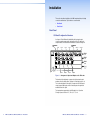
Setup Guide
Matrix Switchers
DMS 1600, DMS 2000,
DMS 3200, DMS 3600
Configurable Digital Video Matrix Switchers
68-1829-50 Rev. C
09 13
Safety Instructions
Safety Instructions • English
WARNING: This symbol, , when used on the product, is intended
to alert the user of the presence of uninsulated dangerous voltage
within the product’s enclosure that may present a risk of electric
shock.
ATTENTION: This symbol, , when used on the product, is
intended to alert the user of important operating and maintenance
(servicing) instructions in the literature provided with the
equipment.
For information on safety guidelines, regulatory compliances, EMI/EMF
compatibility, accessibility, and related topics, see the Extron Safety and
Regulatory Compliance Guide, part number 68-290-01, on the Extron
website, www.extron.com.
Instructions de sécurité • Français
AVERTISSEMENT: Ce pictogramme, , lorsqu’il est utilisé sur
le produit, signale à l’utilisateur la présence à l’intérieur du boîtier
du produit d’une tension électrique dangereuse susceptible de
provoquer un choc électrique.
ATTENTION: Ce pictogramme, , lorsqu’il est utilisé sur le produit,
signale à l’utilisateur des instructions d’utilisation ou de maintenance
importantes qui se trouvent dans la documentation fournie avec
le matériel.
Pour en savoir plus sur les règles de sécurité, la conformité à la
réglementation, la compatibilité EMI/EMF, l’accessibilité, et autres sujets
connexes, lisez les informations de sécurité et de conformité Extron, réf.
68-290-01, sur le site Extron, www.extron.fr.
Sicherheitsanweisungen • Deutsch
WARNUNG: Dieses Symbol
auf dem Produkt soll den Benutzer
darauf aufmerksam machen, dass im Inneren des Gehäuses
dieses Produktes gefährliche Spannungen herrschen, die nicht
isoliert sind und die einen elektrischen Schlag verursachen
können.
VORSICHT: Dieses Symbol
auf dem Produkt soll dem Benutzer
in der im Lieferumfang enthaltenen Dokumentation besonders
wichtige Hinweise zur Bedienung und Wartung (Instandhaltung)
geben.
Weitere Informationen über die Sicherheitsrichtlinien,
Produkthandhabung, EMI/EMF-Kompatibilität, Zugänglichkeit und
verwandte Themen finden Sie in den Extron-Richtlinien für Sicherheit
und Handhabung (Artikelnummer 68-290-01) auf der Extron-Website,
www.extron.de.
Instrucciones de seguridad • Español
ADVERTENCIA: Este símbolo, , cuando se utiliza en el
producto, avisa al usuario de la presencia de voltaje peligroso sin
aislar dentro del producto, lo que puede representar un riesgo de
descarga eléctrica.
ATENCIÓN: Este símbolo, , cuando se utiliza en el producto,
avisa al usuario de la presencia de importantes instrucciones
de uso y mantenimiento recogidas en la documentación
proporcionada con el equipo.
Para obtener información sobre directrices de seguridad, cumplimiento
de normativas, compatibilidad electromagnética, accesibilidad y
temas relacionados, consulte la Guía de cumplimiento de normativas
y seguridad de Extron, referencia 68-290-01, en el sitio Web de Extron,
www.extron.es.
FCC Class A Notice
Инструкция по технике
безопасности • Русский
ПРЕДУПРЕЖДЕНИЕ: Данный символ, , если указан
на продукте, предупреждает пользователя о
наличии неизолированного опасного напряжения
внутри корпуса продукта, которое может привести к
поражению электрическим током.
ВНИМАНИЕ: Данный символ, , если указан на
продукте, предупреждает пользователя о наличии
важных инструкций по эксплуатации и обслуживанию в
руководстве, прилагаемом к данному оборудованию.
Для получения информации о правилах техники
безопасности, соблюдении нормативных требований,
электромагнитной совместимости (ЭМП/ЭДС), возможности
доступа и других вопросах см. руководство по безопасности
и соблюдению нормативных требований Extron на сайте
Extron: www.extron.ru, номер по каталогу - 68-290-01.
This equipment has been tested and found to comply with the limits for a
Class A digital device, pursuant to part 15 of the FCC rules. The Class A
limits provide reasonable protection against harmful interference when
the equipment is operated in a commercial environment. This equipment
generates, uses, and can radiate radio frequency energy and, if not
installed and used in accordance with the instruction manual, may cause
harmful interference to radio communications. Operation of this equipment
in a residential area is likely to cause interference; the interference must be
corrected at the expense of the user.
NOTE: For more information on safety guidelines, regulatory
compliances, EMI/EMF compatibility, accessibility, and related
topics, see the “Extron Safety and Regulatory Compliance
Guide” on the Extron website.
Chinese Simplified(简体中文)
警告:
产品上的这个标志意在警告用户该产品机壳内有暴露的危险
电压,有触电危险。
注 意:
产品上的这个标志意在提示用户设备随附的用户手册中有
重要的操作和维护(维修)说明。
关于我们产品的安全指南、遵循的规范、EMI/EMF 的兼容性、无障碍
使用的特性等相关内容,敬请访问 Extron 网站 www.extron.cn,参见
Extron 安全规范指南,产品编号 68-290-01。
Chinese Traditional(
警告:
)
若產品上使用此符號,是為了提醒使用者,產品機殼內存在著
可能會導致觸電之風險的未絕緣危險電壓。
注意
若產品上使用此符號,是為了提醒使用者。
有關安全性指導方針、法規遵守、EMI/EMF 相容性、存取範圍和相關
主題的詳細資訊,請瀏覽 Extron 網站:www.extron.cn,然後參閱
《Extron 安全性與法規遵守手冊》,準則編號 68-290-01。
Japanese
警告: この記号
が製品上に表示されている場合は、筐体内に絶
縁されて いない高電圧が流れ、感電の危険があることを
示しています。
注意: この記号
が製品上に表示されている場合は、本
機の取扱説明書に 記載されている重要な操作と保
守(整備)の指示についてユーザーの 注意を喚起する
ものです。
安全上のご注意、法規厳守、EMI/EMF適合性、その他の関連項目に
ついては、エクストロンのウェブサイト www.extron.jp より『Extron
Safety and Regulatory Compliance Guide』(P/N 68-290-01) をご覧く
ださい。
Korean
경고: 이 기호 , 가 제품에 사용될 경우, 제품의 인클로저 내에 있는
접지되지 않은 위험한 전류로 인해 사용자가 감전될 위험이
있음을 경고합니다.
주의:
이 기호 , 가 제품에 사용될 경우, 장비와 함께 제공된
책자에 나와 있는 주요 운영 및 유지보수(정비) 지침을
경고합니다.
안전 가이드라인, 규제 준수, EMI/EMF 호환성, 접근성, 그리고 관련
항목에 대한 자세한 내용은 Extron 웹 사이트(www.extron.co.kr)의
Extron 안전 및 규제 준수 안내서, 68-290-01 조항을 참조하십시오.
FDA/IEC 60825-1 Requirements
CLASS 1 LASER PRODUCT
Complies with FDA performance standards for laser products except for
deviations pursuant to Laser Notice No. 5, dated June 24, 2007.
The product is intended to be used with the fiber optic cables fully installed.
This product meets the applicable requirements of IEC 60825-1, Edition 1
(2007).
Any service to this product must be carried out by Extron Electronics and
its qualified service personnel.
Conventions Used in this Guide
Notifications the following are used:
WARNING: A warning indicates a situation that has the potential
to result in death or severe injury.
ATTENTION:
Attention indicates a situation that may damage or
destroy the product or associated equipment.
NOTE: A note draws attention to important information.
Software Commands
Commands are written in the fonts shown here:
Contents
^AR Merge Scene,,Op1 scene 1,1 ^B 51 ^W^C
[01] R 0004 00300 00400 00800 00600 [02] 35 [17] [03]
E Y! *Y1&* Y2)* Y2#* Y2! CE}
NOTE: For commands and examples of computer or device
responses mentioned in this guide, the character “0” is used for
the number zero and “O” is the capital letter “o.”
Computer responses and directory paths that do not have variables are
written in the font shown here:
Reply from 208.132.180.48: bytes=32 times=2ms TTL=32
C:\Program Files\Extron
Variables are written in slanted form as shown here:
ping xxx.xxx.xxx.xxx —t
SOH R Data STX Command ETB ETX
Selectable items, such as menu names, menu options, buttons, tabs, and
field names are written in the font shown here:
From the File menu, select New.
Click the OK button.
Specifications Availability
Product specifications are available on the Extron website,
www.extron.com.
Copyright
© 2013 Extron Electronics. All rights reserved.
Trademarks
All trademarks mentioned in this guide are the properties of their respective owners.
The following registered trademarks®, registered service marks(SM), and trademarks(TM) are
the property of RGB Systems, Inc. or Extron Electronics:
Registered Trademarks (®)
AVTrac, Cable Cubby, CrossPoint, eBUS, EDID Manager, EDID Minder, Extron, Flat Field,
GlobalViewer, Hideaway, Inline, IP Intercom, IP Link, Key Minder, LockIt, MediaLink,
PlenumVault, PoleVault, PowerCage, PURE3, Quantum, SoundField, SpeedMount, SpeedSwitch,
System Integrator, TeamWork, TouchLink, V‑Lock, VersaTools, VN‑Matrix, VoiceLift, WallVault,
WindoWall, XTP and XTP Systems
Introduction...................................... 1
Remote Control............................... 13
About this Guide............................ 1
About the DMS Matrix Switchers... 2
Configurability............................ 3
Configurability rules.................... 3
Selected SIS Commands............. 13
Establishing a Network
(Ethernet) Connection............. 13
Number of connections............ 14
Establishing a USB Port
Connection.............................. 14
Host-to-Switcher Instructions.. 14
Common SIS Command
Symbols.................................. 14
Command and Response
Table for SIS Commands........ 15
Command and Response
Table for IP-Specific SIS
Commands.............................. 20
Installing and Starting the
Control Program......................... 21
Installing the Program.............. 21
First-time Connection
Considerations........................ 22
Starting the Program................ 23
Accessing the HTML Pages......... 25
Configuring for Network
Communication....................... 25
Loading the Start-up Page....... 26
Installation........................................ 5
Rear Panel...................................... 5
I/O Board Configuration
Overview................................... 5
Making Connections.................. 7
Front Panel..................................... 9
Front Panel Operations.................... 11
Creating a Tie............................... 11
Viewing Ties (and Muting
Outputs)...................................... 11
Saving or Recalling a Preset........ 12
Locking Out the Front Panel
(Executive Mode)........................ 12
Maintenance and Modifications....... 29
Removing and Installing an I/O
Board or Blank Panel.................. 29
Removing and Installing a
Power Supply Module
(DMS 1600 and DMS 3600)........ 31
Removing and Installing a Fan
(DMS 1600 and DMS 3600)........ 32
Registered Service Mark(SM) : S3 Service Support Solutions
Trademarks (™)
AAP, AFL (Accu‑Rate Frame Lock), ADSP (Advanced Digital Sync Processing), AIS (Advanced
Instruction Set), Auto‑Image, CDRS (Class D Ripple Suppression), DDSP (Digital Display Sync
Processing), DMI (Dynamic Motion Interpolation), Driver Configurator, DSP Configurator, DSVP
(Digital Sync Validation Processing), FastBite, FOXBOX, IP Intercom HelpDesk, MAAP, MicroDigital,
ProDSP, QS‑FPC (QuickSwitch Front Panel Controller), Scope‑Trigger, SIS, Simple Instruction Set,
Skew‑Free, SpeedNav, Triple‑Action Switching, XTRA, ZipCaddy, ZipClip
DMS 1600, DMS 2000, DMS 3200, DMS 3600 • Contents
v
Introduction
WARNING: Risk of serious physical injury — The DMS fiber
optic I/O boards output continuous invisible light, which may be
harmful to the eyes; use with caution.
• Do not look into the fiber optic cable connectors or into the
fiber optic cables themselves.
• Plug the attached dust caps into the optical transceivers when
the fiber cable is unplugged.
This section gives an overview of this guide and the DMS 1600, DMS
2000, DMS 3200, and DMS 3600 and describes their features. Topics
that are covered include:
•• About this Guide
•• About the DMS Matrix Switchers
About this Guide
NOTES:
• For more information on any subject in this guide, see the DMS
Series Matrix Switcher User Guide, available on the Extron DVD
or at www.extron.com.
• Throughout this guide, all of the covered switchers are referred
to as "DMS matrix switchers" unless a significant difference is
noted in their features or operation.
This setup guide helps you to easily and quickly set up and configure
your Extron DMS matrix switcher. Step by step instructions show you
how to:
•• Install the input and output boards.
•• Connect the hardware.
•• Perform basic operations
•• Use both the front panel controls and selected
Simple Instruction Set commands.
•• Load and start the Matrix Switchers Control Program.
•• Connect to the built-in HTML pages, which you can use to operate
the switcher.
•• Reconfigure the switcher by adding or removing boards, power
supplies, and fans.
vi
DMS 1600, DMS 2000, DMS 3200, DMS 3600 • Contents
DMS 1600, DMS 2000, DMS 3200, DMS 3600 • Introduction
1
About the DMS Matrix Switchers
Configurability
The DMS 1600, DMS 2000, DMS 3200, and DMS 3600 (see figure 1)
are configurable matrix switchers that distribute DVI signals and DFX
transmitter and receiver outputs and inputs. I/O boards route signals
that are compatible with all Extron DVI video product lines and the
fiber optic outputs and inputs of DFX transmitters and receivers. The
matrix switcher routes any input signal to any combination of outputs.
The matrix switcher can route multiple input/output configurations
simultaneously.
1-4
A
B
DVI-D INPUTS
C
D
A
B
DVI-D OUTPUTS
C
B
A
B
C
D
A
B
17 - 20
A
B
21 - 24
A
B
A
B
A
B
A
B
A
B
A
B
5-8
A
D
25 - 28
B
9 - 12
D
C
29- 32
A
13- 16
C
33 - 36
DVI Equipped
PCs
Compact HDTV
Camera Systems
FAN ASSEMBLY
HD Camera
FOXBOX Rx DVI
DISCONNECT BOTH POWER
CORDS BEFORE SERVICING
DVI-D INPUTS
DVI-D INPUTS
DVI-D OUTPUTS
DVI-D OUTPUTS
DVI-D OUTPUTS
DVI-D OUTPUTS
DVI-D OUTPUTS
DVI-D OUTPUTS
DVI-D OUTPUTS
DVI-D OUTPUTS
C
D
C
D
C
D
C
D
C
D
C
D
C
D
C
D
REMOTE
LAN
RS232/RS422
ACT LINK
PRIMARY POWER SUPPLY
HDTV Monitors
MODE
ON
POWER
12V
1.0A MAX
DVI-D
MODE
Digital Monitors
DVI Projectors
RESET
REDUNDANT POWER SUPPLY
Tx Rx
Tx Rx
FOXBOX 4G Tx DVI
1 2
FOXBOX Tx DVI
MODE
ON
DVI-D OUTPUT
POWER
12V
1.0A MAX
DVI-D INPUT
AUDIO
RS-232
OVER FIBER ALARM
AUDIO
There are six types of I/O boards available:
•• 4x4 DVI inputs and outputs
• 4x4 fiber inputs and outputs
•• 4 DVI inputs
• 4 fiber inputs
•• 4 DVI outputs
• 4 fiber outputs
•• DMS Matrix 1600 — A 16-input by 16-output matrix
•• DMS Matrix 2000 — A 20-input by 20-output matrix
•• DMS Matrix 3600 — A 36-input by 36-output matrix
PRIMARY
1 2
100-240V
50/60Hz
1.2A MAX.
ANAHEIM, CA
POWER
12V
1.0A MAX
•• The DMS 3600 can include up to nine I/O boards.
Configurability rules
OVER OVER
FIBER
ALARM
FIBERALARM
FOXBOX 4G Rx DVI
•• The DMS 3200 can include up to eight I/O boards.
•• DMS Matrix 3200 — A 32-input by 32-output matrix
100-240V
50/60Hz
1.2A MAX.
INPUTDVI-D OUTPUT AUDIO AUDIORS-232
RS-232
1 2
•• The DMS 2000 can include up to five I/O boards.
By adding or removing I/O boards within certain rules that are detailed
in "Configurability rules," below, you can expand and contract each
switcher model from a 4-input by 4-output matrix to up to:
REDUNDANT
POWER
12V
1.0A MAX
•• The DMS 1600 can include up to four I/O boards.
D
FAN ASSEMBLY
DVI-D INPUTS
The DMS matrix switchers are assembled from I/O boards.
Extron
DMS 3600
Analog Monitor
There are certain rules for configuring the DMS matrix switcher for proper
operation, as detailed below:
•• The top slot (slot 1) MUST contain a 4x4 DVI or fiber optic input and
Modular DVI Matrix Switcher
RS-232
OVER FIBER ALARM
output board.
1 2
Tx Rx
1 2
FOXBOX 4G
Rx DVI
FOXBOX
4G Tx DVI Tx Rx
1 2
•• The next slot (slot 2) can contain any of the six board types.
•• A 4x4 input and output board can be followed (in the slot directly
ADJUST
INPUTS
1
CONFIG
2
3
4
5
6
MUTE
AUTO
IMAGE
SIZE
BRIGHT
/CONT
DETAIL
MENU
FREEZE
PIP
PRESET
POSITION
COLOR
/TINT
ZOOM
/PAN
NEXT
7
UPS 507
underneath it) by any of the board types.
UNVERSAL SIGNAL PROCESSOR
PC
Figure 1.
USP 507
Typical DMS 3600 Application
Each matrix switcher model can be remotely controlled via its Ethernet
LAN port, a serial port, or a USB port using either the Windows-based
Extron Matrix Switchers Control Program or the SIS.
The switcher has two internal, hot-swappable 100 VAC to 240 VAC,
50-60 Hz, 175-watt power supplies that provide worldwide power
compatibility and reliability.
2
DMS 1600, DMS 2000, DMS 3200, DMS 3600 • Introduction
•• After you insert a 4-input board or a 4-output board, all active boards
underneath it MUST be the same size (4 inputs or 4 outputs).
•• Fiber boards can follow DVI boards and DVI boards can follow fiber
boards within the above size rules.
•• If you install a blank panel, all slots under it MUST contain blank
panels (you cannot skip a slot).
DMS 1600, DMS 2000, DMS 3200, DMS 3600 • Introduction
3
Installation
This section describes installation of the DMS matrix switchers, including
connections and features. Topics that are covered include:
•• Rear Panel
•• Front Panel
Rear Panel
I/O Board Configuration Overview
See figure 2. Each I/O board is identified by the input and output
connector numbers supported by the board position. The input and
output numbers on the boards are identified as locations A through D.
Location A
Input
Location A
Input 1
1-4
A
Input 2
Input 3
DVI-D INPUTS
B
Output
Input 4
C
D
Output 1
A
Output 2
B
DV
Slot 1
(1-4)
ANAHEIM, CA
5-8
A
DVI-D INPUTS
B
C
D
Slot 2
(5-8)
B
9 - 12
A
C
D
Slot 3
TMDS
FIBER
INPUTS
13 - 16
(9-12)
Slot 4
100-240V
Input 5
Figure 2.
No board
installed
PRIMARY POWER SUPPLY
50/60Hz 1.2A MAX.
Input 6
Input 7
Input 8
Arrangement of Inputs and Outputs on the I/O boards
The board position designators correspond to the input and output
numbers served by that position (1 through 4, 5 through 8, and so on).
The location designators, A through D, correspond to the DVI input or
output, grouped with inputs on the left and outputs on the right and
numbered from left to right.
The input numbers supported by the I/O board in slot 2 (locations
5 through 8) are as follows: A = 5, B = 6, C = 7, D = 8.
4
DMS 1600, DMS 2000, DMS 3200, DMS 3600 • Introduction
DMS 1600, DMS 2000, DMS 3200, DMS 3600 • Installation
5
1-4
A
B
2
DVI-D INPUTS
C
D
A
B
DVI-D OUTPUTS
C
D
A
B
TMDS
FIBER
INPUTS
TMDS
FIBER
OUTPUTS
DMS FIBER 44
D
13 - 16
DMS FIBER 44
C
B
B
A
B
A
B
A
B
A
B
DVI-D INPUTS
C
D
A
B
C
D
A
B
C
D
A
B
C
D
A
B
DVI-D OUTPUTS
C
D
C
D
C
D
C
D
DMS 44 DVI
DVI-D INPUTS
DVI-D OUTPUTS
DMS 44 DVI
TMDS
FIBER
INPUTS
A
A
FAN ASSIMBLY
9 - 12
C
D
D
DVI-D INPUTS
DVI-D OUTPUTS
DMS 44 DVI
TMDS
FIBER
INPUTS
13- 16
B
9 - 12
A
C
5-8
C
B
5-8
A
2
D
DMS 44 DVI
ANAHEIM, CA
1
10
1-4
1
10
DMS FIBER 44
DVI-D INPUTS
DVI-D OUTPUTS
17 - 20
A
FAN ASSIMBLY
PRIMARY POWER SUPPLY
B
REDUNDANT POWER SUPPLY
A
9
3
A
B
DVI-D INPUTS
C
D
A
B
DVI-D OUTPUTS
B
B
33 - 36
C
D
A
B
RESET
B
D
A
B
C
D
A
B
A
B
A
B
TMDS
FIBER
INPUTS
9 - 12
LAN
5-8
A
C
TMDS
FIBER
INPUTS
DISCONNECT BOTH POWER
CORDS BEFORE SERVICING
C
D
C
D
C
D
Figure 4.
LAN
RS232/RS422
ACT LINK
RESET
REDUNDANT POWER SUPPLY
PRIMARY
DMS FIBER 44
D
PRIMARY POWER SUPPLY
100-240V
50-60Hz
2.5A MAX.
D
C
100-240V
50-60Hz
2.5A MAX.
ANAHEIM, CA
DMS FIBER 44
C
TMDS
FIBER
OUTPUTS
3
REMOTE
REDUNDANT
DMS FIBER 44
TMDS
FIBER
OUTPUTS
8
D
C
TMDS
FIBER
OUTPUTS
17 - 20
100-240V
50/60Hz
2.0A MAX
C
TMDS
FIBER
OUTPUTS
13- 16
5
B
D
DMS FIBER 44
D
N
A
DMS FIBER 44
C
TMDS
FIBER
INPUTS
DMS 44 DVI
REMOTE
7
6
D
TMDS
FIBER
OUTPUTS
1-4
A
2
C
TMDS
FIBER
INPUTS
A
1
B
TMDS
FIBER
INPUTS
9
4
DMS 1600 Features
A
TMDS
FIBER
OUTPUTS
C
B
25 - 28
8
Figure 3.
D
TMDS
FIBER
INPUTS
29- 32
7
C
TMDS
FIBER
INPUTS
21 - 24
RESET
RS-232/RS-422
DISCONNECT BOTH POWER
CORDS BEFORE SERVICING
LAN
6
PRIMARY
100-240V
50-60Hz
1.2A MAX.
ACT
5
LINK
REMOTE
DMS 44 DVI
REDUNDANT
100-240V
50-60Hz
1.2A MAX.
D
8
9
3
4
5
6 7
9
DMS FIBER 44
Figure 6.
4
DMS 3600 Features
Making Connections
DMS 2000 Features
1
3
a DVI-I Input connectors — Connect DVI cables between these
4
ports and the DVI output ports of the digital video sources.
B
A
B
1-4
A
D
A
B
C
D
A
B
C
D
A
B
9 - 12
17 - 20
A
B
21 - 24
A
B
A
DVI-D INPUTS
DMS FIBER 44
D
A
B
C
D
A
B
C
D
A
B
DVI-D OUTPUTS
DMS FIBER 44
c Fiber optic input ports — Connect fiber optic cables to the
D
DMS FIBER 44
C
D
C
D
C
D
DMS 44 DVI
DVI-D INPUTS
DVI-D OUTPUTS
Input LC connectors.
Connect the opposite ends of these fiber optic cables to the Output
connectors on DFX 100 Tx transmitters.
Input LEDs — These LEDs light amber to indicate fiber connections.
These LEDs light green to indicate signal detection.
DMS 44 DVI
B
DVI-D INPUTS
C
D
DMS 44 DVI
d Fiber optic output ports — Connect fiber optic cables to the
Input LC connectors.
Connect the opposite ends of these fiber optic cables to the Input
connectors on DFX 100 Rx receivers.
8
1
Figure 5.
6
DVI-D OUTPUTS
29- 32
100-240V
50/60Hz
3.0A MAX
DMS 44 DVI
DVI-D INPUTS
b DVI-I Output connectors — Connect DVI displays for the routed DVI
image.
D
C
TMDS
FIBER
OUTPUTS
C
D
C
TMDS
FIBER
OUTPUTS
TMDS
FIBER
INPUTS
B
C
TMDS
FIBER
OUTPUTS
TMDS
FIBER
INPUTS
A
13- 16
C
TMDS
FIBER
INPUTS
25 - 28
RESET
LAN
6
7
B
5-8
REMOTE
5
A
DMS 3200 Features
DMS 1600, DMS 2000, DMS 3200, DMS 3600 • Installation
2
Input LEDs — These LED light amber to indicate fiber connections.
These LEDs light green to indicate signal transmissions.
DMS 1600, DMS 2000, DMS 3200, DMS 3600 • Installation
7
e Remote port — If desired, connect a control system or computer to
Front Panel
the rear panel Remote RS-232/RS-422 port.
5
9
Figure 7.
1
6
Pin RS-232 Function RS-422 Function
1
— Not used
—
Not used
2
Tx Transmit
Tx– Transmit (–)
3
Rx Receive
Rx– Receive (–)
4
— Not used
—
Not used
5
Gnd Ground
Gnd Ground
6
— Not used
—
Not used
7
— Not used
Rx+ Receive (+)
8
— Not used
Tx+ Transmit (+)
9
— Not used
—
Not used
Remote RS-232/RS-422 Output Connector Wiring
f Ethernet port (LAN connector) — If desired, connect a network
WAN or LAN hub, a control system, or a computer to the Ethernet
RJ-45 port.
Network connection — Use a patch (straight-through) cable.
Computer or control system connection — Use a crossover
cable.
NOTE:
CONTROL
CONFIG
ENTER
PRESET
VIEW
ESC
CONTROL
PRIMARY
CONFIG
ENTER
REDUNDANT
PRESET
VIEW
ESC
POWER
POWER SUPPLY
DMS 1600
DMS 2000
TMDS DIGITAL MATRIX SWITCHER
1
2
Figure 8.
TMDS DIGITAL MATRIX SWITCHER
1
3
Front Panel Features
a Configuration port — If desired, connect a control system or
computer to the front panel Configuration port, a mini USB B port.
b Primary and Redundant Power Supply LEDs
(DMS 1600 and DMS 3600) —
NOTE: The meaning of these indicators is identical to the LEDs
on the power supplies (item i, on the previous page).
The factory default IP address is 192.168.254.254.
g Reset button — Initiates four levels of reset of the matrix switcher.
For different reset levels, press and hold the recessed button while
the switcher is running or while you power up the switcher.
See the DMS Series Matrix Switcher User Guide, available on the
Extron DVD or at www.extron.com.
h Power connectors — Plug the switcher into one or two (depending
on the DMS model) grounded AC sources.
NOTE: For reliability in switchers with Primary and Redundant
power supplies, connect the power cord from the Redundant
power connector to either an uninterruptible power source or to
a power source that is completely independent of the primary
power source.
Green — Indicates that the associated power supply is operating
within normal tolerances.
Red — Indicates that the associated power supply is operating
outside the normal tolerances or has failed (see Removing and
Installing a Power Supply Module (DMS 1600 and DMS 3600) on
page 31 to replace the power supply).
c Power LED (DMS 2000 and DMS 3200)— Indicates that the
power supply is operating within normal tolerances.
NOTE: The power supply is fixed, and not field replaceable, on
the DMS 2000 and DMS 3200.
i Primary and Redundant power supply indicator LEDs
(DMS 1600 and DMS 3600) —
Green — Indicates that the associated power supply is operating
within normal tolerances.
Red — Indicates that the associated power supply is operating
outside the normal tolerances or has failed (see Removing and
Installing a Power Supply Module (DMS 1600 and DMS 3600) on
page 31 to replace the power supply).
j Fans (DMS 1600 and DMS 3600) — See Removing and
Installing a Fan (DMS 1600 and DMS 3600) on page 32.
8
DMS 1600, DMS 2000, DMS 3200, DMS 3600 • Installation
DMS 1600, DMS 2000, DMS 3200, DMS 3600 • Installation
9
Front Panel Operations
This section describes simple DMS matrix switcher operation from the
front panel. Topics that are covered include:
•• Creating a Tie
•• Viewing Ties (and Muting Outputs)
•• Saving or Recalling a Preset
•• Locking Out the Front Panel (Executive Mode)
Creating a Tie
A "tie" is an input-to-output connection.
A "set of ties" is an input tied to two or more outputs. (An output can
never be tied to more than one input.)
A "configuration" is one or more ties, one or more sets of ties, or a
combination.
1. Press and release the Esc button to clear any input button, output
button, or control button indicators that may be lit.
2. Press and release the desired input button.
The button lights to indicate the selection.
5
3. Press and release the desired output buttons.
The output buttons blink to indicate the potential ties.
3
4
8
ENTER
The Enter button blinks to indicate
the need to confirm the change.
4. Press and release the Enter button. All button indicators turn off.
Viewing Ties (and Muting Outputs)
1. Press the View button. Output buttons light for outputs that have no
ties established.
NOTE: If an output button blinks, that output is muted. To
toggle mute on and off, press and hold the output button for 2
seconds.
2. Press an input button. The buttons for all tied outputs light.
10
DMS 1600, DMS 2000, DMS 3200, DMS 3600 • Installation
DMS 1600, DMS 2000, DMS 3200, DMS 3600 • Front Panel Operations
11
3. Press an output button. The buttons for the tied input and all tied
outputs light.
Remote Control
4. Press the View button again to exit View mode. All input and output
buttons return to an unlit state.
Saving or Recalling a Preset
The DMS switchers have 32 global memory presets.
This section describes using the remote control features of the
DMS matrix switchers to control the devices. Topics that are covered
include:
1. Save a preset — Press and hold the Preset button until it flashes.
•• Selected SIS Commands
Save a
preset
PRESET
•• Installing and Starting the Control Program
2 seconds
PRESET
•• Accessing the HTML Pages
The Preset button blinks.
Press and hold.
Recall a preset — Press and release the Preset button.
Recall a
preset
PRESET
You can use Simple Instruction Set (SIS) commands for operation and
configuration of the switchers. You can run these commands from a PC
connected to a serial port (item e on page 8), Ethernet port (item f on
page 8), or USB port (item a on page 9) on the switcher.
PRESET
Press and release.
Selected SIS Commands
The Preset button lights.
All input and output buttons with assigned presets light red.
When a preset is saved, the configuration data at
assigned preset locations will be overwritten.
Establishing a Network (Ethernet) Connection
INPUTS
1
2
3
4
5
NOTE: The first time you connect to the switcher via the LAN port,
you may need to change the default settings (IP address, subnet
mask, and [optional] administrator password) of the switcher.
6 15 16
2. Press and release the desired input or output button.
Establish a network connection as follows:
The button blinks red to indicate that
this preset is selected to save or recall.
1
ENTER
1. Open a TCP socket to port 23 using the IP address of the switcher.
NOTE:
The Enter button blinks
red to indicate the need to
activate the save or recall.
The switcher responds with a copyright message including the name,
firmware version, and part number of the product, and the current
date and time.
3. Press and release the Enter button.
Locking Out the Front Panel (Executive Mode)
NOTES:
To toggle the front panel lock on and off, simultaneously press and hold
the Enter button and the Esc button until the Preset and View buttons
blink twice (approximately 2 seconds).
Press and hold the Enter and
Esc buttons simultaneously to
toggle executive mode on or off.
C O NT R O L
ENTER PRESET
VIEW
2 seconds
• If the switcher is not password-protected, the device is now
ready to accept SIS commands.
• If the switcher is password-protected, a password prompt
appears.
2. If necessary, enter the appropriate password.
C O NT R O L
ESC
The factory default IP address is 192.168.254.254.
ENTER PRESET
VIEW
ESC
If the password is accepted, the switcher responds with Login User
or Login Administrator.
If the password is not accepted, the Password prompt reappears.
The Preset and View buttons
blink twice to indicate the
mode change.
Release the buttons.
12
DMS 1600, DMS 2000, DMS 3200, DMS 3600 • Front Panel Operations
DMS 1600, DMS 2000, DMS 3200, DMS 3600 • Remote Control
13
Number of connections
A switcher can have up to 200 simultaneous TCP connections, including
all HTTP sockets and Telnet connections. When the connection limit is
reached, the switcher accepts no new connections until some have been
closed. No error message or indication is given that the connection limit
has been reached. To maximize the performance of your switcher, keep
the number of connections low and close unnecessary open sockets.
14
DMS 1600, DMS 2000, DMS 3200, DMS 3600 • Remote Control
• = Space
X! = Input number
X@ = Output number
NOTE:
Read output tie
00 – maximum number of inputs for your configuration (00 = untied)
01 – maximum number of outputs for your configuration
Input X! is tied to output X@.
Input X! is tied to output X@.
Input X! is tied to output X@.
X!]
X!]
X!]
X@&
X@%
X@!
Read output tie
Tie input 7 to output 5.
Read output tie
Tie input X! to output X@.
Out05•In07•Vid]
7*5%
Example (see Notes, above):
Tie input 10 to output 4.
OutX@•InX!•Vid]
X!*X@%
Tie input 1 to output 3.
Out03•In01•All]
1*3!
Tie input X! to output X@
Tie input X! to output X@.
OutX@•InX!•All]
X!*X@!
(Unit to Host)
Response
(Host to Unit)
Tie input X! to output X@.
W = Can be used interchangeable with the E character
Out04•In10•RGB]
= Pipe (can be used interchangeably with the } character)
E = Escape key (hex 1B)
10*4&
|
OutX@•InX!•RGB]
= Space
] = Carriage return and line feed
} = Carriage return (no line feed)
X!*X@&
•
Tie input X! to output X@
Example (see Notes, above):
The following symbols are used throughout the command and response
table, which starts on the next page:
Tie input X! to output X@
Example (see Notes, above):
Common SIS Command Symbols
ASCII Command
NOTE: The table that begins on the next page is a partial list
of SIS commands. For a complete listing, see the DMS Series
Matrix Switcher User Guide, available on the Extron DVD or at
www.extron.com.
Command
The switcher accepts SIS commands through its serial port, its USB port,
or its LAN port. SIS commands consist of one or more characters per
command field. They do not require any special characters to begin or
end the command character sequence. Each switcher response to an
SIS command ends with a carriage return and a line feed (CR/LF = ]),
which signals the end of the response character string. A string is one or
more characters.
Command and Response Table for SIS Commands
Host-to-Switcher Instructions
NOTES:
•The ! tie command, the & tie command, and the % tie command can be used interchangeably.
•The ! read tie command, & read tie command, and the % read tie command can be used interchangeably.
NOTE: Before you use the USB port for the first time, install the
USB driver on your computer. The simplest way to do this is to
install version 8.0 or newer of the Matrix Switchers Control Program
and then run the Found New Hardware Wizard (see Installing the
Program on page 21 and First-time Connection Considerations
on page 22).
Create ties
Additional Description
A standard USB cable and the Extron DataViewer utility, version 2.0
or newer, can be used for connection to the DMS matrix switcher
Configuration port. The USB cable, available at any local electronics
store, should be terminated on one end with a mini USB B male
connector
NOTES:
• Commands can be entered back-to-back in a string, with no spaces. For example: 1*1!02*02&003*003%.
• The matrix switchers support 1-, 2-, and 3-digit numeric entries (1*1!, 02*02&, or 003*003%).
Establishing a USB Port Connection
DMS 1600, DMS 2000, DMS 3200, DMS 3600 • Remote Control
15
Command and Response Table for SIS Commands
Command
ASCII Command
(Host to Unit)
Response
(Unit to Host)
Additional Description
NOTES:
• Commands can be entered back-to-back in a string, with no spaces. For example: 1*1!02*02&003*003%.
• The matrix switchers support 1-, 2-, and 3-digit numeric entries (1*1!, 02*02&, or 003*003%).
Create ties
DMS 1600, DMS 2000, DMS 3200, DMS 3600 • Remote Control
NOTES:
•The ! tie command, the & tie command, and the % tie command can be used interchangeably.
•The ! read tie command, & read tie command, and the % read tie command can be used interchangeably.
Tie input X! to output X@
Example (see Notes, above):
X!*X@!
OutX@•InX!•All]
Tie input X! to output X@.
1*3!
Out03•In01•All]
Tie input 1 to output 3.
Tie input X! to output X@
Example (see Notes, above):
X!*X@&
OutX@•InX!•RGB]
Tie input X! to output X@.
10*4&
Out04•In10•RGB]
Tie input 10 to output 4.
Tie input X! to output X@
X!*X@%
OutX@•InX!•Vid]
Tie input X! to output X@.
7*5%
Out05•In07•Vid]
Tie input 7 to output 5.
X@&
X@%
X@!
X!]
X!]
X!]
Input X! is tied to output X@.
Example (see Notes, above):
Read output tie
Read output tie
Read output tie
NOTE:
• = Space
X! = Input number
X@ = Output number
Input X! is tied to output X@.
Input X! is tied to output X@.
00 – maximum number of inputs for your configuration (00 = untied)
01 – maximum number of outputs for your configuration
15
16
Command
ASCII Command
Response
DMS 1600, DMS 2000, DMS 3200, DMS 3600 • Remote Control
(Host to Unit)
Additional Description
(Unit to Host)
EDID
NOTE: In the commands below, the EDID data can come from either an active output or be set to a specified value.
Assign EDID data to an input
Assign EDID data to all inputs
Save output #1 EDID data to a
user-defined space
View EDID data assignment
EAX!*X#EDID}
EA*X#*EDID}
ES*X#EDID}
EdidAX!*X#]
EdidA0*X#]
EdidSX#]
X! = Input number
EA*X!EDID}
X#]
X! = Input number
X# (EDID) values:
X# value for DMS model
1600
2000
3200
3600
01
01
01
01
02
02
02
03
03
03
04
04
05
05
06
07
Source
X# value for DMS model
1600
2000
3200
3600
Output 1
13
13
13
13
02
Output 2
14
14
14
03
Output 3
15
15
15
04
04
Output 4
16
16
05
05
Output 5
N/A
17
06
06
06
Output 6
N/A
07
07
07
Output 7
N/A
08
08
08
08
Output 8
09
09
09
09
Output 9
10
10
10
10
11
11
11
11
12
12
12
12
2000
3200
3600
Output 13
N/A
N/A
25
25
Output 25
14
Output 14
N/A
N/A
26
26
Output 26
15
Output 15
N/A
N/A
27
27
Output 27
16
16
Output 16
N/A
N/A
28
28
Output 28
17
17
Output 17
N/A
N/A
29
29
Output 29
18
18
18
Output 18
N/A
N/A
30
30
Output 30
19
19
19
Output 19
N/A
N/A
31
31
Output 31
N/A
20
20
20
Output 20
N/A
N/A
32
32
Output 32
N/A
N/A
21
21
Output 21
N/A
N/A
N/A
33
Output 33
Output 10
N/A
N/A
22
22
Output 22
N/A
N/A
N/A
34
Output 34
Output 11
N/A
N/A
23
23
Output 23
N/A
N/A
N/A
35
Output 35
Output 12
N/A
N/A
24
24
Output 24
N/A
N/A
N/A
36
Output 36
ASCII Command
(Host to Unit)
X# (EDID) values (continued):
X# value for DMS model
2000
3200
3600
17
21
33
37
18
22
34
38
Resolution
Response
Additional Description
(Unit to Host)
X# value for DMS model
Resolution
1600
2000
3200
3600
640x480 @ 60 Hz
32
36
48
52
1365x768 @ 75 Hz
640x480 @ 75 Hz
33
37
49
53
1366x768 @ 60 Hz
DMS 1600, DMS 2000, DMS 3200, DMS 3600 • Remote Control
19
23
35
39
800x600 @ 60 Hz
34
38
50
54
1366x768 @ 75 Hz
20
24
36
40
800x600 @ 75 Hz
35
39
51
55
1400x1050 @ 60 Hz
21
25
37
41
852x480 @ 60 Hz
36
40
52
56
1600x1200 @ 60 Hz
22
26
38
42
852x480 @ 75 Hz
37
41
53
57
1920x1200 @ 60 Hz
23*
27*
39*
43*
1024x768 @ 60 Hz
38
42
54
58
480p @ 60 Hz
24
28
40
44
1024x768 @ 75 Hz
39
43
55
59
576p @ 50 Hz
25
29
41
45
1024x852 @ 60 Hz
40
44
56
60
720p @ 50 Hz
26
30
42
46
1024x852 @ 75 Hz
41
45
57
61
720p @ 60 Hz
27
31
43
47
1280x768 @ 60 Hz
42
46
58
62
1080p @ 60 Hz
28
32
44
48
1280x768 @ 75 Hz
43
47
59
63
1080i @ 60 Hz
29
33
45
49
1280x1024 @ 60 Hz
44
48
60
64
1080p @ 50 Hz
30
34
46
50
1280x1024 @ 75 Hz
45
49
61
65
1080p @ 60 Hz, stereo
31
35
47
51
1365x768 @ 60 Hz
46–53
50–57
62–69
66–73
User defined
* = Default setting
Source
1600
Command
1600
X# value for DMS model
Source
17
18
Command
DMS 1600, DMS 2000, DMS 3200, DMS 3600 • Remote Control
Channel mute commands
Channel mute
ASCII Command
(Host to Unit)
Read channel mute
X@*1B
X@*0B
X@B
Global channel mute
1*B
Global channel unmute
0*B
View output mutes
EVM}
Channel unmute
Response
(Unit to Host)
Additional Description
VmtX@*1]
Mute output X@ (no signal is output).
VmtX@*0]
Unmute output X@ (signal is output).
X$]
Vmt1]
Vmt0]
X$1X$2 ... X$n]
1 = mute on, 0 = mute off.
Mute all outputs.
Unmute all outputs.
Each X$ response is the mute status of an output,
starting from output 1.
n = the maximum number of outputs for your
configuration.
Save and recall presets
NOTE: If you try to recall a preset that is not saved, the matrix switcher responds with the error code E11.
Save current configuration as a
global preset
Example:
X%,
Recall a global preset
5.
Example:
NOTE:
SprX%]
Command character is a comma.
9,
Spr09]
Save current ties as preset 9.
X%.
RprX%]
Command character is a period.
Rpr05]
Recall preset 5, which becomes the current
configuration.
X@ = Output number
X$ = Mute status
X% = Global preset number
Command
01 – maximum number of outputs for your configuration
0 = not muted, 1 = muted
01 – 32
ASCII Command
(Host to Unit)
Response
(Unit to Host)
Additional Description
Information requests
DMS 1600, DMS 2000, DMS 3200, DMS 3600 • Remote Control
Information request
I
Request part number
N
Request part number and board
configuration
Query controller firmware
version
Example:
*N
NOTE:
X^ = Inputs
X& = Outputs
X* = Board installed
VX^XX&•A0X0•SX*1X*2...X*n]
In the response:
VX^XX& shows the number of available inputs and
outputs for this configuration.
A0X0 has no meaning for this product.
SX*1X*2...X*n shows the board type installed in each
slot. n is the highest numbered board in your system,
4, 5, 8, or 9.
See the Extron website, www.extron.com, for part
X(]
numbers.
n is the highest numbered board in your system, 4, 5,
X(.X*1X*2X*3...X*n]
8, or 9.
Q
X1)]
Q
1.23]
Total number of inputs for this switcher
Total number of outputs for this switcher
X0 = No board installed
C1 = 4 DVI inputs by 4 DVI outputs
C2 = 4 DVI inputs by 0 outputs
C3 = 0 inputs by 4 DVI outputs
X( = Part number
60-nnnn-nn
X1) = Firmware version number to second decimal place (x.xx)
The factory-installed controller firmware version is
1.23 (sample value only).
F1 = 4 fiber inputs x 4 fiber outputs
F2 = 4 fiber inputs x 0 outputs
F3 = 0 inputs x 4 fiber outputs
19
20
Command and Response Table for IP-Specific SIS Commands
DMS 1600, DMS 2000, DMS 3200, DMS 3600 • Remote Control
Command
IP and serial port setup
Set IP address
Read IP address
Set subnet mask
Read subnet mask
Set gateway IP address
Read gateway IP address
Set DHCP on or off
Read DHCP on/off status
NOTE:
X1! = Address
X1@ = DHCP
ASCII Command
(host to unit)
EX1!CI}
ECI}
EX1!CS}
ECS}
EX1!CG}
ECG}
EX1@DH}
EDH}
Response
IpiX1!]
X1!]
IpsX1!]
X1!]
IpgX1!]
X1!]
IdhX1@]
X1@]
nnn.nnn.nnn.nnn
0 = off, 1 = on
Additional Description
(unit to host)
Default: 192.168.254.254
Default: 255.255.0.0
Default: 0.0.0.0
Default: 0 (Off)
Installing and Starting the Control Program
Another way to operate the switcher is via the Windows®-based Matrix
Switchers Control Program. This program is contained on the Extron
Software Products DVD (included with the switcher) or on the website.
Run this program on a PC connected to a serial port (item e on page 8),
Ethernet port (item f on page 8), or USB port (item a on page 9) on the
switcher. The program must be installed on a Windows-based computer
and cannot be run from the DVD.
NOTE: For details on operating the program see the “Matrix
Software” section in the DMS Series Matrix Switchers User Guide.
Installing the Program
NOTE: To run this program while your computer is connected to
the Configuration (USB) port, use version 8.0 or newer of the Matrix
Switchers Control Program.
1. Insert the DVD into the drive. The Extron software DVD window
should appear automatically.
Figure 9.
Software DVD Window
NOTE: If the window does not open automatically, run
Launch.exe from the DVD.
2. Click the Software tab.
3. Scroll to the Matrix Switchers program and click Install.
Figure 10. Select Matrix Switchers Program
DMS 1600, DMS 2000, DMS 3200, DMS 3600 • Remote Control
21
4. Follow the on-screen instructions. The installation program creates a
C:\Program Files\Extron\Matrix_Switchers directory and an “Extron
Electronics\Matrix Switchers” group folder. It installs the following
four programs:
•• MATRIX Switcher+ Control Program
•• MATRIX Switcher+ Help
•• Uninstall MATRIX Switcher
2. On the next page that appears, select the Install the software
automatically radio button and click Next. Follow the on-screen
instructions. The wizard assigns the driver necessary to access the
switcher to the connected Configuration (USB) port (this may take a
few minutes).
3. Click Finish to exit the wizard.
NOTE: You may need to repeat these steps if you subsequently
connect the switcher to a different USB port on the same
computer.
•• Check for Matrix Updates
First-time Connection Considerations
Starting the Program
LAN port connection
If you connect your PC to the switcher via the LAN port, and it is the first
time you have done so, you may change the default settings (IP address,
subnet mask, and [optional] administrator password) on the controller
(see Configuring for Network Communication on page 25 for details.)
1. Click Start > Programs > Extron Electronics > Matrix
Switchers > MATRIX Switcher + Control Pgm.
The Comm Port Selection window appears.
USB port connection
When you connect your PC to the DMS matrix switcher via the USB port
for the first time, the Found New Hardware Wizard opens.
1
Figure 11. Comm Port selection Window
2. Choose the comm (serial) port that is connected to the switcher, USB,
or IP [LAN].
1
Activate the connected USB port for your device as follows:
NOTE: If you have not installed the latest Matrix Switchers Control
Program, click Cancel and install the program. Reconnect the
switcher to the Configuration port.
1. Select the No, not this time radio button and click Next. The
wizard installs the necessary driver to access the switcher via the
Configuration (USB) port (this may take a few minutes).
22
DMS 1600, DMS 2000, DMS 3200, DMS 3600 • Remote Control
NOTE:
For a comm port, check the baud
rate displayed in the Comm Port Selection
window. If you need to change the baud
rate, click the Baud button and
double-click the desired baud rate.
3. Click OK.
If you selected a serial port or the USB port in step 2, the Matrix
Switchers Control Program is ready for operation.
DMS 1600, DMS 2000, DMS 3200, DMS 3600 • Remote Control
23
4. If you selected IP [LAN] in step 2, the IP Connection window
appears.
Accessing the HTML Pages
Another way to configure and operate the switcher is via its
factory-installed HTML pages, which are always available and cannot
be erased or overwritten. The HTML pages that are pre-loaded on the
switcher are accessible through its LAN port, connected via a LAN or
WAN, using a web browser such as Microsoft® Internet Explorer® (see
item f on page 8, for connection information.)
Configuring for Network Communication
Figure 12. IP Connection Window
a. Examine the Matrix IP Address field, which displays the
last Matrix IP address entered.
If necessary, enter the correct IP address in the field.
NOTE:
192.168.254.254 is the factory-specified default
value for this field.
b. If the switcher is password-protected, enter the appropriate
administrator or user password in the Password field.
The first time you connect a PC to the LAN port of a switcher, you may need
to temporarily change the IP settings of the PC in order to communicate
with the controller. Then you must change the default settings of the
controller (IP address, subnet mask, and [optional] administrator name and
password) in order to use the unit on an intranet (LAN) or on the Internet.
After you have set up the DMS matrix switcher for network communication,
you can reset the PC to its original network configuration.
NOTE: The computer and the switcher must both be connected
to the same subnet on a LAN (using a straight-through cable).
Alternatively, you can use a crossover Ethernet cable to connect
the controller directly to the computer.
c. Click Connect. The Matrix Switchers Control Program is
ready for operation.
Use the ARP command to configure the IP address as follows:
1. Obtain a valid IP address for the DMS matrix switcher from the
network administrator.
2. Obtain the MAC address (UID #) of the switcher from the label
on its rear panel. The MAC address should have this format:
00-05-A6-xx-xx-xx.
3. If the switcher has never been configured and is still set for factory
defaults, go to step 4. If not, perform a mode 4 system reset. For
detailed information on reset modes, see “Reset Operations” in the
DMS Series Matrix Switchers User Guide.
NOTE: The switcher must be configured with the factory default
IP address (192.168.254.254) before the ARP command is
executed, as described below.
4. At the PC, access the MS-DOS® command prompt, then enter the
arp –s command. Type in the desired new IP address for the unit
(see step 1) and the MAC address of the unit (from the rear panel of
the unit). For example (where the new address is 10.13.197.7):
arp –s 10.13.197.7 00-05-A6-03-69-B0 and then press <Enter>.
After receiving the arp -s command, the controller changes to
the new address and starts responding to the ping requests, as
described in step 5.
NOTE:You must ping the DMS matrix switcher as shown in
step 5 for the IP address change to take place. The response
should show the new IP address, as shown in the following figure.
24
DMS 1600, DMS 2000, DMS 3200, DMS 3600 • Remote Control
DMS 1600, DMS 2000, DMS 3200, DMS 3600 • Remote Control
25
5. Execute a ping command by entering ping followed by a space and
the new IP address at the command prompt. For example:
ping 10.13.197.7
C:\>ping 10.13.197.7
Pinging 10.13.197.7 with 32 bytes of data:
Reply
Reply
Reply
Reply
from
from
from
from
10.13.197.7:
10.13.197.7:
10.13.197.7:
10.13.197.7:
bytes=32
bytes=32
bytes=32
bytes=32
time<10ms
time<10ms
time<10ms
time<10ms
TTL=128
TTL=128
TTL=128
TTL=128
4. Press the keyboard <Enter> key. The switcher checks whether it is
password-protected.
If the switcher is not password-protected, it checks and
downloads the HTML start-up page. The switcher is ready for
operation via HTML remote control.
If the switcher is password-protected, it downloads the Enter
Network Password page.
Ping statistics for 10.13.197.7:
Packets: Sent = 4, Received = 4, Lost = 0 (0% loss),
Approximate round trip times in milli-seconds:
Minimum = 0ms, Maximum = 0ms, Average = 0ms
NOTE:
You can reconnect using either Telnet or a web browser
to verify that the update was successful.
6. After verifying that the IP address change was successful, enter and
issue the “arp –d” command at the DOS prompt. For example:
arp –d 10.13.197.7 removes 10.13.197.7 from the ARP table
or
arp –d* removes all static IP addresses from the ARP table.
Loading the Start-up Page
NOTE:
A User name entry is not required.
5. Enter the appropriate administrator or user password in the
Password field and click OK.
The switcher downloads the HTML start-up page. The switcher is
ready for operation via HTML remote control.
NOTES:
• If your Ethernet connection to the matrix switcher is unstable,
try turning off the proxy server in your web browser. In Microsoft
Internet Explorer, click Tools > Internet Options >
Connections > LAN Settings, uncheck the Use a proxy
server... box, and then click OK.
• For details on operating the switcher via HTML pages, see the
"HTML Operation" section in the DMS Series Matrix Switchers
User Guide.
1. Start the web browser program.
2. Click in the Address field.
3. Enter the Matrix IP address in the Address field.
NOTE: 192.168.254.254 is the factory-specified default value for
this field.
Figure 13. Downloaded Start-up Page
26
DMS 1600, DMS 2000, DMS 3200, DMS 3600 • Remote Control
DMS 1600, DMS 2000, DMS 3200, DMS 3600 • Remote Control
27
Maintenance and
Modifications
This section describes repairing and reconfiguring the DMS matrix
switchers by replacing components. Topics that are covered include:
•• Removing and Installing an I/O Board or Blank Panel
•• Removing and Installing a Power Supply Module
(DMS 1600 and DMS 3600)
•• Removing and Installing a Fan (DMS 1600 and DMS 3600)
Removing and Installing an I/O Board or Blank Panel
NOTES:
• For proper cooling and air flow, boards or blank panels should
be installed in all locations during normal switcher operations.
• See I/O Board Configuration Overview on page 5 to understand
the different arrangement of connectors on the I/O boards and
the rules for arranging the configuration of you switcher.
• The I/O boards are hot-swappable. You do not need to power
down the switcher to remove an I/O board.
Circuit boards can be added or removed to increase or decrease the I/O
configuration (matrix size) of the switcher. Remove and replace an I/O
board or blank panel as follows:
1. For an I/O board, disconnect any connected cables.
2. Rotate the left and right knurled knobs to completely loosen the
captive screws (see figure 14 on the next page).
3. Gently pull on the knurled knobs to loosen the board or panel from
the backplane.
4. Slide the board or panel out of the chassis.
ATTENTION: Do not touch the electronic components or the
connectors on the backplane or on the circuit boards without
being electrically grounded. Handle circuit boards by their edges
only. Electrostatic discharge can damage circuits, even if you
cannot feel, see, or hear it.
5. Place the removed board on an anti-static surface or in an anti-static
container.
6. For an I/O board, orient the board to be installed so that connector
A (of either the input group of connectors or the output group of
connectors) is on the left and connector D (of the same group of
connectors) is on the right.
28
DMS 1600, DMS 2000, DMS 3200, DMS 3600 • Remote Control
DMS 1600, DMS 2000, DMS 3200, DMS 3600 • Maintenance and Modifications
29
Removing and Installing a Power Supply Module
(DMS 1600 and DMS 3600)
Align the board edges
with the plastic guides.
D
S 44
DV
I
DM
UT
S
C
TP
I-D
D
OU
DV
S 44
B
UT
S
C
S
C
TP
I-D
D
OU
DV
S 44
A
DV
I
I
DM
UT
TP
I-D
OU
LY
DV
D
DV
DM
B
PP
A
WER
B
SU
T PO
AN
ND
DU
RE
C
TS
D
PU
I-D
IN
A
D
DV
S 44
B
TP
1-8
I-D
OU
DV
C
B
I-D
LY
IN
PP
9 - 16
DV
A
17 - 24
, CA
EIM
I
C
A
WER
SU
Y PO
AR
B
A
IM
PR
D
25 - 32
X.
A MA
1.2
/60
REDUNDANT
Hz
V
50
40
0-2
C
IN
DV
B
ATTENTION: The DMS matrix switchers use double pole/
neutral fusing. Power must be disconnected before servicing
internal components.
A
X.
A MA
Hz
1.2
/60
50
IN
V
40
0-2
10
TS
PU
I-D
PRIMARY
RESET
DISCONNECT BOTH POWER
CORDS BEFORE SERVICING
REMOTE
LINK
LAN
ACT
TRI-LEVEL BI-LEVEL
RS-232/RS-422
10
H
ITC E
SW NC
RE
FE
The two power supply modules (primary power supply and redundant
power supply) are identical and hot-swappable; you do not need to
power down the switcher to install or remove either power supply
module.
B
TS
AH
S
UT
D
IN
DV
A
PU
AN
DV
DM
C
TS
PU
I-D
Each power supply module has a two-color LED, visible on the rear
panel, that indicates the status of the power supply outputs. If the LED
is lit green, the power supply is operating normally. If the LED is lit red,
the supply has failed and should be replaced at the earliest opportunity.
LEDs with identical meanings are also on the front panel.
RE
Knurled Knobs
Figure 14. Remove and Install an I/O Board
7. For an I/O board, align the board with the left and right chassis
guides (above).
NOTE: DMS 2000 and DMS 3200 — The power supplies are fixed
in place and are not field replaceable.
1. Rotate the left and right knurled knobs to completely loosen the
captive screws (see figure 15).
8. Gently slide the board or blank panel into the enclosure. For an I/O
board, slide the board toward the front panel until it meets resistance.
9. Gently seat the board or panel in the backplane.
10.Use a screwdriver to tighten the left and right knurled knobs to lock
the board or panel in place.
D
I
S 44
DV
DM
S
UT
C
TP
I-D
D
OU
I
DV
S 44
DV
DM
B
S
UT
C
S
UT
C
S
UT
C
TP
I-D
D
OU
I
DV
S 44
B
TP
I-D
D
OU
I
DV
D
S 44
B
TP
I-D
D
I-D
DV
DM
A
OU
LY
PP
DV
C
TS
PU
IN
DV
DM
A
A
WER
B
SU
T PO
AN
DV
ND
DU
RE
B
C
TS
D
PU
I-D
IN
A
DV
A
B
C
TS
D
PU
I-D
IN
1-8
9 - 16
DV
A
A
B
C
TS
LY
PU
, CA
EIM
AH
AN
I-D
PP
IN
WER
DV
SU
Y PO
AR
B
IM
17 - 24
PR
A
25 - 32
X.
A MA
1.2
REDUNDANT
Hz
/60
V
50
40
0-2
PRIMARY
RESET
DISCONNECT BOTH POWER
CORDS BEFORE SERVICING
REMOTE
LINK
LAN
ACT
TRI-LEVEL BI-LEVEL
RS-232/RS-422
10
Align the power
supply edges with
the plastic guides.
X.
A MA
Hz
1.2
/60
V
50
40
0-2
H
ITC E
SW NC
RE
FE
10
RE
Power
LED
Knurled
Knobs
Figure 15. Remove and Install a Power Supply Module
2. Gently pull on the handle to loosen the power supply from the
backplane.
30
DMS 1600, DMS 2000, DMS 3200, DMS 3600 • Maintenance and Modifications
DMS 1600, DMS 2000, DMS 3200, DMS 3600 • Maintenance and Modifications
31
3. Slide the power supply out of the chassis.
4. Orient the power supply module to be installed with the LED to the
right.
2. Rotate the top and bottom knurled knobs to completely loosen the
captive screws (see figure 16).
5. Align the flanges on the power supply module with the left and right
power supply guides.
6. Gently slide the power supply module into the enclosure until the
power supply meets resistance.
7. Gently seat the power supply in the backplane.
D
I
S 44
DV
DM
S
8. Use a screwdriver to tighten the left and right knurled knobs to lock
the power supply in place.
C
UT
TP
I-D
D
OU
I
DV
S 44
DV
DM
B
S
C
UT
TP
I-D
D
OU
I
DV
S 44
B
S
C
UT
TP
I-D
D
OU
I
DV
D
S 44
B
S
C
UT
TP
I-D
Removing and Installing a Fan (DMS 1600 and DMS 3600)
D
IN
DV
DM
A
OU
LY
DV
C
TS
PU
I-D
DV
DM
A
PP
A
WER
B
SU
T PO
DV
AN
ND
DU
RE
B
C
TS
D
PU
I-D
IN
A
DV
A
B
C
TS
D
PU
The DMS 1600 has a single fan module. The DMS 3600 has two
identical fan modules. If a fan fails, it should be replaced at the earliest
opportunity.
I-D
DV
A
B
LY
IN
PP
WER
SU
Y PO
AR
B
IM
PR
A
X.
A MA
1.2
REDUNDANT
Hz
/60
V
50
40
0-2
RESET
PRIMARY
X.
A MA
Hz
1.2
/60
V
50
40
0-2
H
ITC E
SW NC
RE
FE
10
RE
1-8
Align the fan
module edges with
the plastic guides.
, CA
EIM
AH
17 - 24
AN
9 - 16
REMOTE
DISCONNECT BOTH POWER
CORDS BEFORE SERVICING
RS-232/RS-422
TRI-LEVEL BI-LEVEL
LINK
LAN
ACT
NOTE: DMS 2000 and DMS 3200 — The fans are fixed in place
and are not field replaceable.
C
TS
PU
I-D
DV
A
10
The fan modules are hot-swappable; you do not need to power down the
switcher to install or remove either fan.
IN
25 - 32
1. Remove and retain the two screws that secure the row identification
plate (identifying the rows of the adjacent DVI input and output
connectors) to the fan. Retain the plate.
Knurled
Knobs
Figure 16. Remove and Install a Fan
3. Gently pull on the screws to loosen the fan from the backplane.
4. Slide the fan out of the chassis.
5. Orient the fan to be installed so that the printing on the back of the
panel is right-side up.
6. Align the flanges on the fan with the top and bottom fan guides.
7. Gently slide the fan into the enclosure until the fan meets resistance.
8. Gently seat the fan in the backplane.
9. Use a screwdriver to tighten the top and bottom knurled knobs to
lock the fan in place.
10.Secure the row identification plate to the fan.
32
DMS 1600, DMS 2000, DMS 3200, DMS 3600 • Maintenance and Modifications
DMS 1600, DMS 2000, DMS 3200, DMS 3600 • Maintenance and Modifications
33
34
DMS 1600, DMS 2000, DMS 3200, DMS 3600 • Maintenance and Modifications
Extron Warranty
Extron Electronics warrants this product against defects in materials and workmanship
for a period of three years from the date of purchase. In the event of malfunction during
the warranty period attributable directly to faulty workmanship and/or materials, Extron
Electronics will, at its option, repair or replace said products or components, to whatever
extent it shall deem necessary to restore said product to proper operating condition,
provided that it is returned within the warranty period, with proof of purchase and
description of malfunction to:
USA, Canada, South America,
and Central America:
Extron Electronics
1230 South Lewis Street
Anaheim, CA 92805
U.S.A.
Japan:
Extron Electronics, Japan
Kyodo Building, 16 Ichibancho
Chiyoda-ku, Tokyo 102-0082
Japan
Europe and Africa:
Extron Europe
Hanzeboulevard 10
3825 PH Amersfoort
The Netherlands
China:
Extron China
686 Ronghua Road
Songjiang District
Shanghai 201611
China
Asia:
Extron Asia Pte Ltd
135 Joo Seng Road, #04-01
PM Industrial Bldg.
Singapore 368363
Singapore
Middle East:
Extron Middle East
Dubai Airport Free Zone
F12, PO Box 293666
United Arab Emirates, Dubai
This Limited Warranty does not apply if the fault has been caused by misuse, improper
handling care, electrical or mechanical abuse, abnormal operating conditions, or if
modifications were made to the product that were not authorized by Extron.
NOTE: If a product is defective, please call Extron and ask for an application
engineer to receive an RA (return authorization) number. This will begin the repair
process.
USA: 714.491.1500 or 800.633-9876 Asia:65.6383.4400
Europe:31.33.453.4040
Japan:81.3.3511.7655
Units must be returned insured, with shipping charges prepaid. If not insured, you assume
the risk of loss or damage during shipment. Returned units must include the serial number
and a description of the problem, as well as the name of the person to contact in case
there are any questions.
Extron Electronics makes no further warranties either expressed or implied with respect to
the product and its quality, performance, merchantability, or fitness for any particular use.
In no event will Extron Electronics be liable for direct, indirect, or consequential damages
resulting from any defect in this product even if Extron Electronics has been advised of
such damage.
Please note that laws vary from state to state and country to country, and that some
provisions of this warranty may not apply to you.
Extron USA Headquarters
+800.633.9876 (Inside USA/Canada Only)
Extron USA - West
+1.714.491.1500
+1.714.491.1517 FAX
Extron Asia
+800.7339.8766
Inside Asia Only
Extron USA - East
+1.919.850.1000
+1.919.850.1001 FAX
Extron Middle East
+971.4.2991800
+971.4.2991880 FAX
Extron Europe
+800.3987.6673 (Inside Europe Only)
+31.33.453.4040
+31.33.453.4050 FAX
Extron India
1800.3070.3777 (Inside India Only)
+91-80 3055.3777
+91 80 3055 3737 FAX
Extron Japan
+81.3.3511.7655
+81.3.3511.7656 FAX
Extron China
+4000.EXTRON
+4000.398766
Inside China Only
Extron Korea
+82.2.3444.1571
+82.2.3444.1575 FAX
+86.21.3760.1568
+86.21.3760.1566 FAX
+65.6383.4400
+65.6383.4664 FAX
© 2013 Extron Electronics All rights reserved. www.extron.com