1
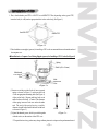
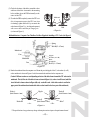
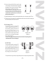
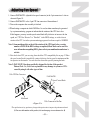
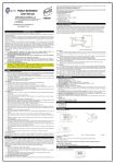
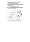
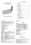
Zalman Tech Co., Ltd.
User’
s Manual
CNPS5100-Al
CNPS5100-AlCu
CNPS5100-Cu
http://www.zalman.co.kr
E-mail:[email protected]
CNPS5100-Al, CNPS5100-AlCu, CNPS5100-Cu
The CNPS5100-Al / CNPS5100-AlCu / CNPS5100-Cu coolers come with an adjustable
fan speed connector (FAN MATE 1) for allowing you to vary the CPU fan speed to
create an optimal cooling environment.
1. Features
1) Zalman’s CPU Coolers do not generate noise and vibration in silent mode.
2) The heat dissipating material of the Flower HeatSink (FHS) is pure copper or aluminum.
3) Innovative FHS(Flower HeatSink) design offers lower noise and thermal resistance.
4) With the included adjustable fan speed connector, the user can freely adjust the CPU fan's RPM.
5) Zalman’s CPU Coolers cool a CPU to a temperature sufficiently below the temperature required by
the CPU manufacturer without generating noise.
6) Zalman’s CPU Coolers offer very stable operation of a CPU in an OVERCLOCKED environment.
* If you try OVERCLOCKING, please make sure that the fan is in Normal Mode.
* Zalman Tech. Co., Ltd. is not responsible for any damage to systems or CPUs caused by CPU
OVERCLOCKING.
2. Components
1) One FHS assembly
3) One Fan (6025)
5) Four Tapered Springs
7) Thermal Grease
2) Bolts A / Bolts B / Bolts C - four each
4) Four Nipples (spacers)
6) One Sheet of Washers A (6 mm) and Washers B (8 mm)
8) One Adjustable Fan Speed Connector (FAN MATE 1)
3. Product Specifications
1) FHS
Model
Spec.
Dimensions (mm)
Weight (g)
Part NO.
F
H
S
CNPS5100-Al
238
ZM4360EE-Al
Dissipating Area (㎠)
CNPS5100-AlCu
CNPS5100-Cu
90 (L) × 66 (W) ×70(H)
290
454 (1)
ZM4360EE-AlCu
ZM4360EE-Cu
1500
Dissipating Material
Pure Aluminum
Pure Aluminum
+ Pure Cooper
Pure Cooper
Weight (g)
128
0.43
0.26
180
0.42
0.25
344
0.39
0.23
Thermal
Resistance
(℃/W)
Silent Mode
Normal Mode
Note 1) CNPS5100-Cu exceeds AMD’s heatsink mass specification of 300g, so special care should be
taken when moving the computer. Zalman Tech. Co., Ltd. is not responsible for any damage
to systems or CPUs caused by moving the computer after installing the CNPS5100-Cu.
2) Fan (GM1206PTVX-AF)
① Dimensions : 60(L) X 60(H) X 25(W) mm
③ RPM : 3000 RPM± 10% (Silent Mode)
5200 RPM ±10% (Normal Mode)
⑤ Bearing Type : Vapo Bearing
② Weight : 55g
④ Noise Level : 20dB ± 10% (Silent Mode)
36dB ± 10% (Normal Mode)
* The specifications of any product may change without prior notice to improve the performance thereof.
-1-
3) FAN MATE 1
① Dimensions : 200(L) X 23(W) X 21(H) mm
③ Output Voltage : 5V ~ 11V ± 2%
② Weight : 20 g
④ Allowable Wattage : 6W or lower
4. Compatibility of CPU : Socket 462 - AMD Duron, AMD Athlon, AMD Athlon XP
Socket 423 - INTEL Pentium 4
CPU Type
Silent Model
Silent Model
Duron
Athlon
Up to 1.6㎓
CNPS5100-Al
CNPS5100-AlCu Normal Model Up to 2.0㎓
CNPS5100-Cu
AMD
INTEL
Pentium 4
Model
Up to 1.7㎓
Support
all current
CPU Clock
speed
Athlon XP
Athlon XP
(T-Bird)
Up to 1.67㎓
Up to 2.0㎓
(2000+)
(2400+)
Over 2.13㎓(2600+)
1.4㎓
Up to 1.73㎓
Up to 2.13㎓
(2100+)
(2600+)
Over 2.13㎓(2600+)
Normal Model Over 2.0㎓
Note 2) This cooler cannot be mounted on a mainboard that does not have four holes around the socket.
Also, Socket 478 mainboards are not supported.
5. Please keep the following in mind for a noiseless computer
1) For a noiseless computer, a Noise Prevention (NP) Power Supply, a NP HDD, a NP CD-ROM and
a NP VGA CARD should be used together with this cooler.
2) Zalman affixes a Computer Noise Prevention System (CNPS) Mark to each of its parts and
components used for noiseless computers.
3) If a high-performance VGA card is required, it is preferable to use a NP VGA Card having a VGA FHS.
4) When buying a new VGA card, it is recommended to buy a fanless VGA card.
6. Caution
1) The CNPS5100-XX can be mounted only on a mainboard having four holes around the CPU socket.
2) For mainboards on which the CNPS5005-XX can be mounted, please refer to the list of approved
mainboards on Zalman’s web site (www.zalman.co.kr/english/product/ccc/usmainboard.htm).
3) If the RPM of the CPU fan cannot be measured, please update the BIOS to the latest version. For
more information on updating your BIOS, please refer to you the mainboard manufacturer’s web
site (There are some mainboards that cannot measure the RPM of fans in Silent Mode. However, this
will not affect the performance.
7. Patent Applications
◇ Korean Patent Application No. 01-11056
◇ Patent Applications Pending in over 20 nations around the world, including the U.S., EU, and Japan
* The specifications of any product may change without prior notice to improve the performance thereof.
-2-
Installation of FHS
1. First, check whether your CPU is a P4 CPU or an AMD CPU. Then, depending on the type of CPU,
insert the bolts (A or B) into the appropriate holes in the cooler body (See Figure 1).
Intel P4 CPU
AMD CPU
< Figure 1 >
2. Check whether or not nipples (spacers) for installing a CPU cooler are mounted between the mainboard and
the computer case.
◆ Installation in a Computer Case Having Nipples (spacers) for Installing a CPU Cooler (See Figure 2)
Spring
Bolt A(59-63mm)
Mainboard
Case Nipple
Case
Hole
Mainboard
< Figure 2 >
(1) Insert one of the provided bolts A into a tapered
spring as shown in Figure 2, and insert the bolt
A into an appropriate mounting hole (See Figure 1)
of the cooler body. Repeat until four bolts are in
stalled in the cooler body. (Caution! The diameter
of the spring increases from one end to the other
end. The end of the spring having a smaller
diameter should be directed to the head of the bolt
as shown in Figure 3.)
(2) Spread the thermal grease, which is provided together
with the cooler, on the surface of the CPU core.
Case
Good
Bad
< Figure 3 >
* The specifications of any product may change without prior notice to improve the performance thereof.
-3-
(3) Check the locations of the holes around the socket
and those of the bolts A mounted in the mounting
holes, and then place the FHS horizontally on the
center of the CPU.
Mainboard
(4) To make the FHS completely contact the CPU core
(this is important to protect the CPU core from
overheating), tighten each bolt A by one turn in the
order shown in Figure 2 (i.e., in a diagonal sequence)
with a screw driver until they no longer go in
(as shown in Figure 4).
Case
Good
Bad
< Figure 4 >
◆ Installation in a Computer Case That Does Not Have Nipples for Installing a CPU Cooler (See Figure 5)
Spring
Bolt B(42-47mm)
Mainboard
Case
Nipple
Washer (A or B)
Hole
Washer B
Mainboard
Case
Bolt C(6∼13mm)
< Figure 5 >
(1) Detach the mainboard from the computer case. Mount the provided nipples, bolts C, and washers (A or B)
on the mainboard as shown in Figures 5 and 6, then reattach the mainboard to the computer case.
(Caution! Different washers are used depending on the size of the holes formed around the CPU socket on the
mainboard. That is, if the size of the holes is 6 mm as shown in Figure 6(A), washer A and B is used, and if the
size of the holes is 4 mm as shown in Figure 6(B), only washer B is used. A bolt with a washer is used for the
upper part of the mainboard and another bolt with a washer isused for the lower part of the mainboard.)
Nipple
Washer A
(Inside Diameter : 6mm)
Mainboard
<A>
Washer B
(Inside Diameter : 4mm)
Washer B
(Inside Diameter : 4mm)
Bolt C
<B>
< Figure 6 >
* The specifications of any product may change without prior notice to improve the performance thereof.
-4-
(2) Insert one of the provided bolts B into a tapered spring
as shown in Figure 5, and insert the bolt B into an appropriate
mounting hole of the cooler body (See Figure 1). Repeat
until four bolts are installed in the cooler body.
(Caution! The diameter of the spring increases from
one end to the other end. The end of the spring having
Good
a smaller diameter should be directed to the head of
Bad
< Figure 7 >
the bolt as shown in Figure 7.)
(3) Spread the thermal grease, which is provided together with the cooler, on the surface of the CPU core.
(4) Check the locations of the nipple holes on the mainboard and the locations of the bolts B, and then place
the Cooler horizontally on the center of the CPU.
(5) For Pentium 4 CPUs :
To make the FHS completely contact the CPU
core (this is important to protect the CPU core
from overheating), tighten each bolt B by one
turn in the order shown in Figure 5 (i.e., in a
Good
Bad
Bad
diagonal sequence) with a screw driver. The
Pentium 4 CPU
bolts are mounted so that the height of the bolt
heads is the same as the height of the mounting
< Figure 8 >
holes (as shown in Figure 8).
(Caution! If the height of the bolt head is much lower than that of the mounting hole, the
mainboard and the CPU may be damaged.)
For AMD CPUs :
To make the FHS completely contact the CPU
core (this is important to protect the CPU core
from overheating), tighten each bolt B by one
turn in the order shown in Figure 5 (i.e., in a
diagonal sequence) with a screw driver until
they no longer go in (as shown in Figure 9).
Mainboard
Good
Bad
AMD CPU
< Figure 9 >
* The specifications of any product may change without prior notice to improve the performance thereof.
-5-
Adjusting Fan Speed
1. Connect FAN MATE 1 (adjustable fan speed connector) to the 3-pin connector of a fan as
shown in Figure 10.
2. Connect FAN MATE 1 to the 3-pin CPU fan connector of the mainboard.
3. Turn on the computer after assembly is finished.
4. When booting a computer in which FAN Mate 1 is used, an alarm sound may be generated
by a system monitoring program to indicate that the rotation of the CPU fan is slow.
If this happens, you may turn the speed control knob fully clockwise to increase the fan
speed, set“CPU Fan Detected”to“Disabled”in the BIOS settings, or set the slowest
rotation of the CPU fan in the system monitoring program to less than or equal to 1500RPM.
Note 1) Some mainboards do not boot if the rotation of the CPU fan is below a certain
number of RPM. If the BIOS settings are updated, Silent Mode can be used. For
’
more information on updating BIOS , please refer to your mainboard manufacturer’
s
web site.
5. First check what CPU you are using, then check the CPU compatibility list on page 2. When
the speed control knob is turned fully counter-clockwise, the fan speed is minimum and the
fan operates in silent mode. You can select the desired fan speed by turning the knob.
Note 2) FAN MATE 1 has been specifically designed for the fan of this product.
Zalman Tech. Co., Ltd. is not responsible for any damage to systems or CPUs
caused by using it with other types of fans.
3-Pin CPUFan Connector
FAN MATE 1
Speed Control Knob
Mainboard
3-Pin Connector of the Fan
< Figure 10 >
* The specifications of any product may change without prior notice to improve the performance thereof.
For more information on this product, visit our homepage at www.zalman.co.kr.
-6-