1
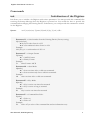
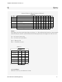
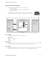
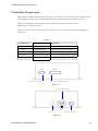
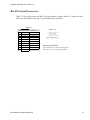
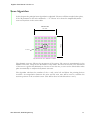
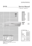
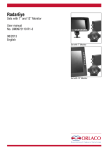
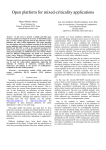
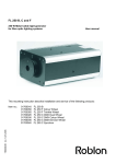
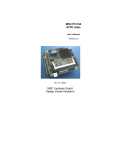
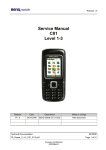
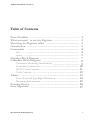
Digitizer User Manual Version 2.1
Table of Contents
Parts Checklist ……………………………………………… 2
What you need to use the Digitizer ……………………..… 2
Mounting the Digitizer tablet ….................................................. 2
Introduction …....................................................................... 3
Commands …....................................................................... 4
init ………........................................................................ 4
query …............................................................................. 5
Digitizer Block Diagram ….................................................... 7
Controller Block Diagram ….................................................. 8
Controller Mounting Information …................................... 9
Controller Connectors….................................................... 10
RS-232 Serial Connector …………........................................ 11
Tablet Connector ………….................................................... 12
Tablet ..….................................................................................. 13
Zero Point and Top Right Definition ……......................... 14
Mounting Information ……................................................ 15
Pointing Device .………......................................................... 16
Scan-Algorithm .………......................................................... 17
t&m elektronik, bielefeld-germany
1
Digitizer User Manual Version 2.1
Parts Checklist
The Digitizer System consists of:
●
●
●
●
●
●
Digitizer 3x1 Series digitizing tablet
Digitizer-Controller
Digitizer-Interface-Cable with 44-pin connector
Host interface cable with 9-pin connector
Cordless Pointing Device
Charger
Note: The Digitizer-Controller is a small enclosure and attached via the
Digitizer-Interface-Cable to the back of the tablet. The controller contains
the electronics that drive the Digitizer.
Picture 1-1
Connect the Digitizer-Interface-Cable here
What you need to use the Digitizer
● A Host with an RS232 Communication port
● Graphic application software that accepts digitizer input
● Optional a Vacuum-System at the back of the tablet
Mounting the Digitizer tablet
Picture 3-1
You can mount the tablet on a stable Al-Frame (s. Picture 3-1). Be
sure that the mounting-frame builds not an electrical closed frame,
because that decrease the magnetic field produced by the wires inside the tablet (s. Picture 3-2).
Picture 3-2
Isolation
The minimum distance between the table and an extra illumination device is 500mm (s. Picture 3-3). Use
an illumination device with low electrical and magnetic field emission, for example an LED-Illumination.
500 mm
Picture 3-3
Illumination
Device
Tablet
t&m elektronik, bielefeld-germany
2
Digitizer User Manual Version 2.1
Introduction
This document describes the command interface between a Host and the Digitizer. The Digitizer
uses two output-formats, ASCII and binary. All commands from the Host are in ASCII-Format
which can be send online or manually (use a terminal emulation program e.g. Tera Term). Any
command can be given at any point of time even during an active data connection. Each command
line sent to the Digitizer consists of a body (if applicable) and a terminator.
The command-line uses ASCII-Characters in the range from 32 to 127. Control characters other
than <CR> and <STX> (carriage return → ASCII 0x0D - Start of Text → ASCII 0x02) in a
command line are disregarded. Characters are case sensitive.
Parameters must be with minimum of one Blank-Character. The first value after each parameter
must be followed immediately, subsequent values are comma separated.
Terminator is <CR>.
There are two types of responses - information text and result codes - which are sent back to the
Host. Information text may consist of a single line or multiple lines and are always ASCII-Characters.
Result codes may be transmitted in ASCII-Format or Binary-Format depending of Parameter “F“
in the initialization command.
Connection between the Host and the Digitizer uses a RS232 interface with the following settings:
38400 bps, 8 data bits, no parity, 1 stop bit (8/N/1), no handshake.
Power on the Digitizer and remain until the startup message is received.
Startup Message: >Digitizer v.x.x
Subsequent to received the Startup Message the Digitizer must be initialized. If one provides a new
command the prior command will be suspended except for the init-command.
t&m elektronik, bielefeld-germany
3
Digitizer User Manual Version 2.1
Commands
init
Initialisation of the Digitizer
Init allows you to initialize the Digitizer with various parameters. You must provide this command after
receiving the Startup Message when the Digitizer is powered on. You would also have to provide this
command when changing the Pointing-Device. Furthermore, you could provide this command to reinitialize the Digitizer.
Syntax:
init N[n1,n2,n3,n4] F[format] M[mode] K[key] E[echo]<CR>
Parameter N → Serial number from the Pointing-Device (Factory setting)
N[n1,n2,n3,n4]
● n1,n2,n3: values from 0 to 255
● n4 even-numbered values from 0 to 254
Example:
N12,255,0,4 → serial number 12 255 0 4
Parameter F → Output-Format
F[format]
● 1 = ASCII-Format
● 2 = Binary Format
Example:
F1
Data-Format: ASCII
Parameter M → Scan-Mode
M[mode]
● 1 = Scan one time after a valid scan-command
● 2 = Scan continuously after a valid init-command
Example:
M1
Scan one time after a valid scan-command
Parameter K → Key-Mode
K[mode]
● 1 = Key is active one time after actuated
● 2 = Key is active as long as actuated
Example:
K1
Key is active one time after actuated
Parameter E → Command-line Echo
E[echo]
● 1 = Echo on
● 2 = Echo off
Example:
E2
Echo off (no echo of the command-line and no information text)
t&m elektronik, bielefeld-germany
4
Digitizer User Manual Version 2.1
Commands
Q
Query
Query returns the x/y-Position, the Key-Code and Status-Information in ASCII or Binary-Format
depending of the “F“ Parameter in the init-command. For this command no body is required.
The Digitizer has two different scan-modes, depending on the M-Parameter given by the
init-command. In asyncron scan-mode (M-Parameter=1), the query-command initiate one scan
and the Digitizer responds with a return-information. In syncron scan-mode (M-Parameter=2), the
query-command returns the latest scan-information from the Digitizer.
Syntax: Q<CR>
Returnd Values in ASCII_FORMAT as followed
Table 5-1
1. Character
2. Character
3. Character
4. Character
5. Character
6. Character
7. Character
8. Character
9. Character
10.Character
11.Character
12.Character
13.Character
Start of Text
Status
Key-Code
x-Coordinate high
x-Coordinate
x-Coordinate
x-Coordinate
x-Coordinate low
y-Coordinate high
y-Coordinate
y-Coordinate
y-Coordinate
STX
0…3
0…6
0…9
.
.
.
.
.
.
.
.
0x02
0x30 … 0x33
0x30 … 0x36
0x30 … 0x39
.
.
.
.
.
.
.
.
y-Coordinate low
.
.
Status:
0 = Key-Code and x/y-coordinates are valid values
1 = Key-Code and x/y-coordinates are valid values and Low-Batterie is active
2 = Cursor is out of proximity
3 = Cursor is out of proximity and Low-Batterie is active
Key-Code:
0 = No Key is activated
1 = Key 1 is activated
2 = Key 2 is activated
3 = Key 3 is activated
4 = Key 4 is activated
5 = Key 5 is activated
6 = Key 6 is activated
x/y-coordinate:
The unit of the x/y-coordinate is 0.1 mm
t&m elektronik, bielefeld-germany
5
Digitizer User Manual Version 2.1
Q
Query
Returnd Values in Binary-Format as followed
Byte
1
2
3
4
5
6
7
8
Bit
Status
Key-Code
x-Coordinate low-order Byte
x-Coordinate
x-Coordinate high order Byte
y-Coordinate low-order Byte
y-Coordinate
y-Coordinate high order Byte
Table 5-2
7
1
0
0
0
0
0
0
0
6
5
1
0
0
0
0
0
0
0
4
3
2
0
0
0
0
0
0
0
k2
x5 x4 x3 x2
x11 x10 x9 x8
0
0 x15 x14
y5 y4 y3 y2
y11 y10 y9 y8
0
0 y15 y14
1
0
Bat Pr
k1 k0
x1 x0
x7 x6
x13 x12
y1 y0
y7 y6
y13 y12
Status
The highest two bits in the Status-Byte are always “1“. This indicates the launch of a data transfer
and can easily be used for synchronization In all subsequent bytes the highest two bits are zero.
Pr = 0 Cursor in active area
Pr = 1 Cursor out of proximity
Bat = 0 Battery OK
Bat = 1 Low Batt is active
Table 5-3
Key-Code
Key-Number
k2
k1
k0
No Key
0
0
0
1
0
0
1
2
0
1
0
3
0
1
1
4
1
0
0
5
1
0
1
6
1
1
0
x/y-coordinate
The unit of the x/y-coordinate is 0.1 mm
t&m elektronik, bielefeld-germany
6
Digitizer User Manual Version 2.1
Digitizer Block Diagram
The principal Digitizer configuration are shown in the simplified block diagram in Figure 6-1.
There are three parts which are used to implement one Digitizer:
● The Controller
● The Tablet
● A Cordless Pointing Device
All three parts are described in more detail later in this chapter. The Digitizer uses only one external
Power Supply (24 VDC). Communication between a Host-Computer and the Digitizer uses a
standard RS232 connection with a simple protocol which are described in chapter Query on page
4 and 5.
Digitizer
Host
Tablet
Cordless
Pointing Device
Interface Cable
44pol DSUB
24V DC
RS232
Controller
Figure 6-1
t&m elektronik, bielefeld-germany
7
Digitizer User Manual Version 2.1
Controller Block Diagram
The Controller is divided in to three parts (see Figure 7-1):
● The Power Supply
● The FPGA-Board with Logic and a 32Bit Softprocessor
● The Driver-Board
Picture 7-1
All three parts are covered in a small case (Picture 7-1 on the right side)
The mechanical dimensions of the case are described later in this chapter.
Driver-Board
Tablet
Interface
44pol DSUB
FPGA-Board
Scan-Logic
FLASH
Logic
Power-Supply
Input:
24V
Output1: 12V
Output2: 3.3V
SDRAM
Host
Interface
9pol DSub
RS232 TTL
32Bit Microcontroller
NIOSII
Figure 7-1
Power Supply
The power supply is integrated on the Driver-Board.
Specification
Input:
24VDC 1A
Output 1:
12V
Output 2:
3.3V
FPGA-Board
The main part of this board is a FPGA (Altera Cyclone III). The FPGA contains a 32Bit
Softprocessor NIOS II and the necessary logic to scan the wires on the tablet.
Driver Board
The Driver-Board connects the controller and the tablet over a 44-pin Connector. For optimal
noise immunity all logic signals are converted to a 3.3V-RS422 like differential signal.
t&m elektronik, bielefeld-germany
8
Digitizer User Manual Version 2.1
Controller Mounting Information
The main measures of the controller case are shown in Figure 7-2.
165 mm
FRONT VIEW
124 mm
TOP VIEW
65 mm
Tablet
69.5 mm
Host
178 mm
190 mm
Figure 7-2
t&m elektronik, bielefeld-germany
9
Digitizer User Manual Version 2.1
Controller Connectors
This chapter contains information about the I/O connectors on the front panel and back panel
of the Digitizers Controller, including pinouts and signal descriptions for each connector.
Table 7-1 summarizes the functions of the connections and the controls on the
Digitizers front and back panel
Figure 7-3 shows the front panel layout and Figure 7-4 shows the back panel for a Digitizers
Controller.
Table 7-1
I/O Interface
External Connector
Description
-1- Serial
9-pin DSUB male
RS232 Serial Port
-2- Tablet
50-pin DSUB male
External Twisted-Pair I/O-Signals
-3- Fuse
-4- Power
1A
3-pin Power connector
-6- Switch
18 - 36 V DC reverse polarity protected
Power ON/OFF Switch
HOST
-1- RS-232 Serial Connector
TABLET
-2- 44pol DSUB Tablet connector
Figure 7-3
-4- Power Supply Connector
24 V
-3- FUSE 1 A
-5- ON/OFF Switch
Figure 7-4
t&m elektronik, bielefeld-germany
10
Digitizer User Manual Version 2.1
RS-232 Serial Connector
Table 7-2 lists and describes the RS-232 serial connector signals. Picture 7-1 shows the location of the Pin-Number from the 9 pin DSUB female connector.
Table 7-2
RS-232 Serial Connector
Pin Signal Name Signal Description
1
n.u.
2
TxD
Transmit Data
3
RxD
Receive Data
4
n.u.
5
GND
Ground
6
n.u.
7
n.u.
8
n.u.
9
n.u.
t&m elektronik, bielefeld-germany
Picture 7-1
Internal connection
Pin 1,4 and 6 are connected together
Pin 6 and 7 are connected together
11
Digitizer User Manual Version 2.1
Tablet Connector
Table 7-3 lists and describes the connector signals between the Controller and the Tablet.
Picture 7-2 shows the location of the Pin-Number from the 44 pin DSUB female connector.
Table 7-3
Pin Signal Name
Signal Description
Pin Signal Name
16
+3.3V
y-Shift-Clock +
17
xSTCP+.
ySHCP-
y-Shift-Clock -
18
xSTCP-.
4
y/MR+
y-Reset-Shift-Register+
19
5
y/MR-
y-Reset-Shift-Register-
6
GND
Signal Ground
1
+3.3V
2
ySHCP+
3
Signal Description
Pin Signal Name
31
+3.3V
x-Store-Data-Clock+
32
P2.4-
x-Store-Data-Clock-
33
P2.4+
x485+
x-Shift-Data+
34
P4.3+
20
x485-
x-Shift-Data-
35
P4.3-
Signal Ground
36
GND
21
GND
37
P2.2-
38
P2.2+
39
+12V
7
ySTCP+.
y-Store-Data-Clock+
22
P4.6+
8
ySTCP-.
y-Store-Data-Clock-
23
P4.6-
9
GND
Signal Ground
24
GND
10
y485+
y-Shift-Data+
25
P4.5+
40
P2.3+
11
y485-
y-Shift-Data-
26
P4.5-
41
P2.3-
12
+3.3V
27
P2.0-
42
P2.0+
13
xSHCP+
x-Shift-Clock +
28
P4.4-
43
P2.1+
14
xSHCP-
x-Shift-Clock -
29
P4.4+
44
P2.1-
15
x/MR+
x-Reset-Shift-Register+
30
x/MR-
Signal Ground
Signal Description
+12V-Ground
x-Reset-Shift-Register-
Picture 7-2
31
44
16
30
1
15
t&m elektronik, bielefeld-germany
12
Digitizer User Manual Version 2.1
Tablet
The tablet shown in Figure 8-1 consists of a Tablet-Adapter with an integrated RF-Module for
communication with the Pointing Device and the necessary x- and y-wire-driver. The distance
between each wire in x- and y-direction is 20mm. The maximum active scan-area in x- and
y-direction can calculated from the following formula:
Scan-area in x- or y-direction = (((n x 16) - 1) x 20mm) - 80mm
Where “n” is the number of boards of the corresponding x- or y-direction
Example:
10 boards in x-direction - all wires connected
3 boards in y-direction - all wires connected
Calculation in x- direction: x-scan = (((10 x 16) - 1) x 20mm) - 80mm = 3100mm
Calculation in x- direction: y-scan = (((3 x 16) - 1) x 20mm) - 80mm = 860mm
50pol DSub
Tablet
Radio
Module
x1-Board
16 wires
x10-Board
16 wires
y1-Board
16 wires
y2-Board
16 wires
y3-Board
16 wires
16 x-wires
16 x-wires
Tablet-Adapter
16 y-wires
16 y-wires
16 y-wires
Figure 8-1
Picture 8-1
Picture 8-1 shows one x-board that can drive
16 wires. Connection to the next board is
made via a 20pol flat cable.
t&m elektronik, bielefeld-germany
13
Digitizer User Manual Version 2.1
Zero Point and Top Right Definition
The zero point definition is shown in Figure 8-2 Detail “A”. It is 40mm away from the first wire
in either x- and y-direction. The top right definition in Figure 8-2 Detail “B”. It is 40mm away
from the last wire in either x- and y-direction
Radio
Module
x1-Board
16 wires
x10-Board
16 wires
16 x-wires
16 y-wires
16 y-wires
Zero Point Position
Detail “A”
Top right
n
6
n-3
n-4
n-5
Figure 8-2
Detail “B”
6
40mm
Zero Point
3
2
1
40mm
y-direction
n
16 y-wires
x-direction
1 2 3
Top Right Position
Detail “B”
x-direction
n-4
n-5 n-3
y-direction
y1-Board
16 wires
y2-Board
16 wires
y3-Board
16 wires
16 x-wires
Tablet-Adapter
40mm
50pol DSub
Tablet
40mm
Detail “A”
t&m elektronik, bielefeld-germany
14
Digitizer User Manual Version 2.1
Mounting Information
The Tablet consists of three parts. Two cover plats and one base plate. All plates contains hole for
vacuum (s. Detail “D”). The vacuum case has to be mounted by the user. All electronic components for wire activation are mounted in the base plate (s. Figure 8-1 on page 13). Figure 8-5 Detail
“C” shows the position of the 44 pin DSUB tablet connector.
8 mm
Cover plate
Figure 8-3
19 mm
Base plate
wire x1
155 mm
Detail “C”
Figure 8-4
wire xn
n = Number of max. wires
(ny-1)x20 mm
wire yn
45 mm
Vacuum holes
110 mm
105 mm
Figure 8-5
105 mm
Detail “C”
150 mm
(nx-1)x20 mm
wire y1
44 Pin DSUB
Tablet Connector
t&m elektronik, bielefeld-germany
15
Digitizer User Manual Version 2.1
Pointing Device
A simplified Logic Diagram of the Pointing Device is shown in Figure 9-1 (some features not
shown). The Circuit-Board contains the necessary Filter and Amplifier to detect the magnetic field
generated from the wires inside the tablet. The MPS430 Microcontroller digitizes the received
analog magnetic field and send this information to the tablet over air. Furthermore the Microcontroller scans the keys and detect a low voltage of the battery.
The Pointing Device contains a Lithium Polymere Battery to operate about 10 hours without
charging.
The main measures of the Pointing Device is shown in Picture 9-1.
Pointing Device - Circuit-Board
RF-Controller
Coil with Crosshair-Cursor
MSP430
Microcontroller
Filter
External
Charger
Batterie
On/Off-Switch
Figure 9-1
25 mm
Picture 9-1
62 mm
5
4
6
3
1
2
Out of Scan-Area LED
External
Charger
On/Off Switch
On/off LED
170 mm
t&m elektronik, bielefeld-germany
16
Digitizer User Manual Version 2.1
Scan-Algorithm
In this chapter the principal scan-algorithm is explained. The most efficient method takes place,
if the M-parameter in the init command is = “2”. Picture 10-1 shows the simplified dynamic
scan area anywhere in the entire tablet.
140 mm
Picture 10-1
140 mm
Cursor
Dynamic Scan-Area 140mm x 140mm
The dynamic scan-area follows the movement of the cursor. The cursor is approximately in the
middle of this area, except on the boundaries of the tablet. This area can be lost, if the movement
of the cursor is grater then 900mm/sec. In case of lost this area, a scan over the whole tablet takes
place automatically to readjust the dynamic scan-area.
The algorithm calculates the number of the x- and y-wire left and below the pointing devices
crosshair. An interpolation between this wire and the next wire will be used to calculate the
accurate position of the crosshair cursor. This will be done in both directions x and y.
t&m elektronik, bielefeld-germany
17