1
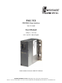
PAS 153
PROFIBUS Slave Interface
700-153-1AA03
User Manual
Edition 2 / 19.11.09
HW 1 and FW 1.00 and higher
Order number of manual: 900-153-1AA03/en
Systeme Helmholz GmbH z Hannberger Weg 2 z D-91091 Großenseebach
Phone: +49 9135 7380-0 z Fax: +49 9135 7380-110 z E-Mail: [email protected] z Internet: www.helmholz.de
All rights are reserved, including those of translation, reprinting,
and reproduction of this manual, or parts thereof. No part of this
manual may be reproduced, processed, copied, or transmitted in
any way whatsoever (photocopy, microfilm, or other method)
without the express written permission of Systeme Helmholz
GmbH, not even for use as training material, or using electronic
systems. All rights reserved in the case of a patent grant or
registration of a utility model or design.
Copyright © 2009 by
Systeme Helmholz GmbH
Hannberger Weg 2, 91091 Grossenseebach, Germany
Note:
We have checked the content of this manual for conformity with
the hardware and software described. Nevertheless, because
deviations cannot be ruled out, we cannot accept any liability for
complete conformity. The information in this manual is regularly
updated. When using purchased products, please heed the latest
version of the manual, which can be viewed in the Internet at
www.helmholz.de, from where it can also be downloaded.
Our customers are important to us. We are always glad to receive
suggestions for improvement and ideas.
.
Step and SIMATIC are registered trademarks of SIEMENS
Revision history of this document:
Edition
Date
Revision
1
17.04.2009
1st version
2
19.11.2009
Restricted use of modules with hardware release smaller 30
Contents
PAS 153
1
Safety Information ............................................................ 7
1.1
General .............................................................................. 7
1.2
Restriction of access .......................................................... 8
1.3
Information for the user ................................................... 8
1.4
Use as intended ................................................................. 8
1.5
Avoiding use not as intended! .......................................... 8
1.6
Installation and mounting instructions ........................... 8
2
Installation and Mounting ................................................ 9
2.1
Mounting orientation ....................................................... 9
2.2
Minimum clearance ........................................................ 10
2.3
Mounting of the module on the DIN rail ....................... 11
3
System Overview............................................................. 12
3.1
Application and function description............................. 12
3.2
Connections .................................................................... 12
3.3
LED displays .................................................................... 13
3.4
Accessories....................................................................... 13
4
Configuration.................................................................. 14
4.1
Hardware configurer ....................................................... 14
4.2
4.2.1
4.2.2
4.2.3
Device-specific parameters .............................................. 15
Diagnostic alarm ............................................................. 15
Process alarm................................................................... 15
Start-up if the actual configuration is not the planned
configuration .................................................................. 15
4.3
Error diagnosis using the indicator LEDs........................ 16
4.4
4.4.1
4.4.2
4.4.3
4.4.4
4.4.5
4.4.6
Error diagnosis using Profibus diagnostics...................... 18
Structure of the Profibus diagnosis ................................. 18
Standard diagnostic information (station status) ........... 19
Code-related diagnostics ................................................. 20
Module status .................................................................. 21
Channel-related diagnosis .............................................. 22
Alarms ............................................................................. 23
4.5
Address setting ................................................................ 24
5
6
4.6
Programming .................................................................. 24
4.7
4.7.1
4.7.2
Modules supported.......................................................... 25
Digital.............................................................................. 25
Analog ............................................................................. 26
4.8
Modules not supported ................................................... 26
4.9
Restricted use................................................................... 26
5
Further Information ........................................................ 27
5.1
Technical data ................................................................. 27
5.2
Pin assignment ................................................................ 28
5.3
Further documentation................................................... 28
PAS 153
1
Safety Information
For your own safety and for the safety of others, always heed the
safety information given here. The safety information indicates
possible hazards and provides information about how you can
avoid hazardous situations.
The following symbols are used in this manual.
!
Caution, indicates hazards and sources of error
i
Gives information
Hazard, general or specific
Danger of electric shock
1.1
General
The PAS 153 module is only used as part of a complete system.
!
The operator of a machine system is responsible for observing
all safety and accident prevention regulations applicable to the
application in question.
During configuration, safety and accident prevention rules
specific to the application must be observed.
Emergency OFF facilities according to EN 60204 / IEC 204
must remain active in all modes of the machine system. The system
must not enter an undefined restart.
Faults occurring in the machine system that can cause damage
to property or injury to persons must be prevented by additional
external equipment. Such equipment must also ensure entry into a safe
state in the event of a fault. Such equipment includes electromechanical
safety buttons, mechanical interlocks, etc. (see EN 954-1, risk
assessment).
Never execute or initiate safety-related functions using an
operator terminal.
PAS 153
7
1.2
Only authorized persons
must have access to the
modules!
Restriction of access
The module is an open item of equipment and must only be
installed in electrical equipment rooms, cabinets or housings.
Access to the electrical equipment rooms, barriers, or housings
must only be possible using a tool or key and only permitted to
personnel having received instruction or authorization.
1.3
Information for the user
This manual is addressed to anyone wishing to configure, use, or
install the PAS 153 module.
During configuration,
safety and accident
prevention rules specific
to the application must
be observed.
It is intended for use as a programming manual and reference
work by the configuring engineer. It provides the installing
technician with all the necessary data.
The PAS 153 module is for use in a Profibus network only. For
that reason, the configuring engineer, user, and installing
technician must observe the standards, safety and accident
prevention rules applicable in the particular application. The
operator of the automation system is responsible for observing
these rules.
1.4
Use as intended
The PAS 153 module must only be used as a Profibus interface as
described in the manual.
1.5
Make sure in the
software that
uncontrolled restarts
cannot occur.
Avoiding use not as intended!
Safety-related functions must not be controlled using the PAS 153
module alone.
1.6
Installation and mounting instructions
Installation and mounting must be effected in compliance with
VDE 0100 IEC 364.
Before you start
installation work, all
systems must be
disconnected from their
power source.
8
PAS 153
2
Before you start
installation work, all
system components must
be disconnected from
their power source.
Installation and Mounting
Installation and mounting must be effected in compliance with
VDE 0100 / IEC 364. Because it is an “OPEN type” module, you
must install it in a cabinet.
The maximum ambient temperature of +40°C for vertical
installation and +60 ºC for horizontal installation must be
complied with to ensure reliable operation.
2.1
Mounting orientation
The PAS 153 module can be installed with any orientation.
i
The module can be
mounted either vertically
or horizontally.
PAS 153
Permissible ambient temperature:
•
for vertical mounting: from 0°C to +40°C
•
for horizontal mounting: from 0°C to +60℃
9
2.2
Minimum clearance
Minimum clearances must be observed because
Non-observance of the
minimum distances can
destroy the module at
high ambient
temperatures!
•
they ensure sufficient cooling of the module.
•
it is then possible to insert and remove the PAS 153 module
without having to remove other system components.
•
there is enough space to connect existing connectors and
contacts using standard commercial type accessories.
•
there is room for any necessary cable routing.
•
it increases the mounting height of the module rack to 185
mm, although the minimum spacing of 40 mm must still
be observed
For the PAS 153 module, a minimum clearance of 40 mm must be
left above and below and 20 mm at the sides.
The following diagram shows the minimum spacing between the
module racks and between these and any adjacent cabinet walls,
equipment, cable ducts, etc. for S7-300s mounted in several
module racks.
10
PAS 153
2.3
Mounting of the module on the DIN rail
A wall/DIN rail bracket is available as an accessory for mounting
on flat surfaces or on DIN rails.
When connecting the bus connector, always start with the
PAS 153 module.
Do not plug a bus connector into the last module of the tier:
Hook on the module (1), slide it up to the left module (2), and
click it downward (3).
Screw the modules on with a torque of 0.8 to 1.1 Nm.
The available accessories are listed in Section 3.4 with the
corresponding order numbers.
PAS 153
11
3
3.1
System Overview
Application and function description
The PAS 153 Profibus Slave Interface is for linking digital and
analog input and output modules to the Profibus DP. The module
can be mounted on a sectional rail.
Up to 16 modules can be connected to the PAS 153, including 8
parameterizable modules.
The PAS 153 is integrated into the hardware configurer of the
programming system by a GSD file. The PAS 153 interface
performs all communication between the modular I/O device and
the higher-level master unit on the Profibus-DP.
i
Active backplane bus
modules are currently not
supported.
The inputs and outputs are assigned to the master during
configuration. The PAS 153 module supports all digital and
analog input/output modules from Systeme Helmholz and also
numerous modules of the same type from other manufacturers.
For more details, see Section 4.7, “Modules supported” on page 25
ff.).
The PAS 153 module works according to DP/V0 and supports
baudrates of 9.6 Kbaud to 12 Mbaud. The baudrate is detected
automatically.
3.2
Connections
Behind the protective flap on the front of the module, you will
find the connectors for the power supply and a SUB-D female
connector for the Profibus. Behind the transparent flap, you will
find an 8-pole DIL switch for address setting.
12
PAS 153
3.3
LED displays
The PAS 153 module has three LEDs for
indicating its operating status. These are labeled
- SF (lights up red),
- BF (lights up red) and
- ON (lights up green).
The meaning of the LEDs for diagnostics is
described in Section 4.3 on page 16.
3.4
PAS 153
Accessories
Manual, German/English
900-153-1AA03
Profibus connector 90°
700-972-0BA12
Profibus connector 90° with PG conn. socket
700-972-0BB12
Profibus connector 35°
700-972-0BA41
Profibus connector 35° with PG conn. socket
700-972-0BB41
Profibus connector with axial cable outlet
700-972-0CA12
Insulation stripping tool for Profibus
700-972-6AA00
Compact repeater
700-972-0RB12
Repeater for MPI and Profibus
700-972-0AA02
13
4
4.1
Configuration
Hardware configurer
The PAS 153 module is integrated into the programming software
of the PLC via a GSD file. This integration is explained below
using the Siemens STEP7 programming software.
To be able to use the PAS 153 in the hardware configuration, the
GSD file must be installed once. First copy the GSD file (named:
“HELM0BED.GSE”) supplied to any location on your hard disk.
Then choose the “Install GSD files” function from the “Options”
menu in the hardware configuration of STEP7, go to the directory
to which you copied the file, and then select the file there.
The information about the PAS 153 module is now added to the
selection catalog of the hardware configurer.
You will find the PAS 153 module in the catalog under
“PROFIBUS-DP / Additional FIELD DEVICES / I/O / HELMHOLZ /
PAS153”
Configuration then continues in the same way as for Profibus
stations.
14
PAS 153
4.2
Device-specific parameters
4.2.1
Diagnostic alarm
Enable diagnostic alarm
In the case of a module/channel error of a digital or analog
module, a Profibus diagnosis, consisting of a standard diagnosis,
code-related diagnosis, modules status, channel-related diagnosis,
and alarm, incl. diagnostic record 1 is output.
Diagnostics alarm disabled
In the case of a diagnostic alarm of a digital or analog module, no
Profibus diagnosis is output.
4.2.2
Process alarm
Enable process alarm
In the case of a process alarm of a digital or analog module, a
Profibus diagnosis consisting of a standard diagnosis, code-related
diagnosis, module status, and alarm is output.
Process alarm disabled
In the case of a process alarm of a digital or analog module, no
Profibus diagnosis is output.
4.2.3
Start-up if the actual configuration is not the planned
configuration
1) Start-up activated
If a difference is found between the planned and actual
configuration, the PAS 153 module starts data exchange with
the DP master. Exchange of useful data with modules without
a planned/actual deviation is possible. The SF LED lights up
red.
2) Start-up deactivated
If a difference is found between the planned and actual
configuration, the PAS 153 module does not start data
exchange with the DP master. A configuration error is
detected and the SF LED lights up and the BF LED flashes.
PAS 153
15
4.3
Error diagnosis using the indicator LEDs
The PAS 153 module has three LEDs on the front (for LEDs, see
also Section 3.3). An initial diagnosis is possible using the
indications shown by these LEDs. The LED signals mean:
SF
BF
ON
Meaning
Remedy
OFF
OFF
OFF
No voltage applied
ot module or module
defective
Switch on
power supply
module or
exchange the
PAS 153
module.
OFF
OFF
ON
Error-free operation
(Data_Exchange)
The DP master is in
Operate / Run
-
OFF
OFF
FLASHING
Error-free operation
(Data_Exchange)
The DP master is in
Clear / Stop
-
ON
OFF
ON /
FLASHING
Impermissible
Profibus address
Set a valid
Profibus address
on the PAS 153
(1 - 125)
Start-up activated if
actual config. not
equal to planned
config.? If so, then
deviation between
planned and actual
configuration.
Check the
configuration in
the hardware
configurer.
Is the SF LED of a
digital or analog
module also lit? If
so, then error or
diagnosis in the
corresponding
digital or analog
module.
Check the
digital or analog
module with
the diagnosis.
Difference between
the actual and
planned
configuration.
Check the
configuration in
the hardware
configurer.
ON
16
FLASHING
ON
PAS 153
PAS 153
SF
BF
ON
Meaning
Remedy
OFF
FLASHING
ON
PAS 153 is
incorrectly
parameterized –
there is not data
exchange between
the DP master and
the PAS 153.
Causes:
Configured and set
Profibus addresses do
not match
Faults on the bus
Check the
Profibus address
on the PAS 153
and in the
hardware
configurator
Note: The
Profibus address
of the PAS 153
will only be
applied after the
next power
reset.
Check cable
lengths with
respect to
baudrate.
Check setting of
the terminating
resistors
OFF
ON
ON
No connection to
the DP master
(baudrate search)
Causes: Bus
communication via
PROFIBUS DP to the
PAS 153 has been
interrupted.
Check the bus
structure
(connectors and
cabling)
17
4.4
Error diagnosis using Profibus diagnostics
4.4.1
Structure of the Profibus diagnosis
If the diagnostic alarms of the PAS 153 module and the digital
and analog modules are enabled and a digital or analog module
detects an error, the PAS 153 module outputs a Profibus diagnosis.
The detected errors are entered there as a channel-related
diagnostic messages. At the same time, the SF LED of the PAS 153
module lights up.
i
The Profibus diagnosis
can contain multiple
module error messages
at the same time!
The Profibus diagnosis has the following structure:
Byte No.
Meaning
0
1
2
3
Station status 1 to 3
(see Section 4.4.2)
Master PROFIBUS address
High byte of the manufacturer ID code
(in this case: 0x0B for Helmholz)
Low byte of the manufacturer ID code
(in this case: 0xED for Helmholz)
4
5
6
7
8
9
:
16
17
18
19
:
Code-related diagnosis
(see Section 4.4.3)
Module status
(see Section 4.4.2)
:
:
x up to
last byte
(max. 244)
(max.
29 bytes)
Channel-related diagnosis
(3 bytes per error message;
see Section 4.4.5)
:
(any other necessary channel-related
diagnoses, each with 3 bytes)
:
Alarms (only 1 alarm possible per slave
diagnostic telegram;
see Section 4.4.6)
The maximum length of the diagnostic telegram of the PAS 153
module is 244 bytes.
18
PAS 153
4.4.2
Standard diagnostic information (station status)
The first 3 bytes of the diagnostic telegram contain the station
status information.
Byte 0
Bit 7 6 5 4 3 2 1
0 Meaning of “1”
DP slave not responding
DP slave not ready
Configuration error
External diagnosis available
Requested function is not supported by the slave
Invalid response of the slave
Slave type does not match the configuration
Slave has been parameterized by another DP master
Byte 1
Bit 7 6 5 4 3 2 1 0
Meaning of “1”
DP slave must be re-parameterized and reconfigured
Slave cannot provided valid useful data (e.g.
during start-up)
Always “1”
Response monitoring activated
Module has received a freeze command
Module has received a sync command
DP slave not contained in the master parameter set
DP slave has been removed from the master parameter set
Byte 2
Bit 7 6 5 4 3 2 1 0
Meaning of “1”
Reserved (always “1”)
There are more channel-related messages than can be stated in
the diagnostic telegram.
PAS 153
19
4.4.3
Code-related diagnostics
Bytes 6 to 8 contain the code-related diagnosis.
Byte 6
7
6
0
1
5
4
3
2
1
0
0
0
0
1
Length of the code-related diagnostic
information (in this case: 3 bytes)
Code-related diagnosis available
Byte 7
0
1
7 6 5 4 3 2 1 0 Entry for module in slot
1
2
3
4
5
6
7
8
Byte 8
7 6 5 4 3 2 1 0 Entry for module in slot
9
10
11
12
13
14
15
16
The bit assigned to slot in question is set to “1” if
- there is no module in it;
20
-
there is a non-configured module in it;
-
the module in question has reported a
diagnostic alarm;
PAS 153
4.4.4
Module status
The module status signals the status of the configured modules
and provides more detail with respect to the configuration than
the code-related diagnosis.
The module status begins after the code-related diagnosis and fills
8 bytes.
The module status is structured as follows:
Byte 9
7
6
5
4
0
0
0
7
6
5
4
1
0
0
0
3
2
1
0
0
1
0
0
0
Length of the module status incl. byte 9
(in this case: 8 bytes)
Code for device-related diagnosis
Byte 10
3
2
0
0
2H = module status
1
0
1
0
1
0
Code for status message
Byte 11
Byte 12
0H
0H
Byte 13
7
Always “0”
Always “0”
6
5
4
3
2
Status mod. 1
Status module 2
Status module 3
Status module 4
Byte 14
7
6
5
4
3
2
1
0
Status mod. 5
Status module 6
Status module 7
Status module 8
Byte 15
7
6
5
4
3
2
1
0
Status mod. 9
Status module 10
Status module 11
Status module 12
Byte 16
7
6
5
4
3
2
1
0
Status mod 13
Status module 14
Status module 15
Status module 16
The displayed status values mean:
Value Meaning
00B
01B
10B
11B
B
B
B
B
PAS 153
Module OK, valid data
Module defective, invalid data
Incorrect module, invalid data
No module, invalid data
21
4.4.5
Channel-related diagnosis
The channel-related diagnosis provides information about the
channel errors of modules and provides details of the code-related
diagnosis. It starts after the module status. The channel-related
diagnosis does not influence the module status.
Important: The diagnostic alarm must be enabled for every
module!
The maximum number of channel-related diagnoses is limited by
the maximum total length of the Profibus diagnostic telegram of
244 bytes. The length of the Profibus diagnostic telegram depends
on the number of currently available channel-related diagnoses.
Note:
Errors concerning all channels of a module (for example, if the
power supply of the module is missing) are only mapped on
channel 0 in the channel-related diagnosis. This keeps the
number of channel-related diagnoses low and avoids a flood of
diagnoses.
Byte 17
7
6
5
1
0
x
x
X
x
x
x
Code number of the module supplying the
channel-related diagnosis
(000000B to 001111B)
Example:
Slot 1 has code number 000000B
Slot 5 has code number 000100B
4
3
B
2
1
0
B
B
B
Channel-related diagnosis available
Byte 18
7
6
5
x
x
x
x
X
x
x
x
Number of the channel or the channel group
supplying the diagnostic information
(000000B to 111111B)
4
3
B
2
1
0
B
01B: Input
10B: Output
11B: Input/output
B
B
B
Byte 19
7
6
5
4
x
x
x
x
X
x
x
x
Error type according to Profibus
standard
3
2
1
0
Channel resolution:
001B: 1 bit
010B: 2 bits
011B: 4 bits
100B: 1 bytes
101B: 1 word
110B: 2 words
B
B
B
B
B
B
22
PAS 153
4.4.6
Alarms
The alarm part of the diagnostic telegram includes up to 29 bytes
and contains additional information about the alarm type and
about the cause that triggered the diagnosis. The content of the
alarm part depends on the alarm type. No more than 1 alarm can
be signaled per diagnostic telegram.
The position of the alarm part in the diagnostic telegram depends
on the structure of the diagnostic telegram and on the number of
channel-related diagnoses. The alarm part is, however, always at
the end of the diagnostic telegram.
The alarm part is structured as follows:
Byte x
7
6
5
4
3
0
x
7
6
5
1
0
x
x
x
x
x
Length of the alarm part incl. Byte x
Code for device-related diagnosis
Byte x+1
0
2
2
1
0
x
x
x
x
Alarm type
0000001B: Diagnostic alarm
0000010B: Process alarm
Code for alarm
4
3
x
x
x
7
2
1
0
0
B
B
Byte x+2
6
5
4
3
x
x
x
x
x
x
x
x
01 – 16D; slot number of the module supplying the alarm
Byte x+3
76 5 4 3 2 1
0
x x x x x x x
X
00B: Process alarm
01B: at least one error is present
10B: cleared error
11B: reserved
(not used)
Alarm sequence number
B
B
B
B
Byte x+4
:
Byte x+29
Additional information about the type and cause of the
alarm;
In the case of diagnostic alarms, the diagnostic record 1 for
SIMATIC S7 (e.g. 16 bytes) is transmitted as the additional alarm
information.
Diagnostic data (content of records 0 and 1)
Bytes x+4 to x+19
In the case of process alarms, the length of the additional alarm
information is 4 bytes.
Additional process alarm information
Bytes x+4 to x+7
If a diagnostic event is already present for channel/channel group
0 of a module, there may be a module error in addition to a
channel error. In this case, the entry is made even if diagnostics
has not been enabled for channel / channel group 0 of the
module.
PAS 153
23
4.5
Address setting
The PAS 153 module has an 8-pin DIL switch
under the transparent front flap that is used to set
the address of the module in the Profibus
network.
Switches 1 to 7 are for the following parts of the address:
Addresses 0, 126, and
127 must not be set!
Switch
position
1
2
3
4
5
6
7
Value when
ON
1
2
4
8
16
32
64
The highest permitted Profibus address is 125.
Addresses 0, 126, and 127 are impermissible.
The address set on the DIP switch will only be applied after the
next restart (power ON).
Switch 8 has no function.
4.6
i
Process alarms (OB40)
are not supported via
the GSD file.
24
Programming
Programming of the PAS 153 module is unnecessary.
Parameterization data for the modules connected to the PAS 153
are automatically transferred to the Profibus. Depending on the
PLC system used, the I/O information of the PAS 153 is
automatically taken over into the process image.
For error diagnostics of the PAS 153 in the PLC, the usual system
modules can be used.
For PLCs of the Simatic S7 range, for example, the diagnostic
alarm OB (OB82) and the module rack failure OB (OB86) are
supported.
PAS 153
4.7
Modules supported
The PAS 153 module supports all digital input/output modules
from Systeme Helmholz and also numerous modules of the same
type from other manufacturers.
The list of modules supported is constantly expanding. Please
inquire about the module you want to use if it is not on the list.
4.7.1
PAS 153
Digital
Typ
Siemens
Systeme
Helmholz
DI 16x24V DC
DI 16x24V DC, 0.05ms input delay
DI 16x24V DC, source input
DI 16x24V DC, diagnostic
DI 32x24V DC
DI 8x48-125V DC
DI 16x24-48V DC
DI 16x48-125V DC
DI 16x120V AC
DI 32x120V AC
DI 8x230V AC, 20pol.
DI 8x230V AC, 40pol.
DI 16x230V AC
DI 4x24V, NAMUR
6ES7-321-1BH0*
6ES7-321-1BH10
6ES7-321-1BH50
6ES7-321-7BH0*
6ES7-321-1BL00
6ES7-321-1CF00
6ES7-321-1CH0*
6ES7-231-1CH20
6ES7-321-1EH0*
6ES7-321-1EL00
6ES7-321-1FF0*
6ES7-321-1FF10
6ES7-321-1FH00
6ES7-321-7RD00
700-321-1BH02
700-321-1BH50
700-321-7BH01
700-321-1BL00
700-321-1EL00
700-321-1FH00
-
DO 8x24V DC, 2A
DO 16x24V DC, 0.5A
DO 16x24V DC, 0.5A, Highspeed
DO 32x24V DC, 0.5A
DO 8x120V/230V AC, 20pol.
DO 8x120V/230V AC, 40pol.
DO 16x120V/230V AC, 0.5A
DO 16x120V AC, 0.5A
DO 32x120V AC, 1A
DO 8xRelais, 2A
DO 8xRelais, 5A
DO 8xRelais, 5A
DO 16xRelais, 8A
DO 8xRelais, 5A
6ES7-322-1BF0*
6ES7-322-1BH0*
6ES7-322-1BH10
6ES7-322-1BL00
6ES7-322-1FF0*
6ES7-322-5FF00
6ES7-322-1FH00
6ES7-322-1EH0*
6ES7-322-1EL00
6ES7-322-1HF0*
6ES7-322-1HF10
6ES7-322-1HF20
6ES7-322-1HH0*
6ES7-322-5HF00
700-322-1BF01
700-322-1BH01
700-322-1BL00
700-322-1HF01
700-322-1HF10
700-322-1HF20
700-322-1HH01
-
DI/DO 8x24V DC
DI/DO 16x24V DC
6ES7-323-1BH0*
6ES7-323-1BL0*
700-323-1BH01
700-323-1BL00
DI 8x24V, Dx 8x24V
6ES7-327-1BH00
-
Dummy module, 20pol.
Dummy module, 40pol.
6ES7-370-0AA0*
-
700-370-0AA01
700-370-0AL01
25
4.7.2
Analog
Typ
Siemens
Systeme
Helmholz
AI 2x 0-10V/20mA/PT100
AI 8x 0-10V/20mA/PT100
AI 8x 0-10V/20mA/PT100
AI 4x PT100
AI 8x 0-10V
AI 8x 20mA
AI 8x 0-10V/20mA, 14Bit
AI 4x 20mA
AI 8x Thermocouple, 4x PT100
AI 8x 0-10V/20mA, ext. Resolution
6ES7-331-7KB0*
6ES7-331-1KF0*
6ES7-331-7KF0*
6ES7-331-7HF00
6ES7-331-7RD00
6ES7-331-7SF00
6ES7-331-7NF00
700-331-1KF01
700-331-PT100
700-331-0V010
700 331-4MA20
-
AO 2x 0-10V/20mA
AO 4x 0-10V/20mA
AO 8x 0-10V/20mA
AO 4x 0-10V/20mA, 15Bit
AO 4x 20mA
AI 4x 0-10V/20mA,
AO 2x 0-10V/20mA
AI 4x 0-10V/20mA/PT100,
AO 2x 0-10V/20mA
AI 4x 0-10V/20mA,
AO 4x 0-10V/20mA
6ES7-332-5HB0*
6ES7-332-5HD0*
6ES7-332-5HF00
6ES7-332-7ND0*
6ES7-332-5RD00
700-332-5HB01
700-332-5HD01
-
6ES7-334-0CE0*
-
6ES7-334-0KE00
-
4.8
6ES7-335-7HG01 -
Modules not supported
Typ
Siemens
Systeme
Helmholz
CAN 300 / CAN 300 PRO
AI 8x Thermocouple
AI 8x 0-10V/20mA, 16Bit
FM modules
CP modules
6ES7-331-7PF*0
6ES7-331-7NF10
xxx
xxx
700-600-CANxx
-
4.9
Restricted use
For an extension with more than 8 modules the PAS 153 (700153-1AA03) needs digital and analog input/output modules from
Systeme Helmholz GmbH with a hardware release similar or
higher 30, otherwise the maximum extension works only with 8
or less modules.
26
PAS 153
5
Further Information
5.1
Technical data
Order number PAS 153
700-153-1AA03
Dimensions
116 x 40 x 125 mm³ (L x W x H)
Weight
Approx. 280 g
Permissible
temperature range
During storage:
-20°C to +85°C
During operation:
0°C to +40°C for vert. mounting
0°C to +60°C for horiz. mounting
Profibus interface
Type:
RS 485
Transmission rate:
9.6 Kbaud to 12 Mbaud,
autodetect
Protocol:
Profibus DP/V0 acc. to EN 50170
Pin:
Connector, SUB D 9-way
Power supply
Voltage:
+24 V DC via 4-way terminal
Current consumption:
625 mA (typ.), depending on
number and type of modules slotted
in
Backplane bus
Output voltage:
5 V DC on backplane bus
Output current:
1 A on backplane bus
Addressing range:
244 bytes for inputs
244 bytes for outputs
Number of modules:
max. 16, incl. max. 8
parameterizable
Special features
PAS 153
Quality assurance:
according to ISO 9001:2000
Maintenance:
Maintenance-free (no battery,
rechargeable or non-rechargeable)
27
5.2
Pin assignment
Pin Profibus / SUB D conn. 9-way
5.3
1
-
2
-
3
DATA B
4
-
5
GND
6
+5V
7
-
8
DATA A
9
-
Pin
24 V / 3-way
1
+24V
2
GND
3
Shield
Further documentation
Internet: www.helmholz.de, www.profibus.de
Siemens manuals:
“Installing and Wiring the S7-300/S7-400,”
“S7-300 Module Data,” and *
“System Software for S7-300 and S7-400”
“Profibus DP/DPV1,” Manfred Popp, Hüthig Verlag
28
PAS 153