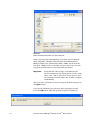
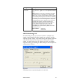
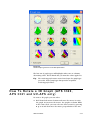
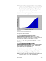
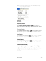
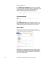
1
Particle Instruments Aerosol Instrument Manager® Software for Aerodynamic Particle Sizer® (APS ) Spectrometers TM User’s Manual P/N 1930064, Revision E April 2006 ® Aerosol Instrument Manager Software for Aerodynamic ® Particle Sizer (APS ) Spectrometers Introduction 1 Installing the Software 2 Getting Started 3 Software Procedures 4 TM User’s Manual Appendixes Manual History The following is a manual history of the Aerosol Instrument Manager Software for Aerodynamic Particle Sizer® (APSTM) Spectrometers User’s Manual (Part Number 1930064). Revision Date First Version A B C D E December 2001 May 2002 October 2002 April 2005 October 2005 April 2006 Warranty Part Number Copyright Address Email Address World Wide Web Site Telephone No. Fax No. 1930064 / Revision E / April 2006 Limitation of Warranty and Liability (effective July 2000) Seller warrants the goods sold hereunder, under normal use and service as described in the operator's manual, shall be free from defects in workmanship and material for (12) months, or the length of time specified in the operator's manual, from the date of shipment to the customer. This warranty period is inclusive of any statutory warranty. This limited warranty is subject to the following exclusions: ©TSI Incorporated / 2001–2006 / All rights reserved. TSI Incorporated / 500 Cardigan Road / Shoreview, MN 55126 / USA [email protected] http://www.tsi.com/ 1-800-874-2811 (USA only) or (651) 490-2811 (651) 490-3824 a. Hot-wire or hot-film sensors used with research anemometers, and certain other components when indicated in specifications, are warranted for 90 days from the date of shipment. b. Parts repaired or replaced as a result of repair services are warranted to be free from defects in workmanship and material, under normal use, for 90 days from the date of shipment. c. Seller does not provide any warranty on finished goods manufactured by others or on any fuses, batteries or other consumable materials. Only the original manufacturer's warranty applies. d. Unless specifically authorized in a separate writing by Seller, Seller makes no warranty with respect to, and shall have no liability in connection with, goods which are incorporated into other products or equipment, or which are modified by any person other than Seller. The foregoing is IN LIEU OF all other warranties and is subject to the LIMITATIONS stated herein. NO OTHER EXPRESS OR IMPLIED WARRANTY OF FITNESS FOR PARTICULAR PURPOSE OR MERCHANTABILITY IS MADE. TO THE EXTENT PERMITTED BY LAW, THE EXCLUSIVE REMEDY OF THE USER OR BUYER, AND THE LIMIT OF SELLER'S LIABILITY FOR ANY AND ALL LOSSES, INJURIES, OR DAMAGES CONCERNING THE GOODS (INCLUDING CLAIMS BASED ON CONTRACT, NEGLIGENCE, TORT, STRICT LIABILITY OR OTHERWISE) SHALL BE THE RETURN OF GOODS TO SELLER AND THE REFUND OF THE PURCHASE PRICE, OR, AT THE OPTION OF SELLER, THE REPAIR OR REPLACEMENT OF THE GOODS. IN NO EVENT SHALL SELLER BE LIABLE FOR ANY SPECIAL, CONSEQUENTIAL OR INCIDENTAL DAMAGES. SELLER SHALL NOT BE RESPONSIBLE FOR INSTALLATION, DISMANTLING OR REINSTALLATION COSTS OR CHARGES. No Action, regardless of form, may be brought against Seller more than 12 months after a cause of action has accrued. The goods returned under warranty to Seller's factory shall be at Buyer's risk of loss, and will be returned, if at all, at Seller's risk of loss. Buyer and all users are deemed to have accepted this LIMITATION OF WARRANTY AND LIABILITY, which contains the complete and exclusive limited warranty of Seller. This LIMITATION OF WARRANTY AND LIABILITY may not be amended, modified or its terms waived, except by writing signed by an Officer of Seller. Service Policy Knowing that inoperative or defective instruments are as detrimental to TSI as they are to our customers, our service policy is designed to give prompt attention to any problems. If any malfunction is discovered, please contact your nearest sales office or representative, or call TSI at 1-800-874-2811 (USA) or (651) 490-2811. v Software License (effective March 1999) 1. GRANT OF LICENSE. TSI grants to you the right to use one copy of the enclosed TSI software program (the “SOFTWARE”), on a single computer. You may not network the SOFTWARE or otherwise use it on more than one computer or computer terminal at the same time. 2. COPYRIGHT. The SOFTWARE is owned by TSI and is protected by United States copyright laws and international treaty provisions. Therefore, you must treat the SOFTWARE like any other copyrighted material (e.g., a book or musical recording) except that you may either (a) make one copy of the SOFTWARE solely for backup or archival purposes, or (b) transfer the SOFTWARE to a single hard disk provided you keep the original solely for backup or archival purposes. 3. OTHER RESTRICTIONS. You may not rent or lease the SOFTWARE, but you may transfer the SOFTWARE and accompanying written material on a permanent basis, provided you retain no copies and the recipient agrees to the terms of this Agreement. You may not reverse-engineer, decompile, or disassemble the SOFTWARE. 4. DUAL MEDIA SOFTWARE. If the SOFTWARE package contains multiple types of media, then you may use only the media appropriate for your single-user computer. You may not use the other media on another computer or loan, rent, lease, or transfer them to another user except as part of the permanent transfer (as provided above) of all SOFTWARE and written material. 5. U.S. GOVERNMENT RESTRICTED RIGHTS. The SOFTWARE and documentation are provided with RESTRICTED RIGHTS. Use, duplication, or disclosure by the Government is subject to the restrictions set forth in the “Rights in Technical Data and Computer Software” Clause at 252.22C-7013 and the “Commercial Computer Software - Restricted Rights” clause at 52.22C-19. 6. LIMITED WARRANTY. TSI warrants that the SOFTWARE will perform substantially in accordance with the accompanying written materials for a period of ninety (90) days from the date of receipt. 7. CUSTOMER REMEDIES. TSI’s entire liability and your exclusive remedy shall be, at TSI’s option, either (a) return of the price paid or (b) repair or replacement of the SOFTWARE that does not meet this Limited Warranty and which is returned to TSI with proof of payment. This Limited Warranty is void if failure of the SOFTWARE has resulted from accident, abuse, or misapplication. Any replacement SOFTWARE will be warranted for the remainder of the original warranty period or thirty (30) days, whichever is longer. 8. NO OTHER WARRANTIES. TSI disclaims all other warranties, either express or implied, including, but not limited to implied warranties of merchantability and fitness for a particular purpose, with regard to the SOFTWARE and the accompanying written materials. 9. NO LIABILTY FOR CONSEQUENTIAL DAMAGES. In no event shall TSI be liable for any damages whatsoever (including, without limitation, special, incidental, consequential or indirect damages for personal injury, loss of business profits, business interruption, loss of information or any other pecuniary loss) arising out of the use of, or inability to use, this SOFTWARE. vi Aerosol Instrument Manager® Software for APSTM Spectrometers Contents Manual History .................................................................... iv Warranty................................................................................v Software License (effective March 1999) ................................ vi About This Manual ............................................................... xi Purpose.................................................................................. xi Related Product Literature ..................................................... xi Getting Help........................................................................... xi Submitting Comments .......................................................... xii CHAPTER 1 Introduction ................................................... 1-1 How This Manual is Organized............................................ 1-2 Notations/Conventions Used in This Manual ...................... 1-2 CHAPTER 2 Installing the Software .................................... 2-1 Installation Requirements ................................................... 2-1 Installation.......................................................................... 2-2 CHAPTER 3 Getting Started ............................................... 3-1 Start the Program................................................................ 3-1 Open an Existing File .......................................................... 3-2 Change How Data is Viewed ................................................ 3-3 View Another Sample in the Same File ................................ 3-3 Playback (Review) Data Samples ......................................... 3-4 Select a Data Hot Spot ........................................................ 3-5 Delete/Undelete Samples .................................................... 3-6 Zoom In and Out on Data in a Graph.................................. 3-7 Print Information Displayed on the Desktop ........................ 3-7 Export Data to a File ........................................................... 3-8 Manually Export Data to a File......................................... 3-9 Automatically Export Data to a File ................................ 3-10 Arrange Open Windows ..................................................... 3-11 Quit the Program .............................................................. 3-12 CHAPTER 4 Software Procedures........................................ 4-1 How To Collect Sample Data ............................................... 4-1 Step A: Open a New APS File ............................................ 4-1 Step B: Review/Change/Set Up Spectrometer Properties.. 4-3 Step C: Start Data Collection............................................ 4-3 How To Set Up Properties for an APS Spectrometer ............. 4-4 APS Data Settings Tab ..................................................... 4-5 APS Scheduling Tab ......................................................... 4-7 APS Data Types Tab ......................................................... 4-9 APS Communications Tab .............................................. 4-10 Append Sample Data to an Existing APS File .................... 4-12 vii How To Change the 3D Graph Type (APS 3320, APS 3321 and UV-APS only) ........................................................... 4-12 How To Rotate a 3D Graph (APS 3320, APS 3321 and UV-APS only).................................................................. 4-13 Active Menus for an APS Spectrometer.............................. 4-15 File Menu ....................................................................... 4-15 Run Menu ...................................................................... 4-20 Playback Menu............................................................... 4-23 Format Menu ................................................................. 4-24 View Menu ..................................................................... 4-29 Sample Menu ................................................................. 4-40 Window Menu ................................................................ 4-42 Help Menu ..................................................................... 4-43 APPENDIX A Data Files, Project Files, and Stored Parameters .............................................................. 5-1 Data Files and Project Files ................................................. A-1 Project File Parameters........................................................ A-2 Saved Parameters ............................................................... A-3 APPENDIX B Accelerator Keys............................................ B-5 APPENDIX C Calculations Used for APS Spectrometers ....... C-1 APPENDIX D Stokes Correction for APS Spectrometers ...... D-1 APPENDIX E Sequence Files ............................................... E-1 Opening a File That is Part of a Sequence ........................... E-2 APPENDIX F Error Messages............................................... F-1 Index Reader’s Comments Figures 3-1 The Aerosol Instrument Manager Desktop and Selected Displays ........................................................................ 3-2 3-2 Playback Setup Dialog Box ............................................... 3-5 3-3 Use the Mouse to Directly View Values ............................. 3-6 3-4 Print Preview .................................................................... 3-8 3-5 The Export Parameters Box .............................................. 3-9 3-6 A Sample Export File ...................................................... 3-10 3-7 Two-Pane Layout of an APS File...................................... 3-11 4-1 Select an APS Filename When you Open a New File.......... 4-2 4-2 Data Settings Tab of the Properties Dialog Box ................. 4-5 4-3 Scheduling Tab of the Properties Dialog Box for the APS 3321 ...................................................................... 4-7 4-4 Data Types Tab of the Properties Dialog Box for an APS 3321 ...................................................................... 4-9 viii Aerosol Instrument Manager® Software for APSTM Spectrometers 4-5 The Communications Tab of the APS Properties Dialog Box................................................................... 4-11 4-6 The 3D Graph Type Box for a UV-APS Spectrometer ....... 4-13 4-7 The 3D Rotation Box ...................................................... 4-14 4-8 File Menu for an APS Spectrometer................................. 4-16 4-9 Print Preview Lets You See What Will be Printed Before You Print it.................................................................. 4-19 4-10 Run Menu for the APS Spectrometer............................... 4-20 4-11 Instrument Setup ........................................................... 4-22 4-12 Playback Menu ............................................................... 4-23 4-13 Format Menu for an APS File (A) When a Graph Window is Active, (B) When a Samples List Window is Active .... 4-24 4-14 The Y-Axis Dialog Box..................................................... 4-25 4-15 View Boundaries Dialog Box ........................................... 4-25 4-16 (A) The Graph Color Dialog Box, (B) The Table Color Dialog Box................................................................... 4-27 4-17 The Font Dialog Box ....................................................... 4-28 4-18 View Menu for (A) an APS Spectrometer, (B) a UV-APS Spectrometer ............................................................... 4-29 4-19 Units Selection Menu...................................................... 4-30 4-20 Aerodynamic Diameter Data Displayed in Number % Concentration ............................................................. 4-31 4-21 Aerodynamic Diameter Data Weighted by Mass .............. 4-33 4-22 Example of Table of Raw Data for Aerodynamic Diameter ..................................................................... 4-34 4-23 Event Data ..................................................................... 4-36 4-24 Instrument Status .......................................................... 4-37 4-25 Statistics Table ............................................................... 4-39 4-26 Sample Menu ................................................................. 4-41 4-27 Window Menu................................................................. 4-42 4-28 Help Menu...................................................................... 4-43 E-1 File Question? Dialog Box ................................................ 9-2 Tables 4-1 Descriptions of Data Setting Parameters for an APS Spectrometer ................................................................. 4-6 4-2 Descriptions of Scheduling Parameters for an APS Spectrometer ................................................................. 4-8 4-3 Descriptions of Data Types Parameters for an APS Spectrometer ................................................................. 4-9 4-4 Descriptions of Communications Parameters for an APS Spectrometer ............................................................... 4-11 4-5 Descriptions of 3D Rotation Box Parameters................... 4-14 4-6 Setup Fields for the APS 3320 and APS 3321 ................. 4-22 4-7 Display Options for Units ............................................... 4-30 Contents ix 4-8 Weight Options ............................................................... 4-32 4-9 Instrument Status Fields ................................................ 4-37 F-1 Error Messages................................................................. F-1 x Aerosol Instrument Manager® Software for APSTM Spectrometers About This Manual Purpose This is a user’s manual for the Aerosol Instrument Manager® Software as it applies to an Aerodynamic Particle Sizer® (APSTM) Spectrometer. Related Product Literature Model 3321 Aerodynamic Particle Sizer® (APSTM) Spectrometer manual (part number 1930092), TSI Incorporated Model 390069 Data Merge Software Module manual (part number 1930074), TSI Incorporated Getting Help To obtain assistance for this software or to submit suggestions, please contact Particle Instruments: TSI Incorporated 500 Cardigan Road Shoreview, MN 55126 USA Fax: (651) 490-3824 Telephone: 1-800-874-2811 (USA) or (651) 490-2811 E-mail: [email protected] xi Submitting Comments TSI values your comments and suggestions on this manual. Please use the comment sheet, on the last page of this manual, to send us your opinion on the manual’s usability, to suggest specific improvements, or to report any technical errors. If the comment sheet has already been used, mail or fax your comments on another sheet of paper to: TSI Incorporated Particle Instruments 500 Cardigan Road Shoreview, MN 55126 Fax: (651) 490-3824 E-mail Address: [email protected] xii Aerosol Instrument Manager® Software for APSTM Spectrometers CHAPTER 1 Introduction The Aerosol Instrument Manager® software is used to collect sample data from a TSI instrument and store the sample data in files. You can use the software to display data in graphs and tables, or view statistical information. You can print graphs and tables with the software, and you can also export data for use in other applications. There are a number of ways to navigate within the program. These include selecting items from the main menus, selecting icons from the toolbar, and selecting items from submenus (which you access by right-clicking the mouse button). Specific instructions are provided in the following chapters. The Aerosol Instrument Manager software is designed to be used with a variety of different TSI spectrometers. Aerodynamic Particle Sizer® (APSTM) Spectrometers Scanning Mobility Particle SizerTM (SMPSTM) Spectrometers Condensation Particle Counters (CPCs) Electrical Aerosol Detectors (EADs) Aerosol Electrometers This manual covers the use of the Aerosol Instrument Manager software with TSI APS spectrometers only. For information about software operation with other TSI spectrometers, refer to the appropriate manual. This manual assumes you have Microsoft ® Windows® (Windows 2000 or Windows XP) on your computer and that you are familiar with how Windows works. If you are not familiar with Windows, please refer to the information that came with it before you load and use this program. ® Microsoft and Windows are registered trademarks of Microsoft Corporation. 1-1 How This Manual is Organized This manual describes the Aerosol Instrument Manager software and includes information such as: Requirements for loading and running the software. The installation procedure that loads the program onto your computer. A “Getting Started” chapter that introduces basic software operations. “How to ...” information for using the program to operate and collect data with a specific spectrometer. Descriptions of the menus and menu items that are valid when collecting data with an APS or viewing data files from an APS. Appendixes that provide reference information associated with program operation. Notations/Conventions Used in This Manual 1-2 Throughout this manual when reference is made to “Windows,” it implies Windows® 2000 or Windows® XP operating system. Bold face type is used to indicate that you should perform the indicated action. For example “select the File menu” means that you should use the mouse and click on the menu called File. When instructions direct you to select items from a menu, a vertical bar (|) is used to separate the items you should select. For example, “select File|Properties|Scheduling” means you should click on the File menu, then select the Properties item, and then select the Scheduling tab. The term “active window” is used to refer to the window that is open on the desktop and is in focus. To verify which window is active, select the Window menu and note which item has a checkmark by it. You can make a window active by moving the pointer to that window and clicking the mouse button. Aerosol Instrument Manager® Software for APSTM Spectrometers CHAPTER 2 Installing the Software This chapter describes the installation requirements for the Aerosol Instrument Manager® software and the installation procedure. Note: If the Data Merge software is being used with the Aerosol Instrument Manager® software, it should be installed as listed: C:\Program Files\tsi\Data Merge Software Module\DataMerge.exe When installed correctly, Aerosol Instrument Manager activates the data merge software and the Data Merge icon appears ( ) on the main toolbar. For more information on the Data Merge software, please refer to the Model 390069 Data Merge Software Module manual (P/N 1930074). Installation Requirements To use this software we recommend a personal computer with the following minimum features, components, and software: A Pentium ® 586 processor or higher. A SVGA color monitor. Microsoft Windows ® 2000 or Windows® XP operating system. A hard drive large enough to accommodate Windows, the Aerosol Instrument Manager software, and data files. Note: The amount of disk space required depends on the number of samples you collect, the amount of information collected, and the sampling period. After you have collected a number of samples, you may want to look at the file size to estimate how much storage space you will be using. A CD-ROM drive. 256 MB or more of random access memory (RAM). ® Pentium is a registered trademark of Intel Corporation. Microsoft® and Windows® are registered trademarks of Microsoft Corporation. ® 2-1 A mouse. An RS-232 serial interface port for each instrument connected (in addition to the one that may be required for the mouse). A Microsoft Windows-compatible printer is optional. Installation Install the Aerosol Instrument Manager software as follows: 1. Shut down (exit) all programs/applications on the Windows desktop. 2. With the computer on and Windows running, insert the Aerosol Instrument Manager CD-ROM in your CD drive to run the autorun.exe from the CD. a. If AutoPlay is enabled on your PC, the setup program will begin automatically and the introduction screen will be displayed on the Windows desktop. b. If AutoPlay is not enabled, select Run from the Start menu and type: D:\autorun (where D is the letter corresponding to your CD drive) in the Open box and press OK. 3. Follow the instructions as the setup program runs. When setup is complete, you should read the readme.htm file. You should view the readme.htm file if one is available. This file contains important information that could not be included in this manual. If you decide not to read the file immediately, you can access the file later. It will be installed in the same directory as the application. 4. When the installation program finishes, remove the CD-ROM and store the CD in a safe place for later use. The setup program creates a directory (folder) called “Aerosol Instrument Manager” on your hard disk (assuming you accepted the default directory name). The directory contains the required program files and sample data files. The setup program also creates a new item in the Start Menu called “TSI” and an icon for the Aerosol Instrument Manager. Note: Before creating a TSI menu item, the setup program checks for an existing one. If one is present, it adds the icon only. 2-2 Aerosol Instrument Manager® Software for APSTM Spectrometers CHAPTER 3 Getting Started This chapter is designed to give you an introduction to the basic operation of the Aerosol Instrument Manager® software. Using it, you will: Start the program. Open an existing file (from the example files provided with the program). Change how data is viewed. View another sample in the same file. Playback (review) data samples in a “slide show” fashion. Select a data hot spot. Delete/Undelete samples. Zoom in and zoom out on data in a graph. Print information displayed on the desktop. Export data to a file. Arrange open windows. Quit the program. Start the Program To start the program, proceed as follows: From the Windows desktop, using the mouse, double-click the Aerosol Instrument Manager icon or press the Start menu and select All Programs|TSI|Aerosol Instrument Manager. The Aerosol Instrument Manager desktop appears as shown in Figure 3-1. 3-1 Data Display: Table Format Menu Options Tool Bar Data Display: Graph Format Samples List Figure 3-1 The Aerosol Instrument Manager Desktop and Selected Displays Statistics Table Open an Existing File 1. Select File|Open or on the toolbar. The “Open Instrument Associated Data Files” window opens. 2. When the “Open Instrument Associated Data Files” window appears, select the correct extension for the file you want to open in the “Files of type” box. For an APS, the file extension is .Axx, where xx indicates the APS model. 3. If necessary, browse for the drive/directory where data files are stored. (Example files are included with the program and were installed in the Aerosol Instrument Manager folder when the program was installed.) 4. Select the data file that you want to open and click Open. At least two windows open on the desktop: a window containing a graph of the sample data, and the Samples List window. 3-2 Aerosol Instrument Manager® Software for APSTM Spectrometers Note: If the file has been opened before, it may display more than one graph and/or table. The program remembers the windows that were open on the desktop when you last closed the file and reopens them when you access the file again. If the file contains a sequence of samples, you will be asked if you want to open all the files or just the one you originally chose. See Appendix E for information about sequence files. The Samples List window opens whenever you open a data file and remains open on the desktop as long as the data file is open. Closing the Samples List window closes the data file (and all its open windows). Change How Data is Viewed You can view APS data in tables or graphs and in several different formats (for example, data can be viewed by counts, concentration, etc.). The following procedure provides an example of how you can change how data is viewed. 1. Open one of the sample APS files as described in “Open an Existing File”. 2. With the graph window active on the desktop, open the View menu. 3. Use the mouse to select View|Weight|Mass. Notice the change in how data is displayed. (A checkmark next to one of the menu items means that a window for that selection is already open on the desktop. If you select a menu item that is already checked, the window containing that graph or table is brought to the top of the desktop and becomes the active window.) 4. Experiment with other views by making other windows active and selecting other options from the View menu to see how your selections change the data. View Another Sample in the Same File 1. To view another sample in an open file, select the icon (go forward one sample) from the toolbar. The data for the next sample of the currently active file replaces the data in all the open windows. 2. You can continue to step through the samples by pressing the icon until you reach the last sample. Getting Started 3-3 The sample currently displayed in the open window is highlighted in the Samples List window. Another method of changing the sample that is displayed in the open window on the desktop is by selecting the icon for that sample from the active Samples List window. You can use the following icons to display other samples: First Sample. Advance to the first sample. Previous Sample. Advance to the previous sample. Next Sample. Advance to the next sample. Last Sample. Advance to the last sample. Playback (Review) Data Samples You can display sample graphs and tables in a slide show fashion (to preview sample results or compare sample differences) as follows: 1. From the Samples List window, select the samples you want to play back using one of the following actions: Select Sample|Select All, to play back all samples. or Select individual samples using the mouse and the Ctrl key to highlight those samples you want to see. (You must select at least two samples.) or Select a group of samples by holding down the left mouse button and moving the mouse to “rubber band” (outline) the samples you want to select. Note: The Playback menu items and toolbar icons are only enabled when the Samples view is the active view. 2. When you have selected the samples you want to view, select Playback|Play. The setup box shown in Figure 3-2 appears. 3-4 Aerosol Instrument Manager® Software for APSTM Spectrometers Figure 3-2 Playback Setup Dialog Box 3. Select the sample viewing time and whether you want the samples displayed once or continuously. Playback begins immediately. For better viewing, it may be necessary to minimize the Samples List window. 4. You can pause the playback at any time by selecting Playback|Pause. Select Playback|Play to continue playback where you left off. You can stop playback at any time by selecting Playback|Stop. When you stop playback, you cannot restart it. Use Playback|Pause and Playback|Play if you want to stop and start playback. You can also control playback by using icons on the toolbar. The icons perform the following operations: Stop. Stop playback. Pause. Pause playback on current sample. Start. Start playback or restart playback. Select a Data Hot Spot When a graph is open on the desktop, you can find the values of a data point as follows: 1. Position the pointer on the bar, line, or peak (depending on the type of graph that is active). The pointer becomes a pointing hand. 2. Press the left mouse button to display the values. Figure 3-3, shows how the data values are displayed for an APS spectrometer (diameter and number concentration). Getting Started 3-5 Figure 3-3 Use the Mouse to Directly View Data Values Tip: After you have a data hot spot selected, use the arrow keys or the “>“ and “<“ keys to move the cursor right or left (from one value to the next), or grab the vertical bar and drag it to another location. Refer to Appendix B for a list of other keys or key combinations you can use to navigate and perform operations without using the mouse. Delete/Undelete Samples To delete samples from a file, you must first mark them for deletion and then either Close or Save the file. The following procedures will permanently delete samples from a file: Mark samples for deletion as follows: 1. Select the sample you want to delete from the Samples List window (you can select multiple samples). 2. Select Sample|Delete/Undelete Sample or on the toolbar. The samples will be shown as “Deleted.” However, they will not be permanently removed from the file until you Close or Save the file. 3-6 Aerosol Instrument Manager® Software for APSTM Spectrometers Save the file and permanently delete all samples marked for deletion: 1. With at least one sample marked for deletion in the active file, select File|Save. You will get a message stating: “Some samples have been marked for deletion. Do you want them permanently removed?” Click Yes to remove them or No to keep them. 2. Select Yes. The samples marked for deletion are permanently deleted. Note: If you attempt to close all the windows for the file or exit the program without saving the file, you will get a message asking whether you want to save changes to the file. Respond Yes and you will get the same message stating “Some samples have been marked for deletion. Do you want them permanently removed?” Respond Yes to delete the marked samples and No to close the file without deleting them. Zoom In and Out on Data in a Graph You can zoom in on data displayed in a graph as follows: 1. Use the mouse to position the cursor (pointer) at one corner of the area you want enlarged. 2. Press down on the left mouse button and drag the mouse to the opposite corner of the data you want enlarged. 3. Release the left mouse button. The area you selected is enlarged. 4. You can continue to zoom further by repeating steps 1 through 3. To Unzoom, select Format|Undo Zoom or enlarged area is returned to normal view. on the toolbar. The Print Information Displayed on the Desktop You can print the information displayed in the active window on the desktop as follows (you must have a printer properly installed): 1. With a graph or table window active on the desktop, select File|Print Preview or . 2. Review that what you see in the print preview window is what you want to print (an example is shown in Figure 3-4), and then Getting Started 3-7 select Print from the Preview box. The contents of the window are sent to your printer. You can immediately print a window without previewing it by selecting File|Print or from the toolbar. Figure 3-4 Print Preview Export Data to a File You can export data from an APS Aerosol Instrument Manager file in two ways: manually or automatically. 3-8 Aerosol Instrument Manager® Software for APSTM Spectrometers Manually Export Data to a File To manually export data (either a single sample of the file or multiple samples of the file) for use in another program (such as Microsoft Excel ®): 1. Select the sample or samples to be exported as follows: To export data from a single sample, display the sample data in an active window on the desktop. To export data from multiple samples, select (highlight) the samples you want to export from the Samples List window. 2. Select File|Export. An Export Parameters box appears. Figure 3-5 The Export Parameters Box. 3. Select the type of data you want to export as well as the format you want to export the data in. Data can be exported in a delimited text file and you can select ® Excel is a registered trademark of Microsoft Corporation. Getting Started 3-9 from three delimiters: tab, comma, or semicolon. The orientation of data can be either column or row. 4. After selecting the export parameters, press OK. 5. Select the drive/directory you want to export the data to and enter a filename. The system automatically adds the .txt file extension. 6. Press Save. 7. Figure 3-6 illustrates how an exported *.txt file is formatted for an APS Spectrometer. Figure 3-6 A Sample Export File Automatically Export Data to a File To export data automatically to a file for use in another program (such as Microsoft Excel): 1. Establish a connection to the APS spectrometer by choosing File|New, or File|New followed by Run|Connect to the APS. 3-10 Aerosol Instrument Manager® Software for APSTM Spectrometers 2. Select Run|Auto Export before you begin to collect data. Select the type of data you want to export as well as the format you want to export the data in, using the Export Parameters dialog box (see Figure 3-6). Data will be exported as it is collected. 3. Select Run|Start Data Collection. The data is exported to the file as it is collected. Arrange Open Windows When you have several windows open on the desktop it is helpful to arrange them for easier viewing. To arrange windows, select an item from the Window menu. You can arrange windows on your desktop horizontally, vertically, have them cascade, or arrange them in a predetermined auto-fit layouts. Refer to your Windows documentation for examples and more information for tile horizontal, tile vertical, and cascade layouts. Press the button (or Ctrl+L) in the toolbar for the four-pane layout or press the button (or Ctrl+K) for the two-pane layout as shown in Figure 3-7 for a spectrometer file. Figure 3-7 Two-Pane Layout of an APS File All of the program windows that are currently open on the desktop are listed at the bottom of the Window menu under the Close All Getting Started 3-11 item. To make a window active and bring it to the top of all windows, select the name of the window from the list of open windows. Quit the Program To end the program, select File|Exit. All windows and files open on the desktop are closed. If you have made changes to a file and have not yet saved it, you will be prompted to do so. 3-12 Aerosol Instrument Manager® Software for APSTM Spectrometers CHAPTER 4 Software Procedures Before using the information in this chapter, read Chapter 3. That chapter provides getting started information to help you understand the basics of how the program works. The subsections of this chapter provide: “How To...” information for: collecting sample data with an APS, setting up properties for an APS, changing the 3D graph type (APS 3320, APS 3321 and UV-APS only), and rotating a 3D graph (APS 3320, APS 3321 and UV-APS only). A description of all menus and menu items available when using the APS or viewing APS data files. How To Collect Sample Data There are three steps for collecting sample data from an APS. Step A: Open a new APS file Step B: Review/change parameters Step C: Start data collection Note: You can append APS sample data to an existing file. Refer to “Append Sample Data to an Existing APS File” below. Before you begin, make certain you have connected the TSI spectrometer to the computer and the instrument is running. Refer to the appropriate hardware instruction manual if necessary. Step A: Open a New APS File Select File|New or on the toolbar. The New Instrument and Associated Data Files dialog box (Figure 4-1) opens on your desktop. 4-1 Figure 4-1 Select an APS Filename When you Open a New File Before you can begin collecting data, you must select a filename (and, optionally, a location other than the Aerosol Instrument Manager folder). The default name will be “AIM1” for the first file you open, “AIM2” for the second file you open and so on. You can accept the default name or enter any name you choose. Important: Verify that the “Files of Type” box indicates the correct extension for the spectrometer you are using (.A10, .A12, .A20 or .A21). You do not need to enter an extension in the file name box. It will be assigned automatically. After you enter a filename (or if you accept the default name) press the Open button. If you get the following error message when opening a New file, press the OK button. This will open the Properties dialog box. 4-2 Aerosol Instrument Manager® Software for APSTM Spectrometers Verify the connection to the spectrometer and make certain the spectrometer is turned on. To verify the Com Port setting: 1. Check that the correct communications port was selected during program setup by clicking on the Test button. 2. If the test is unsuccessful, select another port and press the Test button again. Note: Most computers have only two active communications ports, COM1 and COM2. COM1 maybe used to connect the serial mouse, so COM2 is most likely available for the TSI spectrometer connection. 3. Once the test is okay, select OK to return to the desktop and the active window. Step B: Review/Change/Set Up Spectrometer Properties Before you begin sampling, you may want to review the Properties dialog to verify things such as correct start time, data settings, and so on. To view the properties dialog, select File|Properties or Run|Properties (or Ctrl+R) and select the various tabs to review each setting. Refer to “How To Set Up Properties for an APS Spectrometer” later in this chapter. Once you have set up the parameters, or verified they are correct, close the Properties dialog box and continue with step 3. Step C: Start Data Collection After you have completed the properties dialog, data collection begins at the “Start At Time” you set on the Properties dialog or immediately after you do one of the following: Select Run|Start Data Collection from the menu. Click Double-click the New Sample icon in the Samples List window. on the toolbar. When the program begins collecting sample data, the data is displayed in the windows that are open on the desktop. Note: When you start collecting APS data with the computer, the display menu of the APS 3320 or APS 3321 spectrometer is disabled. This prevents inadvertent changes to the properties you have set for sampling. APS Procedures 4-3 As each sample finishes, the data for the sample is stored and a new sample begins. When the last sample finishes, sampling stops, but the windows remain open. To stop data collection before all the samples are collected, do one of the following: Select Run|Finish Current Sample. Data collection stops after the current sample finishes. or Select Run|Abort Current Sample or on the toolbar to stop data collection immediately. When you select Abort Current Sample, the data collected for the current incomplete sample is discarded. How To Set Up Properties for an APS Spectrometer With an APS data file active on the desktop, access the Properties dialog box by selecting File|Properties or Run|Properties (or Ctrl+R). Note: An APS window must be active on the Aerosol Instrument Manager desktop to access the APS Properties menu item. The properties displayed in the Properties dialog box are either: The initial default properties as set by TSI or The default properties set by a user who selected File|Save Properties as Default after making changes to the Properties dialog box. Note: If you want to use the same settings the next time you access the properties dialog, remember to select File|Save Properties as Default after you have completed the Properties dialog. The Properties dialog box contains four tabs: Data Settings, Scheduling, Data Types, and Communications. Each is described below. Their content differs slightly for each APS model. The following paragraphs describe the settings for each tab of the Properties dialog box. 4-4 Aerosol Instrument Manager® Software for APSTM Spectrometers APS Data Settings Tab The Data Settings tab lets you specify parameters that are applied to the data when you view or export it. The actual data in the file is not affected by these parameters. Figure 4-2 Data Settings Tab of the Properties Dialog Box APS Procedures 4-5 Table 4-1 Descriptions of the Data Setting Parameters for an APS Spectrometer Setting Description Dilution/ Efficiency File Use this list box to select an efficiency file that you want to use to condition sample data. This efficiency file is automatically loaded and used in calculating sample data. The file must be located in the folder created during program setup where the software is installed (usually Aerosol Instrument Manager folder). The file must also have an extension of “.exx” where xx reflects the instrument the file is used with. (For example, 00001to1.e21 is an efficiency file for the 3321 APS, 00001to1.e20 is an efficiency file for the 3320 APS, 00001to1.e10 is an efficiency file for the 3310 APS.) The dilution files provided with the software are for use with TSI 3302A Diluter(s). Spectrometer: Particle Density (g/cc) Spectrometer: Apply Stokes Correction All APS Enter the particle density (in g/cc) you want the software to use when calculating the surface area and mass concentrations. The default is 1.000000. (The geometric diameter is calculated first and then the surface area and mass are derived, assuming spherical particles). If you enter a value other than 1.000000, you are changing the Y axis on the graphs; the shape of the distribution remains the same. All APS Check this box if you want Stokes correction to be applied to the aerodynamic diameter data. (applying this correction improves the accuracy of particle sizing for particles with a density <0.9 and >1.1.) Stokes correction is described in Appendix D. The view boundaries may change when Stokes correction is applied. If the density is >1.1, the maximum size is less than 20.535. The view boundary will move to the new maximum size if the current upper boundary is larger than the Stokes adjusted maximum size. Likewise, the lower view boundary will change when the density is <0.9 and the selected view boundary is less than the Stokes corrected minimum size. Spectrometer: 4-6 All APS Aerosol Instrument Manager® Software for APSTM Spectrometers Setting Description Phantom Count Correction Check this box if you want Phantom Count correction to be applied to the aerodynamic diameter data. Note: Phantom counts can be created by the small particle processor of the APS 3310 or APS 3310A. When only one pulse is detected per particle, a pulse generated by another particle can cause a randomly sized particle to be recorded. Particles in the range of 5.2 to 15.4 µm are measured by both the large and small particle processors. Phantom count correction estimates the number of phantom particles by calculating the difference between the number of counts detected by each processor within the overlapping size channels. This difference is subtracted from each channel of data in the small particle processor. Spectrometer: APS 3310, APS 3310A APS Scheduling Tab The Scheduling tab lets you select the number of samples, the length of each sample, how often samples are collected, and the start time for the sample. You cannot change the sample length for a file that already has data. If you want to change the sample length, you must start a new file. Figure 4-3 shows an example Properties dialog box showing the Scheduling tab. A description of each parameter follows. Figure 4-3 Scheduling Tab of the Properties Dialog Box for the APS 3321 APS Procedures 4-7 Table 4-2 Descriptions of Scheduling Parameters for an APS Spectrometer Parameter Sample length (Sec) Description This is the amount of time (in seconds) that data will be collected from the TSI spectrometer for each sample. The maximum value allowed is 65535 (18 hours, 12 min., 15 sec.). Number of Samples This is the total number of samples you want to collect. The maximum value allowed is 65535. Total Sample Time This field is calculated by the software and shows the total sample time based on the values you entered in the Sample Length and Number of Samples boxes. The value is displayed in hours, minutes, and seconds. Scheduled Select only once to collect one set of samples. For continuous monitoring, select Repeat Every and then select the hours and minutes between samples. The intersample time should be longer than the Total Sample Time to include the overhead time that is needed for file handling. Synchronize Sample Timing If this box is checked, the value in the Sample length box is the elapsed time of the sample. In this mode, Aerosol Instrument Manager calculates the APS 3310’s sample length based upon known timing overhead for this instrument. If this box is unchecked, the value in the Sample length box is used as the sample length. If this box is checked, the elapsed time for a sample will include overhead. Note: The typical elapsed time for the APS 3310 to complete a single sample takes an additional 8% of the time set in Sample Length field of the properties dialog box. For example, a sample length of 60 seconds would take 65 seconds to complete. Spectrometer: Start At Time APS 3310 If you don’t check this box, sampling begins as soon as you select Start Data Collection. If you want to select a start time, check the box and enter the clock time at which you want sampling to begin. The program uses a 12-hour or 24-hour clock, depending on how your PC is set up. If your PC is set up to use a 12-hour clock, you must indicate if the time is am or pm by unchecking or checking the PM box. The reference time for the program is the time at which your computer is set. 4-8 Aerosol Instrument Manager® Software for APSTM Spectrometers Files of Sample Sessions That Run Past Midnight The files for sample sessions that run past midnight are handled differently than those that start and stop on the same date. In this case a sequence of files is created, with each file in the sequence given a unique filename extension identifying its proper order. Appendix E provides a complete description of sequence files including how to access a file that is part of a sequence. APS Data Types Tab The Data Types tab lets you set up the type of data to be collected. The type of data that can be collected varies depending on which TSI spectrometer you are using. Figure 4-4 Data Types Tab of the Properties Dialog Box for an APS 3321 Table 4-3 Descriptions of Data Types Parameters for an APS Spectrometer Type Description Aerodynamic Diameter Select the data you want collected. You can collect channel data*, raw data** or both. Spectrometer: APS 3310 APS 3310A APS 3320 APS 3321 UV-APS. *The APS 3310 will always collect channel data. **The UV-APS will not collect raw data. APS Procedures 4-9 Type Description Side Scatter You can have the program display channel data, raw data* or both. Spectrometer: APS 3320, APS 3321 and UV-APS *The UV-APS will not collect raw data. Sample Mode Select the sampling mode you want to use: Summing or Correlated. You may only select one. Correlated mode does not collect raw data. Correlated mode collects Side Scatter vs. Aerodynamic Diameter data. When correlated mode is selected, it is recommended to use 38400 baud rate in the APS to transfer data. The data display updates once every second in Summing mode and once every four seconds in Correlated mode. The number concentrations measured by the 3321 APS are the same in summing mode and in correlated mode for all size channels except for channel No. 1 which includes particles smaller than 0.523 μm. In the Aerosol Instrument Manager software, the number concentration in channel No. 1 (< 0.523 μm) in summing mode includes event 1s, thus is always higher than that in correlated mode which doesn’t include event 1s. In the display on the front panel of the instrument, the number concentrations in channel No. 1 are the same in summing mode and in correlated mode because they both include event 1s. Spectrometer: APS 3320 and APS 3321 Side Scatter vs. Aerodynamic Diameter Collect Side Scatter vs. Aerodynamic Diameter correlated data. Fluorescence vs. Aerodynamic Diameter Collect Fluorescence vs. Aerodynamic Diameter correlated data. Fluorescence vs. Side Scatter Collect Fluorescence vs. Side Scatter correlated data. Resolution Determines the resolution of the sample data for Fluorescence and Side Scatter measurements. Choose from 2, 4, 8, 16, 32, 64 divisions. Spectrometer: Spectrometer: Spectrometer: Spectrometer: UV-APS only UV-APS only UV-APS only UV-APS only APS Communications Tab The Communications tab, Figure 4-5, lets you set up and test the communications port and is only available when you open a new file. The parameters of the communications tab are identical for all spectrometers. 4-10 Aerosol Instrument Manager® Software for APSTM Spectrometers Figure 4-5 The Communications Tab of the APS Properties Dialog Box Table 4-4 Descriptions of Communications Parameters for an APS Spectrometer Property Description Available Ports Lists the ports available on your computer system and lets you select the port that is connected to the TSI spectrometer. Test Button After you select a Com Port, press this button and the software will try to read data from the spectrometer to verify that you have selected the correct port and have a working connection. Test Results Reports the results of the test whether it is connected or not. APS Procedures 4-11 Append Sample Data to an Existing APS File To append sample data to an existing APS file: 1. Open the file that you want to append data to. 2. Select Run|Connect to the APS. If a connection is not found, the Properties dialog opens with the Communications tab selected to let you establish a connection with the APS spectrometer. Once there is a valid connection, the New Sample icon appears in the Samples List window and the Start Data Collection button is enabled on the toolbar. You can then append samples to the data file (see Step C: Start Data Collection, above). How To Change the 3D Graph Type (APS 3320, APS 3321 and UV-APS only) You can change the 3D graph type by selecting Format|Graph Type from the menu bar. Figure 4-6 shows the graph type dialog box. Pick a graph type which best represents your data. Note: A window with a 3D graph must be active on the desktop to change the graph type. Refer to the descriptions of the View menu later in this chapter. 4-12 Aerosol Instrument Manager® Software for APSTM Spectrometers Figure 4-6 The 3D Graph Type Box for a UV-APS Spectrometer The last row of graph types will highlight either rows or columns, alternating colors. Select which axis you want the colors applied to. Tip: The rendering performance varies based upon the graph type you select. Pick a graph type that provides acceptable rendering performance. How To Rotate a 3D Graph (APS 3320, APS 3321 and UV-APS only) To rotate a 3D graph, you can either: Hold down both mouse buttons and move the mouse to rotate the graph. As you move the mouse, the graph is redrawn. While in the rotate mode, you can select one axis to rotate by pressing x, y, or z, and then move the mouse perpendicular to the axis. APS Procedures 4-13 Tip: The 3D graphs take a lot of CPU processing to render the image. If you have experienced poor performance while rotating the graph using the mouse, then make sure the “Enable Rotation Preview” check box is not checked. With the check box cleared, you will only be shown a wire frame of the 3D plot cube. Use the 3D graph rotation dialog box shown in Figure 4-7. This dialog box allows you to enter the x, y, z rotation of the 3D graph. Figure 4-7 The 3D Rotation Box Table 4-5 Descriptions of 3D Rotation Box Parameters Parameter X, Y, Z Description Shows the current rotation of the 3D graph in degrees. By clicking on these edit boxes, you are able to specify a rotation view. Reset Resets the X, Y, Z parameters back to their original values when you entered this dialog box. Defaults Sets the X, Y and Z values to the default view. Interactive Rotation Preview When this box is checked, you can interactively see the 3D graph while rotating it using the mouse method described above. When this box is not checked, you will only see a wire frame while rotating the 3D graph. Note: If you experience poor performance while rotating a graph when this box is checked, use the wire frame method for rotating the graph. 4-14 Aerosol Instrument Manager® Software for APSTM Spectrometers Active Menus for an APS Spectrometer This section describes the various functions available for an APS through the menus on the Aerosol Instrument Manager desktop. The Menus include: File, Run, Playback, Format, View, Sample, Window, and Help. Which menus are available depends on the operation you are currently performing on the desktop. In addition to the menus, a toolbar (located just beneath the desktop menus) is available to provide shortcuts to many of the functions in the menus. You can hide the toolbar if you want to enlarge the desktop, see the description of the View Menu, below. Note: All menus and the menu items are described below. Depending on the operation you are currently performing and the window that is active on the desktop, the menu may appear different than shown, i.e., some menu items may not be available. File Menu The items of the File menu are used to open, save, and recall files and perform other program operations. APS Procedures 4-15 Figure 4-8 File Menu for an APS Spectrometer New Select File|New or on the toolbar to open a new file and prepare to collect sample data. After you select New, you are prompted to enter a filename. Accept the default filename or enter any filename you chose, then select OK. A Samples List window and a graph window open on the desktop with the filename you entered and you are ready to start collecting data. Refer to “How To Collect Sample Data” for a complete description. Open Select File|Open or on the toolbar to open an existing file. By default, sample files are stored in the same directory as the Aerosol Instrument Manager program. All files will automatically be given the appropriate filename extension according to the spectrometer model you are using (see above description). If you store data files in another directory or on another drive, you must first display the file pathname in the Open window before you can select and open it. 4-16 Aerosol Instrument Manager® Software for APSTM Spectrometers Note: When opening files for sample sessions that run past midnight, refer to the description of Sequence Files in Appendix E and for information on how the files are opened. When the file opens, a window opens on the Aerosol Instrument Manager desktop containing data from the first sample in the file. You can have many samples and many files open on the desktop at the same time. Only one window, however, is the active window. Close Select File|Close to close a file (and all the windows associated with it). If windows are open on the desktop from more than one file, Close will close only those windows associated with the file whose window is currently active. If you attempt to close a file that has been changed but not saved, you will be prompted to save the changes before closing the file. If you have marked a sample or samples for deletion, but have not saved the file, you will get the following message: “Some samples have been marked for deletion. Do you want them permanently removed?” If you click Yes the sample files marked for deletion are permanently deleted. If you click No the samples marked for deletion are not deleted. They are saved, and are no longer marked for deletion. Save Select File|Save or on the toolbar to save sample data to a file. If you have marked a sample or samples for deletion, but have not saved the file, you will get the following message: “Some samples have been marked for deletion. Do you want them permanently removed?” If you click Yes the sample files marked for deletion are permanently deleted. If you click No the samples marked for deletion are not deleted. They are saved, and are no longer marked for deletion. Save As Select File|Save As to save data in an existing file to a new filename. (The file contents are duplicated to the new filename. If you want to delete the original filename, use Windows Explorer to do so.) After you select Save As, you can select a drive/directory. You can use the same filename if you save the file to another APS Procedures 4-17 drive/directory, but if you want to save the file to the same directory, you must give it a new name. Do not add the filename extension. It is added automatically when you select Save. Import (APS 3310 only) Select File|Import to import data into the program from previous versions of the software. For example, to import a file from the APS 3310, navigate to the directory that contains the 3310 file and select the file you want to import. Export Select File|Export to export data (either a single sample or multiple samples of a file) for use in another program. Data is exported in a delimited text file. Refer to “Export Data to a File” in Chapter 3 for information. Properties… Select File|Properties to set the parameters used by the Aerosol Instrument Manager software to collect sample data. The Properties dialog box has four tabs. The parameters that can be set for each spectrometer on each tab are described in “How To Collect Sample Data” earlier in this chapter. Save Properties As Default Select File|Save Properties as Default if you want the properties for the currently selected sample to be the default properties for new samples. Set to Original Defaults Select File|Set to Original Defaults if you want to return all setting in the Properties dialog box to the original settings as provided by TSI. Print Select File|Print to print the active window on the desktop. If you want to preview the output before printing it, select File|Print Preview. Refer to your Windows documentation for information about the Print dialog box. 4-18 Aerosol Instrument Manager® Software for APSTM Spectrometers Print Preview To avoid printing something you don’t want, select File|Print Preview to see what your printed output, Figure 4-9, will look like before selecting Print. Print Setup Select File|Print Setup to set up the printer for printing. Refer to your Windows documentation and your printer’s documentation for information about setting the printer parameters. Figure 4-9 Print Preview Lets You See What Will be Printed Before You Print it List of Recently Accessed Files Between the Printer Setup and Exit menu items is a list of the most recently accessed data files (a maximum of four files is displayed). These are accessed from the menu by selecting File|1, 2, 3, or 4. The list provides a shortcut to these files so you can bypass the Open command. To open one of the files listed, use the mouse to highlight it and then click the left mouse button. The file opens on the desktop. Exit Select File|Exit to end the program. APS Procedures 4-19 Run Menu The items available under the Run menu are used to start and stop data collection. Figure 4-10 Run Menu for the APS Spectrometer Start Data Collection With a new file open on the desktop, select Run|Start Data Collection or on the toolbar to begin collecting sample data. Samples are collected according to the sample length, number of samples, scheduled times and other parameters set in the tabs of the Properties dialog (see earlier in this chapter). Note: If a start time is set, this menu item (and its associated icon) is disabled. Once you select Start Data Collection, sampling begins immediately. As data is collected, it is displayed in the open windows. Finish Current Sample Select Run|Finish Current Sample when you want to stop collecting sample data prematurely (Before the sampling period ends as set in the Properties dialog.). When you select this item, the current sample is allowed to finish before sampling ends. Abort Current Sample Select Run|Abort Current Sample or from the toolbar when you want to stop collecting sample data immediately. When you select this item, sampling stops and the data for the current sample is discarded. 4-20 Aerosol Instrument Manager® Software for APSTM Spectrometers Connect to the APS Select Run|Connect to the APS if you want to connect an open data file to append more samples to the file. If a connection is not found, the Properties dialog opens with the Communications tab selected to let you establish a connection with the APS. Once there is a valid connection, the New Sample icon appears in the Samples List window and the Start Data Collection button is enabled on the toolbar. You can then append samples to the data file. Disconnect from the APS Select Run|Disconnect from the APS to disconnect an open file and stop collecting samples. You cannot append samples to a file unless it is connected to the APS spectrometer. Once the APS is disconnected, the New Sample icon is removed from the Samples List window and the Start Data Collection button is disabled. Auto Export Select Run|Auto Export to automatically export the data as it is collected to a file. When you select this menu item, an Export Dialog box opens. Select the type of data you want to automatically export, then press OK. Note: You cannot auto-export raw data or export data in columns. See “Export Data to a File” in Chapter 3. Properties… This menu item provides a shortcut to the same Properties menu item listed under the File menu and appears here for convenience. Select Run|Properties to display the Properties dialog that lets you set the parameters used by the Aerosol Instrument Manager software to collect sample data. The parameters that can be set are described earlier in this chapter. APS Procedures 4-21 Instrument Setup… (APS 3320 and APS 3321 only) Select Run|Instrument Setup to bring up a dialog box that allows you to change instrument settings. Figure 4-11 Instrument Setup Table 4-6 provides an explanation of each field in the Instrument Setup dialog box. Table 4-6 Setup Fields for the APS 3320 and APS 3321 Setup Parameter 4-22 Description Laser Turn the laser on and off. Pump Turn the pumps on and off. Front Panel Enable Enable or disable the instrument front panel display. Instrument Sound Turn on and off the beeping sound that is activated when the High Concentration limit is exceeded APD Autocal Enables the Avalanche Photodetector (APD) temperature compensation algorithm when set to On. When set to Off, the APD voltage will not change with the APD temperature. This setting will always be enabled when the instrument is first powered on. High Concentration Threshold The limit of the number of particles per cc. The range is from 0 – 65535. When this limit is exceeded, a status flag will be set, the LED on the instrument will light up, and the instrument will beep if the sound is set to On. Analog Output BNC Mode Sets the mode and range for the analog output BNC on the back panel of the APS. For a more detailed description, refer to the Model 3320 or 3321 Aerodynamic Particle Sizer instrument manual. Aerosol Instrument Manager® Software for APSTM Spectrometers Playback Menu The Playback menu appears only when a Sample List window is active on the desktop. Its purpose is to allow you to display graphic and table windows in series, like a slide show, so that you can compare samples or view a series of samples. Figure 4-12 Playback Menu Refer to “Playback (Review) Data Samples” in Chapter 3 for instructions. Play Select Playback|Play or from the toolbar to display the control window for playing the samples you selected. First select the time you want each sample displayed (full speed, 0.5, 1.0. 2.5 or 5.0 seconds). Then select whether to view the samples once or continuously. As soon as you select Play Once or Play Continuously the open views for the first sample you selected are displayed for the specified period, then the views for the second sample are displayed, and so on until all the samples selected have been displayed. If you selected Play Continuous from the Playback Setup dialog box, the series repeats itself indefinitely. Pause Select Playback|Pause or from the toolbar to interrupt the playback of the samples. This feature lets you stop playback to view the data of an interesting sample without canceling the playback of all selected samples. When you want to start playback again, select Playback|Play. Stop Select Playback|Stop or from the toolbar to end sample playback before all samples have been displayed. If you select Stop and you want to restart sampling, you must select Playback|Play, select the time you want each sample displayed, select play once or continuously, and begin displaying samples from the first selected sample. APS Procedures 4-23 Format Menu The Format menu has many variations depending on the active window. The menu items of the Format menu let you control how information is presented in tables and graphs including: graph type, grid lines, font, color, etc. When a Sample List window is active on the desktop, the menu items of the Format menu let you determine how items in the Sample List window are displayed. You can select large or small icons, or list the samples with or without details. Details include: date, pathname, and title of the sample. When a window is active on the desktop, you can display the Format menu items (plus other menu items) by placing the cursor in the window and clicking the right mouse button. (A) (B) Figure 4-13 Format Menu for an APS File (A) When a Graph Window is Active, (B) When a Samples List Window is Active Y Axis This menu item is available only when a graph window is active on the desktop. Select Format|Y Axis to select the way the Y axis is displayed, see Figure 4-14. By default, the graphs display in normal/auto scale. You can select Auto or Fixed scale and either log or normal scale. To display in logarithmic scale, check the Log Scale box. If you select Fixed Scale, you must enter a minimum and/or maximum number (you do not need to enter both). 4-24 Aerosol Instrument Manager® Software for APSTM Spectrometers Figure 4-14 The Y-Axis Dialog Box View Boundaries Select Format|View Boundaries to display the View Boundaries dialog box, as shown below. Use the dropdown boxes to select the upper and lower boundaries of the data’s size range that will be viewed. Data is displayed between the selected boundaries and statistics are computed based on the range of data between the boundaries. Select Set to Mx View to include all data. In the graph window, you can drag view boundaries by positioning the cursor on the boundary you want to change, clicking the left mouse button, and dragging the view boundary to the new location. Figure 4-15 View Boundaries Dialog Box APS Procedures 4-25 Graph Type (2D) Select Format|Graph Type to select the type of graph to display in the active window. The options are bar, line, or area. If the Graph toolbar is visible, you can select the option using the appropriate icon. Display graphs using bars. Display graphs using lines. Display graphs showing area. Grid Lines Select Format|Grid Lines to select the lines for the graph in the active window. The options are horizontal, vertical, both or none. If the Graph toolbar is visible, you can select the option using the appropriate icon. Display graphs with no grid. Display graphs with a horizontal grid. Display graphs with a vertical grid. Display graphs with both horizontal and vertical grids. Color Select Format|Color to change the colors used to display items in the active window. When you select Format|Color, the Graph Color or Table Color window opens depending on the active window on the desktop (Figure 4-16 shows both). These windows include a preview screen, a drop down list and a color palette. From the drop down list, select the name of the item you want to modify. The current color for that item is indicated in the color palette. Use the mouse to point to the new color for that item and click the left mouse button to select it. The preview screen then displays the item in the new color. 4-26 Aerosol Instrument Manager® Software for APSTM Spectrometers (A) (B) Figure 4-16 (A) The Graph Color Dialog Box, (B) The Table Color Dialog Box Select items from the drop down list and colors as desired. When finished, press OK; the colors you selected will be used from that point on in all graphs and/or tables. The items you can select for windows containing graphs are: Window Background Plot Area Background Labels Axis Data Channel View Boundaries Data Hotspot Lines APS Procedures 4-27 The items you can select for windows containing tables are: Window Background Cell Text Grid Color Cell Background Fixed Area Text Font Select the Format|Font menu to change the style and size of the text in all graphs or tables. Select Format|Font|Style… to select a new font or change the font style, see Figure 4-17. You can select any font and font style available on your computer. The preview box lets you see what the text will look like before you implement it by selecting OK. Figure 4-17 The Font Dialog Box To change the font size, select Format|Font|Small, Medium, or Large (the default is Medium). To change the text size without using the menus, select the icon from the toolbar. Each time you select the icon the text size changes to the next text size. (Rotation is from small to medium to large.) Rotation (APS 3320, APS 3321 and UV-APS only) When a 3D graph is active, select Format|Rotation to bring up a dialog box that allows you to enter the x, y, and z rotation of the 3D 4-28 Aerosol Instrument Manager® Software for APSTM Spectrometers graph. See “How To Rotate a 3D Graph” earlier in this chapter for a figure and description of the dialog box. Graph Type (3D for APS 3320, APS 3321 and UV-APS only) Select Format|Graph Type to bring up a dialog box that allows you to choose the graph type that best represents your data. See “How To Change the 3D Graph Type” earlier in this chapter for a figure and description of the dialog box. Undo Zoom Select Format|Undo Zoom to return a graph to its “normal” viewing size after you have zoomed in on a portion of the graph. See “Zoom In and Out on Data in a Graph” in Chapter 3. View Menu The list of items in the View menu depends on which windows are open on the desktop and which one is active. The View menu lets you select the sample windows to open on the desktop and select parameters to view in those windows. A checkmark next to an item indicates the item has already been selected. Look under the Windows menu to find the item and make it the active window. (A) (B) Figure 4-18 View Menu for (A) an APS Spectrometer, (B) a UV-APS Spectrometer APS Procedures 4-29 Units The Units menu item appears when a graph or data table window is active on the desktop (except a raw data or event data window). This menu item works in conjunction with the Weight menu item, and lets you choose the units in which data will be displayed. Unit selections include: Figure 4-19 Units Selection Menu The currently selected unit is marked with a check mark. This was set by selecting View|Units|dW/dlogDp. Table 4-7 gives an explanation of each unit. Table 4-7 Display Options for Units 4-30 View Units Description dW/dlogDp This option displays differential or normalized particle size distribution, normalized to one decade of particle size. This normalized concentration format allows particle size distributions to be compared regardless of the channel resolution. dW/dlogDp = dW × resolution in channels/decade. W represents the weighting of the distribution, which can be N (number), S (surface area), V (volume), or M (mass). Concentration (dW) This option displays interval particle size distributions. The concentration in any channel represents the concentration within the particle size boundaries for that channel. W represents the weighting of the distribution, which can be N (number), S (surface area), V (volume), or M (mass). % Concentration This option displays each particle size channel as a percentage of the total particle concentration. Cumulative Conc. This option displays the particle concentration in a cumulative or summed format. Each particle size channel represents the total concentration of particles measured below its upper size boundary. Cumulative % Conc. This option is the same as Cumulative Conc., but displayed as a percentage of the total concentration. Aerosol Instrument Manager® Software for APSTM Spectrometers View Units Description Counts/Raw Counts Counts/Raw Counts are the lowest level of data representation, raw detected particle counts put into channels by size, but without any corrections. Mapping of particle size within the program can cause single counts to be split across two channels. Figure 4-20 shows an aerodynamic diameter graph displayed in number % concentration using data from a 3321 APS spectrometer. Figure 4-20 Aerodynamic Diameter Data Displayed in Number % Concentration Weight The Weight menu item appears only when an Aerodynamic Diameter Graph window is active on the desktop. This menu item works in conjunction with the Units menu item and lets you choose how to “weight” the units that are displayed. You can select: • Number • Surface • Mass The currently selected weight is marked with a check mark. Table 4-8 gives an explanation of each unit. APS Procedures 4-31 Table 4-8 Weight Options View Units Description Number Number represents the total number of particles per unit volume of air sampled (i.e., number concentration expressed as #/cm3). Number concentration is the primary measurement of the APS system. The spectrometer is sensitive to the number of particles in the aerosol sample as opposed to the particle mass, color, shape, composition or other characteristic. The distributions of surface area or mass concentrations of the particles are calculated based on the particle number distribution. The number concentration, dN, measured by the APS is the concentration of particles in a given channel. The normalized number concentration, dN/dlogDp, is calculated by dividing dN by the geometric width of the size channel. Surface Surface represents the total surface area of the particles per unit volume of air sampled (i.e., surface area concentration expressed as nm2/cm3). The surface area concentration calculation assumes that all the particles are perfect spheres. Surface area concentration is calculated by: 2 dS=dN ⋅ π Dp , where Dp is the geometric midpoint of the particle size channel. Note that the APS measures the aerodynamic diameter of particles. The relationship between the geometric diameter (Dp) and aerodynamic diameter (Da) is given in Appendix C. The normalized surface concentration based on geometric diameter is: 2 dS/dlog Dp=dN/dlog Dp ⋅ πDp . Mass Mass represents the total mass of the particles per unit volume of air sampled (i.e., mass concentration expressed as µg/cm3). The mass concentration calculation assumes that all the particles are perfect spheres with the density defined in the Run|Properties dialog for the instrument. Mass concentration is calculated by: 3 dM=dN ⋅ (π/6)Dp ρ, where Dp is the geometric midpoint of the particle size channel and ρ is the density. Note that the APS measures the aerodynamic diameter of particles. The relationship between the geometric diameter (Dp) and aerodynamic diameter (Da) is given in Appendix C. The normalized mass concentration based on geometric diameter is: 3 dM/dlogDp=dN/dlogDp ⋅ (π/6)Dp ρ. In many of the tables, the values for all three weightings are supplied in tabular format. 4-32 Aerosol Instrument Manager® Software for APSTM Spectrometers Note: Surface and Mass weighting calculations assume that all the particles are spherical. Mass calculations also assume that all particles have the density defined in the properties dialog for the instrument. However, comparisons to methods that measure particle surface or mass directly may give results different from those calculated by the software. Figure 4-21 shows sample aerodynamic diameter data in units of cumulative concentration weighted by mass. Figure 4-21 Aerodynamic Diameter Data Weighted by Mass Aerodynamic Channel Data Select View|Aerodynamic Channel Data|Graph or View|Aerodynamic Channel Data|Table to open a window displaying the aerodynamic diameter data of the active sample. (By default, the active sample is the first sample in the file.) Aerodynamic Raw Data (APS 3310, APS 3320 and APS 3321 only) Select View|Aerodynamic Raw Data|Graph or View|Aerodynamic Raw Data|Table to open a window displaying the aerodynamic raw data of the active sample. (By default, the active sample is the first sample in the file.) The raw data, which is available only for the APS 3310, APS 3320 and APS 3321, consists of 1024 channels of aerodynamic diameter data that the APS collected. This data is converted, using a calibration curve, into equally sized and spaced bins over the measurement range of the spectrometer to give channel data. Note: If you did not collect this raw data initially, as specified in the Properties window, then no data can be displayed. APS Procedures 4-33 Figure 4-22 illustrates an aerodynamic diameter raw data table. Figure 4-22 Example of Table of Raw Data for Aerodynamic Diameter Side Scatter Channel Data (APS 3320, APS 3321 and UV-APS) Select View|Side Scatter Channel Data|Graph or View|Side Scatter Channel Data|Table to open a window displaying the side scatter data of the active sample. (By default, the active sample is the first sample in the file.) Side Scatter Raw Data (APS 3320 and APS 3321 only) Select View|Side Scatter Raw Data|Graph or View|Side Scatter Raw Data|Table to open a window displaying the side scatter raw data of the active sample. (By default, the active sample is the first sample in the file.) The raw data for the APS 3320 consists of 256 channels of side scatter data; the raw data for the APS 3321 consists of 64 channels. This data is converted, using a calibration curve, into equally sized and spaced bins over the measurement range of the spectrometer to give channel data. Note: If you did not collect this raw data initially, as specified in the Properties window, then no data can be displayed. 4-34 Aerosol Instrument Manager® Software for APSTM Spectrometers Correlated Data (APS 3320 and APS 3321 only) Select View|Correlated Data|Graph to open a window that displays the correlated data of the active sample. (By default, the active sample is the first sample in the file.) You can view correlated data (View|Correlated Data) as a graph or a table. Note: If you did not collect correlated data, as specified in the Properties window, then no data can be displayed. Side Scatter vs Aero. Diameter (UV-APS only) Select View|Side Scatter vs Aero. Diameter|Graph to open a window that displays a three-dimensional graph of the Side Scatter vs. Aerodynamic Diameter data of the active sample. (By default, the active sample is the first sample in the file.) You can view Side Scatter vs. Aerodynamic Diameter data (View|Side Scatter vs Aero. Diameter) as a three-dimensional graph or a table. Note: If you did not collect Side Scatter vs. Aerodynamic Diameter data, as specified in the Properties window, then no data can be displayed. Fluorescence vs Aero. Diameter (UV-APS only) Select View|Fluorescence vs Aero. Diameter |Graph to open a window that displays a three-dimensional graph of the Fluorescence vs. Aerodynamic Diameter data of the active sample. (By default, the active sample is the first sample in the file.) You can view Fluorescence vs. Aerodynamic Diameter data (View|Fluorescence vs Aero. Diameter) as a three-dimensional graph or a table. Note: If you did not collect Fluorescence vs. Aerodynamic Diameter data, as specified in the Properties window, no data can be displayed. Fluorescence vs Side Scatter (UV-APS only) Select View|Fluorescence vs Side Scatter|Graph to open a window that displays a three-dimensional graph of the Side Scatter vs. Aerodynamic Diameter data of the active sample. (By default, the active sample is the first sample in the file.) You can view Side Scatter vs. Aerodynamic Diameter data (View|Fluorescence vs Side Scatter) as a three-dimensional graph or a table. APS Procedures 4-35 Note: If you did not collect Fluorescence vs. Side Scatter data, as specified in the Properties window, no data can be displayed. Event Data (APS 3320, APS 3321 and UV-APS) Select View|Event Data to open a window displaying the percentage of event 1, 2, 3 and 4’s. You can view the actual number of particles of an event type by positioning your mouse on that bar and clicking the left mouse button (See “Select a Data Hot Spot” in Chapter 3 for more information on data annotation). Click on the bar again to remove the annotation. Figure 4-23 Event Data 4-36 Aerosol Instrument Manager® Software for APSTM Spectrometers Instrument Status (APS 3320 and APS 3321 only) Select View|Instrument Status to open a window that displays the status of the instrument. The instrument status is only available when you have a corresponding data sample. Figure 4-24 Instrument Status Table 4-9 gives an explanation of each field. Table 4-9 Instrument Status Fields Status Field Description Sample Number Sample number of the current data sample. Sheath Flow Displays the flow rate of the outer nozzle (sheath) flow. This reading will approximate 4.0 (±0.1) liter per minute. Total Flow Displays the total flow rate of the sample aerosol. This reading will approximate 5.0 (±0.1) liter per minute. Aerosol Flow Total flow – Sheath flow. Displays the flow rate of the inner nozzle (sample) aerosol. This reading will approximate 1.0 (±0.1) liter per minute. Inlet Pressure Displays the inlet pressure of the sample. This value should correspond to your atmospheric pressure. The range is 400–1030 mbar. APS Procedures 4-37 Status Field Description Cabinet Temperature Displays the temperature inside the APS. The range is 10–45°C. APD Voltage Displays the voltage of the Avalanche Photodetector (APD). The range is 0–400 volts. Analog Input Voltage 0 Allows the user to log external analog data (i.e., temperature or flow data) that is relative to the sample. The range is 0–5 volts. Analog Input Voltage 1 Allows the user to log external analog data (i.e., temperature or flow data) that is relative to the sample. The range is 0–5 volts. Status Flags Displays the instrument status flags that are set. If no flags are set, the message “No Errors Detected” is displayed. If only one of the flags is set, its error message is displayed. If more than one flag is set, the message “Errors Detected.” is displayed. If you are not collecting data, you can drop the combo box to view all of the flags that are set. Sheath Pump Voltage Displays the voltage of the sheath flow pump. The range is 0–5 volts. Total Pump Voltage Displays the voltage of the total flow pump. The range is 0–5 volts. Laser Power Displays the percent of laser power used from 0–100%. Default is 75%. Laser Current Displays the laser current in milliamps. The range should be between 0 and 100 mA. This value rises as the laser ages. APD Temperature Displays the temperature of the Avalanche Photodetector (APD). The range is 10–45°C. Digital Input Level 0 Allows the user to log external digital data (i.e., valve position) that is relative to the sample. The range is 0 or 1 volt. Digital Input Level 1 Allows the user to log external digital data (i.e., valve position) that is relative to the sample. The range is 0 or 1 volt. Digital Input Level 2 Allows the user to log external digital data (i.e., valve position) that is relative to the sample. The range is 0 or 1 volt. Statistics Select View|Statistics to open a window of statistical information for the active sample, see Figure 4-25. The equations used for calculating the values are described in Appendix C. 4-38 Aerosol Instrument Manager® Software for APSTM Spectrometers Figure 4-25 Statistics Table Sample Select View|Sample to view the current sample selected in the Samples List window. Reference Select View|Reference to view the reference buffer selected with Sample|Select as Reference. Note: Only the Time of Flight channel data can be selected as a reference sample. Reference buffer operations do not apply to other data types. Sample–Reference Select View|Sample-Reference to view the current sample minus (–) the reference sample. This menu item is not available if no sample has been selected as a reference using Sample|Select as Reference. Sample-Reference is only allowed for the following units: Concentration (dW), dW/dlogDp, and Cumulative Conc. Sample/Reference Select View|Sample/Reference to view the current sample divided by (/) the reference sample. This menu item is not available if no sample has been selected as a reference using Sample|Select as Reference. Sample/Reference is only allowed for the following units: Concentration (dW), dW/dlogDp, and Cumulative Conc. APS Procedures 4-39 Note: Statistics are not calculated for this option. All fields in the table will be blank. Copy Select View|Copy or from the toolbar to copy the active window to the clipboard so that you can “paste” it in other applications, for example a word processing program. Toolbars Select View|Toolbars to display or hide the toolbars that appear on the desktop. Each toolbar is illustrated below: Main Toolbar Color and Font Toolbar Graph Toolbar Navigation Toolbar The Merge icon appears on the main toolbar if the appropriate software (Data Merge Software) has been installed. See Chapter 2, “Installing the Software” for more information. By default, only the Main and Navigation toolbars are displayed. To view what each icon (tool) does, position the cursor on the icon. A balloon will appear to describe the function of the icon. Toolbars can be moved and resized if desired. To move a toolbar, position the cursor on a gap between two tools and press and hold the left mouse button. As you move the mouse, the toolbar moves with it. To resize a toolbar, position the cursor at an edge or corner of the toolbar window that you have moved and resize it as desired. You can hide a toolbar by selecting the “x” in the upper right corner. Sample Menu The Sample menu lets you navigate through files with multiple samples. 4-40 Aerosol Instrument Manager® Software for APSTM Spectrometers Note: You can also navigate through files with multiple samples using the Navigation toolbar. Figure 4-26 Sample Menu Beginning Sample Select Sample|Beginning Sample or from the toolbar to display the data for the first sample of the file in the active window. Previous Sample Select Sample|Previous Sample or from the toolbar to display the data for the previous sample of the file in the active window. Next Sample Select Sample|Next Sample or from the toolbar to display the data for the next sample of the file in the active window. Ending Sample Select Sample|Ending Sample or from the toolbar to display the data for the last sample of the file in the active window. Delete/Undelete Sample Select Sample|Delete/Undelete Sample to select (highlight) a sample in the Samples List window for deletion (or to unselect a sample marked for deletion). Samples marked for deletion are not actually deleted from file until you perform a File|Save or File|Close. APS Procedures 4-41 Select As Reference Select Sample|Select As Reference to select the current sample as a reference sample. This sample can then be subtracted from the current sample or you can divide the current sample by the reference sample. Refer to the View menu items above. Note: Only the Time of Flight channel data can be selected as a reference sample. Reference buffer operations do not apply to other data types. Clear Reference Buffer Select Sample|Clear Reference Buffer to clear the reference buffer. Select All Select Sample|Select All to select (highlight) all samples in the Samples List window for playback or exporting. This item is only available when the Samples List window is the active window. Window Menu The Window menu items let you open, close and arrange the windows on your desktop. Refer to your Windows documentation for an example of what each command does. Figure 4-27 Window Menu All windows on the desktop, whether active or inactive, are listed after the Close All command; the active window is shown with a check mark. To make a different window active and bring it to the front, select it with the mouse. 4-42 Aerosol Instrument Manager® Software for APSTM Spectrometers Help Menu The Help menu provides access to information about the program. Figure 4-28 Help Menu About Aerosol Instrument Manager Select About Aerosol Instrument Manager to see the copyright statement for the program and view the version number of the software. Help Manual Select Help|Help Manual to see the manual of the Aerosol Instrument Manager software for APS. APS Procedures 4-43 APPENDIX A Data Files, Project Files, and Stored Parameters The Aerosol Instrument Manager® Software stores data in two types of files: data files and project files. This appendix describes those files and the parameters stored in them. In addition, it also describes the parameters stored in the aim.ini file. Data Files and Project Files The Aerosol Instrument Manager Software uses two types of files: Data files Project files Data files contain sample data. They have a filename extension to indicate the type of spectrometer from which data was collected, such as .a21 for an APS 3321. Other information stored in data files includes: Information stored for the whole file: Density Sample time Efficiency filename Time file started Information stored for each APS 3312, APS 3320 and APS 3321 sample: Status flags Inlet pressure Total flow rate Sheath flow rate Analog input voltage 0 Analog input voltage 1 Digital input level 0 Digital input level 1 Digital input level 2 Laser power A-1 Laser current Sheath pump voltage Total pump voltage Inlet temperature Box temperature APD temperature APD voltage Project files are created by the program when you open a data file and work with it. They have an extension to indicate the type of spectrometer that they are the project files for (for example, .p21 for an APS 3321). Project files keep track of “cosmetic” attributes like which windows are open on the desktop when you close the file and how that information is displayed. If you transfer data files to someone, you do not need to transfer the project files unless you want to. If you delete a project file, a new project file is created when you reopen the data file. Project File Parameters The following parameters are saved for each window (i.e., the Units for the Aerodynamic Diameter table will be stored for the Aerodynamic Diameter table only, the Units for the graph are stored only for the graph): The graph type (bar, line, or area) The grid type (none, vertical, horizontal or both vertical and horizontal) Y axis scale parameters Units and weights selected List type, for the Samples List window Position and size of the window The following parameters apply to the entire file (not to each individual window): A-2 Stokes correction Phantom counts (APS 3310 only) View range Playback delay time Current sample index (the sample number of the sample you were viewing when you exited the program) Reference sample. Aerosol Instrument Manager® Software for APSTM Spectrometers Saved Parameters The following parameters are stored for the Aerosol Instrument Manager application and are applied to all documents: Font and color for tables. Font and color for graphs. Aerosol Instrument Manager window size and position. The following parameters are stored for the same instrument type: Window positions the last time a file was closed. Parameters from each different instrument Properties dialog box. Data Files, Project Files, and Stored Parameters A-3 APPENDIX B Accelerator Keys Accelerator keys are those keys and key combinations that allow you to perform operations using only your keyboard (no mouse required). These are the accelerator keys that can be used with an APSTM spectrometer. Key(s) Action for APS F1 Help F3 View statistics F4 View sample list F5 View Aerodynamic data graph Shift F5 View Aerodynamic data table F6 View Aerodynamic raw graph Shift F6 View Aerodynamic raw table F7 View side scatter graph Shift F7 View side scatter table F8 View side scatter raw graph Shift F8 View side scatter raw table F9 View correlated graph Shift F9 View correlated table F10 Record sample Shift F10 Finish recording current sample Alt B Go to first sample “Begin” Ctrl A Select all samples Ctrl C Copy current view to clipboard Alt E Go to last sample “End” Ctrl I Instrument Status Ctrl K 2-Pane Window Layout Ctrl L 4-Pane Window Layout Alt N Next sample Ctrl N New document Ctrl O Open a document Alt P Previous sample Ctrl P Print current view Ctrl R View Sample Properties Ctrl S Save B-1 B-2 Key(s) Action for APS Ctrl V View Event Data Z Undo Zoom Aerosol Instrument Manager® Software for APSTM Spectrometers APPENDIX C Calculations Used for APS Spectrometers This appendix gives an explanation of the statistics calculations used by the Aerosol Instrument Manager® Software. The statistics are calculated for the interval defined by the upper and lower bounds selected from the graphs, which are not necessarily the entire size range of the instruments. Please note that surface area, volume, and mass calculations in the table are based on geometric diameter of particles (Dp) while the APS measures the aerodynamic diameter of particles (Da). The relationship between the two types of diameters is given later in this appendix. Statistic/Weight Concentration Total Concentration Number n = Surface Area c φ tQ η s = πD p2n u N = ∑ Volume v = πD u S = n l ∑ 3 pn Mass m = ρv 6 u V = s l ∑ u v M = l ∑m l Mode D p (n max ) D p (s max ) D p (v max ) D p ( m max ) x) Median ( ~ D p (N / 2) D p (S / 2) D p (V / 2) D p (M / 2) Mean ( x ) u ∑ u ∑ nD p l Geometric Mean ( xg ) Geometric Standard Deviation ( σ g ) ∑ l N ∑ n ln D ⎡ ⎢ ⎢ exp ⎢ ⎢ ⎢⎣ ∑ [ u p l N V ⎤ ⎥ ⎥ ⎥ ⎥ ⎥ ⎦ n ln D p − ln x N ∑ mD p l M substitute s, v, m and S, V, M in place of n and N for other weightings u l vD p l S ⎡ ⎢ ⎢ exp ⎢ ⎢ ⎢ ⎣ u u sD p ] 2 g ⎤ ⎥ ⎥ ⎥ ⎥ ⎥⎦ 1 2 substitute s, v, m and S, V, M in place of n and N for other weightings C-1 The symbols used in the formulas are defined as: c = particle counts per channel n = number weighted concentration per channel s = surface area weighted concentration per channel v = volume weighted concentration per channel m = mass weighted concentration per channel η = sample efficiency factor per channel φ = sample dilution factor Da = aerodynamic particle diameter Dp = geometric particle diameter (channel midpoint) C = total particle counts N = total number concentration S = total surface area concentration V = total volume concentration M = total mass concentration Q = sample flowrate t = sample time ρ = particle density ln = natural log exp = base of natural log (e) l = lower channel boundary u = upper channel boundary The relationship between the aerodynamic particle diameter (Da) measured by the APS and the geometric particle diameter (Dp) is D p = Da ρ0 ρ where ρ0 is the unit density (1 g/cm3). According to this relationship, for a fixed aerodynamic size distribution measured by the APS, the total mass m decreases to m / N when particle density ρ increases to N • ρ. For example, there are two spherical particles (No. 1 and No. 2) with an identical aerodynamic diameter Da. Particle No. 1 has a density of ρ1 and a geometric diameter of Dp1 and particle No. 2 has a density of ρ2 and a geometric diameter of Dp2. The density of particle No. 1 is N times of the density of particle No. 2 (ρ1 = N•ρ2). The mass of particle No. 1 is thus 1/ N times of the mass of particle No. 2 as shown in the following calculations. C-2 Aerosol Instrument Manager® Software for APSTM Spectrometers D p1 = D a ρ0 = Da ρ1 ρ 0 ⎞⎟ ρ0 1 ⎛⎜ 1 = Da = D p2 ⎜ ⎟ ρ2 ⎠ Nρ 2 N ⎝ N ⎛ 1 ⎞ π π m 1 = ρ1D p13 = (Nρ 2 )⎜⎜ D p 2 ⎟⎟ 6 6 ⎝ N ⎠ Calculations 3 3 ⎛ 1 ⎞ ⎛π 1 ⎞ ⎟ ⋅ ⎜ ρ 2 D p2 3 ⎟ = m2 = N ⎜⎜ ⎟ ⎝6 ⎠ N ⎝ N ⎠ C-3 APPENDIX D Stokes Correction for APS Spectrometers This appendix gives an explanation of the Stokes Correction algorithm used by the Aerosol Instrument Manager® Software to improve the particle sizing accuracy of each of the APS instruments. Stokes correction should be turned on while sampling particles with density below 0.9 g/cm3 or above 1.1 g/cm3. If you are sampling particles inside this range or if you are primarily interested in particles below 1 µm, Stokes correction should be turned off. The APS spectrometers are calibrated at the factory using Polystyrene Latex (PSL) spheres of density close to 1.05 g/cm3. In addition, the APS does not measure the aerodynamic size of particles in still air (the classical definition of aerodynamic size) but in a flow velocity of approximately 150 m/s. This means that the particle Reynolds numbers are outside the Stokes regime (R > 0.5). This is fine if the particles measured by the APS are close to unit density. However, for particle densities other than unity, the particles will be incorrectly sized smaller for densities below unity and sized larger for densities above unity. The magnitude of this difference increases for larger particle sizes. For example, a particle of density 0.8 g/cm3 can be underestimated by as much as 5% and a particle of density 2 g/cm3 can be overestimated by as much as 10%. If the density of the particles is known, the non-Stokes error can be corrected using equations (8), (9), and (10) from the paper by HwaChi Wang and Walter John (1987), “Particle Density Correction for The Aerodynamic Particle Sizer,” Aerosol Science and Technology 6(2):191-198. 1/ 2 ⎡ 6 + R 2/ 3 ⎤ 2 ⎥ D a 2 = D a1 ⎢ ⎢⎣ 6 + R12 / 3 ⎥⎦ Da2 = corrected aerodynamic diameter [µm] Da1 = uncorrected aerodynamic diameter [µm] R1 = see below R2 = see below D-1 R1 = ρ a (U −V )D 1 μ ρ1 ρa = air density [g/cm3] (air @ 20C = 1.205E-3 g/cm3) μ = air viscosity [dyne•s/cm2] (air @ 20C = 1.81E-4 dyne•s/cm2) ρ1 = calibration particle density [g/cm3] (PSL = 1.05 g/cm3) U = air velocity [cm/s] (typically 15000 cm/s) V = average particle velocity [cm/s] (depends on particle size) R2 = ρ a (U −V )D 2 ρ2 = actual particle density [g/cm3] (supplied by user) μ ρ2 Note that the equation for R2 also contains the corrected aerodynamic diameter, D2. This means that the equation must be solved iteratively with D2 = D1 as the initial value. Usually five iterations are sufficient to get less than 0.1% error. The iteration is performed for each particle size in the range of the APS based on the average of the size channel and the next channel. The value for U is calculated based on U = L/T where L is the distance between the laser beams and T is the transit time between the beams based on the first raw data channel. L is assumed to be 120 µm for the APS 3310 and 100 µm for the APS 3312, APS 3320 and APS 3321. Note also that the equations use the simplifying assumption of a Cunningham slip correction factor of unity for particles greater than 1 µm. This assumption can introduce errors for particle sizes below 1 µm. D-2 Aerosol Instrument Manager® Software for APSTM Spectrometers APPENDIX E Sequence Files The files for sample sessions that run past midnight (or run for more than 24 hours) are handled differently than those that start and stop on the same date. (Midnight occurs on your system according to the setting of your computer’s system clock.) For these sample sessions, a sequence of files is created, with each file in the sequence given a unique filename extension identifying its proper order. Normally, only a single file is created for any sample session and it has a filename extension of the form .a21. For example, Atomosphere.a21, which would identify the file as an APS file. If the sample session period runs past midnight, a file is created for each date (day). The samples collected before midnight (including the sample that is running at midnight) are collected in a file with the normal extension, i.e., .a21 Samples that are collected after midnight are saved in a file with an extension of the form “.1.a21” . (Using the same example as above, the next filename would be “Atmosphere.1.a21.”) For a very long sample session, a file is created each time the sample session runs past midnight and is indicated by adding a new number to the file extension. Using the previous example, the file following “Atmosphere.1.a21” is “Atmosphere.2.a21” and the next file would be “Atmosphere.3.a21” and so on. These files contain information to link them when opened and the files can be recalled as if they were a single file. The files may also be selected and opened as individual files. When you save the samples collected during a sample session that runs past midnight, you provide a filename just as you would for any sample session. You do not provide any extensions. The software automatically adds a file extension. E-1 Opening a File That is Part of a Sequence If you select File|Open and the file is part of a sequence of files (i.e., the sample session ran over midnight), the following dialog box appears: Figure E-1 File Question? Dialog Box You have the option of opening all the files or only a single one. If you select No, only the file you have selected will open and only the samples in that file will be available to you. If you select Yes, all files in the sequence will open and the samples from the entire session are available as if you had opened a single file. Note: If you select View|Samples List|Details, you can see the pathname for each sample. When you open a sequence of files, the software looks for the first file of that sequence (i.e., the one with the .s80 extension and opens all files in sequence beginning with that file). If a sequence file is unavailable (for example, it has been deleted, moved or corrupted), the software opens the files until it comes to the missing file. For example, if you try to open a sequence of files that contains seven files and the fourth file is missing, only the first three files can be opened. Files five, six, and seven are “orphaned.” These remaining files (5, 6, and 7) can only be opened individually, not as a sequence. E-2 Aerosol Instrument Manager® Software for APSTM Spectrometers APPENDIX F Error Messages This appendix lists the messages you may encounter when using the software and suggests the action you should take. Table F-1 Error Messages for APS Error Message Description <file> already exists. Do you want to replace it? The file you selected for File | New is an existing data file. If you would like to overwrite the file, select Yes. Otherwise, select No and enter a different file name in the New dialog. Cannot communicate with the instrument. Please check that it is connected, turned on, has the correct comm settings set in the properties, and that the port is not in use by another application. Communications error, the software cannot communicate with the hardware. Please check the items indicated in the message. The selected comm port is not connected to an APS 33xx. Select a different comm port from the properties dialog or close this file and select a different instrument type. The selected comm port is connected to an instrument, but it is not the selected instrument type. The file selected is not a valid data file. The data file selected is not an Aerosol Instrument Manager data file. The file selected does not contain any data records. The data file is either empty or corrupt and cannot be opened by the Aerosol Instrument Manager software. Access to <filename> was denied. The file cannot be opened. Make sure it is not a Read Only file. The file you have selected is part of a sequence of files. Do you want to view all the files? You have selected a file that is part of a sequence of files. You can select Yes to view all the files or No to view only the file you initially selected. Cannot find a file (<filename>) in the sequence of files associated with <filename>. Only the samples loaded will be available. Warning to let you know that the sequence of files has a gap and the program cannot load all of the files. Cannot find a file (<filename>) in the sequence of files associated with (<filename>). Only the samples loaded will be available. One or more files in a file sequence cannot be found. The file(s) have either been moved or deleted. Some samples have been marked for deletion. Do you want them permanently removed? If you select Yes, the samples marked for deletion will be removed from the file. If you do not want the samples to be deleted, select No. Density cannot be zero. Data Settings page of the Properties dialog. The value for Density must be non-zero. Stokes correction will not be applied when density is between 0.9 and 1.1. Stokes correction will only be applied to the data if the value for density is outside of the range 0.9–1.1. The check box for stokes will be unchecked if the density is in the specified range. F-1 Error Message Description Efficiency file does not exist. Data Settings page of the Properties dialog. You entered an efficiency file that does not exist in the program directory. Check that you entered a valid filename and the file is in the program directory. The dilution ratio has been set to 0. Check your efficiency file. The value for dilution ratio in the efficiency file should not be 0. Edit the efficiency file to set the dilution ratio correctly. User time field is empty! Scheduling page of the Properties dialog. You selected User Defined from the scheduling tab of the properties box and did not enter a value. Enter a value or select another option on the scheduling tab. The User Defined intersample time is less than the sample length. Scheduling page of the Properties dialog. The Repeat rate must be > the Total Sample Time. The Hours field cannot be blank. Scheduling page of the Properties dialog. The Minutes field cannot be blank. Scheduling page of the Properties dialog. The number of samples cannot be zero. Scheduling page of the Properties dialog. The sample length cannot be zero. Scheduling page of the Properties dialog. Upper channel boundary must be larger than lower channel boundary. Format | View Boundaries dialog. You have selected a channel boundary for the upper channel that is lower than the channel boundary for the lower channel. You must select a channel boundary that is higher than the lower channel. Log y scale is invalid because the minimum y scale value is set to 0. Format | Y Axis dialog. You have tried to select log Y scale and you also have 0 as the fixed minimum value. You cannot have both selected. Change one. Fixed Scale is selected. You must select a Minimum and/or Maximum value. Format | Y Axis dialog. If you want to use the fixed scale parameter, you must select a minimum or maximum value. Maximum value must be > minimum value. Format | Y Axis dialog. You have entered a minimum value that is greater than the maximum value. Reenter the correct values. You must enter a maximum value. Format | Y Axis dialog. You must enter a maximum value to proceed. You must enter a minimum value. Format | Y Axis dialog. You must enter a minimum value to proceed. 0 is not valid for the maximum value. Format | Y Axis dialog. You must enter a number greater than 0 to proceed. 0 is invalid when using a log y scale. Format | Y Axis dialog. You must enter a number greater than 0 to proceed. F-2 Aerosol Instrument Manager® Software for APSTM Spectrometers Index % % concentration, APS, 4-30 3 3D graph change, 4-12 rotate, 4-13 A accelerator keys, B-5 active window, 1-2 aerodynamic diameter, 4-9, 4-33 aerodynamic particle sizer spectrometer, 1-1 aerosol electrometers, 1-1 APS communications tab, 4-10 data settings tab, 4-5 data types tab, 4-9 scheduling tab, 4-7 statistics, 4-38 APS 3320 and APS 3321, setup fields, 4-22 APS menus, 4-15 File, 4-15 Format, 4-24 Playback, 4-23 Run, 4-20 Sample, 4-40 View, 4-29 arrange windows, 3-11 auto export, 4-21 automatically export APS data to a file, 4-21 AutoPlay, 2-2 available ports, 4-11 B basic operation, 3-1 C calculations used, C-1 change how data is viewed, 3-3 clear reference buffer, 4-42 close, 4-17 collecting sample data, 4-1 color, 4-26 color and font toolbar, 4-40 concentration (dW), APS, 4-30 condensation particle counter, 1-1 connect to APS, 4-21 correlated data, 4-35 counts, APS, 4-31 cumulative conc., APS, 4-30 D data files, A-1 data hotspot, select, 3-5 Data Merge software, 2-1 manual, xi delete/undelete samples, 3-6 desktop, 3-1 dilution file, 4-6 disconnect from APS, 4-21 dW/dlogDp, APS, 4-30 E efficiency file, 4-6 electrical aerosol detectors, 1-1 error messages, F-1 event data, APS, 4-36 example files, 3-2 exit, 4-19 export, 4-18 export data, 3-8 export file, 3-10 extensions, APS, 4-2 F File menu, 4-15, 4-16 file parameters, A-1 finish current sample, 4-20 fluorescence, APS, 4-10, 4-35 font, 4-28 Format menu, 4-24 G graph toolbar, 4-40 graph type (3D), APS 3320, APS 3321 and UV-APS, 4-29 grid lines, 4-26 H help, xi help manual, 4-43 Help menu, 4-43 I–J icons playback, 3-4, 3-5 toolbar, 4-40 import, 4-18 import file from APS 3310, 4-18 Index–1 installation procedure, 2-1 requirements, 2-1 instrument setup, APS 3320 and APS 3321, 4-22 status, APS, 4-37 interactive rotation preview, 4-14 introduction, 1-1 L list, accessed files, 4-19 list, samples, 3-3 S M main toolbar, 4-40 manual conventions, 1-2 Model 3321 APS, xi Model 390069 Data Merge Software, xi organization, 1-2 manual history, iv menu items, 4-15 Model 3321 data types tab, 4-9 scheduling tab, 4-7 Model 3321 APS manual, xi Model 390069 Data Merge Software manual, xi O open, 4-16 open an existing file, 3-2 organization, 1-2 original defaults, 4-18 P particle density, 4-6 pause, 4-23 phantom count correction, 4-7 play, 4-23 playback data samples, 3-4 playback icons, 3-4, 3-5 Playback menu, 4-23 preview, print, 3-8 print, 4-18 print information displayed, 3-7 print preview, 4-19 Index-2 quit the program, 3-12 raw counts, APS, 4-31 readme.htm file, 2-2 rotation, APS 3320, APS 3321 and UV-APS, 4-28 RS-232 serial interface port, 2-2 Run menu, 4-20 key, accelerator, B-5 navigation, 1-1 navigation toolbar, 4-40 new, 4-16 notations/conventions, 1-2 number of samples, APS, 4-8 Q R K N print setup, 4-19 project files, A-1 properties, 4-18, 4-21 properties, APS, 4-4 sample length, APS, 4-8 sample mode, APS, 4-10 Samples List window, 3-3 save, 4-17 save as, 4-17 saved parameters, A-3 scanning mobility particle sizer spectrometer, 1-1 scheduled, APS, 4-8 select as reference, 4-42 sequence files, E-1 set up APS properties, 4-4 side scatter, 4-10, 4-35 side scatter data, 4-34 software license, vi software procedures, 4-1 start at time, APS, 4-8 start data collection, 4-20 start data collection, APS, 4-3 start the program, 3-1 Stokes correction, 4-6 Stokes correction algorithm, D-1 stop, 4-23 synchronize sample timing, APS, 4-8 T test button, 4-11 test results, 4-11 toolbar icons, 4-40 total sample time, APS, 4-8 two-pane layout of an APS file, 3-11 U undelete/delete samples, 3-6 undo zoom, 4-29 units, APS, 4-30 V view APS boundaries, 4-25 view boundaries, 4-25 View menu, 4-29 view multiple samples, 3-3 Aerosol Instrument Manager® Software for APS Spectrometers W–X weight options, APS, 4-31 Y y axis, 4-24 Z zoom in/zoom out, 3-7 Index-3 Reader’s Comments Please help us improve our manuals by completing and returning this questionnaire to the address listed in the “About This Manual” chapter. Feel free to attach a separate sheet of comments. Manual Title Aerosol Instrument Manager® Software for Aerodynamic Particle Sizer® (APSTM) P/N 1930064 Rev. E Spectrometers 1. Was the manual easy to understand and use? Yes No 1. Please identify any problem area(s) ____________________________________________________________ _______________________________________________________________________________________________ _______________________________________________________________________________________________ 2. Was there any incorrect or missing information? (please explain) ________________________________ _______________________________________________________________________________________________ _______________________________________________________________________________________________ 3. Please rate the manual according to the following features: Readability Accuracy Completeness (is everything there?) Organization (finding what you need) Quality and number of illustrations Quality and number of examples Good Adequate Poor Comments: ___________________________________________________________________________________ _______________________________________________________________________________________________ _______________________________________________________________________________________________ 4. Which part(s) of this manual did you find most helpful? ________________________________________ _______________________________________________________________________________________________ _______________________________________________________________________________________________ 5. Rate your level of experience with the product: Beginning Intermediate Expert 6. Please provide us with the following information: Name _____________________________________ Address _________________________________________ Title ______________________________________ __________________________________________ Company _________________________________ __________________________________________ TSI Incorporated 500 Cardigan Road, Shoreview, MN 55126 U.S.A. Telephone: 1-800-874-2811 (toll-free) or 651-490-2811, Fax: 651-490-3824, E-mail: [email protected] P/N 1930064 Rev. E Copyright © 2006 by TSI Incorporated All rights reserved