1
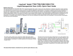
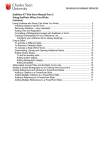
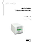
Nanoparticle Nebulizer Model 7788:User Manual Part Number: 2679001 Version 1.0 Nanoparticle Nebulizer Model User Manual Copyright © Fluid Measurement Technologies, Inc. 2014. All rights reserved. Address: Fluid Measurement Technologies, Inc. 4106 Hoffman Road White Bear Lake, MN 55110‐3708 USA Phone Number: 651‐762‐7762 Fax Number: 651‐762‐7763 URL: www.fmtdevelop.com The following is a history of the Nanoparticle Nebulizer Model 7788 User Manual (part number ): Version Date Change Version 1.0 December 2014 All trademarks appearing in this manual are the property of their respective owners Fluid Measurement Technologies, Inc. may have patents or pending patent applications, trademarks, copyrights, or other intellectual property rights covering subject matter in this document. Providing you with this document does not give license to these patents, trademarks, copyrights or the intellectual property except as expressly provided in a written agreement from Fluid Measurement Technologies, Inc. Nanoparticle Nebulizer User Guide i Version 1.0 Limitation of Warranty and Liability Fluid Measurement Technologies (FMT), Inc. offers a full 12‐month repair or replacement warranty on all products sold. Warranty covers defects resulting from design or manufacturing. If any such product proves defective during this warranty period, FMT Inc., at its option, either will repair the defective product without charge for parts and labor, or will provide a replacement in exchange for the defective product. This warranty is offered on a return to factory basis, with return shipping expense expressly at the cost of the customer. FMT Inc. will pay the return shipping on any materials repaired or replaced. Any repaired or replaced item assumes the remainder of the initial warranty period. FMT Inc. warrants only to the extent of replacement or repair of our products, and does not assume any responsibility for consequential damages. No warranty is offered on accounts with past due balances. In order to obtain service under this warranty, Customer must notify FMT Inc., of the defect before the expiration of the warranty period and make suitable arrangements for the performance of service. The Customer shall be responsible for packaging and shipping the defective product to the service center designated by FMT Inc., with shipping charges prepaid. This warranty shall not apply to any defect, failure or damage caused by improper use or improper or inadequate maintenance and care. FMT Inc. shall not be obligated to furnish service under this warranty a) to repair damage resulting from attempts by personnel other than FMT Inc. representatives to install, repair or service the product; b) to repair damage resulting from improper use or connection to incompatible equipment; or c) to service a product that has been modified or integrated with other products when the effect of such modification or integration increases the time or difficulty of servicing the product. THIS WARRANTY IS GIVEN BY FMT INC. WITH RESPECT TO THE LISTED PRODUCTS IN LIEU OF ANY OTHER WARRANTIES, EXPRESS OR IMPLIED. FMT AND ITS VENDORS DISCLAIM ANY IMPLIED WARRANTIES OF MERCHANTABILITY OR FITNESS FOR A PARTICULAR PURPOSE. FMT RESPONSIBILITY TO REPAIR OR REPLACE DEFECTIVE PRODUCTS IS THE SOLE AND EXCLUSIVE REMEDY PROVIDED TO THE CUSTOMER FOR BREACH OF THIS WARRANTY. FMT AND ITS VENDORS WILL NOT BE LIABLE FOR ANY INDIRECT, SPECIAL, INCIDENTAL, OR CONSEQUENTIAL DAMAGES IRRESPECTIVE OF WHETHER FMT LLC OR THE VENDOR HAS ADVANCE NOTICE OF THE POSSIBILITY OF SUCH DAMAGES. Service Policy Knowing that inoperative or defective instruments are a detriment to our customers’ satisfaction, our service policy is to give prompt attention to any known problems. If you discover any malfunction of the NRM 8000, contact FMT Inc. at 651‐762‐7762 (USA). If you are outside of the USA, please call your authorized distributor. Nanoparticle Nebulizer User Guide ii Version 1.0 Table of Contents About This Manual ..................................................................................................................... 1 Intended Audience .................................................................................................................. 1 Scope of User Manual.............................................................................................................. 1 Definitions................................................................................................................................. 1 Safety and Handling Procedures .............................................................................................. 2 Safety Signals ............................................................................................................................ 2 Warnings ................................................................................................................................... 3 How the Nanoparticle Nebulizer Works ................................................................................ 4 Applications.............................................................................................................................. 6 Acknowledgement................................................................................................................... 7 How to Install the Nanoparticle Nebulizer Model 7788 ...................................................... 8 Installation Overview .............................................................................................................. 8 Unpacking the Nanoparticle Nebulizer................................................................................ 8 Equipment You Need .............................................................................................................. 9 Flaring a Tube......................................................................................................................... 10 Installing the Nanoparticle Nebulizer................................................................................. 10 Connecting the Water Drain........................................................................................................... 11 Connecting the Compressed Air or Nitrogen Supply................................................................. 12 Connecting the Power ..................................................................................................................... 13 Connecting the Ultrapure Water Supply ...................................................................................... 14 Connecting the Aerosol Outlet....................................................................................................... 15 Connecting the Direct Injection Inlet............................................................................................. 15 Warming Up the Nebulizer ............................................................................................................ 16 Operation Instructions ............................................................................................................. 17 The Back Panel........................................................................................................................ 17 The Front Panel ...................................................................................................................... 18 Checking the Instrument Status........................................................................................... 19 Changing the Online Sample Pressure.......................................................................................... 20 Changing the Instrument Settings ....................................................................................... 20 Changing the Date and/or Time..................................................................................................... 21 Adjusting the Nebulizer Temperature .......................................................................................... 22 Adjusting the Evaporator Temperature........................................................................................ 23 Setting the Drip Counter Drop Volume........................................................................................ 24 Inspection Volume ........................................................................................................................... 25 Setting the Nebulizer or UPW pressure to Zero .......................................................................... 25 Managing Pump Life ....................................................................................................................... 26 Data Collection and Plotting ................................................................................................ 27 Turning Data Logging On/Off........................................................................................................ 27 Transferring Data to a USB drive................................................................................................... 27 Turning Data Plotting On/Off ........................................................................................................ 28 Managing Internal Memory............................................................................................................ 28 Sample Introduction .............................................................................................................. 30 Online Sample Introduction ........................................................................................................... 30 Direct Injection Sample Introduction ............................................................................................ 32 Nanoparticle Nebulizer User Guide iii Version 1.0 How to Shut Down the Nanoparticle Nebulizer for Moving or Shipping .................... 34 Troubleshooting ........................................................................................................................ 35 Unblocking Orifices ............................................................................................................... 35 Appendix A: Nanoparticle Nebulizer Model 7788 Specifications ................................... 36 Nanoparticle Nebulizer User Guide iv Version 1.0 About This Manual About This Manual Intended Audience The Nanoparticle Nebulizer Model 7788 User Manual is intended to be used by qualified personnel (such as technicians and engineers) in a semiconductor facility or laboratory setting. Scope of User Manual This user manual contains detailed instructions for the installation and set up of the Nanoparticle Nebulizer Model 7788. The manual also contains an explanation of how the nebulizer works. Definitions UPW: Ultrapure Water EU: European Union RAE: Residue After Evaporation CPC: Condensation Particle Counter WCPC: Water‐based Condensation Particle Counter EEPROM: Electrically Erased Programmable Read Only Memory KCl: Potassium Chloride psi: pounds per square inch kPa: Kilo Pascals PFA: Perfluoralkoxy PEEK: Polyether Ether Ketone VAC/VDC: Volts Alternating Current/Volts Direct Current AC: Alternating Current USB: Universal Serial Bus mA: Milliamperes NVR: Non‐Volatile Residue Nanoparticle Nebulizer User Guide 1 Version 1.0 NRM 8000: Safety and Handling Procedures Safety and Handling Procedures Read this section to learn safe handling procedures for the Nanoparticle Nebulizer. There are limited user‐serviceable parts inside the Nanoparticle Nebulizer: all repair and maintenance must be performed by a qualified service technician. When working with the Nanoparticle Nebulizer: Do not remove any parts from the instrument unless this manual tells you to do so. Do not remove the instrument housing or covers while power is supplied to the instrument. Safety Signals The following warning symbols and labels are used in the documentation and on the Nanoparticle Nebulizer. Follow the procedures described in this manual to use the instrument safely. Warning Warnings are used for the following purposes: To indicate that unsafe use of the instrument could result in serious injury to you or cause irrevocable damage to the instrument. To indicate that if you do not follow the procedures described in this manual, you may damage the instrument. To draw attention to important information about the operation and maintenance of the Nanoparticle Nebulizer. High Voltage Sticker A High Voltage warning sticker attached to the Nanoparticle Nebulizer warns you that uninsulated voltage within the instrument may be sufficient to give you an electric shock. Do not make contact with any part inside the instrument. Grounding Connection Sticker A Grounding Connection sticker attached to the Nanoparticle Nebulizer indicates that the nebulizer is connected to earth ground and cabinet ground. Nanoparticle Nebulizer User Guide 2 Version 1.0 NRM 8000: Safety and Handling Procedures Warnings Please familiarize yourself with the following warnings before operating the Nanoparticle Nebulizer: The Nanoparticle Nebulizer must be used following manufacturer’s specifications otherwise safety cannot be guaranteed. All service work must be performed by qualified service technicians ‐ only qualified service technicians should remove the cover. When the nebulizer is running, there are hot surfaces inside the device. Do not remove the cover at any time unless you are a qualified service technician. To prevent electric shocks, ensure that all electrical outlets are grounded. Follow the instructions for all inlet and outlet connections. Incorrect connections will cause the nebulizer to malfunction. The air or nitrogen supplied to the nebulizer must be clean, dried, oil‐free and regulated at 50‐60 psi. During normal operation, do not tilt the nebulizer at angles >10. You must drain the nebulizer before you move or ship it. Do not ship an undried/undrained nebulizer back to Fluid Measurement Technologies, Inc. Doing so may damage the device and invalidate the warranty. Do not subject an undrained nebulizer to freezing temperatures. Doing so will damage the device and invalidate the warranty. Nanoparticle Nebulizer User Guide 3 Version 1.0 Nanoparticle Nebulizer: How It Works How the Nanoparticle Nebulizer Works The Nanoparticle Nebulizer aerosolizes aqueous suspensions of particles with reduced interference from nonvolatile residue present in the sample. The liquid sample is metered into the instrument via a peristaltic pump, combined with a known ratio of ultrapure water, and nebulized into fine droplets. An impaction pin positioned within 1.0 mm of the nebulizer nozzle removes the largest liquid droplets. The remaining wet aerosol has a nominal average droplet size of ~ 200 nm. The aerosol is conditioned at an elevated temperature to evaporate liquid, leaving only the particles and dissolved residue within the sample. The particles are then combined with clean, dry air. Up to 2 L/min of dry aerosol flow can be drawn from the aerosol outlet. Using a traditional nebulizer to create an aerosol of colloidal particles often results in interference from any non volatile residue present in the sample. After droplet evaporation, non volatile residue creates particles of residue regardless of whether the droplets contain colloidal particles or not. When there is a particle in a droplet, non‐volatile residue forms a coating on the particle. This coating is problematic when you aerosolize small particles (<30nm) or particles where the surface properties are of concern (such as toxicology studies). The Nanoparticle Nebulizer mitigates nonvolatile coating by minimizing the size of the nebulized droplet, thereby reducing the influence of non‐volatile residue on the final aerosol properties (shown in Figure 1). Figure 2 is a schematic diagram illustrating the main components of the Nanoparticle Nebulizer. Nanoparticle Nebulizer User Guide 4 Version 1.0 Nanoparticle Nebulizer: How It Works Figure 1: Nanoparticle Nebulizer minimizing non‐volatile residue particle coating (Illustration taken from presentation given by TSI Inc. at Pittcon 2012,) Figure 2: Schematic Diagram of the Nanoparticle Nebulizer Model 7788. Air Inlet Drain Port Nebulizer Gas Pressure Regulator Drain Pump 98 ml/min HEPA Filter P 2 ml/min Drip Counter T Nebulizer Evaporator P Water Requlator Pilot Pressure Online Sample Inlet 100 ml/min Water Back Pressure Valve and Rotameter Nanoparticle Nebulizer User Guide Direct Injection Inlet and Selector Valve Impactor Pin adjustment on RHS Dilution Vent Aerosol Outlet 5 Version 1.0 Nanoparticle Nebulizer: How It Works The Nanoparticle Nebulizer offers the following advantages over existing nebulizer technology: Produces droplets less than 1μm in diameter. Limits the influence of non‐volatile residue on nebulized particles. High sample flow rate. Continuous on‐line flow rate to the nebulizer. Ability to inject a small sample directly into the nebulizer. Does not require a conductive solution (unlike electrospray aerosolization). Integrated heated evaporator. Drip counter to monitor nebulizer sample flow rate. Temperature and pressure logging of on‐line sample flow. Feedback control of evaporator and nebulizer housing temperatures. Applications The Nanoparticle Nebulizer can be used as a stand alone instrument or as part of a Liquid Nanoparticle Sizer (LNS) system. The Nanoparticle Nebulizer can be used as a stand‐alone instrument for the following applications: Analyzing CMP slurries. Characterizing liquid filter media. Analyzing drugs and other medical nanoparticles in water. Analyzing environmental water samples. The Nanoparticle Nebulizer can also be used as part of a Liquid Nanoparticle Sizer (LNS) system. The principle application of the Nanoparticle Nebulizer is to characterize the size‐distribution of particles within a colloid. This is most commonly accomplished using a Scanning Mobility Particle Sizer (SMPS). The configuration of an SMPS and Nanoparticle Nebulizer is defined as a Liquid Nanoparticle Sizer (LNS) and is protected by patents US 8,272,253 and US 8,573,034, The LNS system is available from Fluid Measurement Technologies, Inc. Licensing is available for customers who already own aerosol spectrometer instrumentation. Nanoparticle Nebulizer User Guide 6 Version 1.0 Nanoparticle Nebulizer: How It Works Acknowledgement The ultrafine nebulization method used in this device is based on technology licensed from CT Associates, Inc. (CTA). We offer our sincere thanks to Don Grant, Gary Van Schooneveld, and Mark Litchy for their invention, their clever insights to this unique technology, and the gracious feedback they have provided during the development of this product. Patent numbers 8,272,253 and 8,573,034 have been issued to CTA and licensed by FMT. Patent number 7,852,465 has been issued to FMT. Nanoparticle Nebulizer User Guide 7 Version 1.0 Nanoparticle Nebulizer Model 7788: Installation How to Install the Nanoparticle Nebulizer Model 7788 The Nanoparticle Nebulizer can be installed as a stand‐alone instrument or as part of an LNS system. It can also be operated as an online instrument or using direct injection. Installation Overview Following is an overview of the steps required to get your Nanoparticle Nebulizer up and running. Please read the detailed instructions (beginning below) for each step before you set up the instrument. Unpacking the Nanoparticle Nebulizer. Connecting the waste outlet. Connecting the air supply. Connecting the power. Connecting the water supply. Connecting the aerosol outlet. Unpacking the Nanoparticle Nebulizer To unpack the Nanoparticle Nebulizer, follow these instructions: 1. Carefully remove the nebulizer from its shipping container. Save the original packing materials for use when shipping the nebulizer back to Fluid Measurement Technologies, Inc. for service, or for moving the nebulizer to a different location. Warning. If the Nanoparticle Nebulizer is returned to FMT, Inc. in anything other than the original shipping container, you will be charged for any damage that occurs during shipping. If you do not have the original shipping container, contact FMT, Inc. at 651‐762‐7762. 2. Place the nebulizer on a level surface. 3. Make sure there is an unrestricted air flow around the device. Fluid Measurement Technologies, Inc. recommends at least a 2‐inch air gap on both sides and the top of the instrument. 4. Allow the nebulizer to reach ambient temperature, if necessary. 5. Make sure all the items listed in Table 1, were included in the Nanoparticle Nebulizer shipment. If any of the items are missing, or damaged, please call Fluid Measurement Technologies, Inc. at 651‐762‐ 7762. Nanoparticle Nebulizer User Guide 8 Version 1.0 Nanoparticle Nebulizer Model 7788: Installation Table 1: Nanoparticle Nebulizer Model 7788 Part Number Model 7788 1977788 2679105 1330001 1022495 Description Nanoparticle Nebulizer User Manual, Printed USB Flash Drive containing the Nebulizer User Manual Power Supply Cable (USA only) CDA/N2 Adapter Fitting Quantity 1 1 1 1 1 Equipment You Need To install the Nanoparticle Nebulizer, you will require the following items: 9/16 wrench. A length of ¼ inch OD tubing sufficient to reach from the instrument to your waste drain (12 ft maximum length). A length of ¼ inch OD polyethylene tubing sufficient to reach from the instrument to your air supply. For online sample introduction: o A length of ¼ inch OD PFA tubing sufficient to reach from the instrument to your water supply. o PFA tubing flaring tool, tube gripper, and heat gun. o Ultrapure Water supply. Note: Water pressure should be 20‐70 psi. For direct sample injection: o A sample delivery pump (such as peristaltic or syringe) or a pressurized vessel. o A sufficient length of 1/16 inch OD HPLC/UPW‐grade tubing. o A standard 10‐32x1/16 inch OD HPLC compression fitting. Conductive tubing for transporting the generated aerosol. A supply of clean, dry, compressed air. Note: The air pressure should be 50‐60 psi. Access to a suitable liquid waste outlet. 120‐240 VAC power at 50/60 Hz. Note: No tubing is supplied with the Nanoparticle Nebulizer. Nanoparticle Nebulizer User Guide 9 Version 1.0 Nanoparticle Nebulizer Model 7788: Installation Flaring a Tube The installation procedure for online analysis requires you to flare a PFA tube. You can either use a heat flaring tool provided by Entegris (customer service numbers: 952‐556‐4196 or 800‐394‐4083) or a cold flaring tool provided by Saint Gobain Performance Plastics (customer service numbers: 714‐630‐5818 or 800‐833‐5661). The following instructions describe the hot‐ flare method: 1. Hold a length of PFA tubing with a tube gripper. 2. Rotate one end of the tubing evenly over the heat gun. 3. As soon as the end of the tubing becomes clear, push it onto a flaring tool in your required size. Note: If you remove the tubing from the flaring tool too soon, the end shrinks. If you overheat the tube, the tubing will buckle. 4. Hold in place until the tubing is cool (at least two minutes). 5. Pull the tubing from the flare. It is now ready to attach to a fitting. Installing the Nanoparticle Nebulizer Figures 3 and 4 show the front and back panels of the Nanoparticle Nebulizer. Figure 3: Front Panel of the Nanoparticle Nebulizer. Aerosol Out Display Screen Total Flow Flowmeter Online Sample Pressure Regulator Sample Selector Valve Direct Injection Inlet Online Sample Inlet Nanoparticle Nebulizer User Guide 10 Version 1.0 Nanoparticle Nebulizer Model 7788: Installation Figure 4: Back Panel of the Nanoparticle Nebulizer. USB Port Cooling Fan DB9 Port (not used) Nebulizer Pressure Air Inlet Ethernet Port (not used) Nebulizer Drain Power Connector Waste Outlet Connecting the Water Drain Excess sample from the nebulization module is removed from the instrument using a solenoid pump. For online sampling, the excess total flow that is not delivered to the nebulization module is combined inside the device downstream of the pump. Follow these instructions to connect the water drain: 1. Remove the protective cap from the WASTE OUTLET on the back panel. Nanoparticle Nebulizer User Guide 11 Version 1.0 Nanoparticle Nebulizer Model 7788: Installation 2. Using a 6 ft length of ¼ inch OD polyethylene tubing with a Swagelok fitting on one end, insert the tubing into the WASTE OUTLET fitting on the back panel. Front Ferrule Backing Ferrule Swagelok Nut 3. Using an adjustable wrench, tighten the Swagelok nut one turn past hand‐tight to swage the ferrules onto the tubing. Once the ferrules have been swaged the fitting only requires slight tightening upon reassembly. Warning: Do not over‐tighten the fitting or you will damage the tube and/or fitting. 4. Place the other end of the tube over your drain. Connecting the Compressed Air or Nitrogen Supply The air or nitrogen supplied to the Nanoparticle Nebulizer must be clean, dried, oil‐free and regulated at 345‐414 kPa (50‐60 psi). Follow these instructions to connect the compressed air supply: 1. Remove the protective cap from the AIR INLET on the back panel. Nanoparticle Nebulizer User Guide 12 Version 1.0 Nanoparticle Nebulizer Model 7788: Installation 2. Using a length of ¼ inch OD polyethylene tubing with a Swagelok fitting on one end, insert the tubing into the AIR INLET fitting on the back panel. Air Inlet 3. Using an adjustable wrench, tighten the Swagelok nut one‐half turn past hand tight to swage the ferrules onto the tubing. Once the ferrules have been swaged, the fitting only requires slight tightening upon reassembly. 4. Connect the other end of the tube to your air supply. 5. Turn on the air at the source. The incoming pressure must be regulated at 345‐414 kPa (50‐60 psi). Connecting the Power To connect the power supply, follow these instructions: 1. Plug the supplied power cable into the AC plug receptacle on the back panel of the nebulizer. Plug Receptacle 2. Plug the cord into an earth‐grounded AC power source (100 to 240 VAC, 50 to 60 Hz, 0.6 A). WARNING: Ensure that the ground is secure. Connection to an improperly grounded electrical source is a severe shock hazard. Nanoparticle Nebulizer User Guide 13 Version 1.0 Nanoparticle Nebulizer Model 7788: Installation Connecting the Ultrapure Water Supply Water must be supplied to the nebulizer through a ¼‐inch diameter Teflon PFA tube specially adapted to fit the WATER INLET fitting on the front panel of the nebulizer. To prepare the PFA tube for attachment to the WATER INLET fitting, take the following precautions: Make sure your hands are clean. Do not touch the end of the water supply tube ‐ you may contaminate it. To connect the ultrapure water supply, follow these instructions: 1. Cut the end of the PFA tubing evenly with a clean tube cutter. 2. Place a Flaretek nut over the end of the PFA tube before attempting to flare the end. 3. Flare the tube (see instructions on page 10). 4. Flush ultrapure water through the tube for several minutes to remove any debris created by the flaring process. 5. Remove the protective nut and plug from the ONLINE SAMPLE INLET fitting. Keep this Flaretek nut and plug for use when moving or shipping the nebulizer. (See shutdown instructions on page 34). 6. Push the flared end of the tube onto the ONLINE SAMPLE INLET. Flared PFA Tubing 7. Slide the Flaretek nut into place and hand‐tighten. Nanoparticle Nebulizer User Guide 14 Version 1.0 Nanoparticle Nebulizer Model 7788: Installation Flaretek Nut 8. Turn on the ultrapure water supply. Water then flows through the instrument and out through the waste line. Ensure the ONLINE SAMPLE INLET has no leaks. If you see any leaks, tighten the fitting. Connecting the Aerosol Outlet To connect the aerosol waste line, follow these instructions: 1. Remove the protective cap from the AEROSOL OUT fitting. 2. Using the shortest practical length of ¼ in black conductive tubing, push one end of the tubing onto the AEROSOL OUT fitting. Note: The aerosol outlet is at near‐atmospheric pressure with an internal vent. If the measurement device draws more than 2.5 L/min, ambient aerosol will be drawn into the sample stream. The device must draw more than 1 L/min to prevent condensation from forming in the aerosol lines. Connecting the Direct Injection Inlet To connect the Direct Injection inlet, follow these instructions: 1. Turn the Sample Selector Valve to DIRECT. Sample Selector Valve 2. Remove the protective cap from the DIRECT INJECTION fitting. Nanoparticle Nebulizer User Guide 15 Version 1.0 Nanoparticle Nebulizer Model 7788: Installation 3. Take a sufficient length of 1/16 in tubing with a standard 10‐32 chromatography fitting on one end and insert the fitting into the DIRECT INJECTION INLET. 4. Tighten the nut to finger tight. Direct Injection Inlet Warming Up the Nebulizer Using the rocker switch on the back panel, turn the power on. You see the instrument splash screen and the nebulizer automatically begins its warm‐up procedure. The warm‐up procedure may take up to 15 minutes. If you experience any problems installing your Nanoparticle Nebulizer, please contact Fluid Measurement Technologies, Inc. at 651‐762‐7762. Nanoparticle Nebulizer User Guide 16 Version 1.0 Nanoparticle Nebulizer: Operation Operation Instructions Once all installation procedures have been completed, you are ready to begin standard operation of the Nanoparticle Nebulizer. The Back Panel Components of the Nanoparticle Nebulizer back panel include the following: Nebulizer Pressure Regulator. Nebulizer Drain, Waste Outlet, and Air Inlet. The Data Communication ports. Figure 7: Nanoparticle Nebulizer Back Panel. USB Port Cooling Fan DB9 Port (not used) Nebulizer Pressure Air Inlet Nebulizer Drain Ethernet Port (not used) Waste Outlet Power Connector Nanoparticle Nebulizer User Guide 17 Version 1.0 Nanoparticle Nebulizer: Operation The Front Panel Components of the Nanoparticle Nebulizer front panel include the following: Aerosol Out, Sample Inlet, and Direct Injection Inlet. Sample Selector Valve. Online Sample Pressure regulator and Total Flow Flowmeter. Touch‐screen Display. Figure 8: Nanoparticle Nebulizer Front Panel. Display Screen Aerosol Out Total Flow Flowmeter Online Sample Pressure Regulator Sample Selector Valve Direct Injection Inlet Online Sample Inlet The Nanoparticle Nebulizer is operated using the touch‐screen display and the F1, F2, F3, and F4 buttons. The F buttons perform the following functions: F1: Press F1 to view instrument status. F2: Press F2 to view/change instrument settings. F3: Press F3 to view/change data collection options. F4: Press F4 to view/change onscreen charts. Note: The System button is non‐functional. Nanoparticle Nebulizer User Guide 18 Version 1.0 Nanoparticle Nebulizer: Operation Checking the Instrument Status Press F1 to see the Device Status screen. The current time and date (hh:mm:ss, dd‐mm‐yyyy) is displayed at the upper center of the screen. Any status readings displayed in red indicate that the status is outside the acceptable range. Figure 9: Nanoparticle Nebulizer Device Status Screen. The Device Status screen displays the following instrument statuses: Sample Pressure: Online Sample Pressure in psi. The nominal value is 18 psi. Sample Temperature: Displays the sample temperature in °C. Nebulizer Gas Pressure: Displays the nebulizer gas pressure in psi. The nominal value is 35 psi. Adjust the nebulizer gas pressure using the Nebulizer Pressure regulator on the back panel. Nebulizer Temperature: Displays the nebulizer temperature in °C. The nominal value is 19 °C, but may need adjustment based on the ambient temperature and the sample temperature. Adjust to a point where the temperature is stable. Note: The nebulizer temperature should nominally be set to 5°C lower than the UPW temperature. Evaporator Temperature: Displays the evaporator temperature in °C. The nominal value is 60°C If the display is red, the temperature has not reached the set point. Sample Nebulizer Flow: Displays the flow to the nebulization module in ml/min. Nanoparticle Nebulizer User Guide 19 Version 1.0 Nanoparticle Nebulizer: Operation Changing the Online Sample Pressure To adjust the Online Sample Flow pressure, follow these instructions: 1. Press F1 to view the status screen. 2. Turn the Online Sample Pressure regulator on the front panel until the Online Sample Pressure reads 18.0 psi. Note: Adjusting the online sample pressure also affects the total sample flow. You may need to make iterative adjustments. Changing the Instrument Settings Press F2 to see the Device Settings screen. Figure 10: Nanoparticle Nebulizer Device Settings Screen The Device Settings screen displays the following: Nebulizer Temperature: allows you to set the nebulizer temperature. Evaporator Temperature: allows you to set the evaporator temperature. Calibration: allows you to set the time, drip counter drop volume, and inspection volume. Drain Pump button: allows you to turn the pump on and off to lengthen its life. Nanoparticle Nebulizer User Guide 20 Version 1.0 Nanoparticle Nebulizer: Operation Changing the Date and/or Time To change the date and time, follow these instructions: 1. Press F2. 2. On the Device Settings screen, touch Calibration. 3. On the Calibration Settings screen, touch Sec to change the seconds, Min to change the minutes, Hours to change the hours, Day to change the day, Month to change the month, and Year to change the year. Use the on‐screen keypad to enter a value for any of the parameters you wish to change, then touch Enter. Nanoparticle Nebulizer User Guide 21 Version 1.0 Nanoparticle Nebulizer: Operation Note: buttons index the temperature. buttons set the cursor. ± sets the sign on the number. 4. Press Set Time. The date and time appear at the upper center of the Status screen. Adjusting the Nebulizer Temperature The Nebulizer Temperature should nominally be set 5 °C lower than the UPW temperature. If the Nebulizer Temperature status indicator is red, the temperature is not within 2 °C of the temperature set point (as seen on the Status screen). To adjust the Nebulizer temperature, follow these instructions: 1. Press F2. 2. On the Device Settings screen, touch Nebulizer Temperature. 3. On the resulting on‐screen keyboard, touch the numbers to enter the required temperature, then touch Enter. The updated set point appears on the Device Settings screen. Note: buttons index the temperature. buttons set the cursor. ± sets the sign on the number. Nanoparticle Nebulizer User Guide 22 Version 1.0 Nanoparticle Nebulizer: Operation Adjusting the Evaporator Temperature If the Evaporator Temperature status indicator is red, the temperature is not ±2 °C of the temperature set point (as seen on the Settings screen). To adjust the evaporator temperature, follow these instructions. 1. Press F2. 2. On the Device Settings screen, touch Evaporator Temperature. 3. On the resulting on‐screen keyboard, touch the numbers to enter the required temperature, then touch Enter. Note: buttons index the temperature. buttons set the cursor. ± sets the sign on the number. The updated set point appears on the Device Settings screen. Nanoparticle Nebulizer User Guide 23 Version 1.0 Nanoparticle Nebulizer: Operation Setting the Drip Counter Drop Volume The Drip Counter Drop Volume is set at the factory and is used to calibrate the drip flow meter used to indicate the flow rate to the nebulizer module. If necessary, the Drip Counter Drop Volume can be calibrated using the direct injection method. To calibrate the drip counter drop volume, follow these instructions: 1. Turn the sample switch to Direct. 2. Inject a set volume flow rate using a suitable pump at 2 ml/min of UPW into the Direct Injection Inlet. 3. Press F2. On the Device Settings screen, touch Calibration. Nanoparticle Nebulizer User Guide 24 Version 1.0 Nanoparticle Nebulizer: Operation 4. On the Calibration Settings screen, touch Drip Counter Drop Volume. 5. After 2 minutes, view the nebulizer flow rate on the status screen. Proportionately adjust the drop volume on the calibration menu to achieve the proper displayed flow rate. Inspection Volume The inspection volume is factory set and requires a Liquid Nanoparticle Sizer System (with a known volume standard provided by FMT ) to calibrate. Setting the Nebulizer or UPW pressure to Zero If the air and water supplies to the instrument are turned off, the Nebulizer and UPW pressure on the Device Status screen should be 0. To reset the Neb Zero or UPW Zero, follow these instructions: 1. With the air and water supplies turned off, press F2. 2. On the Device Settings screen, touch Calibration. Nanoparticle Nebulizer User Guide 25 Version 1.0 Nanoparticle Nebulizer: Operation 3. On the Calibration Settings screen, touch Neb Zero P or UPW Zero P. The zeros are reset. Managing Pump Life The Nanoparticle Nebulizer contains a solenoid‐type liquid pump to remove sample that has been nebulized but removed from the aerosol before evaporation (only 0.1% of the nebulized sample is aerosolized and measured by the device). The pump has a finite life which can be extended by turning off the pump when no liquid is being delivered to the system. To turn the drain pump on/off, follow these instructions: 1. Press F3. 2. The Drain Pump button is a toggle. Touch the button to turn the pump on or off. Nanoparticle Nebulizer User Guide 26 Version 1.0 Nanoparticle Nebulizer: Operation Data Collection and Plotting When the data logging function is turned on, the Nanoparticle Nebulizer stores status data in its internal memory. You can transfer the stored data to an external Flash memory drive. The sample pressure, temperature, and drip rate data can be viewed as either a 2‐hour or 12‐hour trend plot. To see the trend plot, press F4. Turning Data Logging On/Off To turn data logging on/off, follow these instructions: 3. Press F3. 4. The Data Logging button is a toggle. Touch the button to turn data logging On or Off. Transferring Data to a USB drive To transfer data to an external USB drive, follow these instructions: 1. Insert a USB drive into the back panel. Note: The photographs show the FMT‐supplied drive (containing the User Manual). 2. Press F3. Nanoparticle Nebulizer User Guide 27 Version 1.0 Nanoparticle Nebulizer: Operation 3. Press Save Data to External USB Drive. When data transfer begins, the button turns green and briefly says Transferring. 4. When the button no longer says Transferring, remove the USB drive. Turning Data Plotting On/Off To turn data plotting on or off, follow these instructions: 1. Press F3. 2. The Plotting button is a toggle. Press Plotting to turn data plotting On or Off. Managing Internal Memory To manage the internal memory you can view the data record files, check the available memory and the total memory used, format the drive, and delete the stored data. To view the data record and the available memory, follow these instructions: 1. Press F3. 2. On the Manage Internal screen, touch Manage Internal Memory. Nanoparticle Nebulizer User Guide 28 Version 1.0 Nanoparticle Nebulizer: Operation Free: indicates the amount of memory available in kB. Total: indicates the memory usage. 3. Using the scroll bar arrows to move the highlighting bar, select the record you wish to view, then press (Enter). Note: The data files for each day that data was collected are displayed in comma delimited records. To delete data from the internal memory, follow these instructions: 1. Press F3. 2. Press Manage Internal Memory. 3. Using the scroll bar arrows to move the highlighting bar, select the data record or folder you wish to delete. Note: To enter a sub directory, highlight the folder and press the (Enter) key. 4. Touch Del to delete the selected record. To delete all the files in a folder, touch Del All. Nanoparticle Nebulizer User Guide 29 Version 1.0 Nanoparticle Nebulizer: Operation Sample Introduction The Nanoparticle Nebulizer has two options for introducing the sample to be nebulized: online and direct. Online Sample Introduction Raw online sample introduction is useful for monitoring particle concentrations in high purity water streams. The ouput aerosol can be measured directly with a particle counter although this configuration is not ideal due to potential influence by particles formed from previously dissolved non‐volatile residue. For these applications, the Model 1000 Scanning Threshold Particle Counter (available from Fluid Measurement Technologies, Inc.) is a more suitable instrument. A more typical configuration of the online sample inlet configuration is to employ an inline, sample introduction module (FMT Model 7780). The principle benefit of the Model 7780 is the ability to reduce the amount of Non‐volatile Residue (NVR) present in the nebulized stream when diluted with ultrapure water. The online process eliminates the possibility of NVR introduction from vials, sample measurement/transfer, and exposure to air. The Model 7780 allows for online sample dilution between 100X and 10000X. Direct connection of the 7780 to the 7788 is used for analysis of colloid properties or for aerosol generation/dispersion of the colloid particles. A liquid filter may be placed between the 7780 and 7788 for filter load testing. Figures 11 and 12 show the configuration of a Model 7780 connected to the Nanoparticle Nebulizer and a schematic diagram of the Model 7780. Nanoparticle Nebulizer User Guide 30 Version 1.0 Nanoparticle Nebulizer: Operation Figure 11: Nanoparticle Nebulizer Connected to Model 7780. Nanoparticle Nebulizer Model 7780 Nanoparticle Nebulizer User Guide 31 Version 1.0 Nanoparticle Nebulizer: Operation Figure 12: Schematic Diagram of the Model 7780. UPW Inlet Turbulent Mixers Sample Inlet Diluted Sample Out Direct Injection Sample Introduction Direct injection of a sample into the Model 7788 can be accomplished by a peristaltic pump, syringe drive pump, or pressurized vessel. The peristaltic pump adds the most particles and the pressurized vessel the least. The injection rates for both pumps should match the average flow rate measured Nanoparticle Nebulizer User Guide 32 Version 1.0 Nanoparticle Nebulizer: Operation by the 7788 under normal operating conditions. For pressurized vessel introduction, the vessel pressure should match the normal online sample pressure (18 psi). Figure 13 shows a pressure vessel configuration. Note: The vessel must withstand the total pressure which can be supplied by the compressed air system. Use of a blow‐off safety valve is highly recommended. Figure 13: Pressure Vessel Configuration with the Nanoparticle Nebulizer. Pressurized Gas at 18 PSI To Nebulizer Nanoparticle Nebulizer User Guide 33 Version 1.0 Nanoparticle Nebulizer: Moving and Shipping How to Shut Down the Nanoparticle Nebulizer for Moving or Shipping If you need to move the Nanoparticle Nebulizer to another lab or facility, or if you need to ship it for service, read this section to familiarize yourself with the precautions you should take and the procedures you should follow. Performing any of the following improper handling techniques may damage the instrument and will invalidate the warranty: Shipping/transporting an undried/undrained instrument. Tipping > 10 during normal operation. Subjecting an undried/undrained instrument to freezing temperatures. To prepare the Nanoparticle Nebulizer for shipping, follow these instructions: 1. Turn off the water supply to the nebulizer and wait a few seconds for the water pressure to drop to zero (confirm that the pressure is zero by looking at the Status screen). 2. Keep the power turned on and the compressed air flowing into the AIR INLET on the back panel. 3. Remove the UPW fitting from the back panel as well as the plug for the direct injection port. Note: Water will temporarily drain from the bulkhead fittings 4. Connect the CDA/N2 Adapter Fitting to the ONLINE SAMPLE INLET. Apply 20 psi of air pressure to the adapter. After 30 seconds, replace the direct injection plug. Run the air for 15 minutes. 5. Disconnect the air or nitrogen supply line and the water waste line and turn off the power. 6. Remove the nebulizer drain cap on the back panel .Tilt the device towards the back to allow the nebulizer module reservoir to drain. 7. Place all the caps that you received with the instrument on the inlets and outlets to prevent material from entering the instrument. The Nanoparticle Nebulizer is now prepared for shipping or moving. Note: If you did not save the original protective caps, find suitable alternatives. 8. Place the instrument in its original packing materials for shipping. If you have any questions about shipping or moving the Nanoparticle Nebulizer, contact Fluid Measurement Technologies, Inc. at 651‐762‐7762. Nanoparticle Nebulizer User Guide 34 Version 1.0 NRM 8000: Troubleshooting Troubleshooting All repair and maintenance of the Nanoparticle Nebulizer must be performed by a qualified service technician. When working with the nebulizer: Do not remove any parts from the instrument unless this manual tells you to do so. Do not remove the instrument housing or covers while power is supplied to the instrument. Unblocking Orifices Occasionally orifices or tubes within the Nanoparticle Nebulizer become blocked which may be indicated by a low Nebulizer flow rate. If you suspect a blockage, follow these instructions: 1. Turn the Sample Selector Valve knob on the front panel to Online. 2. Remove the water inlet tubing and run compressed air through the instrument. 3. If the problem is not resolved, turn the Sample Switch to Direct Injection and remove the direct injection plug to force air back through the nebulizer supply tubing. If the nebulizer flowrate does not recover, it is possible that the internal orifices are clogged and the device must be returned to FMT for service. Note: Advanced users may wish to adjust the internal impactor pin, although this step may damage the instrument. Contact FMT for evaluation and instructions. Nanoparticle Nebulizer User Guide 35 Version 1.0 Appendix A: Nanoparticle Nebulizer Model 7788 Specifications Nanoparticle Nebulizer Specifications Peak droplet diameter Droplet dN/dLogDp > 10μm Inspection volume rate Total Liquid Flow Rate (online) Nebulizer Flow Rate (direct) Aerosol Flow Rate Response time to concentration change Inlet Water Pressure (online) Compressed air flow rate/pressure < 1.0 micrometer (nominally 0.3 micrometer) < Peak dN/dLogDp x 10‐5 0.2‐1.0 μL/min 50‐280 mL/min 0.5‐3.0 mL/min 1.0 – 2.5 L/min < 90 seconds 200‐500 kPa (29 – 72 psig) 3 std L/min CDA or Nitrogen, (345‐414 kPa, 50‐60 psi) Wetted Surface Materials PFA Teflon, PTFE, sapphire, 316L, stainless steel, PEEK Ambient Temperature Range 15‐35°C, 59‐95°F Ambient Relative Humidity Range 0‐85% Maximum Water Temperature 80°C, 176°F Dimensions (WxDxH) 23 (9) x 23 (9) x 35.5 (14) (46 (18) with fittings) Weight 6 kg (13..2 lb) Power Universal 100 ‐ 230 VAC 50/60 Hz, 90 W max Output RJ‐45 for Modbus, USB FlashDrive Internal storage Micro SD Ultrapure Water Inlet ¼ inch PFA Flaretek® Waste Outlet ½ inch SS Swagelok® Compressed Air inlet ¼ inch SS Swagelok® Detector vacuum ¼ inch SS Swagelok® port Display 3.5 inch TFT Color, touch panel ® Flaretek is a registered trademark of Entegris, Inc. Swagelok® is a registered trademark of Swagelok Company. Teflon® is a registered trademark of E.I. DuPont de Nemours and Company, Inc. Windows® is a registered trademark of Microsoft Corporation. Specifications subject to change without notice. Nanoparticle Nebulizer User Guide 36 Version 1.0