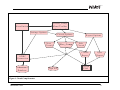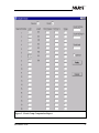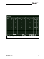
1
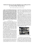
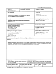
DEVELOPMENT OF MICROSTATION TOOLS
TO COMPUTE CIRCUIT REQUIREMENTS
AND LIGHTING DESIGN ELEMENTS
FINAL REPORT
NOVEMBER 1999
Report Budget Number FMK 759
ITD Contract FC#97-50
NIATT Report #99-06
Prepared for
IDAHO TRANSPORTATION DEPARTMENT
Prepared by
NATIONAL INSTITUTE FOR ADVANCED TRANSPORTATION TECHNOLOGY
UNIVERSITY OF IDAHO
Barry Klas, Software Engineer
Michael Kyte, Principal Investigator
Melissa Lines, Technical Writer
TABLE OF CONTENTS
EXECUTIVE SUMMARY........................................................................................................................ 1
INTRODUCTION & BACKGROUND ............................................................................................................ 1
OVERVIEW OF PROJECTS ...................................................................................................................... 1
STATUS OF PROJECTS .......................................................................................................................... 2
1. Circuit Software (called Circuit Comp)....................................................................................... 2
2. Feasibility Report for Light Fixture Placement Software............................................................ 2
Recommendations ......................................................................................................................... 2
INTRODUCTION .................................................................................................................................... 3
BACKGROUND ..................................................................................................................................... 3
OVERVIEW OF PROJECTS.................................................................................................................. 4
RESEARCH PROJECT ONE: CIRCUIT SOFTWARE ..................................................................................... 4
RESEARCH PROJECT TWO: FEASIBILITY OF DEVELOPING LIGHT FIXTURE PLACEMENT SOFTWARE ........... 4
STATUS OF PROJECTS....................................................................................................................... 5
RESEARCH PROJECT ONE: CIRCUIT SOFTWARE ..................................................................... 5
WORK TASKS NIATT HAS COMPLETED: ................................................................................................ 5
Work Task 1 - Software Requirements Specification (SRS) ......................................................... 5
Work Task 2 - Software Design Description (SDD)....................................................................... 5
How Circuit Comp Will Work.......................................................................................................... 6
Work Task 3 - Software Prototype................................................................................................. 6
How Wire Comp Works.................................................................................................................. 6
WHERE WE STAND NOW ...................................................................................................................... 7
THE NEXT STEP ................................................................................................................................... 7
RESEARCH PROJECT TWO: FEASIBILITY REPORT FOR LIGHT FIXTURE PLACEMENT
SOFTWARE..................................................................................................................................... 11
OVERVIEW OF RESEARCH PROBLEM .................................................................................................... 11
WHAT WE ENVISION ........................................................................................................................... 11
BACKGROUND .................................................................................................................................... 12
RECOMMENDATIONS ........................................................................................................................... 13
MicroStation Tools
i
CALCULATING LUMINANCE AND ILLUMINANCE ....................................................................................... 15
A SEPARATE TOOL VS INTEGRATED WITH CIRCUIT COMP ..................................................................... 15
THE NEXT STEP ................................................................................................................................. 16
APPENDIX A - CIRCUIT COMP SOFTWARE REQUIREMENTS SPECIFICATION ........................ 17
APPENDIX B – CIRCUIT COMP SOFTWARE DESIGN DESCRIPTION........................................... 46
APPENDIX C – CIRCUIT COMP USER’S MANUAL ........................................................................ 137
MicroStation Tools
ii
EXECUTIVE SUMMARY
Introduction & Background
The Idaho Transportation Department (ITD) is interested in developing two new software
tools to improve the efficiency of the highway lighting and signalization design process.
ITD currently performs road lighting/signalization design with the MicroStation CADD
design program, plus two specialized software tools. These tools each have disadvantages:
•
The GTE Aladdin software suggests a pattern of light fixture placement so the designer
can decide where lights should be located. However, the program uses data from an
idealized straight road. As a result, the designer has to adjust the pattern to the road
characteristics of the current design, adding additional time to the design process.
•
The proprietary ITD software calculates minimum wire gauges for the designer.
This program creates no output file, and it sometimes generates illogical results.
•
In addition, both packages are DOS-based. They cannot be used from within
MicroStation, adding even more time to the design process. And, on some Windows
NT or Unix environments, they cannot be used at all.
Overview of Projects
The University of Idaho’s National Institute for Advanced Transportation Technology
(NIATT) contracted with ITD to conduct two research projects:
1. NIATT is developing a software tool that runs within MicroStation and provides lighting
circuitry graphics and also calculates the minimum wire gauges for various electrical
circuits in illumination and signalization
2. NIATT has researched the feasibility of developing a software tool that provides
complete computer aided road lighting design, also within MicroStation.
MicroStation Tools
1
Status of Projects
1. Circuit Software (called Circuit Comp)
NIATT has completed the Software Requirements Specification (SRS), the Software
Design Description (SDD), and a prototype of Circuit Comp’s circuit calculation
algorithm, which is called Wire Comp. Wire Comp is the “guts” of the Circuit Comp
program, where all the circuit calculations take place. It is currently being tested by ITD,
to confirm that its wire gauge and voltage calculations are correct. Once ITD verifies
Wire Comp’s calculations, NIATT will integrate Wire Comp into Circuit Comp, and
finish development of the Circuit Comp product.
2. Feasibility Report for Light Fixture Placement Software
NIATT has researched the feasibility of developing a software tool that would provide
computer aided road lighting design within MicroStation. The powerful new tool we
envision would perform all calculations, determine where to place the light units on the
design plan, and automatically place the light units on the plan for the designer to review.
It would use actual highway designs to generate a pattern for light fixture placement
instead of an idealized straight road.
Recommendations
Developing such powerful software will be a complex task, so we suggest tackling the
project in three stages:
•
First, write a program that would calculate the illumination of a given light
configuration, so the designer could determine the correct locations for the lights, and
place them on the plan manually.
•
Then, consider expanding the program to include pre-existing roadway templates
with pre-set light placement patterns.
•
Finally, the program could be further developed to perform all calculations and
automatically place light units on the design plan.
MicroStation Tools
2
DEVELOPMENT OF MICROSTATION TOOLS TO COMPUTE
CIRCUIT REQUIREMENTS AND LIGHTING DESIGN ELEMENTS
INTRODUCTION
The Idaho Transportation Department (ITD) is interested in developing two new software
tools to improve the efficiency of the highway lighting and signalization design process.
BACKGROUND
ITD currently performs road lighting design with the MicroStation CADD design program,
plus two specialized software tools:
•
The GE Aladdin software generates an idealized pattern of light fixture placement, based
on a mixture of roadway and light fixture characteristics. The lighting designer then uses
the data to decide where lights should be located in the design.
•
A proprietary ITD software tool takes data from the lighting circuit design and calculates
minimum wire gauges, given an acceptable voltage drop. The designer then completes
and documents the design.
These tools have several disadvantages:
•
With the GE Aladdin software, the program uses an idealized straight road to determine a
light fixture placement pattern. The designer must then try to fit this idealized pattern of
light placement to an actual roadway, which is often time intensive.
•
The ITD software that calculates wire gauges is inflexible. It creates no output file or
other opportunity to review the results of previous data. It can also generate illogical
results when calculating multi-branch circuits.
•
Both software packages are DOS-based and the designer cannot use them from within
MicroStation. Switching between programs adds time to the design process.
•
Additionally, on some networks, designers working in a Windows NT or UNIX
environment cannot use these packages at all.
MicroStation Tools
3
OVERVIEW OF PROJECTS
The University of Idaho’s National Institute for Advanced Transportation Technology
(NIATT) contracted with ITD to conduct two research projects:
Research Project One: Circuit Software
NIATT is developing a software tool that provides lighting circuitry graphics and also
calculates the minimum wire gauges for various electrical circuits in illumination and
signalization. The tool will identify each element in the lighting design, save it to a database,
and create a circuit schedule and material quantity plan sheets. All of this information will be
available to the designer in real-time and within MicroStation. This tool, written with MDL,
will also be portable to MicroStation platforms running on DOS, NT, and UNIX.
Research Project Two: Feasibility of Developing Light Fixture
Placement Software
NIATT has researched the feasibility of developing a software tool that provides computer
aided road lighting design. It would perform all calculations, determine where to place the
light units on the design plan, and automatically place the light units on the plan for the
designer to review. It would use actual highway designs to generate a pattern for light fixture
placement instead of an idealized straight road. In addition, the tool would be available
within MicroStation, which would greatly speed up the entire design process. The tool could
be separate from the circuit tool, Circuit Comp, or both tools could be merged into one
lighting software package.
MicroStation Tools
4
STATUS OF PROJECTS
RESEARCH PROJECT ONE: CIRCUIT SOFTWARE
The circuit software tool NIATT is developing is called Circuit Comp. Circuit Comp will
assist the lighting designer in three ways. It will:
•
calculate wire gauges for designated circuits
•
store circuit specifications in an Access database and automatically place the
text on the plan sheet
•
produce onscreen reports of computations as well as a project circuit schedule.
These functions will all be performed within the MicroStation environment, eliminating the
need for any external programs.
Work Tasks NIATT Has Completed:
Work Task 1 - Software Requirements Specification (SRS)
This document specifies the operating environment for this new tool, and exactly what it will
be required to do. The SRS includes hardware requirements, operating systems requirements,
additional software (database, MicroStation, InRoads) requirements, input data types and
structures, output requirements, documentation requirements, computational details, and a
list of features. (See Appendix A).
Work Task 2 - Software Design Description (SDD)
This document defines how the software will work. The SDD incorporates ITD’s software
requirements and describes in detail the software NIATT will be writing, in terms of its
structure, data, and algorithms. (See Appendix B).
MicroStation Tools
5
How Circuit Comp Will Work
•
See Figure 1, p. 8 for a diagram of Circuit Comp’s structure.
•
Within MicroStation, the designer picks the lighting components and places them
on the plan sheet.
•
Circuit Comp will read the design file, and check that all items in the plan are included in
the Access database. If any items are missing, such as circuit type or service information,
Circuit Comp will prompt the designer to enter the missing information.
•
Using data from the design file, Circuit Comp computes wire gauges and voltages
for the circuits.
•
The computations will appear onscreen for the designer's review (See Figure 2, p. 9).
•
Once the designer approves the computations, Circuit Comp will then place the results
directly on the design plan, and generate a project circuit schedule (See Figure 3, p. 10).
Work Task 3 - Software Prototype
In May 1998, NIATT completed Circuit Comp's wire calculation algorithm, called Wire
Comp. Wire Comp is the "guts" of the Circuit Comp program, where all the circuit
calculations take place. It is currently being tested by ITD.
How Wire Comp Works
Wire Comp uses the information the designer has entered into Circuit Comp, such as length
of each segment in each circuit, allowable voltage drop for each circuit, number of segments
in each circuit, type of circuit, etc. It computes the most feasible wire gauge for each
segment, the voltage drop across each segment, and the total voltage drop for each circuit.
The results are then returned to Circuit Comp, for onscreen display.
MicroStation Tools
6
Where We Stand Now
The following has been delivered to ITD:
1. Software Requirements Specifications for Circuit Comp - April 1997
2. Software Design Description for Circuit Comp - March 1998
3. Software prototype of Wire Comp - May 1998
4. User’s Manual for Wire Comp - May 1998
Currently, ITD is testing the Wire Comp prototype, to confirm that the program’s wire gauge
and voltage calculations are correct.
The Next Step
Once Wire Comp’s calculations are tested and verified by ITD, NIATT will integrate Wire
Comp into Circuit Comp, and complete development of the product. Final development will
involve four steps:
•
Finish writing code for Circuit Comp
•
Beta test the complete program
•
Modify code to address any problems found in beta version
•
Write User’s Manual
MicroStation Tools
7
C ircu it_ C o m p
M e n u /T o o lb ar
M icro S ta tio n
S ettin g s O p tio n s
C ircu it O p tio n s
N ew
C ircu it
E d it
C ircu it
C ircu it
R ep o rt
ODBC
C o n n ec tio n
A c ce ss
D a tab a se
W ire _ C o m p
R ep o rt O p tio n s
.d g n file
Spec
R ep o rt
D e sig n
P la n
27
Figure 1. Circuit Comp Structure
MicroStation Tools
8
Figure 2. Circuit Comp Computation Report
MicroStation Tools
9
Figure 3. Circuit Comp Circuit Schedule
MicroStation Tools
10
RESEARCH PROJECT TWO: FEASIBILITY REPORT FOR LIGHT FIXTURE
PLACEMENT SOFTWARE
Overview of Research Problem
NIATT has researched the feasibility of developing a software tool that would provide
computer aided road lighting design. The Aladdin software that ITD currently uses generates
an idealized pattern of light fixture placement, based on a mixture of roadway and light
fixture characteristics. The designer uses that data to determine where the light fixtures
should be placed on the design plan, and places them manually.
The drawback to this tool is that it uses an “idealized” straight road to determine a light
fixture placement pattern. The designer must then try to fit this “idealized” pattern of light
placement to an actual roadway, which is often time intensive. In addition, it is not available
from within MicroStation, adding unnecessary time to the design process.
What We Envision
We envision a powerful new tool that would require minimal input from the designer. It
would perform all calculations, determine where to place the light units on the design plan,
and automatically place them on the plan for the designer to review. It would use actual
highway designs to generate a pattern for light fixture placement instead of an idealized
straight road. In addition, the tool would be available within MicroStation, which would
greatly speed up the entire design process. The tool could be separate from the circuit tool,
Circuit Comp, or both tools could be merged into one lighting software package.
MicroStation Tools
11
Background
To our knowledge, there is not currently a program on the market that provides complete
computer aided road lighting design within MicroStation. Therefore, we would be starting
from scratch, developing a very complex program. The program has to examine a wide
variety of data, and perform extremely complex calculations with that data.
The program must compile:
•
standard Photometric data from the various lighting fixture manufacturers
•
data such as roadway width, pavement type, lane configuration, fixture/lamp type,
desired horizontal foot-candle levels, luminaire supports, etc.
•
the type of pattern for the light unit placement, such as left side only, right side
only, etc.
Then it needs to calculate:
•
feasible light mounting heights, mast-arm lengths and luminaire types for the given
road design.
•
the luminance and illuminance for the given light unit settings.
•
light fixture spacing and uniformity ratios, and determine if the design is within
allowable range.
Finally, it needs to determine the best locations for each light unit and place each one on the
design plan.
Developing an efficient algorithm for all of these calculations is an involved process; the
only way to determine its efficiency is through trial and error.
MicroStation Tools
12
Recommendations
It is NIATT’s recommendation that this large project be undertaken in three stages:
First, write a program that assists the designer in determining light unit placement.
The designer would specify the mounting height, mast-arm length and luminaire type. The
program would determine the illumination and display a graphic representation of this on the
plan sheet. Based on the light patterns, the designer could then determine the correct
placement of the light units, and place them on the plan manually. This would all take place
within MicroStation.
Second, consider expanding the program to include pre-existing roadway templates.
With this program, the designer would select from a library of pre-existing roadway
templates, with light fixtures already placed on them. NIATT would create these templates
with the Aladdin software, based on common ITD roadway designs, and convert them to run
within MicroStation. Once the designer selected a template, the program would scale the
template to the correct size, based on the scale of the current design plan.
While the template concept will be suitable for a certain number of roadway configurations,
we see two issues to be resolved:
•
A template may not exist for the roadway in question, or if there is a template, the light
unit pattern might be incorrect for this particular roadway. If this occurs, either the
designer would have to create a new template, or place the light units manually, defeating
the purpose of the program.
•
Another issue arises when the template scale needs to be adjusted to the scale of the
current design plan. The result may be that the given light units are then too far apart or
too close together. To resolve this problem, the program would have to re-place the light
units itself, or the designer would have to do it manually, again defeating the purpose of
the program.
MicroStation Tools
13
Third, consider developing a program that, with minimal input from the designer, will
perform all calculations and automatically place light units on the design plan.
The program would first need to know the luminaire types, mounting heights, mast-arm
lengths and offset for the given design. The program could try every feasible combination of
these elements, to find the best one for the given roadway design. Or, the designer could
manually specify the mounting heights, mast-arm lengths, offset and luminaire types, which
would greatly reduce calculation time.
For either option, the next step would be for the designer to enter the type of pattern for the
light unit placement. Some examples include left side only, right side only, stagger, opposite,
opposite through median, etc. The designer will also enter the lighting standards, to
determine how far apart the lights should be placed.
The program would then calculate the luminance and illuminance for the given light unit
settings. Using this information, along with the design file itself and the light pattern, the
program would determine the best locations for each light unit and place each one on the
design plan.
At this point, we see two issues that need to be resolved:
1. The designer must select a light pattern from a list of patterns stored in a database. In
some cases, the designer may need to use a mixture of several patterns, or may have to
create an entirely new one. The new patterns would have to be added to the database
before they could be used, but the program could be written in such a way that the
designer would be able to easily enter the new pattern into the database.
2. Another issue is the efficiency of the algorithm that places the light units. This algorithm
would have to determine when the lighting standards have been met for the given light
pattern. Developing the most efficient algorithm is a trial and error process, which will
take time. In addition, once we develop the most efficient algorithm, the calculation
MicroStation Tools
14
process could still require many iterations before the program determines the correct
placement of the light units. This could take from several minutes to several hours.
Calculating Luminance and Illuminance
Whatever solution is chosen, the most important function of a light fixture placement
program is calculating luminance and illuminance. Each version of this program requires that
the luminance and illuminance be calculated and used in some way. We intend to use the
formula found on page 4 of “An Informational Guide for Roadway Lighting” published by
the American Association of State Highway and Transportation Officials.
A Separate Tool vs Integrated With Circuit Comp
The tool could be separate from Circuit Comp, or both tools could be merged into one
lighting software package. There are two aspects to this issue:
•
If it were one program, the designer would only have to enter the data one time. While he
was entering data into the lighting program, it would automatically be entered into Circuit
Comp. Any changes he made in the lighting program would automatically be updated in
Circuit Comp.
•
On the other hand, integrating the lighting program into Circuit Comp would greatly
increase development time. It would also mean a major delay in finishing the Circuit
Comp product.
MicroStation Tools
15
The Next Step
Circuit Comp
It is NIATT’s recommendation that we first complete the Circuit Comp project currently
underway, then begin developing the Light Fixture Placement Software.
Light Fixture Placement Software
Once Circuit Comp is completed, NIATT will begin development of the light fixture
placement software. The process will involve 6 steps. NIATT will:
1. Work with ITD to determine the Software Requirements Specifications for the
light fixture placement software.
2. Write the Software Design Specifications.
3. Begin development of a prototype for the software.
4. Beta test the prototype.
5. Modify the code to address any problems found with the beta version.
6. Write a User’s Manual for the software.
MicroStation Tools
16
APPENDIX A - CIRCUIT COMP SOFTWARE REQUIREMENTS SPECIFICATION
MicroStation Tools
17
APPENDIX B – CIRCUIT COMP SOFTWARE DESIGN DESCRIPTION
MicroStation Tools
46
APPENDIX C – CIRCUIT COMP USER’S MANUAL
MicroStation Tools
137