1
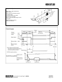
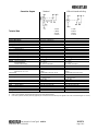
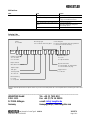
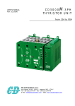
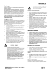
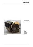
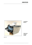
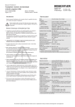
Introduction
This installation manual is provided for the connection and starting
procedure of your cutter.
Further informations like e.g. dimensioned drawings are available in our
Printers and Cutters Catalogue or on request. The devices of the type G
(0685.0 ...) model series are electric motor driven paper cutters. The paper
is cut by a double-edged rotary knife. Thus two cuts can be made per one
single turn of the knife. These models allow the following triggering of the
drive motors:
K = Cutting is triggered by applying nominal voltage
via mechanical SPDT contacts
Operating Instructions
•
•
•
•
•
The cutters of these model series are available in various versions,
depending on the paper width and the operating voltage.
Safety Instructions
This cutter is a quality product manufactured in accordance with
established electrical engineering standards. The unit has been delivered
from the factory in perfect conformance to safety regulations. To maintain
this condition, please observe all notes and warnings in this document!
•
Installation and mounting of electrical devices may only be
performed by an electrotechnical expert!
•
When installing and mounting the cutter, please observe the
demands made on the whole facility by the respective device safety
regulation.
•
The cutter may only be used for the purpose it was designed for – i.e.
for cutting paper strips.
•
The cutter is designed complying with EN 60950, protection class III.
To prevent dangerous structure-borne currents, the equipment has to
be run on safety extra-low voltage (SELV) and must be in an area of
equipotential bonding.
•
The cutter may only be operated within the limits specified by the
technical data. Maximum operating voltages must not be exceeded!
•
Hengstler Cutters are designed for industrial use.
•
Installation environment and cabling have a very significant
influence on Electromagnetic Compatibilty (EMC). When installing
the cutter sub-assembly in a complete unit, you should seek
guarantees from the manufacturer of the complete unit regarding
EMC.
Caution: Danger!
•
•
•
•
The rotary knife has two sharp cutting edges! Therefore never reach
into the cutting area, e.g. for removing jammed material! Only use
tweezers, tongs or the like for this purpose (do not damage the
knife)!
It is expressively emphasized that the cutter is to be started only
when completely installed, i.e. the knife is covered on all sides and
the material feed and delivery slot are dimensioned such that, e.g.,
small children cannot reach into the cutting area.
Installation or servicing works are to be carried out only when the
power supply lines are disconnected from the cutter!
If safe operation is not possible any more, the cutter has to be set out
of order and to be protected against unintended starting.
User Manual for Cutter Type G 0 685.0
Modification No.: 4110701CK1
•
Do not cut self-adhesive labels! The traces of adhesive will pollute
the rotary knife and impair safe operation!
During the cutting process, there must be no paper feed.
Please make sure that the cutter remains free from shreds of paper.
Having applied voltage, please ensure that the rotary knife is in home
position before paper is fed.
If the cutter doesn’t have internal switching (page 3 of 4), the user
must install a suitable safety switch to ensure that power is removed
from the cutter within a max. of 10 seconds in the event of a breakdown, such as a jammed cutter. If this is not done, the motor may be
damaged through overheating.
Do not use cleansing agents containing solvents.
Installation Instructions
•
•
•
•
•
The cutter must be installed in the intended unit before connecting
the power lines!
The cutter can be installed in any position. The strips cut off,
however, must not collect in the cutting area, thus blocking the
rotary knife!
The cutter is attached by means of two M3 screws.
Install the cutter in the unit/housing such that paper transport is
smooth. Electrically connect the cutter to the control system and
power supply when these are switched off. You will find the
connection diagrams of this model series on page 3 ”Connection
diagram” and on the units’ backs.
Wire the cutter’s connecting lead, such that it does not disturb any
function of the assembly and that it will not be damaged or
squeezed.
Preparations for use
(please observe the key of fig. „Designation of parts“ on page 2)
•
Make sure that the cutter is turned off. Slide the paper in the paper
feed direction indicated (10) through the paper channel (2).
If the rotary knife (3) is not in home position it will hinder the paper
strip from being slid through the channel.
You can put the rotary knife to home position in two different ways:
1. Insert a hex key, size 3, into the rotary knife’s shaft (7) and turn the
knife until it does not block the channel any longer. Then remove the hex
key from the shaft!
2. Turn on the assembly and conduct one cutting cycle without paper.
Perform a trial run with paper.
Ensure that the paper strips are fed to the cutter continuously and
properly and that the unit cuts them precisely.
2685576
Page 1 of 4
Designation of parts
1 Paper cutter – type G model series
2 Paper channel
3 Rotary knife (not visible when type G)
4 Connecting leads
5 Connection diagram (not visible)
6 Identification (not visible)
7 Shaft of rotary knife with hexagon socket
8 Knife guard
9 Sense of the knife´s rotation
10 Paper feed direction
User Manual for Cutter Type G 0 685.0
Modification No.: 4110701CK1
2685576
Page 2 of 4
Connection diagram
Standard
1 Green
2 White
3 Brown
4 Yellow
Technical Data
Circuit diagramm
External start pulse by
pulse length
switching level
Cutting cycle max.
Operating voltage VB
voltage tolerance
Current (at Tu = 20°C)
static current
making current
no-load current
cutting current 1)
Failure (e.g. blocked knife)
Climate operating temperature
storage temperature
medium relative humidity
Service life (number of cuts)
Noice emission
distance 30 cm, VB + 10 %
General design
Protection class (IEC 529)
Vibration performance (IEC 68-2-6)
Shock resistance (IEC 68-2-27)
Drop test (DBP DIN ISO 2206, 2233, 2248)
Mounting
Paper
channel width (L)
paper width
paper weight
Knife guard
1)
2)
Without internal switching
1 Green
2 White
3 Brown
4 Yellow
with internal switching and PTC (B)
SPDT contact, potential-free
≥ 120 ms, ≤ 250 ms
operating voltage VB
700 ms
12 VDC/24 VDC (SELV)
± 10 %
VB = 12 V:/ VB = 24 V:
2,4 A / 1,2 A
0,16 A / 0,08 A
0,66 A / 0,33 A
2,4 A / 1,2 A1)
-10 ... + 60°C
-40 ... + 70 °C
65% without condensation
1.0 Mio
200 g/m²
without internal switching (C)
700 ms
12 VDC/24 VDC (SELV)
± 10 %
VB = 12 V:/ VB = 24 V:
2,4 A / 1,2 A
0,16 A / 0,08 A
0,66 A / 0,33 A
2,4 A / 1,2 A2)
-10 ... + 60°C
-40 ... + 70 °C
65% without condensation
1.0 Mio
200 g/m²
75 dB (A)
as per EN 60950, protection class III
IP 10
10 ... 60 Hz; 0,7 mm p.p.
60 ... 500 Hz; 50 m/s2,
800 m/s²; 6ms
passed
2 sunk nuts M3 (moveable)
64 mm; 90 mm and 120 mm
L-3 mm .... L-15 mm
60 ... 300 g/m²
standard
75 dB (A)
as per EN 60950, protection class III
IP 10
10 ... 60 Hz; 0,7 mm p.p.
60 ... 500 Hz; 50 m/s2,
800 m/s²; 6ms
passed
2 sunk nuts M3 (moveable)
64 mm; 90 mm und 120 mm
L-3 mm .... L-15 mm
60 ... 300 g/m²
standard
After 10 seconds the PTC-resistor pull down the drive motor from operating voltage.
If the motor is jammed, the safety switching supplied by the customer must ensure that the power applied to the motor is limited after approx. 10 seconds.
User Manual for Cutter Type G 0 685.0
Modification No.: 4110701CK1
2685576
Page 3 of 4
Malfunctions
Result
Rotary knife does not move
Cause
-Operating voltage failure
-Defective connecting cable
-Defective trigger control
-Rotary knife blocked by paper shreds/ foreign
objects
Rotary knife does not return to home position
-Cause unknown
-Defective reset switch or gear
Measure
-Check the power supply
-Check the cutter´s connecting cable as well
as
the plug-in and soldered connections
-Check mechanical resp. electronic pulsers
-Switch off the appliance!
Remove paper shreds from cutting area!
Remove foreign objects!
-Please contact the manufacturer
-Please contact the manufacturer
Ordering Code
(see identification plate)
Se rie s
G = 0 6 8 5 .0
ABS
G
M ou n tin g type
0 0 = w ith ou t m ou n tin g pa rt s
2 5 0
O p e ra t in g volta ge
12 = 12 V DC
24 = 24 V DC
Pa pe r ch a n n e l
064; 090 and 120m m
Pa pe r w e ig h t
2 5 0 g/m ²
C u ttin g m ode
V 0 = fu ll cu t
K
C ircu it d ia gra m
B = w ith in t e rn a l bra ke sw itch in g a n d PT C
C = w ith ou t in te rn a l sw ith in g
0 0
/
S pe cia l ve rsio n *
0 = n on e
S = spe cia l ve rsio n
T ype of co n n e ctio n
0 = rou n d ca b le , t in p la te d e n ds
2 = rou n d ca b le w ith plu g
T rigge r co n tro l
K = con ta ct
K n ife fin ish in g
K = n on e
Z = tin pla te d
We apply customer specifications on special versions. If you don´t know these please call us for the specifications, indicationg the cutter´s item
number.
_____________________________________________________________
HENGSTLER GmbH
Tel.: +49 (0) 7424 890
P.O.B. 1151
Fax: +49 (0) 74 24 89210
D-78550 Aldingen
e-mail: [email protected]
Germany
Homepage:http://www.hengstler.com
User Manual for Cutter Type G 0 685.0
Modification No.: 4110701CK1
2685576
Page 4 of 4