1
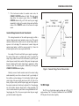
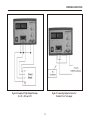
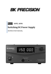
INSTRUCTION
MANUAL
MODEL 1671A
INSTRUCTION
MANUAL
MODEL 1671A
Triple Output
DC POWER SUPPLY
C
UL
US
TEST INSTRUMENT SAFETY
WARNING
Normal use of test equipment exposes you to a certain amount of danger from electrical shock because testing must
sometimes be performed where exposed high voltage is present. An electrical shock causing 10 milliamps of current to pass
through the heart will stop most human heartbeats. Voltage as low as 35 volts dc or ac rms should be considered dangerous
and hazardous since it can produce a lethal current under certain conditions. Higher voltages are even more dangerous. Your
normal work habits should include all accepted practices to prevent contact with exposed high voltage, and to steer current
away from your heart in case of accidental contact with a high voltage. Observe the following safety precautions:
There is little danger of electrical shock from the dc output of this power supply. However, there are several other possible test
conditions using this power supply that can create a high voltage shock hazard:
a. If the equipment under test is the "hot chassis" type, a serious shock hazard exists unless the equipment is unplugged (just
turning off the equipment does not remove the hazard), or an isolation transformer is used.
b. If the equipment under test is "powered up" (and that equipment uses high voltage in any of its circuits), the power supply
outputs may be floated to the potential at the point of connection. Remember that high voltage may appear at unexpected
points in defective equipment. Do not float the power supply output to more than 100 volts peak with respect to chassis or
earth ground.
c. If the equipment under test is "off" (and that equipment uses high voltage in any of its circuits under normal operation),
discharge high-voltage capacitors before making connections or tests. Some circuits retain high voltage long after the
equipment is turned off.
2. Use only a polarized 3-wire ac outlet. This assures that the power supply chassis, case, and ground terminal are connected to
a good earth ground and reduces danger from electrical shock.
3. Don't expose high voltage needlessly. Remove housings and covers only when necessary. Turn off equipment while making
test connections in high-voltage circuits. Discharge high-voltage capacitors after removing power.
1.
(Continued on inside back cover)
Instruction Manual
For
Model 1671A
Triple Output
DC POWER SUPPLY
B&K Precision Corporation
22820 Savi Ranch Parkway
Yorba Linda, California 92887
TABLE OF CONTENTS
Page
Page
TEST INSTRUMENT SAFETY.........................inside front cover
Constant Voltage/Current Characteristics.........................9
INTRODUCTION.........................................................................1
12 Vdc Output...................................................................9
SPECIFICATIONS........................................................................2
5 Vdc Output...................................................................10
CONTROLS AND INDICATORS................................................5
Dual or Triple Output............................................................10
OPERATING INSTRUCTIONS...................................................7
Connecting Outputs in Series................................................10
Safety Precautions...................................................................7
MAINTENANCE........................................................................12
Equipment Protection Precautions..........................................7
Fuse Replacement..................................................................12
Power Supply Hook-up and Operation....................................7
Instrument Repair Service.....................................................12
Variable Voltage Output....................................................7
SERVICE INFORMATION.........................................................13
Typical Constant Voltage Output......................................8
LIMITED ONE-YEAR WARRANTY........................................14
Setting Current Limit........................................................8
TEST INSTRUMENT SAFETY.........................inside back cover
Typical Constant Current Operation.................................8
i
ii
INTRODUCTION
The main output voltage and current are continuously
monitored by two digital LCD meters with resolution of 0.1 volt
and 0.01 amp.
The B+K Precision Model 1671A is a general purpose triple
output DC power supply. Their main outputs are versatile constant
voltage or constant current regulated power source that is variable
from 0 to 30 volts and 0 to 5 amps. An indicator lights in the
constant current mode, and serves as an overload indicator in the
constant voltage mode.
The Model 1671A can operate continuously at its maximum
rated output and is fully overload protected.
This manual provides the information to help assure the
maximum performance and longest life for your power supply.
While this model is competitively priced with most single
output power supplies, they have the added advantage of fixed 5
volt and 12 volt outputs capable of providing up to 0.5 amps each.
One common application for these power supply is powering of
circuit boards while troubleshooting. Many circuit boards require
two or three input voltages, with the most common values being 5
volts and 12 volts. These power supplies can provide up to three
outputs simultaneously. Since each output is fully isolated, any
output can be connected for positive or negative polarity.
1
SPECIFICATIONS
CONSTANT CURRENT MODE
LOAD REGULATION
OUTPUT NO. 1
≤0.4% + 10 mA
VOLTAGE
LINE REGULATION (108 TO 132 VAC)
Variable 0-30 VDC
≤0.4% + 10 mA
RIPPLE AND NOISE
CURRENT
≤ 10 mA rms
0 to 5 Amps
PROTECTION
POLARITY
Current limiting, short circuit protection, reverse polarity protection
Positive or Negative
VOLTAGE INDICATOR
CONNECTORS
3 digit LCD
Binding Posts
VOLTAGE RESOLUTION
REGULATION TYPE
0.1 V
Constant Voltage or Constant Current
VOLTAGE ACCURACY
CONSTANT VOLTAGE MODE
± (1% reading + 2 digit)
LOAD REGULATION (0 to rated output)
CURRENT INDICATOR
≤0.05% + 10 mV
3 digit LCD
LINE REGULATION (108 TO 132 VAC)
AMMETER RESOLUTION
≤0.05% + 10 mV
±0.01A
RIPPLE AND NOISE
AMMETER ACCURACY
≤5 mV rms
± (1% reading + 2 digit)
2
SPECIFICATIONS
OUTPUT NO. 3
OUTPUT NO. 2
VOLTAGE
VOLTAGE
Fixed 5 VDC ±5%
Fixed 12 VDC ±5%
CURRENT
CURRENT
0 to 500 mA continuous
0 to 500 mA continuous
POLARITY
POLARITY
Positive or Negative
Positive or Negative
CONNECTORS
CONNECTORS
Wire clips
Wire Clips
LOAD REGULATION (no load to 500 mA)
LOAD REGULATION (no load to 500 mA)
≤1%
≤1%
LINE REGULATION
LINE REGULATION
≤ 1%
≤ 1%
RIPPLE AND NOISE
RIPPLE AND NOISE
≤5 mV rms
≤5 mV rms
PROTECTION
PROTECTION
Short circuit protection, thermal overload protection
Short circuit protection, thermal overload protection
3
SPECIFICATIONS
COOLING
DIMENSIONS (H x W x D)
Variable speed thermal static control fan
4.9" x 8.5" x 11.5" (124 x 216 x 292mm)
AC INPUT
WEIGHT approx.
115/230 VAC, 50/60 Hz~ (~Alternate current)
14.3 lbs (6.5 kg)
POWER CONSUMPTION
ACCESSORIES SUPPLIED
265W
Instruction Manual
Spare fuse
OPERATION TEMPERATURE
0º TO 40º C, 10-80%R.H.
(80% relative humidity for temperature up to 31º C
decreasing linearly to 50% relative humidity at 40º C)
OPTIONAL ACCESSORIES
Power Supply Hook-up Cables, Model TL 5A
LINE SELECTION
The 1671A can operate on 115V AC or 230V AC line
input. Before connecting the power cord to the AC
outlet, make sure the voltage selector on the bottom of
the unit is set to the correct line voltage. Additionally,
please check that you have the fuse inserted in the
fuse box below the AC input receptacle. The fuse to
use is referenced below:
STORAGE TEMPERATURE
-15º TO 70º C, ≤ 85% R.H.
ENVIRONMENTAL CONDITIONS
-
10-80% R.H.
Altitude up to 2000m
Installation category: CAT II
Pollution degree: 2
Mains supply voltage fluctuation up to ±10% of normal voltage
LINE VOLTAGE
FUSE VALUE
4
115V
F4AL250V
230V
F2AL250V
CONTROLS AND INDCATORS
9. OUTPUT - Terminal (Black). Negative polarity variable
output terminal.
1. POWER Switch. Turns power supply on and off.
"I" : power switch ON
"O" : power switch OFF
2. Power ON light. Lights when power is turned on.
10. 12V OUTPUT + Terminal (red). Positive polarity 12 VDC
output terminal.
3. CURRENT LIMITED Indicator. Lights when variable
supply is operating in constant current mode.
11. 12V OUTPUT - Terminal (black). Negative polarity 12 VDC
output terminal.
4. CURRENT Control. Adjusts maximum output current of
variable supply. Read value on A meter
12. 5V OUTPUT - Terminal (black). Negative polarity 5 VDC
output terminal
5. VOLTAGE Control. Adjusts output voltage of variable
supply. Read value on V Meter.
13. 5V OUTPUT + Terminal (red). Positive polarity 5 VDC
output terminal.
6. A Meter. Indicates output current of variable supply.
14. POWER Input connector
7. V Meter. Indicates output voltage of variable supply.
15. FUSE Holder
8. OUTPUT + Terminal (Red). Positive polarity output
terminal.
16. DC Fan
5
CONTROLS AND INDICATORS
14
16
15
Figure 1. Front Panel Controls and Indicators,
Model 1671A
Figure 2. Rear Panel Model 1671A
6
OPERATING INSTRUCTIONS
the vent on top of the power supply. DO NOT place objects on top of the
power supply.
SAFETY PRECAUTIONS
CAUTION
Protection provided by the equipment may be impaired if the
equipment is used in a manner not specified by the manufacturer
Use only a polarized 3-wire outlet. This
assure s that the poser supply chassis and
case are connected to a good earth ground
and reduces danger of electrical shock
Don't put this product to a position so that it is difficult to unplug the
device from the appliance inlet
There is little danger of electric shock from the power supply output,
which produces a maximum of 30 volts dc. However, there may the great
danger of electrical shock if the power supply output is connected to an
external high voltage. Some equipment being powered may contain high
voltage and present a shock hazard. Observe caution. If the power supply
output is floated (referenced to a voltage rather than earth ground) turn off
the power supply and the equipment under test when making connections.
Never float the power supply to a potential greater than 100 volts peak
with respect to earth ground.
Unplug this product from the wall outlet before cleaning. Do not use
liquid cleaners or aerosol cleaners. Use a damp cloth for cleaning.
Although the power supply is protected against overload and short
circuits, avoiding these conditions in regular use results in maximum
stability and reliability.
Make certain that hook-up is as intended before turning power supply
on. Incorrect polarity may damage the equipment being powered.
Observe all TEST INSTRUMENT SAFETY precautions listed in the
front of this manual.
For indoor use only.
POWER SUPPLY HOOK-UP and OPERATION
EQUIPMENT PROTECTION PRECAUTIONS
Variable Voltage Output
1. Turn off the power supply and equipment being powered.
Avoid using the power supply in ambient temperatures above +40°C
(104°F). Always allow sufficient air space around the opening at the rear
of the power supply and the top and side vent openings for effective air
flow to prevent internal heat build-up. Typically, a two inch space at the
sides, as well as a six inch space at the top and rear of the power supply is
adequate. DO NOT block the fan opening at the rear of the power supply
or
NOTE
Use solid copper hook-up wire of at least 18 gauge. Using smaller wire
may increase the source resistance "seen" by the load, thereby derating the
regulation capabilities of the poser supply. Tighten connections snugly to
assure low resistance.
7
OPERATING INSTRUCTIONS
2.
Connect the red (+) OUTPUT terminal of the power supply to
the positive polarity input of the equipment being powered.
3.
Connect the black (-) OUTPUT terminal of the power supply to
the negative polarity input of the equipment being powered.
4.
Place the POWER switch to the ON position, the ON indicator
should illuminate,
5.
Setting Current Limit
1.
Determine the maximum safe current for the device to be
powered.
2.
Rotate the VOLTAGE control away from zero until some low
voltage (under 1 volt) is indicated.
3.
Temporarily short the (+) and (-) OUTPUT terminals of the
power supply together with a test lead
4.
Adjust the CURRENT control for the desired current limit. Read
the current value on the current display.
5.
The current limit (overload protection) has now been preset. Do
not change the CURRENT control setting after this step.
6.
Remove the short between the (+) and (-) OUTPUT binding
posts and hook up for constant voltage operation.
Turn on the equipment being powered.
Typical Constant Voltage Operation
1.
Before connecting the device to be powered to the power supply,
determine the maximum safe load current for the device to be
powered and set the current limit value (see "Setting Current
Limit" procedure in the is section).
2.
Set the VOLTAGE control to minimum (fully counterclockwise)
3.
Turn off power supply and connect it to the device to be powered
4.
Turn on POWER switch. The power ON indicator should light
5.
Increase the VOLTAGE setting until the voltage display reads
the desired value.
6.
Typical Constant Current Operation
If the load current exceeds the preset current limit, the
CURRENT LIMITED indicator will light. In this case, the
power supply automatically switches to the constant current
mode and further rotation of the VOLTAGE control will not
increase the output current.
8
1.
Before connecting the device to be powered to the power supply,
determine the maximum safe voltage to be applied, and set the
VOLTAGE control to obtain that voltage reading on the display.
2.
Determine the desired constant current value.
3.
Set the CURRENT control to minimum (fully counterclockwise).
4.
Turn off the power supply and connect it to the device to be
powered.
5.
Turn on the power supply.
6.
Increase the CURRENT control setting until the desired constant
current value is read on the display, or set the current limit in
advance (before connecting the load) as prescribed earlier in the
"setting Current Limit" procedure.
OPERATING INSTRUCTIONS
7.
If the load current reaches the constant current value, the
CURRENT LIMITED indicator will light. If the load current
drops below the constant current value, the CURRENT
LIMITED indicator will go off. In this case the power supply
automatically switches to the constant voltage mode, and further
rotation of the CURRENT control will not increase the output
current.
Constant Voltage/Constant Current Characteristic
The working characteristic of the variable power supply is called a
constant voltage/constant current automatic crossover type. This permits
continuous transition from constant current to constant voltage modes in
response to the lead change. The intersection of constant voltage and
constant current modes is called the crossover point. Fig 3 shows the
relations ship between this crossover points and the load.
For example, if the load is such that the power supply is operating in
the constant voltage mode, a regulated output voltage is provided. The
output voltage remains constant as the lad increases, up until the point
where the preset current limit is reached. At that point, the output current
becomes constant and the output voltage drops in proportion to further
increases in load. The crossover point is indicated by the front panel
CURRENT LIMITED indicator lighting.
Figure 3. Constant Voltage/Current Characteristics
Similarly, crossover from the constant current to the constant voltage
mode automatically occurs from a decrease in load. A good example of
this would be seen when charging a 12-volt car battery. Initially, the open
circuit voltage of the power supply may be preset for b 13.8 volts. A low
battery will place a heavy load on the power supply and it will operate in
the constant current mode, which may be adjusted of a 2 Amp charging
rate. AS the battery becomes charged, and its voltage approaches 13.8
volts, its load decreased to the point where it no longer demands the full 2
Amp charging rate. This is the crossover point where the power supply
goes into the constant voltage mode.
12 VDC Output
The 12 Vdc is a fixed voltage supply providing up to 500 mA (0.5
amp) continuous. The 12 Vdc output is available at the two left OUTPUT
12V tie points. Be sure to observe polarity.
9
OPERATING INSTRUCTIONS
5 VDC Output
DUAL OR TRIPLE OUTPUT
The 5 Vdc is a fixed voltage supply providing up to 500 mA (0.5 amp)
continuous. The 5 Vdc output is available at the two right OUTPUT 5V tie
points. Be sure to observe polarity.
Two of the outputs, or all three of the outputs may be used
simultaneously if desired. The three outputs are fully isolated from ground,
and each other, thus each output may be connected for the either positive
or negative polarity.
CAUTION
1.
2.
3.
A typical example of a triple output application would be powering a
circuit board that requires three voltages, such as +5, +12V and -12V. Fig.
4 shows how the outputs would be connected for this example, and the
following procedures reviews the steps of hook-up.
The 12V and 5V supplies will provide up to 1 amp
for a short period, but thermal shutdown may occur
when the output is overloaded for a few minutes.
Upon thermal shutdown there will be now output. If
thermal shutdown occurs, remove the load and wait
15 minutes for the power supply to cool. Normal
operation may then resume.
Overloading May also cause sever ripple I the output
which could disrupt operation of the circuit being
powered. Excessive ripple will produce a loud hum
in devices with speakers.
You can prevent overloading by measuring the
output current with an external multimeter. Set the
meter to measure current (a 2 amp range is desirable,
or a 10 amp range may be used) and connect is
"series" with the load. Load current up to 500 mA
may be operated continuously, load current greater
than 500 mA must be short term, maximum short
term current is 1 amp.
1.
The variable supply would be set for 12V. WE will assign the
variable supply as the +12V source and the fixed 12V supply as
the -12V source.
2.
Connect the - terminal of the 5V supply to circuit board common
and the + terminal to the +5V input of the board.
3.
Connect the - terminal of the variable supply to circuit board
common (or the terminal of the 5V supply). Connect the +
terminal of the variable supply to the +12V input of the board.
4.
Connect the + terminal of the fixed 12V supply to circuit board
common (or the - terminal of the 5V and variable supplies).
Connect the - terminal of the fixed 12V supply to the -12V input
of the board.
CONNECTING OUTPUTS IN SERIES
When the 30 volt output of the variable supply is not adequate, the
outputs may be connected in series to provide a variable 17 to 47 volt
output. Since the supplies are connected in series, the maximum current is
the same as for the fixed voltage supplies, that, 500 mA continuous or 1
amp peak. Connections for the configuration are shown in Fig. 5.
10
OPERATING INSTRUCTIONS
Figure 4. Example of Triple Output Hook-up
for +5V, +12V, and -12V
Figure 5. Connecting Outputs in Series for
Variable 17 to 47 volt output
11
MAINTENANCE
INSTRUMENT REPAIR SERVICE
WARNING
Because of the specialized skills and test equipment required for
instrument repair and calibration, many customers prefer to rely upon
B & K Precision for this service. We maintenance a network of B+K
Precision authorized service agencies for this purpose. To use this service,
even if the instrument is no longer under warranty, follow the instructions
given in the WARRANTY SERVICE INSTRUCTIONS section of this
manual. There is a nominal charge for instruments out or warranty.
The following instructions are for use by qualified
personnel only. To avoid electrical shock, do not perform
any servicing other than contained in the operating
instructions unless you are qualified to do so.
FUSE REPLACEMENT
If the fuse blows, the power on LED indicator will not light and the
power supply will not operate. The fuse should not normally open unless a
problem has developed in the unit. Try to determine and correct the cause
of the blown fuse, then replace only with a fuse of the correct rating. The
fuse is located on the rear panel (see Fig. 2).
LINE VOLTAGE
FUSE VALUE
115V
F4AL250V
230V
F2AL250V
12
Service Information
Warranty Service: Please return the product in the original packaging with proof of purchase to the address below. Clearly
state in writing the performance problem and return any leads, probes, connectors and accessories that you are using with the
device.
Non-Warranty Service: Return the product in the original packaging to the address below. Clearly state in writing the
performance problem and return any leads, probes, connectors and accessories that you are using with the device. Customers
not on open account must include payment in the form of a money order or credit card. For the most current repair charges
please visit www.bkprecision.com and click on "service/repair".
Return all merchandise to B&K Precision Corp. with pre-paid shipping. The flat-rate repair charge for Non-Warranty Service
does not include return shipping. Return shipping to locations in North American is included for Warranty Service. For
overnight shipments and non-North American shipping fees please contact B&K Precision Corp.
B&K Precision Corp.
22820 Savi Ranch Parkway
Yorba Linda, CA 92887
www.bkprecision.com
714-921-9095
Include with the returned instrument your complete return shipping address, contact name, phone number and
description of problem.
13
Limited One-Year Warranty
B&K Precision Corp. warrants to the original purchaser that its products and the component parts thereof, will be free from
defects in workmanship and materials for a period of one year from date of purchase.
B&K Precision Corp. will, without charge, repair or replace, at its option, defective product or component parts. Returned
product must be accompanied by proof of the purchase date in the form of a sales receipt.
To obtain warranty coverage in the U.S.A., this product must be registered by completing a warranty registration form online at
www.bkprecision.com within fifteen (15) days of purchase.
Exclusions: This warranty does not apply in the event of misuse or abuse of the product or as a result of
unauthorized alterations or repairs. The warranty is void if the serial number is altered, defaced or removed.
B&K Precision Corp. shall not be liable for any consequential damages, including without limitation damages resulting from
loss of use. Some states do not allow limitations of incidental or consequential damages. So the above limitation or exclusion
may not apply to you.
This warranty gives you specific rights and you may have other rights, which vary from state-to-state.
B&K Precision Corp.
22820 Savi Ranch Parkway
Yorba Linda, CA 92887
www.bkprecision.com
714-921-9095
14
(Continued from inside front cover)
4. If possible, familiarize yourself with the equipment being tested and the location of its high voltage points. However, remember that
high voltage may appear at unexpected points in defective equipment.
5. Use an insulated floor material or a large, insulated floor mat to stand on, and an insulated work surface on which to place equipment;
and make certain such surfaces are not damp or wet.
6. When testing ac powered equipment, the ac line voltage is usually present on some power input circuits such as the on-off switch,
fuses, power transformer, etc. "any time" the equipment is connected to an ac outlet, even if the equipment is turned off.
7. B+K Precision products are not authorized for use in any application involving direct contact between our product and the human
body, or for use as a critical component in a life support device or system. Here, "direct contact" refers to any connection from or to our
equipment via any cabling or switching means. A "critical component" is any component of a life support device or system whose
failure to perform can be reasonably expected to cause failure of that device or system, or to affect its safety or effectiveness.
8. Never work alone. Someone should be nearby to render aid if necessary. Training in CPR (cardio-pulmonary resuscitation) first aid is
highly recommended.
15
B&K Precision Corporation
22820 Savi Ranch Parkway
Yorba Linda, California 92887
www.bkprecision.com
©2005 B&K Precision Corporation
Printed in China
043014