1
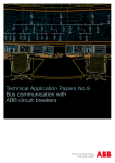
Annex to the technical catalogue
Emax DC
Low voltage switch-disconnectors
and automatic circuit-breakers for
Direct Current Applications
1SDC200012D0201
Phone: 800.894.0412 - Fax: 888.723.4773 - Web: www.clrwtr.com - Email: [email protected]
Index
SACE Emax DC automatic circuit-breakers . ........................................................................... 2
SACE Emax DC switch-disconnectors for applications up to 1000 V DC . ............................. 3
SACE Emax DC: Direct Current Applications .......................................................................... 4
Protection trip units and trip curves ......................................................................................... 8
Accessories ............................................................................................................................ 23
Overall dimensions ................................................................................................................. 24
Circuit diagrams ..................................................................................................................... 33
Ordering codes . ..................................................................................................................... 42
Phone: 800.894.0412 - Fax: 888.723.4773 - Web: www.clrwtr.com - Email: [email protected]
SACE Emax DC automatic circuit-breakers
The SACE Emax range of low voltage automatic circuit-breakers is being enriched by the new series
SACE Emax DC of automatic circuit-breakers for direct current applications in compliance with the
international standard IEC60947-2.
Thanks to the exclusive technology of the new electronic SACE PR123/DC e PR122/DC the SACE Emax
DC range allows to cover all installation and automatic protection needs up to 1000V / 5000A DC.
By connecting three breaking poles in series it is possible to achieve a rated voltage of 750V DC,
while with four poles in series the limit rises 1000V DC.
The automatic circuit-breakers of SACE Emax DC range maintain the overall dimensions and fixing
points of the standard range circuit-breakers; they can be fitted with the various terminal kits and all
accessories common to the SACE Emax range.
The withdrawable circuit-breakers should be used together with the special version fixed parts for
applications at 750/1000 DC.
Common data Voltages
Rated service voltage Ue
Rated insulation voltage Ui
Rated impulse withstand voltage Uimp
[V–]1000
[V]1000
[kV]12
Operating temperature
[°C]
-25....+70
Storage temperature
[°C]
-40....+70
Number of poles
Versions
3-4
Fixed -
E2 E3 E4 E6
Performance levels
B
N
N
H
S
H
H
Rated uninterrupted current (at 40 °C) Iu
[A]
800
800
[A]
1000
1000
[A]
1250
1250
1600 1600
[A]
1600
1600
1600
2000
2000
2000
[A]
[A]
2500
2500
2500
[A]
3200
3200
3200
4000
[A]
5000
[A]
Rated ultimate breaking capacity under short-circuit Icu
@ 500 V DC (III)
[kA]
35
50
60
85
75100100
@ 750 V DC (III)
[kA]
25
25
40
40
65
65
65
@ 750 V DC (IV)
[kA]
25
40
50
50
65
65
65
@ 1000 V DC (IV)
[kA]
25
25
35
40
50
65
65
Rated service breaking capacity under short-circuit Ics [%Icu] [kA]100%100%100%100%100%100%100%
Rated short-time withstand current Icw (0.5s)
@ 500 V DC (III)
[kA]
35
50
60
65
75100100
@ 750 V DC (III)
[kA]
25
25
40
40
65
65
65
@ 750 V DC (IV)
[kA]
25
40
50
50
65
65
65
@ 1000 V DC (IV)
[kA]
25
25
35
40
50
65
65
Rated making capacity under short-circuit Icm [%Icu] [kA]100%100%100%100%100%100%100%
Utilization category (according to CEI EN 60947-2)
B
B
B
B
B
B
B
■
■
■
■
■
■
■
Isolation behaviour (according to CEI EN 60947-2)
Overcurrent protection
Electronic trip units for DC applications
■
■
■
■
■
■
■
Operating times
80
80 80
80
80
80
Closing time (max)
[ms]
80
Breaking time for I<Icw (max) (1)
[ms]
70
70
70
70
70
70
70
Breaking time for I>Icw (max)
[ms]
30
30
30
30
30
30
30
Overall dimensions
Fixed: H = 418 mm - D = 302 mm - W (3/4 poles)
[mm]
296/386 296/386 404/530 404/530 566/656 566/656 782/908
Withdrawable: H = 461 mm - D = 396.5 mm - W (3/4 poles)
[mm]
324/414 324/414 432/558 432/558 594/684 594/684 810/936
Weights
Fixed 3/4 poles
[kg]
50/61
50/61
66/80
66/80
97/117 97/117140/160
Withdrawable 3/4 poles (including fixed part)
[kg]
50/61
50/61
66/80
66/80147/165147/165 210/240
(1) Without intentional delays.
Phone: 800.894.0412 - Fax: 888.723.4773 - Web: www.clrwtr.com - Email: [email protected]
SACE Emax Switch-disconnectors for
applications up to 1000V DC
ABB SACE has developed the SACE Emax/E MS range of switch-disconnectors for applications in
direct current up to 1000V in compliance with the international IEC 60947-3 Standard. These noautomatic circuit-breakers are specially suitable for use as bus ties or main isolators in direct current
systems, such as in applications involving electric traction.
The range covers all installation needs up to 1000V DC /6300A.
They are available in fixed and withdrawable, three-pole and four-pole versions.
By connecting three breaking poles in series, it is possible to achieve a rated voltage of 750V DC,
while with four poles in series the limit rises to 1000V DC.
The switch-disconnectors of the SACE Emax/E MS range maintain the overall dimensions and fixing
points of the standard range circuit-breakers. They can be fitted with the various terminal kits and all
the accessories common to the SACE Emax range. They cannot, of course, be associated with the
electronic trip units, CSs and accessories for determining currents and for AC applications.
The withdrawable circuit-breakers should be used together with the special version fixed parts for
applications at 750/1000V DC.
E1B/E MS
E2N/E MS
E3H/E MS
E4H/E MS* E6H/E MS*
Rated current (at 40 °C) Iu
[A] 800 1250 1250 3200 5000
[A] 1250 1600 1600 4000 6300
[A]
2000 2000 [A]
2500
[A]
3200
3 4
3 4
3 4
3 4
3 4
Poles 750 750
750 750
Rated service voltage Ue [V]
750 750
750 750
750 750
Rated insulation voltage Ui
[V]1000100010001000100010001000100010001000
Rated impulse withstand voltage Uimp [kV]12121212121212121212
40 40*
65 65
65 65
Rated short-time withstand current Icw (1s) [kA]
20 20*
25 25*
Rated making capacity Icm
750 V DC
[kA]
42 42
52.5 52.5105105143143143143
1000 V DC
[kA] 42 52.5105143143
Note: the breaking capacity Icu, by means of external protection relay, with 500 ms maximum timing, is equal to the value of Icw (1s).
* The performances at 750 V are:
for E1B/E MS Icw=25kA
for E2N/E MS Icw=40kA
for E3H/E MS Icw=50kA
Phone: 800.894.0412 - Fax: 888.723.4773 - Web: www.clrwtr.com - Email: [email protected]
SACE Emax DC: Direct Current Applications
The main applications of direct current are:
1. Emergency supply or auxiliary services: the use of direct current is due to the need to employ a
back-up energy source which allows the supply of essential services such as protection services,
emergency lighting, alarm systems, hospital and industrial services, data-processing centres etc.,
using accumulator batteries
2. Electrical traction: the advantages offered by the use of dc motors in terms of regulation and of
single supply lines lead to the widespread use of direct current for railways, underground railways,
trams, lifts and public transport in general
3. Particular industrial installations: there are some electrolytic process plants and applications which
have a particular need for the use of electrical machinery
4. Navy, Alternative Energy Conversion, …
Phone: 800.894.0412 - Fax: 888.723.4773 - Web: www.clrwtr.com - Email: [email protected]
SACE Emax DC: Direct Current Applications
Direct Current Network Typology
Here below the typical distribution systems used in direct current are described:
Both Polarities Insulated from Earth
– Fault a: the fault, without negligible impedance, between the two polarities sets up a short-circuit
current to which both polarities contribute to the full voltage, according to which the breaking
capacity of the breaker must be selected.
– Fault b, c: the fault between the polarity and earth has no consequences from installation functioning point of view.
One polarity connected to earth
– Fault a: the fault between the two polarities sets up a short-circuit current to which both polarities contribute to the full voltage U, according to which the breaking capacity of the breaker is
selected.
– Fault b: the fault on the polarity not connected to earth sets up a current which involves the
over-current protection according to the resistance of the ground.
– Fault c: the fault between the polarity connected to earth and earth has no consequences from
the point of view of the function of the installation.
All the poles of the breaker necessary for protection must be connected in series on the non-earthed
polarity.
Phone: 800.894.0412 - Fax: 888.723.4773 - Web: www.clrwtr.com - Email: [email protected]
SACE Emax DC: Direct Current Applications
Direct Current Network Typology
Median Point connected to Earth
– Fault a: the fault between the two polarities sets up a short-circuit current to which both polarities contribute to the full voltage U, according to which the breaking capacity of the breaker is
selected.
– Fault b: the fault between the polarity and earth sets up a short-circuit current less than that of
a fault between the two polarities, as it is supplied by a voltage equal to 0.5 U.
– Fault c: the fault in this case is analogous to the previous case, but concerns the negative polarity.
The breaker must be inserted on both polarities.
Phone: 800.894.0412 - Fax: 888.723.4773 - Web: www.clrwtr.com - Email: [email protected]
SACE Emax DC: Direct Current Applications
Circuit Breaker Selection
To correctly select the devices for the protection of a direct current network the following factors
must be considered:
• The type of network - earthing connection
• Rated Current
• Voltage Current
• The prospective short-circuit current at the point of installation
Here below the rating plate of an Emax DC air circuit-breaker for direct current application:
INCOMING POWER FROM UPPER TERMINALS
INCOMING POWER FROM BOTTOM TERMINALS
Phone: 800.894.0412 - Fax: 888.723.4773 - Web: www.clrwtr.com - Email: [email protected]
Protection trip units and trip curves
PR122/DC
Characteristics
The PR122/DC is the new electronic protection trip unit for the SACE Emax DC series suitable for
direct current installation wherein the basic protections are enough.
The PR122/DC offers the following protection functions:
• Overload (L);
• Selective short-circuit (S);
• Thermal memory for S and L (cable protection);
• Instantaneous short-circuit (I);
• Overtemperature protection (OT);
• Zone selectivity for S;
• Load Control (K).
Phone: 800.894.0412 - Fax: 888.723.4773 - Web: www.clrwtr.com - Email: [email protected]
Protection functions and setting values - PR122/DC
Function
Trip
threshold
Threshold
steps
Trip
Time
Time
Step
Poss. excl.
Relation Thermal
Zone
t=f(I) memory selectivity
Overload I1= 0.4….1 x In
0.01 x In
protection
(2)
Tolerance Release between
1.05 and 1.2 x I1
With current I = 3 x I1
3 s (1)
–
t1= 3 s....102 s
± 10% If ≤ 6 x In
± 20% If > 6 x In
Selective short- circuit protection
I2= 0.6….10 x In 0.1 x In
± 7% If ≤ 6 x In Tolerance (2)
± 10% If > 6 x In
With current I > I2
t2= 0.05 s….0.35 s t2sel= 0.04 s…..0.2 s
The better of the two figures:
± 10% or ± 40 ms
I2= 0.6….10 x In 0.1 x In
Tolerance (2)
± 7% If ≤ 6 x In
± 10% If > 6 x In
With current I = 10 x In
t2= 0.05 s….0.35 s
0.01 s
■
t=k/I2
± 15% If ≤ 6 x In
± 20% If > 6 x In
Instantaneous
short-circuit
protection I3= 1.5….10 x In
0.1 x In
Instantaneous
0.01 s
0.01 s
–
■
■
IEC60255-8
■
–
t=k
–
■
■
–
–
–
–
–
t=k
Tolerance (2)
± 10% ≤ 30 ms
OT
May not be set
Instantaneous
Protection against
overtemperature
–
–
–
temp=k
(1) The minimum trip value is 1 s, regardless of the type of curve set (self-protection)
(2) These tolerances are valid in the following conditions:
- fully powered release by voltage module and/or auxiliary power supply (without start-up)
- trip time set ≥ 100 ms
The following tolerance values apply in all cases not covered by the above:
Trip threshold
L
Release between 1.05 and 1.25 x I1 ± 20%
Trip time
S ± 10% ± 20%
I
≤ 60ms
± 15%
Others
± 20%
Phone: 800.894.0412 - Fax: 888.723.4773 - Web: www.clrwtr.com - Email: [email protected]
Protection trip units and trip curves
PR122/DC
Power Supply
The PR122/DC trip unit does not normally require an auxiliary power supply being self-supplied from
the measurement module PR120/V always supplied as standard in PR122/DC (only for power supply,
no voltage and power based protection/measurements available in PR122/DC).
On request it is possible to supply the PR122/DC with a special version of measurements module
suitable for very low DC rated voltage 24/48V DC, called PR120/LV, typically railway and mine installations.
An external auxiliary power supply is however required in case of the PR120/LV module is present.
Power supply from Measurement Module Minimum Voltage Threshold
Enabling Unit PR122/DC
PR120/V
70 V
When an auxiliary power supply is present, refer to the below table for the overall electronic power
consumption.
PR122/DC
PR120/D-M
PR120/K
Auxiliary power supply 24 V DC ± 20%
from PR122/DC
from PR122/DC
(galvanically insulated)
Maximum ripple 5%
Inrush current @ 24V
~10 A for 5 ms
Rated power @ 24V
~3 W
+1 W
+1 W
The Emax DC is supplied as standard for incoming power from the bottom terminals: PR120/V
- PR120/LV internal connection on bottom terminals – “U rear connection kit” mounted on upper
terminals.
Refer to Ordering Codes Section for incoming power from the upper terminals.
1
Phone: 800.894.0412 - Fax: 888.723.4773 - Web: www.clrwtr.com - Email: [email protected]
Functions L-S-I
t=k
Functions L-S-I
I2t = k
Phone: 800.894.0412 - Fax: 888.723.4773 - Web: www.clrwtr.com - Email: [email protected]
Protection trip units and trip curves
PR123/DC
Characteristics
The PR123/DC is the new electronic protection trip unit for the SACE Emax DC series; the complete
range of protection functions together with the wide combination of thresholds and trip times offered
make it suitable for protecting a wide range of direct current installation.
The PR123/DC offers the following protection functions:
• Overload (L);
• Selective short-circuit (S);
• Thermal memory for L and S (cable protection);
• Instantaneous short-circuit (I);
• Earth fault with adjustable delay (G);
• Poles unbalance (U);
• Overtemperature protection (OT);
• Load control (K);
• Undervoltage (UV);
• Overvoltage (OV);
• Reverse power (RP);
• Dual setting;
• Zone selectivity for S, G;
• Start-up thresholds for protection S and I.
Phone: 800.894.0412 - Fax: 888.723.4773 - Web: www.clrwtr.com - Email: [email protected]
Protection functions and setting values - PR123
Function
Trip
threshold
Threshold Trip
steps
Time
Time
Step
Can be
excluded
Relation Thermal
Zone
memory selectivity
t=f(I) Overload
protection
I1= 0.4….1 x In
0.01 x In
Release between Tolerance (2)
1.05 and 1.2 x I1
I1= 0.4….1 x In
0.01 x In
Tolerance
Release between 1.05 ... 1.2 x I1
Selective short-circuit protection
I2= 0.6….10 x In
0.1 x In
± 7% If ≤ 6 x In Tolerance (2)
± 10% If > 6 x In
I2= 0.6….10 x In
0.1 x In
± 7% If ≤ 6 x In
Tolerance (2)
± 10% If > 6 x In
Selective short-circuit I2= 0.6….10 x In
0.1 x In
protection
± 7% If ≤ 6 x In Tolerance (2)
± 10% If > 6 x In
Instantaneous
short-circuit
protection
I3= 1.5….10 x In
0.1 x In
± 10%
Tolerance (2)
Earth fault protection I4= 0.2….1 x In
0.02 x In
(2)
Tolerance ± 7% I4= 0.2….1 x In
0.02 x In
± 7% Tolerance (2)
U
Phase unbalance I6= 5%….90%
5%
protection ± 10%
Tolerance (2)
Protection against
OT
overtemperature cannot be set
–
With current I = 3xI1
t1= 3 s....102 s
3 s (1)
–
IEC60255-8
± 10% If ≤ 6 x In
± 20% If > 6 x In
With current I = 3xI1; t1= 3 s....144 s
3s
–
t=k(α)
± 20% If > 5 x I1
α = 0.2-1-2
± 30% 2xI1≤ If ≤ 5 x I1 With current I > I2
t2= 0.05 s….0.35 s
0.01 s
■
t=k
t2sel= 0.04 s…..0.2 s
0.01 s
The better of the two figures:
± 10% or ± 40 ms With current I = 10xIn; t2= 0.05 s…0.35 s 0.01 s
■
t=k/I2
± 15% If ≤ 6 x In
± 20% If > 6 x In
With current I > I2
t2= 0.05 s….0.35 s
0.01 s
■
t=k
The better of the two figures:
± 10% or ± 40 ms Undervoltage I8= 0.5….0.95 x Un
0.01 x In
UV
protection ± 5%
Tolerance (2) Overvoltage I9= 1.05….1.2 x Un
0.01 x In
OV
protection (2)
± 5%
Tolerance RP
Reverse
power P11= -0.3….-0.1 x Pn 0.02 Pn
protection ± 10%
Tolerance (2)
With current U < U8; t8= 0.1 s….5 s 0.1 s
The better of the two figures:
± 20% or ± 40 ms
With current U > U9; t9= 0.1 s….5 s 0.1 s
The better of the two figures:
± 20% or ± 40 ms
With current P < P11
t11= 0.5 s…..25 s
0.1 s
The better of the two figures:
± 10% or ± 100 ms
(1)
(2)
Instantaneous
–
■
t=k
≤ 30 ms
With current I > I4
t4= 0.1 s…..1 s
0.05 s
■
t=k
t4sel= 0.04 s…..0.2 s
0.01 s
The better of the two figures:
± 10% or ± 40 ms
t4= 0.1 s…..1 s (with I=4xI4)
0.05 s
■
t=k/I2
± 15%
t6= 0.5 s…..60 s
0.5 s
■
t=k
The better of the two figures:
± 20% or ± 100 ms
Instantaneous
–
■
–
–
■
■
–
–
■
–
–
–
■
–
–
–
–
–
temp=k
–
–
■
t=k
–
–
■
t=k
–
–
■
t=k
–
–
The minimum trip value is 1 s, regardless of the type of curve set (self-protection)
These tolerances hold in the following conditions:
-fully powered release by voltage module and/or auxiliary power supply (without start-up)
- trip time set ≥ 100 ms
The following tolerance values apply in all cases not covered by the above:
Trip threshold
L Release between 1.05 and 1.25 x I1
S ± 10% I ± 15%
G ± 15%
Others
Trip time
± 20%
± 20%
≤ 60ms
± 20%
± 20%
Phone: 800.894.0412 - Fax: 888.723.4773 - Web: www.clrwtr.com - Email: [email protected]
Protection trip units and trip curves
PR123/DC
Power Supply
The PR123/DC trip unit does not normally require an auxiliary power supply being self-supplied from
the measurement module PR120/V always supplied as standard in PR123/DC.
On request it is possible to supply the PR123/DC with a special version of measurements module
suitable for very low DC rated voltage 24/48V DC, called PR120/LV, typically railway and mine installations.
An external auxiliary power supply is however required in case of the PR120/LV module is present.
Power supply from Measurement Module Minimum Voltage Threshold
Enabling Unit PR123/DC
PR120/V
70 V
When an auxiliary power supply is present, refer to the below table for the overall electronic power
consumption.
PR123/DC
PR120/D-M
PR120/K
Auxiliary power supply 24 V DC ± 20%
from PR122/DC
from PR122/DC
(galvanically insulated)
Maximum ripple 5%
Inrush current @ 24V
~10 A for 5 ms
Rated power @ 24V
~3 W
+1 W
+1 W
The Emax DC is supplied as standard for incoming power from the bottom terminals: PR120/V
- PR120/LV internal connection on bottom terminals – “U rear connection kit” mounted on upper
terminals.
Refer to Ordering Codes Section for incoming power from the upper terminals.
Phone: 800.894.0412 - Fax: 888.723.4773 - Web: www.clrwtr.com - Email: [email protected]
Functions L-S-I
t=k
Functions L-S-I
I2t = k
Phone: 800.894.0412 - Fax: 888.723.4773 - Web: www.clrwtr.com - Email: [email protected]
Protection trip units and trip curves
PR123/DC
Function G
t=
k
I2
1SDC200112F0001
t=k
Function U
1SDC200122F0001
U
Phone: 800.894.0412 - Fax: 888.723.4773 - Web: www.clrwtr.com - Email: [email protected]
Function RP
1SDC200126F0001
RP
Function UV
1SDC200123F0001
UV
Phone: 800.894.0412 - Fax: 888.723.4773 - Web: www.clrwtr.com - Email: [email protected]
Protection trip units and trip curves
PR123/DC
Function OV
1SDC200124F0001
OV
Phone: 800.894.0412 - Fax: 888.723.4773 - Web: www.clrwtr.com - Email: [email protected]
Protection trip units and trip curves
Override Protection
The automatic circuit-breakers of SACE Emax DC range are supplied of an internal back-up protection
called Override Protection made by the Module PR120/DC always supplied with the PR122/DC
and PR123/DC electronic trip units.
The Override Protection ensures the protection of the electrical plant against instantaneous shortcircuit in case of any loss of power supply of the protection unit PR122/DC and PR123/DC.
The Override protection threshold depends on the circuit breaker size; as standard neither connections nor settings are in user’ care.
Phone: 800.894.0412 - Fax: 888.723.4773 - Web: www.clrwtr.com - Email: [email protected]
Protection trip units and trip curves
PR123/DC
Optional Modules for Electronic Trip units
The electronic trip units PR122/DC and PR123/DC can be equipped with the same internal optional
modules already available on the electronic devices PR122/P and PR123/P for alternative current
application.
Code
Internal
Description
PR123/DC
1SDA058255R1
PR120/K
Internal signalling module ■
(4 output with independent terminals)
1SDA058256R1
PR120/K
Internal signalling module (4 output + 1 input with a common terminal)
■
1SDA058254R1
PR120/D-M
Modbus RTU communication module ■
1SDA058252R1(1)
PR120/LV
Measurements module ■
1SDA065223R1(2)
PR120/LV
Measurements module - low voltage ■
PR120/DC
Override protection module ■
(3)
(1) PR120/V Measurements Module always supplied with the trip units PR123/DC and PR122/DC
(2) Extracode to be specified with the circuit-breaker code to have the low voltage measuring module PR120/LV
(3) Not to be specified, always supplied with the electronic trip unit
Code
External
Description
1SDA058258R1
PR030/B
Power supply unit PR123/DC
■
1SDA058259R1
BT030
External communication wireless unit ■
1SDA063143R1
HMI030
Interface from front of panel ■
1SDA048964R1
PR010/T
External test unit ■
1SDA059146R1
PR021/K
External signalling unit ■
1SDA052927R1
ATS010
Automatic transfer switch ■
1SDA060198R1
EP010
ABB Fieldbus plug ■
Phone: 800.894.0412 - Fax: 888.723.4773 - Web: www.clrwtr.com - Email: [email protected]
Protection trip units and trip curves
Measurements
PR122/DC
The following measurements are available
• Current;
• Instantaneous current value over a given time interval;
• Maintenance: number of operations, percentage of contact wears, opening data storage (latest
20 trips and 80 events);
• The protection records the historical data of the maximum current read.
PR123/DC
• Current;
• Maintenance: number of operations, percentage of contact wears, opening data storage (latest
20 trips and 80 events);
• Voltage;
• Instantaneous current/voltage value over a given time interval (data logger);
• Power;
• Energy;
• The protection records the historical data of the maximum current read, the maximum and minimum
voltage, the total maximum and mean value of power.
Phone: 800.894.0412 - Fax: 888.723.4773 - Web: www.clrwtr.com - Email: [email protected]
Protection trip units and trip curves
Measurements
Measurement Functions
The measurements available on electronic trip units PR122/DC and PR123/DC fitted by the Modbus
Communication module PR120/D-M and the protocol converter for Profibus and Devicenet FieldBus
EP010-FBP are listened on the following table.
PR122/DC
+ PR120/D-M
Communication functions
PR123/DC
PR122/DC-PR123/DC
+ PR120/D-M + PR120/D-M
and EP010
Protocol
Modbus RTU
Modbus RTU FBP
Physical layer
RS-485
RS-485
Profibus-DP or
DeviceNet cable
Maximum baudrate19200 bps19200 bps115 kbps
Measuring functions
Currents
Ground current
Voltage Power Energy Signalling from functions
LED: auxiliary power supply, warning, alarm
Temperature
Indication for L, S, I, G and other protection
Available data
Circuit-breaker status (open, closed)
Circuit-breaker position (racked-in, racked-out)
Mode (local, remote)
Protection parameters set
Load control parameters
Alarms
Protection L
Protection S
Protection I
Protection G
Fault release mechanism failure Undervoltage, overvoltage (timing and trip) protection
Reverse power protection (timing and trip)
Maintenance
Total number of operations
Total number of trips
Number of trip tests
Number of manual operations
Number of separate trips for each protection function
Contact wear (%)
Record data of last trip
Operating mechanisms
Circuit-breaker open/close
Reset alarms
Setting of curves and protection thresholds
Synchronize system time
Events
Status changes in circuit-breaker, protections and all alarms
■
■
■
■
■
■
■
■
■
on demand (1)
on demand (1)
on demand (1)
■
■
■
■
■
■
■
■
■
■
■
■
■
■
■
■
■
■
■
■
■
■
■
■
■
■
■
■
■
■
■
■
■
■
■
■
■
■
■
■
on demand (1)
on demand (1)
■
■
■
■
■
■
■
■
■
■
■
■
■
■
■
■
■
■
■
■
■
■
■
■
■
■
■
■
■
■
■
■
■
■
■
■
(1) please ask ABB for further details
Phone: 800.894.0412 - Fax: 888.723.4773 - Web: www.clrwtr.com - Email: [email protected]
Accessories
Electrical and Mechanical Accessories
Accessories
The SACE Emax DC family can be fitted by the same electrical and mechanical accessories already
available on the standard alternative current family.
The ranges
Automatic circuit-breakers
Switch-disconnectors
Circuit-breakers with
full-size neutral
Switch-disconnectors
for applications up to 1150V AC
Circuit-breakers for
applications
up to 1150V AC
Switch-disconnectors
for applications up to 1000V DC
Circuit-breaker version
Fixed Withdrawable
Fixed
Isolating
truck
(CS)
Earthing
switch
with
making
capacity
(MPT)
Earthing
truck
(MT)
Withdrawable Withdrawable Withdrawable Withdrawable
1a) Shunt opening/closing release (YO/YC)
and second opening release (YO2)
■
■
■
■
1b) SOR test unit
■
■
■
■
2a) Undervoltage release (YU)
■
■
■
■
2b) Time-delay device for undervoltage release (D)
■
■
■
■
■ (YC)
3) Geared motor for the automatic charging ■
■
■
■
■
of the closing springs (M)
4a) Electrical signalling of electronic releases tripped ■
■
4b) Electrical signalling of electronic releases tripped ■
■
with remote reset command
5a) Electrical signalling of circuit-breaker open/closed (1)
■
■
■
■
■
5b) External supplementary electrical signalling ■
■
■
■
■
of circuit-breaker open/closed
5c) Electrical signalling of circuit-breaker racked-in/
■
■
■
■
■
test isolated/racked-out
5d) Contact signalling closing springs charged
■
■
■
■
5e) Contact signalling undervoltage release
de-energized (C. Aux YU)
■
■
■
■
■
6a) Current transformer for neutral conductor ■
■
outside circuit-breaker
6b) Homopolar toroid for the main power supply earthing
conductor (star center of the transformer)
■
6c) Homopolar toroid for residual current protection
■
■
7) Mechanical operation counter
■
■
■
■
■
8a) Lock in open position: key
■
■
■
■
■
8b) Lock in open position: padlocks
■
■
■
■
■
■
8c) Circuit-breaker lock in racked-in/racked-out/
■
■
■
■
■
test isolated position
8d) Accessories for lock in racked-out/test isolated position
■
■
■
■
■
8e) Accessory for shutter padlock device
■
■
■
■
■
8f) Mechanical lock for compartment door
■
■
■
■
■
9a) Protection for opening and closing pushbuttons
■
■
■
■
■
■
9b) IP54 door protection
■
■
■
■
10) Interlock between circuit-breakers (2)
■
■
■
■
11) Automatic transfer switch - ATS010 (3)
■
■
■
■
CAPTION
■ Accessory on request for fixed circuit-breaker or moving part
■ Accessory on request for fixed part
■ Accessory on request for moving part
(1) For automatic circuit-breakers, four auxiliary contacts to electrically signal circuit-breaker
open/closed are included in the supply as standard.
(2) Incompatible with the E6/f versions with full-size neutral
(3) Incompatible with the range of circuit-breakers for applications up to 1150V AC
For Emax DC circuit-breakers accessories please refer to the same accessories codes of standard Emax AC circuit-breakers.
Phone: 800.894.0412 - Fax: 888.723.4773 - Web: www.clrwtr.com - Email: [email protected]
Overall dimensions
Fixed circuit-breaker
Basic version
with rear terminals
INCOMING POWER FROM UPPER TERMINALS 6
4 POLES
E2 - E4
E3 - E6
3 POLES
3 POLES
4 POLES
INCOMING POWER FROM BOTTOM TERMINALS 7
Caption
1 Inside edge of compartment
door
2 Segregation (when provided)
3 M10 mounting holes for
circuit-breakers (use M10
screws)
41xM12 screw (E1, E2, E3) or 2xM12 screws (E4, E6) for earthing (included in
the supply)
5 Insulating wall or insulated metal wall
6 In case of incoming power
from UPPER terminals –
PR120/V internal connection
on upper terminals and
U rear connection kits on
bottom terminals
7 In case of incoming power
from BOTTOM terminals –
PR120/V internal connection
on bottom terminals and U
rear connection kits on upper
terminals
A
B
C
D
E2
386
296148148
E3
530
404
202
202
E4
E6
746
566
238
328
1034
782
328
454
E2 III
View A
E2 IV
View A
397
Iu=1250A
Iu=1600A
90
90
90
145
100
Iu=1250A
Iu=1600A
65
148
252
98
78
242 177
M10
45
49
Max. 40
330
Iu=800A
Iu=1000A
100
145
65
148
98
Iu=800A
Iu=1000A
78
90
90
90
Phone: 800.894.0412 - Fax: 888.723.4773 - Web: www.clrwtr.com - Email: [email protected]
577
E4 III
View A
180
180
325
Iu=2500A
Iu=3200A
325
150
65
280
65
45
188
188
98
78
78
180
252
180
Iu=1600A
Iu=2000A
150
242
177
M10
45
Max. 40
98
60
10
10
49
98
10
50
78
510
757
E4 IV
View A
180
Iu=2500A
Iu=3200A
180
180
280
325
325
280
65
65
45
188
98
188
78
78
180
180
252
242
Iu=1600A
Iu=2000A
150
177
49
60
10
M10
45
10
Max. 40
98
10
50
78
690
211
415
E3 III
View A
95
Iu=2000A
Iu=2500A
126
126
114
96
168
98
98
78
148
78
126
126
242
177
96
12
252
10
M10
12
49
Max. 40
98
10
12
98
Iu=800A
Iu=1000A
Iu=1250A
Iu=1600A
50
78
348
Phone: 800.894.0412 - Fax: 888.723.4773 - Web: www.clrwtr.com - Email: [email protected]
Overall dimensions
Fixed circuit-breaker
Basic version
with rear terminals
541
E3 IV
View A
126
Iu=2000A
Iu=2500A
126
126
148
98 78
78
96
12
252
211
95
168
98
126
114
95
96
126
126
10
177
242
M10
63
49
12
12
98
Max. 40
Iu=800A
Iu=1000A
Iu=1250A
Iu=1600A
10
50
78
474
793
252
252
E6 III
View A
410
222
79,5
85
56
208
98
78
10
177
252
222
70
56
12
12
56
10
12
242
M10
50
98
78
49
Max. 40
63
726
1045
252
252
252
E6 IV
View A
410
182
56
85
85
208
98
56
12
78
177
252
222
70
10
10
12
12
56
242
M10
98
50
78
49
Max. 40
63
978
Phone: 800.894.0412 - Fax: 888.723.4773 - Web: www.clrwtr.com - Email: [email protected]
Compartment dimensions
A
B
E2
400
490
E3
500
630
E4
700
880
E6
10001260
Depth
3 POLES
4 POLES
Through-holes for flexible cables for mechanical
interlocks
Drilling of compartment door
N° 2 holes for IP54
protection cover
Phone: 800.894.0412 - Fax: 888.723.4773 - Web: www.clrwtr.com - Email: [email protected]
Overall dimensions
Withdrawable circuit-breaker
Basic version with
rear terminals
INCOMING POWER FROM UPPER TERMINALS 6
4 POLES
E2-E4
3 POLES
E3-E6
3 POLES
4 POLES
INCOMING POWER FROM BOTTOM TERMINALS 7
Caption
E2 III
View A
A
B
C
D
E2
414
324162162
E3
558
432
216
216
E4
774
594
252
342
E6
1062
810
342
468
417
327
145
100
100
103
Iu=1250A
Iu=1600A
53 33
103
53
33
174
225
380
393,5
0
380
Ø1
0
129
393,5
90
90
90
90
90
225
45
240
220
145
Iu=800A
Iu=1000A
100
65
103
53 33
65
90
53
100
33
90
90
90
90
10
10
53 33
Iu=1250A
Iu=1600A
175
100
138
145
60
10
10
50
240
70 49
70 240
103
E2 IV
View A
Ø1
1 Inside edge of compartment
door
2 Segregation (when provided)
3 M10 mounting holes for
circuit-breakers (use M10
screws)
41xM12 screw (E1, E2, E3) or 2xM12 screws (E4, E6) for earthing (included in
the supply)
5 Insulating wall or insulated metal wall
6 In case of incoming power
from UPPER terminals –
PR120/V internal connection
on upper terminals and
U rear connection kits on
bottom terminals
7 In case of incoming power
from BOTTOM terminals –
PR120/V internal connection
on bottom terminals and U
rear connection kits on upper
terminals
10
53 33
Iu=800A
Iu=1000A
60
10
50
Phone: 800.894.0412 - Fax: 888.723.4773 - Web: www.clrwtr.com - Email: [email protected]
597
180
E4 III
View A
180
325
325
280
Iu=2500A
Iu=3200A
280
65
143
53
10
530
7
180
400
53
10
10 10
10
10
Iu=1600A
Iu=2000A
50
33
122
120
E4 IV
View A
777
180
180
180
Iu=2500A
Iu=3200A
325
280
65
143
143
33
708
0
Ø1
33
40
380
33
180
45
380 84
53
528
33
40
393,5
393,5
103
33
Ø10
53
65
143
65
103
53
33
180
180
45
700
10
7
580
84
325
280
10
53
122
180
10
10 10
Iu=1600A
Iu=2000A
10
50
33
120
435
126
126
211
211
E3 III
View A
158
Iu=2000A
Iu=2500A
95
123
53
103
0
7
84
240
183
10
225
12
122
49
6
200
53
33
126
Ø1
33
40
380
95
33
183
393,5
114
70
63 33
126
12
10
12
50
Iu=800A
Iu=1000A
Iu=1250A
Iu=1600A
400
Phone: 800.894.0412 - Fax: 888.723.4773 - Web: www.clrwtr.com - Email: [email protected]
Overall dimensions
Withdrawable circuit-breaker
Basic version with
rear terminals
561
E3IV
View A
211
95
Iu=2000A
Iu=2500A
158
33
103
10
246
126
126
126
63
Ø
53
393,5
211
114
95
123
33
126
33
380
40
7
10
122
49
6
126
Iu=800A
Iu=1000A
Iu=1250A
Iu=1600A
12
240
63
84
126
225
10
12
70
53
325
12
50
33
370
490
813
463
E6 III
View A
410
252
85
252
163
53
33
222
744
Ø10
393,5
380
182
12
33
40
10
7
84
12
750
53
122
10
12
50
33
63
620
1065
463
E6 IV
View A
410
410
252
252
252
85
163
53
222
33
182
12
393,5
380
10
33
40
7
84
12
53
33
10
12
50
122
866
63
Phone: 800.894.0412 - Fax: 888.723.4773 - Web: www.clrwtr.com - Email: [email protected]
Compartment dimensions
A
B
E2
400
490
E3
500
630
E4
700
880
E6
10001260
Depth
3 POLES
4 POLES
Through-holes for flexible cables for mechanical
interlocks
Drilling of compartment door
N° 2 holes for IP54
protection cover
Phone: 800.894.0412 - Fax: 888.723.4773 - Web: www.clrwtr.com - Email: [email protected]
Overall dimensions
Circuit-breaker accessories
Mechanical
compartment
door lock Holes in compartment door
Minimum distance between circuit-breakers and switchboard wall
Fixed version
Withdrawable version
A
3 POLES 4 POLES
E2
180180
E3
234
E4
270
360
E6
360
486
234
Phone: 800.894.0412 - Fax: 888.723.4773 - Web: www.clrwtr.com - Email: [email protected]
Circuit diagrams
Reading information
Warning
Before installing the circuit-breaker, carefully read note F on the circuit diagrams.
Operating status shown
The circuit diagram is for the following conditions:
- withdrawable circuit-breaker, open and racked-in
- circuits de-energised
- releases not tripped
- motor operating mechanism with springs discharged.
Versions
Though the diagram shows a circuit-breaker in withdrawable version, it can be applied to a fixed version circuit-breaker
as well.
Fixed version
The control circuits are fitted between terminals XV (connector X is not supplied).
With this version, the applications indicated in figures 31 and 32 cannot be provided.
Withdrawable version
The control circuits are fitted between the poles of connector X (terminal box XV is not supplied).
Version with PR122/DC electronic trip unit
Version with PR123/DC electronic trip unit
Caption
=Circuit diagram figure number
* = See note indicated by letter
A1 = Circuit-breaker accessories
A3 =Accessories applied to the fixed part of the circuit-breaker (for withdrawable version only)
A4 =Example switchgear and connections for control and signalling, outside the circuit-breaker
D =Electronic time-delay device of the undervoltage release, outside the circuit-breaker
F1 =Delayed-trip fuse
K51 =PR122/DC, PR123/DC electronic trip unit with the following protection functions:
- L overload protection with inverse long time-delay trip - setting I1
- S short-circuit protection with inverse or definite short time-delay trip - setting I2
- I short-circuit protection with instantaneous time-delay trip - setting I3
- G earth fault protection with inverse short time-delay trip - setting I4
K51/1...8 = Contacts of the PR021/K signalling unit
K51/GZin = Zone selectivity: input for protection G (only with Uaux. and PR123/DC trip unit)
K51/GZout = Zone selectivity: output for protection G (only with Uaux. and PR123/DC trip unit)
K51/IN1
=Digital programmable input (available only with Uaux and PR122/DC or PR123/DC trip unit with indicator
module PR120/K)
K51/P1...P4=Programmable electrical signalling (available only with Uaux and PR122/DC or PR123/DC trip unit with
indicator module PR120/K)
K51/SZin = Zone selectivity: input for protection S (only with Uaux. And PR123/DC trip unit)
K51/SZout = Zone selectivity: output for protection S (only with Uaux. And PR123/DC trip unit)
K51/YC = Closing control from PR122/DC or PR123/DC electronic trip unit with communication module PR120/D-M
K51/YO = Opening control from PR122/DC or PR123/DC electronic trip unit with communication module PR120/D-M
M = Motor for charging the closing springs
Q = Circuit-breaker
Q/1...27 = Circuit-breaker auxiliary contacts
S33M/1...3 = Limit contacts for spring-charging motor
S43
= Switch for setting remote/local control
S51 = Contact for electrical signalling of circuit-breaker open due to tripping of the overcurrent release. The
circuit-breaker may be closed only after pressing the reset pushbutton, or after energizing the coil for
electrical reset (if available).
S75E/1...4 = Contacts for electrical signalling of circuit-breaker in racked-out position (only with withdrawable circuitbreakers)
S75I/1...5 = Contacts for electrical signalling of circuit-breaker in racked-in position (only with withdrawable circuitbreakers)
S75T/1..4 = Contacts for electrical signalling of circuit-breaker in test isolated position (only with withdrawable circuitbreakers)
SC =Pushbutton or contact for closing the circuit-breaker
SO =Pushbutton or contact for opening the circuit-breaker
SO1 = Pushbutton or contact for opening the circuit-breaker with delayed trip
SO2 = Pushbutton or contact for opening the circuit-breaker with instantaneous trip
SR = Pushbutton or contact for electrical circuit-breaker reset
Phone: 800.894.0412 - Fax: 888.723.4773 - Web: www.clrwtr.com - Email: [email protected]
Circuit diagrams
Reading information
W1 W2 X X1...X7 XF =Serial interface with control system (external bus): EIA RS485 interface (see note E)
= Serial interface with the accessories of PR122/DC and PR123/DC trip units (internal bus)
= Delivery connector for auxiliary circuits of withdrawable version circuit-breaker
= Connectors for the accessories of the circuit-breaker
= Delivery terminal box for the position contacts of the withdrawable circuit-breaker (located on the fixed
part of the circuit-breaker)
XK1 = Connector for power circuits of PR122/DC and PR123/DC trip units
XK2 - XK3 = Connectors for auxiliary circuits of PR122/DC and PR123/DC trip units
XK4 =Connector signalling open/closet contact
XK5 = Connector for PR120/V module
XO = Connector for YO1 release
XV = Delivery terminal box for the auxiliary circuits of the fixed circuit-breaker
YC = Shunt closing release
YO = Shunt opening release
YO1 = Overcurrent shunt opening release
YO2 = Second shunt opening release (see note Q)
YR = Coil to electrically reset the circuit-breaker
YU = Undervoltage release (see notes B and Q)
Description of figures
Fig. 1 Fig. 2 Fig. 4 Fig. 6 Fig. 7 Fig. 8 Fig. 11 Fig. 12 Fig. 13 Fig. 14 Fig. 21 Fig. 22 Fig. 23 Fig. 31 Fig. 32 Fig. 42 Fig. 45 Fig. 46 Fig. 47 Fig. 62 = Motor circuit to charge the closing springs.
= Circuit of shunt closing release.
= Shunt opening release.
= Instantaneous undervoltage release (see notes B and Q).
= Undervoltage release with electronic time-delay device, outside the circuit-breaker (see notes B and Q)
= Second shunt opening release (see note Q).
= Contact for electrical signalling of springs charged.
= Contact for electrical signalling of undervoltage release energized (see notes B and S).
= Contact for electrical signalling of circuit-breaker open due to tripping of the overcurrent release. The
circuit-breaker may be closed only after pressing the reset pushbutton.
= Contact for electrical signalling of circuit-breaker open due to tripping of the overcurrent release and electrical reset coil. The circuit-breaker may be closed only after pressing the reset pushbutton or energizing
the coil.
= First set of circuit-breaker auxiliary contacts.
= Second set of circuit-breaker auxiliary contacts (see note V).
=Third set of supplementary auxiliary contacts outside the circuit-breaker.
= First set of contacts for electrical signalling of circuit-breaker in racked-in, test isolated, racked-out position.
= Second set of contacts for electrical signalling of circuit-breaker in racked-in, test isolated, racked-out
position.
= Auxiliary circuits of PR122/DC and PR123/DC trip units (see notes F, M and V).
= Circuits of the communication module PR120/D-M of the PR122/DC and PR123/DC trip units (optional,
see note E).
= Circuits of the indicator module PR120/K of the PR122/DC and PR123/DC trip units - connection 1
(optional; see note V).
= Circuits of the indicator module PR120/K of the PR122/DC and PR123/DC trip units - connection 2
(optional; see note V).
= Circuits of the PR021/K signalling module (outside the circuit-breaker)
Incompatibilities
The circuits indicated in the following figures cannot be supplied simultaneously on the same circuit-breaker:
6-7-8
13 - 14
22 - 46 - 47
Phone: 800.894.0412 - Fax: 888.723.4773 - Web: www.clrwtr.com - Email: [email protected]
Notes
A) The circuit-breaker is only fitted with the accessories specified in the ABB SACE order acknowledgement. Consult
this catalogue for information on how to make out an order.
B) The undervoltage release is supplied for operation using a power supply branched on the supply side of the circuitbreaker or from an independent source. The circuit-breaker can only close when the release is energized (there is
a mechanical lock on closing).
If the same power supply is used for the closing and undervoltage releases and the circuit-breaker is required to
close automatically when the auxiliary power supply comes back on, a 30 ms delay must be introduced between
the undervoltage release accept signal and the energizing of the closing release. This may be achieved using an
external circuit comprising a permanent make contact, the contact shown in fig. 12 and a time-delay relay.
E) MODBUS map is available in the RE1134001 document
F) The auxiliary voltage Uaux allows actuation of all operations of the PR122/DC and PR123/DC trip units. Having
requested a Uaux insulated from earth, one must use “galvanically separated converters” in compliance with IEC
60950 (UL 1950) or equivalent standards that ensure a common mode current or leakage current (see IEC 478/1,
CEI 22/3) not greater than 3.5 mA, IEC 60364-41 and CEI 64-8.
N) With PR122/DC and PR123/DC trip units, the connections to the zone selectivity inputs and outputs must be made
with a two-pole shielded and stranded cable (see user manual), no more than 300 m long. The shield must be
earthed on the selectivity input side.
P) With PR122/DC and PR123/DC trip units with communication module PR120/D-M, the power supply for coils YO
and YC must not be taken from the main power supply. The coils can be controlled directly from contacts K51/YO
and K51/ YC with maximum voltages of 110-120 V DC and 240-250 V AC.
Q) The second opening release may be installed as an alternative to the undervoltage release.
S) Also available in the version with normally-closed contact
V) If fig. 22 is present (second set of auxiliary contacts) simultaneously as PR122/DC or PR123/DC release, the contacts for the zone selectivity in fig. 42 (K51/Zin, K51/Zout, K51/Gzin and K51/Gzout) are not wired. In addition, the
indicator module PR120/K in figures 46 and 47 cannot be supplied.
Phone: 800.894.0412 - Fax: 888.723.4773 - Web: www.clrwtr.com - Email: [email protected]
Circuit diagrams
Circuit diagram symbols (IEC 60617 and CEI 3-14 ... 3-26
Standards)
Shield
(may be drawn
in any shape)
Terminal
Position switch (limit switch)
change-over break before
make contact
Delay
Plug and socket
(male and female)
Circuit-breaker-disconnector
with automatic release
Mechanical connection
(link)
Motor
(general symbol)
Switch-disconnector (on-load isolating switch)
Manually operated
control (general case)
Current transformer
Operating device
(general symbol)
Operated by turning
Voltage transformer
Instantaneous
overcurrent or rate-of-rise
relay
Operated by pushing
Winding of three-phase
transformer, connection
star
Overcurrent relay with
adjustable short time-lag
characteritic
Equipotentiality
Make contact
Overcurrent relay with inverse
short time-lag characteritic
Converter with galvanic
separator
Break contact
Overcurrent relay
with inverse long time-lag
characteritic
Conductors in a screened
cable (i.e., 3 conductors
shown)
Change-over break before
make contact
Earth fault overcurrent relay
with inverse short time-lag
characteritic
Twisted conductors (i.e., 3
conductors shown)
Position switch (limit switch),
make contact
Fuse
(general symbol)
Connection of conductors
Position switch (limit switch),
break contact
Current sensing
element
Phone: 800.894.0412 - Fax: 888.723.4773 - Web: www.clrwtr.com - Email: [email protected]
Circuit diagrams
Circuit-breakers
Operating status
A1
B1
K51
K51
Q
>
>>
>>
>>
>
>>
XK11
B1I
1
2
B1E
B1
A1I
XO
1
A1E
XK10
1
2
XO
2
Y01
PR122/DC
c1
XO
1
XO
2
>>
Y01
PR122/DC
XK11
B1I
2
1
B1E
PR123/DC
a1
>>
>>
>>>
1
XK10
A1I
1
2
A1E
D1
2
Q
C1
1
C1
2
A1
PR123/DC
b1
a1
Three-pole circuit-breaker with PR122/DC or PR123/DC electronic trip
units
c1
d1
b1
Four-pole circuit-breaker with PR122/DC or PR123/DC electronic trip
units
A1
A2
C1 C2 D1 D2
B1
B2
K51
Q
>
A2I
A2E
XK10
3
4
PR122/DC
>>
XO
1
1
>>
>>>
XO
2
Y01
PR122/DC
B1I
B1E
XK11
1
2
B2I
XK11
3
4
B2E
PR123/DC
PR123/DC
a1
Three-pole circuit-breaker with PR122/DC or PR123/DC electronic
trip units
>>
2
XK10
1
A1I
2
A1E
a2
c1 c2 d1 d2
b1
b2
Four-pole circuit-breaker with PR122/DC or PR123/DC electronic trip
units
Phone: 800.894.0412 - Fax: 888.723.4773 - Web: www.clrwtr.com - Email: [email protected]
Circuit diagrams
Circuit-breakers
Motor operating mechanism, opening, closing and undervoltage
trip units
Signalling contacts
Phone: 800.894.0412 - Fax: 888.723.4773 - Web: www.clrwtr.com - Email: [email protected]
Signalling contacts
Phone: 800.894.0412 - Fax: 888.723.4773 - Web: www.clrwtr.com - Email: [email protected]
Circuit diagrams
Circuit-breakers
Auxiliary circuits of the PR122/DC and PR123/DC trip units
CAPTION: see note F.
PR122/DC
PR123/DC
Communication module PR120/D-M
PR122/DC
PR123/DC
Phone: 800.894.0412 - Fax: 888.723.4773 - Web: www.clrwtr.com - Email: [email protected]
Signalling module PR120/K
(+)
(+)
(+)
PR122/DC
PR123/DC
(-)
PR122/DC
PR123/DC
(-)
(-)
PR021/K Signalling unit
PR122/DC
PR123/DC
Phone: 800.894.0412 - Fax: 888.723.4773 - Web: www.clrwtr.com - Email: [email protected]
1
Ordering codes
SACE Emax DC automatic circuit-breakers for application up to 1000 V DC
PR122/DC PR123/DC
1SDA......R11SDA......R1
3 Poles
4 Poles
3 Poles
Iu (40 °C) =
Fixed (F)
VR = Vertical rear terminals
B
Iu (40 °C) =
Fixed (F)
VR = Vertical rear terminals
B
Iu (40 °C) =
Fixed (F)
VR = Vertical rear terminals
B
Iu (40 °C) =
Fixed (F)
VR = Vertical rear terminals
B
N
Iu (40 °C) =
Fixed (F)
VR = Vertical rear terminals
N
Iu (40 °C) =
Fixed (F)
VR = Vertical rear terminals
N
Iu (40 °C) =
Fixed (F)
VR = Vertical rear terminals
N
Iu (40 °C) =
Fixed (F)
VR = Vertical rear terminals
N
H
Iu (40 °C) =
Fixed (F)
VR = Vertical rear terminals
N
H
064673
064669
064674
064670
064675
064671
064672
064676
064677
064688
064697
064689
064698
064690
064699
064691
064694
064700
064703
064692
064695
064701
064704
064693
064696
064702
064705
064581
064586
064582
064587
064583
064584
064588
064589
064600
064609
064601
064610
064602
064611
064603
064606
064612
064615
2000 A E3 20
064585
1600 A E3 16
1250 A E3 12
064580
1000 A E3 10
064668
800 A E3 08
4 Poles
1600 A E2 16
1250 A E2 12
1000 A E2 10
800 A E2 08
064604
064607
064613
064616
2500 A E3 25
Iu (40 °C) =
Fixed (F)
VR = Vertical rear terminals
N
H
064605
064608
064614
064617
Phone: 800.894.0412 - Fax: 888.723.4773 - Web: www.clrwtr.com - Email: [email protected]
PR122/DC PR123/DC
1SDA......R11SDA......R1
3 Poles
4 Poles
3 Poles
Iu (40 °C) =
Fixed (F)
VR = Vertical rear terminals
S
Iu (40 °C) =
Fixed (F)
VR = Vertical rear terminals
S
Iu (40 °C) =
Fixed (F)
VR = Vertical rear terminals
S
Iu (40 °C) =
Fixed (F)
VR = Vertical rear terminals
S
H
Iu (40 °C) =
Fixed (F)
VR = Vertical rear terminals
H
Iu (40 °C) =
Fixed (F)
VR = Vertical rear terminals
H
Iu (40 °C) =
Fixed (F)
VR = Vertical rear terminals
H
064636
064641
064724
064729
064725
064730
064726
064731
064727
064728
064732
064733
064744
064747
064745
064748
064746
064749
064637
064642
064638
064643
064639
064640
064644
064645
064656
064659
064657
064660
5000 A E6 50
4000 A E6 40
4 Poles
3200 A E6 32
3200 A E4 32
2500 A E4 25
2000 A E4 20
1600 A E4 16
064658
064661
1SDA......R1
Extracode
PR120/LV Low Voltage measuring module 24-48 V DC 065223*
PR120/V - PR120/LV Internal connection on upper terminals
058251**
* extracode to be specified with the circuit breaker code to have the low voltage measuring module PR120/LV
** The Emax DC is supplied ad standard for incoming power from the bottom terminals (PR120/V internal connection on bottom terminals – “U rear
connection kit” mounted on upper terminals).
In case of incoming power from the upper terminals an extracode must be specified: 1SDA058251R1 (PR120/V internal connection on upper
terminals – “U rear connection kit” mounted on bottom terminals).
Phone: 800.894.0412 - Fax: 888.723.4773 - Web: www.clrwtr.com - Email: [email protected]
Ordering codes
SACE Emax DC automatic circuit-breakers for application up to 1000 V DC
PR122/DC PR123/DC
1SDA......R11SDA......R1
3 Poles
4 Poles
3 Poles
Iu (40 °C) =
Withdrawable (W) - MP
VR = Vertical rear terminals
B
Iu (40 °C) =
Withdrawable (W) - MP
VR = Vertical rear terminals
B
Iu (40 °C) =
Withdrawable (W) - MP
VR = Vertical rear terminals
B
Iu (40 °C) =
Withdrawable (W) - MP
VR = Vertical rear terminals
B
N
Iu (40 °C) =
Withdrawable (W) - MP
VR = Vertical rear terminals
N
Iu (40 °C) =
Withdrawable (W) - MP
VR = Vertical rear terminals
N
Iu (40 °C) =
Withdrawable (W) - MP
VR = Vertical rear terminals
N
Iu (40 °C) =
Withdrawable (W) - MP
VR = Vertical rear terminals
N
H
Iu (40 °C) =
Withdrawable (W) - MP
VR = Vertical rear terminals
N
H
064683
064679
064684
064680
064685
064681
064682
064686
064687
064706
064715
064707
064716
064708
064717
064709
064712
064718
064721
064710
064713
064719
064722
064711
064714
064720
064723
064591
064596
064592
064597
064593
064594
064598
064599
064618
064627
064619
064628
064620
064629
064621
064624
064630
064633
2000 A E3 20
064595
1600 A E3 16
1250 A E3 12
064590
1000 A E3 10
064678
800 A E3 08
4 Poles
1600 A E2 16
1250 A E2 12
1000 A E2 10
800 A E2 08
064622
064625
064631
064634
2500 A E3 25
Iu (40 °C) =
Withdrawable (W) - MP
VR = Vertical rear terminals
N
H
064623
064626
064632
064635
Phone: 800.894.0412 - Fax: 888.723.4773 - Web: www.clrwtr.com - Email: [email protected]
PR122/DC PR123/DC
1SDA......R11SDA......R1
3 Poles
4 Poles
3 Poles
Iu (40 °C) =
Withdrawable (W) - MP
VR = Vertical rear terminals
S
Iu (40 °C) =
Withdrawable (W) - MP
VR = Vertical rear terminals
S
Iu (40 °C) =
Withdrawable (W) - MP
VR = Vertical rear terminals
S
Iu (40 °C) =
Withdrawable (W) - MP
VR = Vertical rear terminals
S
H
Iu (40 °C) =
Withdrawable (W) - MP
VR = Vertical rear terminals
H
Iu (40 °C) =
Withdrawable (W) - MP
VR = Vertical rear terminals
H
Iu (40 °C) =
Withdrawable (W) - MP
VR = Vertical rear terminals
H
064646
064651
064734
064739
064735
064740
064736
064741
064737
064738
064742
064743
064750
064753
064751
064754
064752
064755
064647
064652
064648
064653
064649
064650
064654
064655
064662
064665
064663
064666
5000 A E6 50
4000 A E6 40
4 Poles
3200 A E6 32
3200 A E4 32
2500 A E4 25
2000 A E4 20
1600 A E4 16
064664
064667
1SDA......R1
Extracode
PR120/LV Low Voltage measuring module 24-48 V DC 065223*
PR120/V - PR120/LV Internal connection on upper terminals
058251**
* extracode to be specified with the circuit breaker code to have the low voltage measuring module PR120/LV
** The Emax DC withdrawable mobile part is supplied ad standard for incoming power from the bottom terminals (PR120/V internal connection on
bottom terminals).
In case of incoming power from the upper terminals an extracode must be specified: 1SDA058251R1 (PR120/V internal connection on upper
terminals).
Phone: 800.894.0412 - Fax: 888.723.4773 - Web: www.clrwtr.com - Email: [email protected]
Ordering codes
SACE Emax FP fixed parts
E2 750 V DC
1000 V DC
1SDA......R1
3 Poles
4 Poles
059895
059906
059896
059907
059897
059137
059140
059143
FP = Fixed part
Withdrawable (W) - FP
E3 VR
FP = Fixed part
Withdrawable (W) - FP
E4 VR
FP = Fixed part
Withdrawable (W) - FP
E6 VR
FP = Fixed part
Withdrawable (W) - FP
VR
1SDA......R1
Extracode*
U rear Connection kit FP E2-E6 DC on upper terminals 065169**
U rear Connection kit FP E2-E6 DC on upper terminals 065169***
* extracode to be specified with the fixed part whenever used with Emax DC to include the mandatory U rear connection kits
** extracode to be specified for incoming power from the bottom terminals
*** extracode to be specified for incoming power from the upper terminals
Phone: 800.894.0412 - Fax: 888.723.4773 - Web: www.clrwtr.com - Email: [email protected]