1
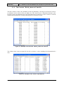
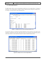
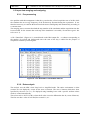
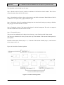
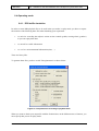
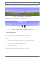
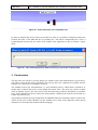
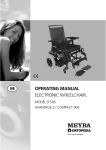
2-BE-SAFE
2-WHEELER BEHAVIOUR AND SAFETY
Grant Agreement number: 218703
Funding Scheme: Collaborative project small scale
Start date of the contract: 01/01/2009
Project website address: www.2besafe.eu
Software for the automatization of the
analysis of eye tracker's data while used
with the driving simulator
Confidentiality level: restricted
Deliverable D14 (WP, Activity 4.4)
Status: Final version
Date: 14/06/2010
Author: INRETS
Project Coordinator:
Scientific Coordinator:
Stéphane LAPORTE
Stéphane ESPIÉ
Europe Recherche Transport
INRETS c/o LCPC
2, rue de la Butte Verte
58 Bd Lefèbvre
F-93166 Noisy le Grand Cedex
F-75732 Paris Cedex 15
[email protected]
[email protected]
Phone: +33 (0)1 45 92 55 23
Phone: +33 (0)1 40 43 65 54
Authors
Name
Company
F. Vienne, S. Espié
INRETS
Amendments
Date of Issue
Description
07/05/2010
First draft by INRETS
14/06/2010
Modifications following the peer review
Applicable Documents
Description
<comments>
Acknowledgements
Description
<comments>
<Document ID : file name>
2/23
Table
1.
Identify static and dynamics areas of interest ..................................................................... 3
1.1.1.
Areas of interest: vehicles .............................................................................................. 5
1.1.2.
Areas of interest: objects ............................................................................................... 6
1.1.3.
Areas of interest: 3D polygons ....................................................................................... 7
1.2.
Displaying the areas of interest........................................................................................... 8
Input files of the application ............................................................................................................ 9
2.1.
Eye tracker’s output data files ........................................................................................... 10
2.1.1.
The FaceLab “Eye_<date>.txt” data file ...................................................................... 10
2.1.2.
The FaceLab “Timing_<date>.txt” data file ................................................................. 10
2.1.3.
The FaceLab “World_<date>.txt” data file .................................................................. 11
2.2.
DR2 output data file .......................................................................................................... 12
2.3.
Input data merging and analysing ..................................................................................... 13
2.3.1.
Pre-processing ............................................................................................................. 13
2.3.2.
Data analysis ............................................................................................................... 13
2.3.3.
Output file of the analysis software .............................................................................. 15
2.4.
Operating mode ................................................................................................................ 16
2.4.1.
DR2 traffic simulation ................................................................................................... 16
2.4.2.
SIM² driving simulator visual loop ................................................................................ 17
2.5.
3.
contents
Software for the automatization of the analysis of eye tracker's data ............................................ 3
1.1.
2.
of
Visual information.............................................................................................................. 18
Conclusions .................................................................................................................................. 19
LIST OF FIGURE .................................................................................................................................. 20
LIST OF TABLES .................................................................................................................................. 20
Document ID :
1
2-BE-SAFE
D14 : Software for the automatization of the analysis of eye tracker’s data
Executive summary
This report documents activities 4.4 “Car simulator”, sub activities 3, which objective is the design of
a software for the automatization of the analysis of eye tracker's data while used with the driving
simulator. This tool will be used in WP5.2 for conducting experiments on car simulator about rider’s
conspicuity.
The method used for the automatization is a post treatment process, which allows researchers to
analyse their recorded data and to easily change the interest areas. The areas may consist in either
static or dynamic objects. The areas can be easily described using symbolic description or geometric
faces. If the calibration of the eye tracker has been properly conducted, the software can be used in a
reliable and efficient way.
The produced software has been designed for the INRETS SIM² class simulators and for French users
(which are the users within 2BeSafe), but the method can be fairly easily adapted to other driving
simulators as well as the man machine interface language.
As a final result, the software has been designed, implemented and delivered, it fit the user
requirements.
Document ID :
2
2-BE-SAFE
D14 : Software for the automatization of the analysis of eye tracker’s data
1. Software for the automatization of the analysis of eye tracker's
data
The aim of this activity was the design of tools which helps the « final user » in setting and operating
the results of their experiments using eye tracker’s on simulators. Three integrated tools have been
designed:
1. An off-line one, allowing to precise elements in the visual scene which have to be considered
for the visual activity,
2. An on-line one, aiming at synchronizing the data acquired by the simulator and them acquired
by the eye tracker’s,
3. An off-line one, which allows calculating the duration of the fixation point (object in space at
which sight is aimed) for each considered elements.
It has to be considered that such tools are, to a large extent, simulator and eye tracker’s dependant, as
the 3D database format, the 3D rendering engine and the eye tracker’s manufacturer are often different
from simulator to simulator. Thus, the tools designed in this activity are dedicated to the simulator
used in WP5.2, which is a INRETS SIM² class simulator, and to the FaceLab eye tracker’s. The
INRETS-SIM² simulator architecture is an open and modular architecture which is used in several
research labs in France, and also in some foreign research labs.
Compare to existing systems, for example the Oktal one, the tools have been designed in such a way
that they simplify the configuration and the analysis by non expert users. The first step, consisting in
defining the elements considered for the visual activity, do not require skills in info graphics as the
user can precise areas in the 3D database without using a 3D modeller.
The process, which assumes that the protocol of the experiment has been properly defined, consists in:
1. Achieving the experiment using the simulator and the FaceLab eye tracker’s, in this step data
from eye tracker’s and data from the driving simulator are recorded,
2. Determining the elements or areas of interest for the visual activity. Three kinds of elements
can be defined: vehicles, road signs and areas. Vehicles and road signs are identified
symbolically, while areas are defined using the coordinates of 3D rectangle faces. The defined
areas can be double checked visually, using the driving simulator visual loop,
3. Analysing the data, using a replay mode which allows correlating the data acquired by the eye
tracker’s, the data acquired by the driving simulator and the data defined for the study of the
visual activity.
It has to be stressed that the step 1 can be achieved before the step 2, but has of course to be achieved
before the step 3.
It has also to be noticed that the design of the tools in such a way allows the processing of the data
acquired in previous experiments.
The following sections explain the process and may be used as a user manual. As the software is
primarily intended to be used by French users, the language used is the French.
1.1. Identify static and dynamics areas of interest
The software allows selecting up to 20 areas of interest for the experiment. This characteristic has
been defined jointly with the researchers of WP5.2, it can be easily increased up to 255.
Three categories of areas of interest can be specified:
•
vhs (vehicles)
•
panneau (sign or object)
•
face (polygon)
Document ID :
3
2-BE-SAFE
D14 : Software for the automatization of the analysis of eye tracker’s data
These data have to be specified in an ASCII file named "ZoneInteret.txt”. Figure 1 is an example of
such a file:
Figure 1 - Symbolic description of areas of interest (vehicles and signs)
The "vhs" (vehicles) category creates a dynamic area moving with the vehicle of which you specify
the identification number within the simulation. The identification number consists in the DR2 ID of
the vehicle, DR2 being the software in charge of the traffic simulation within the INRETS SIM²
simulator architecture.
Syntax: vhs + DR2 ID of the vehicle
“vhs 0” means that we determine the time of fixation on vehicle # 0 when it is displayed.
The "panneau" (sign or object) category allows to create an area of interest related to an object from
the static background (road sign, tree, house ...) you specify the identification number within the
simulation. The identification number consists in the SIM² type of the object, as the objects of this
category are not always managed by the traffic simulation. In order to avoid confusion, the location of
the object is added, using the curvilinear position of the object along a specific road.
Syntax: panneau + SIM² ID of the object + road number + lateral position of the object (dm) +
kilometric position of the object (dm).
“panneau 0 1 80 30000” means that the area of interest will be linked to the object # 0 located on road
number 1 at kilometric point (KP) 3.0000 and located at a lateral position of 8 meters.
The "face" category allows creating a zone of fixed interest whose location is specified by the 4
vertices of the face.
Syntax: face + name + list of the co-ordinates of the 4 vertices
“face building 1 (674.932050,34.8886820,13.5751250)(
674.024390,34.8777690,3.2048E-01)(651.215930,34.6028970,2.5106E-01)
(654.450030,34.6420930,13.4708410)” means that the area of interest
consists in a polygon defined by the co-ordinates which are précised.
Document ID :
4
2-BE-SAFE
D14 : Software for the automatization of the analysis of eye tracker’s data
There is no obligation to design a rectangle. The interior angles do not need to be straight.
An additional module has been added to the SIM² application, which provides an interface to select
and specify the various parameters involved. To access them, you must:
1. Load and display your 3D base by choosing the right track in SIM²
2. Not be connected with DR2 (which mean off-line use of SIM²)
3. Select helicopter view by pressing F9.
Figure 2 is the dialog box which allows to precise the areas of interest.
Figure 2 - Areas of interest selection dialog box
This dialog box is used for multiple purposes, only the « zone d’interet » part (bottom, right) is used
for identifying the areas of interest.
1.1.1. Areas of interest: vehicles
If "Vhs" (vehicles) is checked, then appears on the screen a new dialog box (Figure 3):
Document ID :
5
2-BE-SAFE
D14 : Software for the automatization of the analysis of eye tracker’s data
Figure 3 - Vehicle ID number specification
One must specify the DR2 identification number of the vehicle concerned.
1.1.2. Areas of interest: objects
If "panneau" (objects) is checked, the following dialogs will appear (Figure 4):
Figure 4 - "panneau" ID type specification
One must specify the position of the SIM² ID type for the object.
Then, one has to specify a position. First, one specifies the road's identification number (DR2
reference, Figure 5):
Figure 5 -Road ID number specification
Document ID :
6
2-BE-SAFE
D14 : Software for the automatization of the analysis of eye tracker’s data
As well as its lateral position (in dm, Figure 6):
Figure 6 - Lateral position specification
And at last it’s KP (in dm, Figure 7):
Figure 7 - KP specification
1.1.3. Areas of interest: 3D polygons
In the case of a "face", one has to press the space bar when the mouse cursor is in the right positions.
The application determines the first polygons encountered in the virtual world automatically. When
the fourth and last vertex is specified, the following dialog appears on the screen (Figure 8):
Figure 8 - Face name specification
This allows the user to remember more easily what this "face" represents. One will then be ask to
confirm the choice of name (here, "tt", Figure 9):
Document ID :
7
2-BE-SAFE
D14 : Software for the automatization of the analysis of eye tracker’s data
Figure 9 - Confirmation for a "face" area of interest
If one click on "Oui", the "face" specification is stored in the file, otherwise not.
1.2. Displaying the areas of interest
Here is an example of an initial view of the driving area, with two objects:
•
A dynamic, car number 0.
•
A static, a speed limit sign (position: route 17 / lane position: -40 dm / KP: 14900 dm).
Figure 10 - Initial view taken during the experiment
We thus want to create two zones of interest, one for each object. This means creating a file containing
all the required information. Figure 11 shows such an ASCII file.
Figure 11 - Example of "ZoneInteret" parameter file
Document ID :
8
2-BE-SAFE
D14 : Software for the automatization of the analysis of eye tracker’s data
When one executes the application in eye tracker’s replay mode, one gets the following display
(Figure 12):
Figure 12 - Eye tracker’s replay mode
Note that both objects are now encompassed by rectangular parallelepipeds that hug the shapes of
objects. The notion of distance between the "faces" nearest to the object is very important. In fact, the
calculation of fixation durations in each zone is based on the intersection of the measured gaze with
the parallelepiped. An error may be induced if the object is too broadly embraced. A considerable
amount of work has been done to minimise these errors.
Note: the entire visual base is completely white (no textures), except for the areas of interest.
2. Input files of the application
The application which analyse visual activity requires three input files. The first comes from the
merging of the eye tracking files (1), the second from the data generated by DR2 (2) and the third is
the previously defined parameters file describing the areas of interest (Figure 13).
.var file
Input file
Input file
(2)
Parameters file
Eye tracker’s
Files:
Eye, Timing
& World
DR2 / SIM²
Analysis
of
tracker’s results
(1)
eye
Output file
Figure 13 - Schematic representation of the application's inputs and outputs
Document ID :
9
2-BE-SAFE
D14 : Software for the automatization of the analysis of eye tracker’s data
2.1. Eye tracker’s output data files
The FaceLab eye tracker generates four files. The first one, “<date>.entree“, contains the information
of interest from the three other .txt files. The name of each of the files generated by the eye tracker
precise the date of the experiment. The <date> string being composed of: Weekday + month + day +
year + hour + minute + second corresponding to the start of the eye tracking acquisition (e.g.
Timing_Tue_Sep_8_2009_14_26_36.txt).
The following sections details each data file generated by the eye tracker.
2.1.1. The FaceLab “Eye_<date>.txt” data file
This file contains 2 values: GAZE_QUAL_R and GAZE_QUAL_L. (see Figure 14)
These correspond to the pupil detection quality. A value of 2 is required to use the position values.
This is a filter in the treatment of eye tracking data.
Figure 14 - Example of FaceLab “Eye_<date>.txt” data file
2.1.2. The FaceLab “Timing_<date>.txt” data file
This file contains 2 values: GMT_S and GMT_MS
GMT_S is the GMT date in seconds of each acquisition. GMT_MS corresponds to the part in
milliseconds to add to the previous value. A utility allows to rewrite the data in HH:MM:SS.sss
notation to compare with the time from the DR2 recordings.
Document ID :
10
2-BE-SAFE
D14 : Software for the automatization of the analysis of eye tracker’s data
2.1.3. The FaceLab “World_<date>.txt” data file
This file contains 2 values: GSI_WORLD_X and GSI_WORLD_Y which give the FaceLab X and Y
co-ordinates on the virtual screen (see Figure 15). The virtual screen is determined directly by the
FaceLab system. Its dimensions have been integrated into our software in order to achieve a relevant
normalisation and therefore a good positioning on one of our three screens.
Figure 15 - Example of the FaceLab “World_<date>.txt” data file
The software thus creates an input file for the eye tracker’s values including the aforementioned 6
data.
Figure 16 - Example of the "entree" input data file
Document ID :
11
2-BE-SAFE
D14 : Software for the automatization of the analysis of eye tracker’s data
2.2. DR2 output data file
The DR2 software allows to precise the parameters which have to be recorded (Figure 17) during an
experiment. The recording period is indicative and may slightly fluctuate during the recording due to,
for example, a slowdown in the visual rendering process.
Figure 17 - Sample of the .enr Dr2 recording parameters file
The output file (Figure 18) contains the requested information. In the example: the step number of the
simulation, acquisition time and many other data specific to the experiment, among them the position
of the subject vehicle’s on the road network and of 25 traffic vehicles he interacts with.
Figure 18 - Sample of the .var Dr2 output data file
Document ID :
12
2-BE-SAFE
D14 : Software for the automatization of the analysis of eye tracker’s data
2.3. Input data merging and analysing
2.3.1. Pre-processing
One problem with this arrangement is that the eye tracker has a fixed acquisition rate of 60 Hz while
the simulator has an average frequency of 60 Hz that may fluctuate during the experiment. It was
therefore necessary to combine the data from both sources intelligently and automatically according to
a common time.
The merging process assumes that both the step number of the simulation and the acquisition time has
been recorded. It also assumes that each step of the simulation is recorded (“PeriodeSauvegarde” has
to be set at -1).
A file “EntreeDr2” (Figure 19) is created based on the DR2 output file. A column corresponding to
the number of seconds and milliseconds since the start of the day is added for the purpose of
comparison with the eye tracking data.
Figure 19 - The "EntreeDr2" intermediate data file
2.3.2. Data analysis
The analysis uses the SIM² visual loop but in a simplified mode. The entire environment is white
(textures are not displayed), except for the areas of interest. The area of interest which have been
specified by the user (see 1.1), are displayed using bounding boxes with a specific uniform colour
which is created automatically
The colour code is: R XX G 0 B 0, where the R value is used to differentiate the AI (Areas of Interest).
The first area has a value of 0.05 Red, the second 0.1, etc ...
Document ID :
13
2-BE-SAFE
D14 : Software for the automatization of the analysis of eye tracker’s data
The algorithm can be divided into five steps:
Step 1: Retrieval of the X and Y position co-ordinates of the FaceLab virtual window. This is done
using information from the file "date.entree".
Step 2: Normalisation of these values to place them in the SIM² environment. Identification of which
of the three views (left, centre, right) contains the gaze.
Step 3: Projection of this 2D coordinates display into the virtual world, using ray tracing to find the
first polygon encountered in the 3D world.
Step 4: Testing the colour of the intersected polygon for its Red component. The value is compared
with that of different areas until a match is found.
Step 5: Two possible cases:
The gaze was not within this AI at the previous time step. A new fixation period is thus created.
The gaze was within this AI at the previous time step. The duration of the current fixation period is
thus updated.
Duration of the current fixation (step t + 1) = Duration of the current fixation (step t) + time between
the two steps (t and t +1).
Figure 20 describe the fixation algorithm.
Figure 20 - Fixation time algorithm
Document ID :
14
2-BE-SAFE
D14 : Software for the automatization of the analysis of eye tracker’s data
2.3.3. Output file of the analysis software
At the end of the eye tracker data analysis process, the application has generated an output file
containing all the areas of interest set during the experiment.
This file (Figure 21) specifies:
•
tempsOrigineOculoGMT: to refer to the eye tracker input files. This gives the possibility to
carry out offline cross comparisons.
•
tempsOrigine: time since the beginning of the experiment. Value obtained from the simulator
data.
•
noZone: the number of the zone of interest. Remember, this number depends on the line
number in the file "ZoneInteret.txt (the first line being number 0).
•
pas: the step number in DR2's iterative loop. Also provides a reference to synchronise with
respect to the .var file. Of interest mainly in relation to scenario data. With this, we may
associate the simulation time and the experimentation timing (the position in scenario).
•
dureeFixation: time during which the eye fixed the same IA without leaving this area.
Figure 21 - Sample output of the eye tracker's data analysing tool
Document ID :
15
2-BE-SAFE
D14 : Software for the automatization of the analysis of eye tracker’s data
2.4. Operating mode
2.4.1. DR2 traffic simulation
In order to create DR2 playback files to be used in the eye tracker’s replay mode, you have to request
the creation of the following three files when launching your experiment:
•
res-mdv.bin: recording the subject's actions on the controls (pedals, steering wheel, gearbox)
so you can replay them later.
•
res-monde.bin: traffic information
•
res-env.bin: environnemental information (time, ...)
These are binary files.
To generate these files, you have to tick "Enregistrement" as shown below:
Figure 22 - Requestion the recording of playback data
When you want to obtain your output file with the fixation times on the different areas of interest, you
must specify that you are in replay mode:
Document ID :
16
2-BE-SAFE
D14 : Software for the automatization of the analysis of eye tracker’s data
Figure 23 – Eye tracker’s replay mode selection
2.4.2. SIM² driving simulator visual loop
To display the eye tracking mode in Sim2 (all white with the ZI in shades of red) you have to
modify the value of the "enregistrementOculo" option in the info.simu file as shown in figure
23.
Figure 24 - Sample of the info.simu file set for eye tracker’s replay mode
Document ID :
17
2-BE-SAFE
D14 : Software for the automatization of the analysis of eye tracker’s data
If this option is set to 0, you will obtain a standard, non-replay eye tracking display as shown below:
Figure 25 - Standard display during experimentation
If the option is set to 2, one obtains the eye tracker’s replay mode:
Figure 26 - Simplified view in the eye tracker’s replay mode
2.5. Visual information
The software provides several visual indicators directly on the Sim² interface.
These are:
•
HeureGMT .var: the GMT time obtained from the .var file generated by DR2.
•
HeureGMT .oculo: the GMT time from the eyetracker.
•
A cursor indicating the gaze.
Note: the difference between the GMT times should never exceed 16ms.
Document ID :
18
2-BE-SAFE
D14 : Software for the automatization of the analysis of eye tracker’s data
Figure 27 - Visual indicators in the simplified view
In order to configure the device in the best possible way, there is a possibility of adding an offset time
between the timer of the DR2 and the eye tracking PCs. This allows compensating for a lack of
synchronisation between the two clocks at the launch of the application in the eye tracker’s replay
mode.
Figure 28 - Time offset specification when launching in eye tracker’s replay mode
3. Conclusions
The aim of the 4.4 activities 3 was the design of a software tool for the automatization of eye tracker’s
data while used with the driving simulator. This activity has been conducted successfully and the
software was “delivered” to researchers of WP5.2.
The method used for the automatization is a post treatment process, which allows researchers to
analyse their recorded data and to easily change the interest areas. The areas may consist in either
static or dynamic objects. The areas can be easily described using symbolic description or geometric
faces. If the calibration of the eye tracker has been properly conducted, the software can be used in a
reliable and efficient way.
The produced software has been designed for the INRETS SIM² class simulators and for French users
(which are the users within 2BeSafe), but the method can be fairly easily adapted to other driving
simulators as well as the man machine interface language.
Document ID :
19
2-BE-SAFE
D14 : Software for the automatization of the analysis of eye tracker’s data
LIST OF FIGURE
Figure 1 - Symbolic description of areas of interest (vehicles and signs) ............................................... 4
Figure 2 - Areas of interest selection dialog box ..................................................................................... 5
Figure 3 - Vehicle ID number specification.............................................................................................. 6
Figure 4 - "panneau" ID type specification .............................................................................................. 6
Figure 5 -Road ID number specification .................................................................................................. 6
Figure 6 - Lateral position specification ................................................................................................... 7
Figure 7 - KP specification....................................................................................................................... 7
Figure 8 - Face name specification ......................................................................................................... 7
Figure 9 - Confirmation for a "face" area of interest ................................................................................ 8
Figure 10 - Initial view taken during the experiment ................................................................................ 8
Figure 11 - Example of "ZoneInteret" parameter file ............................................................................... 8
Figure 12 - Eye tracker’s replay mode .................................................................................................... 9
Figure 13 - Schematic representation of the application's inputs and outputs ........................................ 9
Figure 14 - Example of FaceLab “Eye_<date>.txt” data file.................................................................. 10
Figure 15 - Example of the FaceLab “World_<date>.txt” data file ....................................................... 11
Figure 16 - Example of the "entree" input data file ................................................................................ 11
Figure 17 - Sample of the .enr Dr2 recording parameters file ............................................................... 12
Figure 18 - Sample of the .var Dr2 output data file ............................................................................... 12
Figure 19 - The "EntreeDr2" intermediate data file ............................................................................... 13
Figure 20 - Fixation time algorithm ........................................................................................................ 14
Figure 21 - Sample output of the eye tracker's data analysing tool ...................................................... 15
Figure 22 - Requestion the recording of playback data ........................................................................ 16
Figure 23 – Eye tracker’s replay mode selection .................................................................................. 17
Figure 24 - Sample of the info.simu file set for eye tracker’s replay mode ........................................... 17
Figure 25 - Standard display during experimentation ........................................................................... 18
Figure 26 - Simplified view in the eye tracker’s replay mode ................................................................ 18
Figure 27 - Visual indicators in the simplified view ................................................................................ 19
Figure 28 - Time offset specification when launching in eye tracker’s replay mode ............................. 19
LIST OF TABLES
Tableau 1 - Parameters for the central rear view rendering .................................................................. 14
Document ID :
20
Document ID :
21